

Page 1
Installation Instructions
Gas-Hob
KM 404
IMPORTANT NOTICE
THIS APPLIANCE MUST ONLY BE INSTALLED OR SERVICED
BY AUTHORISED PERSONNEL
Note: The installation of this appliance must comply with the requirements of the National
Standard or AS 5601 (AG 601) Gas Installations.
It is essential to read these
operating instructions before
installing or using the machine,
to avoid the risk of accident
or damage to the machine. M.-Nr.05 667 660
r
Page 2

Contents
Contents
Warning and Safety Instructions . . . . . . . . . . . . . . . . . . . . . . . . . . . . . . . . . . . . . 3
Building in . . . . . . . . . . . . . . . . . . . . . . . . . . . . . . . . . . . . . . . . . . . . . . . . . . . . . . . . 3
Safety distance above appliances . . . . . . . . . . . . . . . . . . . . . . . . . . . . . . . . . . . 4
Appliance dimensions. . . . . . . . . . . . . . . . . . . . . . . . . . . . . . . . . . . . . . . . . . . . . . 5
Worktop cut-out . . . . . . . . . . . . . . . . . . . . . . . . . . . . . . . . . . . . . . . . . . . . . . . . . . . 6
Installation . . . . . . . . . . . . . . . . . . . . . . . . . . . . . . . . . . . . . . . . . . . . . . . . . . . . . . . 7
Fitting the spacer bars and support brackets . . . . . . . . . . . . . . . . . . . . . . . . . . . . . 7
Fixing the spacer bar . . . . . . . . . . . . . . . . . . . . . . . . . . . . . . . . . . . . . . . . . . . . . . . 8
Granite worktops. . . . . . . . . . . . . . . . . . . . . . . . . . . . . . . . . . . . . . . . . . . . . . . . . 8
Fixing the support brackets . . . . . . . . . . . . . . . . . . . . . . . . . . . . . . . . . . . . . . . . . . . 9
Building in the gas hob . . . . . . . . . . . . . . . . . . . . . . . . . . . . . . . . . . . . . . . . . . . . . . 9
Electrical connection . . . . . . . . . . . . . . . . . . . . . . . . . . . . . . . . . . . . . . . . . . . . . . 11
Technical Data . . . . . . . . . . . . . . . . . . . . . . . . . . . . . . . . . . . . . . . . . . . . . . . . . . . . 12
Gas connection . . . . . . . . . . . . . . . . . . . . . . . . . . . . . . . . . . . . . . . . . . . . . . . . . . 13
Conversion to another type of gas. . . . . . . . . . . . . . . . . . . . . . . . . . . . . . . . . . . 15
Jet table . . . . . . . . . . . . . . . . . . . . . . . . . . . . . . . . . . . . . . . . . . . . . . . . . . . . . . . . . 15
Changing the jets. . . . . . . . . . . . . . . . . . . . . . . . . . . . . . . . . . . . . . . . . . . . . . . . . . 16
2
Page 3
Warning and Safety Instructions
Warning and Safety Instructions
Building in
To avoid damage to the hob install
it after fitting any wall cabinets
The veneer or laminate coatings of
worktops (or adjacent kitchen units)
must be treated with 100°C heat-resistant adhesive which will not dissolve or
distort.
Any backmoulds must be of heat-resistant material.
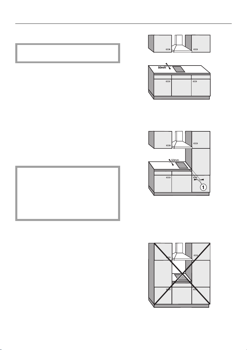
Ideally the hobs should be installed
with plenty of space on either side.
There may be a wall at the rear and
wall or tall units at one side. On the
other side however, no unit or divider
should stand higher than the hob.
A safety distance must be maintained between the hob and adjacent furniture, because of the heat
given off by the flames, and to allow
fumes to dissipate; with a tall unit
for example at least
100 mm with KM 404.
The gas hob must not be installed next
to an electric deep fat fryer, as the gas
flames could ignite the fat in the fryer.
It is essential to maintain a distance of
at least 288 mm between these two appliances.
Fig.1
recommended
Fig. 2
possible but not recommended
Measurement
(minimum distance)
at least 100 mm
b
The hob must not be installed over a
dishwasher, washing machine, tumble
dryer, refrigerator or freezer. The high
temperatures radiated by the hob
could damage the appliance below.
Fig 3
not allowed
3
Page 4
Warning and Safety Instructions
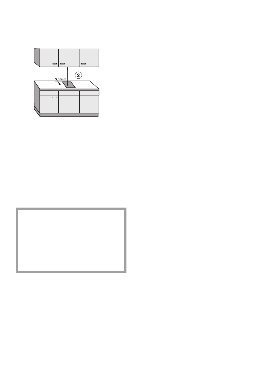
Safety distance above the appliance
Fig. 4
As a general rule there must be a
c
safety distance of at least 760 mm
between the appliance and any
flammable objects sited above, e.g.
wall units. If the manufacturer of the
said objects states a different figure,
either greater or smaller, then this
should be adhered to.
When two or more appliances are installed together, the maximum distance quoted between the cooker
hood and the appliance must always be observed. These measurements are given in the operating
and installation instructions for the
cooker hood.
Space required for gas appliances
Minimum requirements are more than
3
20 m
space where the appliance is installed, and a door or window which
can be opened to the outside air.
All dimesions in this instruction booklet
are given in mm.
Keep these instructions in a safe place
and pass them on to any future owner
of the appliance.
4
Page 5
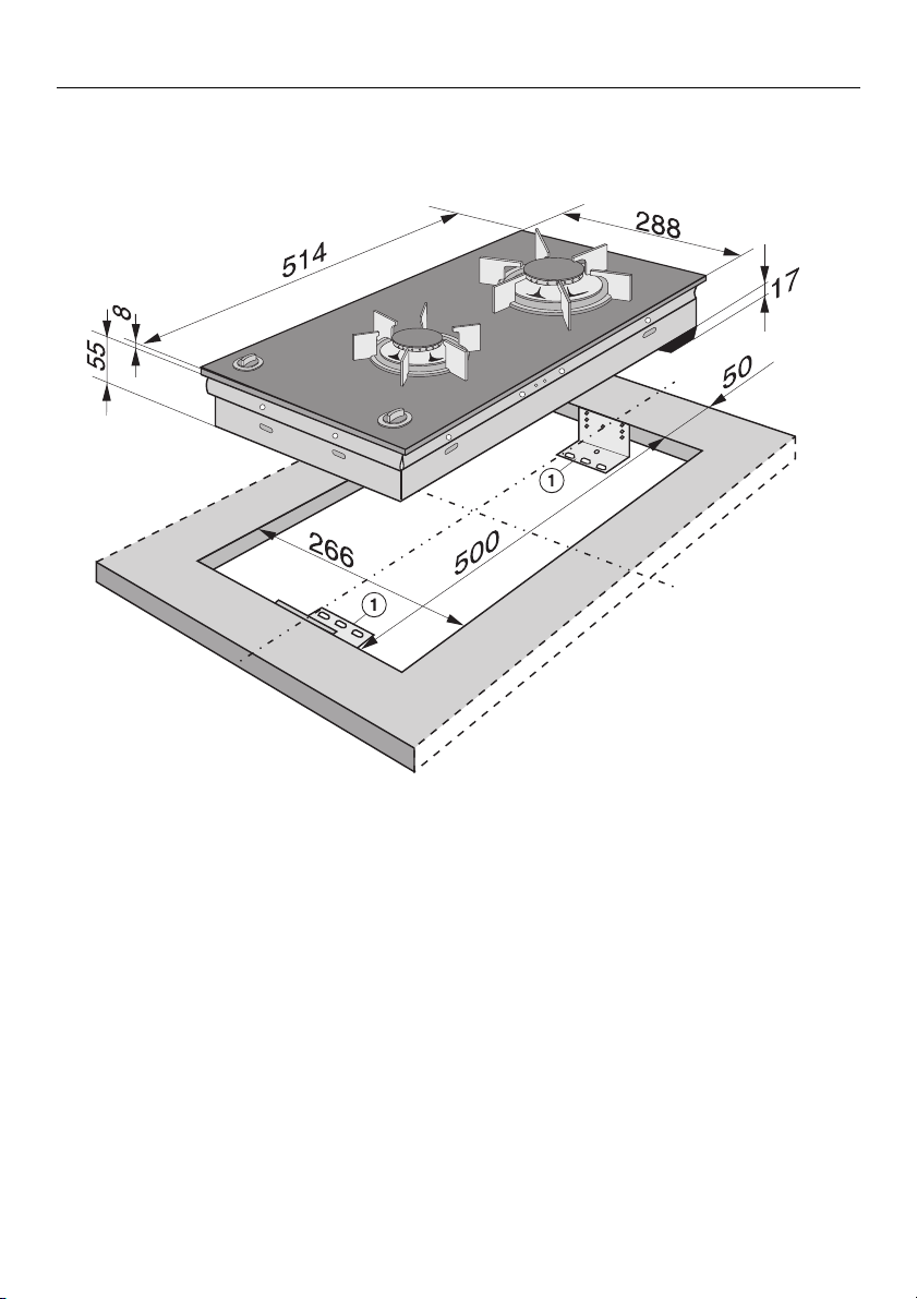
Appliance dimensions
KM 404
Appliance dimensions
Support bracket
b
Fig. 5
5
Page 6

Installation
Installation
Cut-out for the worktop
Fig. 6
Make a cut-out for the hob in the
worktop, paying attention to the appliance depth. See Figures 5, 6,
and 7.
Dimension ‘B’ applies to a combination of appliances and is shown on
the chart.
There must be a minimum distance
of 50 mm between the hob and the
back wall and 100 mm distance from
a side wall to the right or left of the
hob.
See also ‘‘Warning and Safety Instructions’’.
Depth
in mm
+
1 mm
Width
(=Dim. B)
in mm
+
1 mm
Worktop cut-out
1 hob
2 hobs
3 hobs
4 hobs
5 hobs
6 hobs
7 hobs
500
500
500
500
500
500
500
266
554
842
1130
1418
1706
1994
Important:
The maximum tolerance for the worktop
+
cut-out must not exceed
1 mm.
When building in several “combi”
hobs a spacer bar must be fitted between each unit.
See the following page.
Seal the cut surfaces with a suitable
sealant to avoid swelling caused by
moisture.
The materials used must be heat resistant.
6
Page 7

Fitting the spacer bars and
support brackets
Installation
Fig. 7
Support brackets
b
Spacer bars
c
Figure 7 shows an example for worktop
cut-out and fixing the spacer bars
and support brackets b for 3 appliances.
For more than 3 appliances, repeat
dimension 288 mm.
The worktop cut-out dimensions for several appliances are shown in the table
on the previous page.
c
Gap between spacer bar and
d
worktop.
Drilling for a granite worktop.
e
Fix the spacer bars c and the support brackets
sitions indicated. See also figures 8
and 9.
supplied to the po-
b
7
Page 8

Installation
Fixing the spacer bar
d
c
Fig. 8
Lay the spacer bars c on the top
edge of the cut-out in the positions
indicated (Fig. 7), as shown in Fig. 8,
and secure with the 3.5 x 25 mm
screws supplied.
Then fill in the gap d between the
bars and the worktop with silicone
from the tube supplied.
For granite worktops
With granite worktops the spacer bars
must be positioned and secured
c
with strong double-sided adhesive
tape. In addition, coat the edges with
silicone and fill in the gap
The screws are not necessary for granite tops.
d
.
8
Page 9

Installation
Fixing the support brackets
Fig. 9
Position the support brackets supplied
as shown in Fig. 9, flush with the top
edge of the worktop, and secure
with the 3.5 x 25 mm screws supplied.
2 screws are needed to secure the
support brackets.
The thickness of the worktop will
determine which drilled hole is used.
(2 pieces) (see also Fig. 7),
b
For granite worktops
A granite worktop must be prepared with a hole drilled
positions indicated to secure each
support bracket, (see Figs. 7 and 9).
Using a piece of double-sided
strong adhesive tape press the support brackets supplied
position indicated (Fig. 7), as shown
in Fig 9 , flush with the top edge of
the worktop and secure each
bracket with one screw.
at the
e
on to the
b
9
Page 10

Installation
Building in the gas hob
Lay the gas hob in the prepared cutout.
Draw the electricity connection cable
through the cut-out and connect.
Make the gas connection.
(see the following pages).
Secure the gas hob from below
through the middle elongated hole
(see Fig. 9) using the two screws
c
supplied. Gently adjust the hob if
necessary.
Fig. 10
On no account let sealant get in
between the hob frame and the
worktop.
This could lead to damage to the hob if
it needs to be taken out for servicing or
repair work. The seal provided underneath the hob edge provides a sufficient seal between the appliance and
the worktop.
10
Page 11

Other notes
Other notes
Electrical connection
Electrical work should be carried out by
a competent person, in strict accordance with national and local safety
regulations.
The voltage and rated load are given
on the data plate. Ensure that these
match the household mains supply.
After the appliance has been built in,
a check must be made that all electrical parts are shielded.
Connection for each appliance should
be made via a suitable isolator (rated
load above 3 kW) or a double pole
fused spur connection unit or fused
plug and switched socket (rated load
up to 3 kW) which complies with national and local safety regulations, and
which is accessible after the appliance
has been built in.
When switched off there must be an allpole gap of at least 3 mm in the isolator
switch. For extra safety it is advisable
to install a residual current device
(RCD) with a trip current of 30 mA.
Important
The wires in the mains lead are coloured in accordance with the following
code:
Green/yellow = earth
Blue = neutral
Brown = live
Disconnection from the power supply
will depend on the isolator, according
to country e.g.:
1. Safety fuse:
Completely remove the fuse links
from the fuse carrier. or:
2. Safety cut-outs (screw type):
Press the (red) test button until
the black centre button pops out.
or:
3. Built-in safety cut-outs (MCBs at
least type B or C):
Set rocker from 1 (On) to O (OFF) or:
4. FI-Safety switch (RCD)
Set main switch from 1 (ON) to
O (Off) or press the test button.
Technical Data
Fusing: See data plate.
For appliances up to 3 kW - 13 amps
For appliances above 3 kW - 20 amps
If the cable needs to be changed select either type H 05 RR-F (rubber insulated) or type H 05 VV-F (PVC-insulated).
See data plate for connection data.
Important
The manufacturer cannot be held responsible for the consequences of an
inadequate earthing system.
WARNING THIS APPLIANCE MUST
BE EARTHED
Ensure power is not restored to the
appliance while installation work is
being carried out.
The manufacturer can assume no responsibility for damage which is the direct or indirect result of incorrect installation or connection.
11
Page 12

Gas connection
Gas connection
Connection to the gas supply
should only be undertaken by an approved fitter, who is responsible for
correct functioning of the appliance
when installed. Every appliance
should have its own isolating valve.
Check with your local gas supplier
about the type of gas and its calorific value, and compare this information with the type of gas quoted
on the hob data plate.
The hob is supplied ready for connection to town gas.
Connection
Conversion to another type of gas is described under the relevant section.
The gas connection must be installed so that connection can be
made either from inside or outside
the kitchen unit, and the isolating
valve must be easily accessible and
visible (by opening one of the kitchen unit doors, if necessary).
12
Page 13

Technik
The gas connection must be in accordance with national and local
regulations.
Fig. 11
Gas connection
Town gas / LP gas
An appropriate rigid or flexible connection can be used.
The gas connection must be so sited
that it is not adversely heated when
the appliance is in operation.
When the gas hob has been installed it is essential to check that
neither the gas hose nor the electricity cable is in contact with hot
parts of the appliance or hot gas exhaust, otherwise heat damage to
the hose and cable could occur.
Connection for pressure gauge
b
Governor fitted for connection to
c
town gas. Inlet pressure 10-20 mbar/
1-2 kPa, burner pressure 10 mbar/
1 kPa.
A test for possible leakages should
be carried out after installation.
The relevant building regulations must
also be observed.
Note: Where a flexible connection (Hose Assembly) is used it must
(I) be of an adequate size and;
(II) comply with the National standard or AGA certification and;
(III) be suitable for the intended use.
13
Page 14

Conversion to another type of gas
Conversion to another type of gas
KM 404
When converting to LP gas, the
main jets and the small jets of all
burners must be changed.
Nominal rating at high setting
Normalburner
Fastburner
Gas type
Supply pressure
Towngas
10-20 mbar /
1-2 kPa
LP gas
30 mbar /
3 kPa
Towngas
10-20 mbar /
1-2 kPa
LP gas
30 mbar /
3 kPa
kW MJ/h
1.9
1.6
3.1
2.7
7.0
5.6
11.2
9.7
Screw in the new jets according to the
following table.
Jet table
Main-jet
Ø
Town gas
Normal burner
Fast burner
1.85
2.75
LP gas
30 mbar
Normal burner
Fast burner
0.65
0.85
The jet markings refer to 1/100 mm of
the jet orifice.
Total rating
Low
setting jet
Ø
0.74
0.88
0.27
0.36
Nominal rating at low setting
Normalburner
Fastburner
14
Gas type
Supply pressure
Towngas
10-20 mbar /
1-2 kPa
LP gas
30 mbar / 3 kPa
Towngas
10-20 mbar /
1-2 kPa
LP gas
30 mbar / 3 kPa
kW MJ/h
0.3
0.3
0.5
0.4
1.2
1.0
1.7
1.5
Towngas
LP gas
kW MJ/h
5.06
4.25
18.2
15.3
Page 15

Conversion to another type of gas
Changing the jets
Disconnect the gas hob from the
electricity supply. Depending on the
type of installation, either withdraw
the mains fuse, switch of at the
fused spur unit, or at the socket and
withdraw the plug.
Changing the main jets
Changing the low setting jet
Fig. 13
Guide a screwdriver throug the holes
in the lower casing of the hob and
loosen the low setting jets
Pull the jets out with a pair of pliers.
Put in the new jets and secure with a
screwdriver.
g
.
Fig. 12
Take off the pan support, the burner
cover
burner head
Using an (M7) socket spanbner inscrew the main jet
Change the main jet.
Reassemble the burner head, burner
ring and burner cover in the correct
order.
, the burner ring d and the
c
.
e
.
f
Fix the jets and air-setting with sealing-wax against accidental loosening.
At low setting the flame must not extinguish, even when the control
switch is turned fast from “High” to
“Low” setting.
At “High” setting the flame must burn
with a clearly visible core.
15
Page 16

Alteration rights reserved 00/3301
This paper consists of cellulose which has been bleached without the use of chlorine.
 Loading...