

Page 1
Installation Instructions
Ceramic hobs
KM 400 / KM 412 / KM 418
Ceramic contact grill KM 408-1
Open grill KM 410 / KM 411
Deep fat fryer KM 402
It is essential to read these
instructions before installing
or using the machine, to avoid
the risk of accident or
damage to the machine. M.-Nr. 05 021 212
WO
Page 2

Contents
Warning and Safety instructions . . . . . . . . . . . . . . . . . . . . . . . . . . . . . . . . . . . . . 3
Building in . . . . . . . . . . . . . . . . . . . . . . . . . . . . . . . . . . . . . . . . . . . . . . . . . . . . . . . . 3
Additional safety notes on induction hobs / KM 418 . . . . . . . . . . . . . . . . . . . . . 4
Safety distance above the appliance . . . . . . . . . . . . . . . . . . . . . . . . . . . . . . . . . 4
Safety distance between the KM 410 / KM 411 and a cooker hood above it . . 5
Appliance dimensions. . . . . . . . . . . . . . . . . . . . . . . . . . . . . . . . . . . . . . . . . . . . . . 6
KM 400 / KM 408-1 / KM 412. . . . . . . . . . . . . . . . . . . . . . . . . . . . . . . . . . . . . . . . . . 6
KM 402. . . . . . . . . . . . . . . . . . . . . . . . . . . . . . . . . . . . . . . . . . . . . . . . . . . . . . . . . . . 7
KM 410 / KM 411 . . . . . . . . . . . . . . . . . . . . . . . . . . . . . . . . . . . . . . . . . . . . . . . . . . . 8
KM 418. . . . . . . . . . . . . . . . . . . . . . . . . . . . . . . . . . . . . . . . . . . . . . . . . . . . . . . . . . . 9
Worktop cut-out . . . . . . . . . . . . . . . . . . . . . . . . . . . . . . . . . . . . . . . . . . . . . . . . . . 10
Installation . . . . . . . . . . . . . . . . . . . . . . . . . . . . . . . . . . . . . . . . . . . . . . . . . . . . . . 11
Fitting the spacer bars and spring clamps . . . . . . . . . . . . . . . . . . . . . . . . . . . . . . 11
Fixing the spacer bars . . . . . . . . . . . . . . . . . . . . . . . . . . . . . . . . . . . . . . . . . . . . . . 12
Granite worktops. . . . . . . . . . . . . . . . . . . . . . . . . . . . . . . . . . . . . . . . . . . . . . . . 12
Fixing the spring clamps . . . . . . . . . . . . . . . . . . . . . . . . . . . . . . . . . . . . . . . . . . . . 12
Granite worktops. . . . . . . . . . . . . . . . . . . . . . . . . . . . . . . . . . . . . . . . . . . . . . . . 12
Building in the appliance . . . . . . . . . . . . . . . . . . . . . . . . . . . . . . . . . . . . . . . . . . . . 13
General . . . . . . . . . . . . . . . . . . . . . . . . . . . . . . . . . . . . . . . . . . . . . . . . . . . . . . . . . 14
Electrical connection . . . . . . . . . . . . . . . . . . . . . . . . . . . . . . . . . . . . . . . . . . . . . 15
2
Page 3
Warning and Safety instructions
Building in
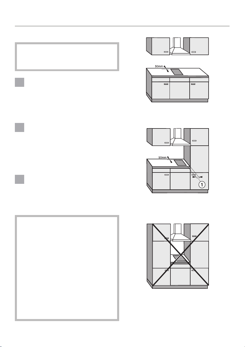
Fit wall units and the cooker hood
before fitting the appliance, to avoid
damaging it.
The veneer or laminate coatings of
worktops (or adjacent kitchen
units) must be treated with 100 °C heat
resistant adhesive which will not dis
solve or distort. The worktop upstand
must be heat-resistant.
Ideally the appliances should be
installed with plenty of space on ei
ther side. There may by a wall at the
rear and a wall or tall units at one side.
On the other side, however, no unit or
divider may stand higher than the appliance (see illustrations).
An electric fryer must not be in-
stalled next to a gas hob, as the
gas flames could ignite the fat in the
fryer. It is essential to maintain a safety
distance of at least 288 mm between
these two appliances.
-
recommended
-
not recommended
Due to the heat radiated by the ap
pliance and to allow cooking fumes
to dissipate it is essential that a mini
mum safety distance a is main
tained between the worktop cut-out
and adjacent kitchen units, e.g. a tall
unit, as follows:
KM 400, KM 402, KM 412
KM 418 = 40 mm
KM 408-1 = 50 mm
KM 410 / KM 411 = 250 mm
There must be a minimum safety dis
tance of 50 mm between the hob
and a back wall.
-
-
-
-
not allowed!
3
Page 4
Warning and Safety instructions
After installation ensure that the
connection cable is without hin
drance and that there is no mechanical
obstruction which could damage it,
such as a drawer.
These appliances must not be in
stalled over a dishwasher, washing
machine, tumble dryer, refrigerator,
fridge-freezer or freezer. The high tem
peratures radiated by hobs could dam
age the appliance below.
This equipment is not designed for
maritime use or for use in mobile
installations such as caravans, aircraft
etc. However it may be suitable for
such usage subject to a risk assessment of the installation being carried
out by a suitably qualified engineer.
Additional safety notes on induction
hobs / KM 418
This hob must not be installed
above an oven or cooker unless
these have a built-in cooling down fan.
To ensure adequate ventilation for
the electronic unit on the hob an in
terim shelf must not be fitted under
neath hobs with induction heating.
-
-
-
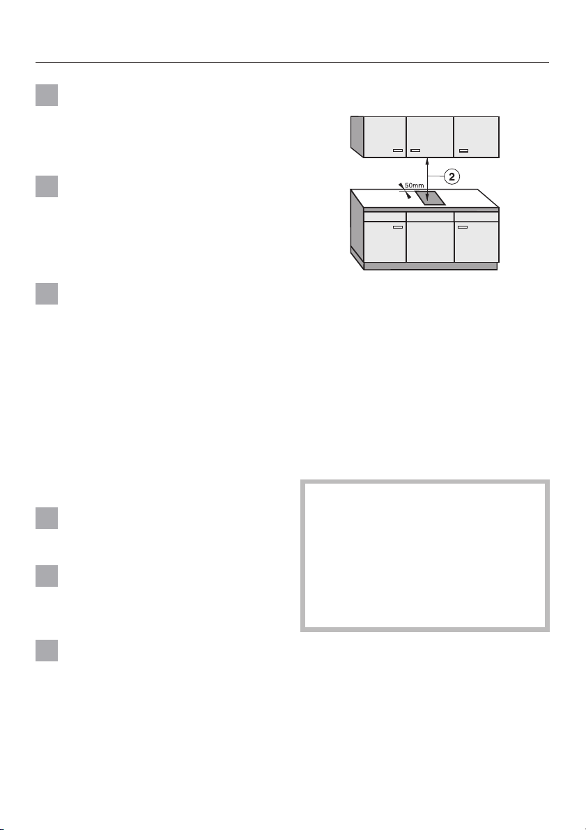
Safety distance above the appliance
-
-
A minimum safety distance b must be
maintained between the hob and the
cooker hood above it. See the manufacturer’s operating and installation instructions for details. For any flammable
objects, e.g utensil rails, wall units etc.
a minimum safety distance of at least
760 mm should be maintained between
it and the hob below.
When two or more appliances are in
stalled together below a cooker
hood, e.g. a ceramic combiset and
a gas wok combiset, which have dif
ferent safety distances given in their
-
installation instructions you should
select the greater distance of the
two.
-
-
Spray canisters, aerosols and other
inflammable substances should not
be stored in a drawer under the hob.
4
Page 5

Warning and Safety instructions
Safety distance between the KM 410 /
KM 411 and a cooker hood above it
For safety reasons, the minimum
safety distance between the KM 410
KM 411 Open grill and a cooker
hood above it, is the same as for
gas hobs, i.e. 650 mm.
The KM 410 / KM 411 should not
be used in conjunction with a
cooker hood that uses paper or carbon
filters.
The KM 410 / KM 411 should not
be used with a recirculating cooker
hood.
When placing the KM 410 / KM 411
below a cooker hood, the outlet
system of the cooker hood must be metallic throughout its length and be heat
proof.
The cooker hood outlet ducting
must be in compliance with national and local building regulations.
All grease filters must be cleaned
regularly and active charcoal filters
replaced regularly. Fat build up in the
filters is a potential fire hazard.
Never leave the grill unattended
when in use. It is possible for the
food being grilled to catch fire.
All dimensions in this instruction book
are given in mm.
Keep these instructions in a safe place
and pass them on to any future user.
Should any additional mechanical
ventilation be present then the ef
fect of this additional ventilation on the
combustion and flame performance of
any existing appliances must be deter
mined before any cooking appliances
are used.
-
-
5
Page 6

Appliance dimensions
KM 400 / KM 408-1 / KM 412
a Spring clamps
6
Page 7

KM 402
Appliance dimensions
a Spring clamps
b Drain tap
7
Page 8

Appliance dimensions
KM 410 / KM 411
a Spring clamps
b Drain tap
8
Page 9

KM 418
Appliance dimensions
a Spring clamps
9
Page 10

Worktop cut-out
Installing one or more appliances
Dimensions 7 mm and 11 mm are the
space taken up by the frame of the ap
pliance on the worktop.
^ Make a cut-out for the hob in the
worktop, paying attention to the appliance height. See section “Appliance dimensions”.
Dimension “B” applies to a combination
of appliances and is shown on the
chart.
There must be a minimum safety distance of 50 mm between the appliance
and the back wall and the following dis
tances from a side wall to the right or
left of the appliance:
KM 400, KM 402, KM 412
KM 418 = 40 mm
KM 408-1 = 50 mm
KM 410 / KM 411 = 250 mm
See also chapter “Warning and Safety
Instructions”.
Cut out the worktop according to the di
mensions listed in the following chart.
Worktop cut-out
-
Number of
appliances
1
1
3
4
5
6
7
Depth
in mm
± 1 mm
500
500
500
500
500
500
500
(= Dim. B)
Important:
The maximum tolerance for the worktop
cut-out must not exceed ± 1 mm.
When building in several combiset
appliances a spacer bar must be fitted between each unit.
See chapter “Fitting the spacer bars
and spring clamps”.
-
Width
in mm
± 1 mm
266
554
842
1130
1418
1706
1994
^
Seal the cut surfaces with a suitable
sealant to avoid swelling caused by
moisture.
The materials used must be heat re
sistant.
10
-
Page 11

Fitting the spacer bars and
spring clamps
Installation
a Spring clamps
b Spacer bars
Installation of several appliances
The illustration above shows an exam
ple of a worktop cut-out with spacer
bars b and spring clamps a for 3 ap
pliances.
For more than 3 appliances, repeat di
mension 288 mm.
The worktop cut-out dimensions for
several appliances are shown in the ta
ble on the previous page.
c Gap between spacer bar and
worktop
^
-
-
-
Fix the spacer bars b and the spring
clamps a provided to the positions
indicated. See chapter “Fixing the
spacer bars” and “Fixing the spring
clamps”.
For the installation of gas appliances
see respective installation instruc
tions.
-
11
Page 12

Installation
Fixing the spacer bars
^ Position the spacer bars b in the po-
sitions shown in “Fitting the spacer
bars and spring clamps” so they are
flush with the top edge of the cut-out,
and secure with the 3.5 x 25 mm
screws supplied.
^ Then fill in gap c between the bars
and the worktop with silicone from
the tube supplied.
Fixing the spring clamps
^ Position the spring clamps a in the
positions shown in “Fitting the spacer
bars and spring clamps” so that they
are flush with the top edge of the
cut-out, and secure with the
3.5 x 25 mm screws supplied.
Granite worktops
Granite worktops
^
With granite worktops the spacer
bars b must be positioned and se
cured with strong double-sided adhe
sive tape. In addition, coat the edges
with silicone and fill in gap c.
The screws are not required for granite
worktops.
12
-
^
With granite worktops, the spring
clamps a must be positioned and
secured with strong double-sided ad
hesive tape. In addition, coat the
edges with silicone.
-
The screws are not required for granite
worktops.
-
Page 13

Installation
Building in the appliance
Guide the hob electric cable down through the cut-out and connect the appli
^
ance to the electricity supply.
^ Position the hob. Then with a hand on each side of the hob, press down on the
fixing points of the spring clamps a on the top and bottom edges until it clicks
into place. When doing this take care that the seal of the hob is lying flat above
the worktop on all sides. This is important to ensure an effective seal on all
sides.
-
The hob can now only be removed with a special tool.
13
Page 14

General
Important
Under no circumstances should
sealant find its way between the
frame of the top part of the hob and
the worktop.
This could cause difficulties if the
hob ever needs to be taken out for
servicing, (possibly leading to dam
age to the frame and worktop).
The sealing strip under the edge of the
top part of the hob provides a sufficient
seal for the worktop.
-
14
Page 15

All electrical work should be carried
out by a suitably qualified and com
petent person in strict accordance
with national and local safety regula
tions.
Electrical connection
Important
The wires in the mains lead are col
oured in accordance with the following
code:
Green/yellow = earth
-
For extra safety it is advisable to install
a residual current device (RCD), with a
trip current of 30 mA.
Connection for each appliance should
be made via a suitable isolator.
The data plate gives the necessary
data for connection.
WARNING
THIS APPLIANCE MUST BE
EARTHED
Blue = neutral
Brown = live
As the colours of the wires in the mains
lead of this appliance may not corre
spond with the coloured markings iden
tifying the terminals in your plug pro
ceed as follows:
^ The wire which is coloured green and
yellow must be connected to the terminal in the plug which is marked
with the letter E or by the earth symbol - or coloured green or green
and yellow.
^ The wire which is coloured blue must
be connected to the terminal which is
marked with the letter N or coloured
black.
^
The wire which is coloured brown
must be connected to the terminal
which is marked with the letter A or
coloured red.
-
-
-
15
Page 16

Alteration rights reserved 00/3901
This paper consists of cellulose which has been bleached without the use of chlorine.
 Loading...