

Page 1
Installation Instructions
Ceramic hobs
KM 400 / 400-3 / 412 / 418 / 418-1
Ceramic contact grill
KM 408-1 / 408-2
Open grill KM 410 / 411 / 411-3
Deep fat fryer KM 402 / 403
To avoid the risk of accidents
or damage to the machine
it is essential to read these
instructions before it is
installed and used for the first time.
en-GB
M.-Nr. 04 930 397
Page 2

Contents
Warning and Safety instructions . . . . . . . . . . . . . . . . . . . . . . . . . . . . . . . . . . . . . 3
Building in ........................................................3
Additional safety notes on induction hobs / KM 418 / KM 418-1 ............4
Safety distance above the appliance .................................5
Safety distance between the KM 410 / KM 411 / KM 411-3 and a cooker hood
above it ........................................................5
Appliance dimensions. . . . . . . . . . . . . . . . . . . . . . . . . . . . . . . . . . . . . . . . . . . . . . 6
KM 400 / KM 400-3 / KM 408-1 / KM 408-2 / KM 412 .......................6
KM402/KM403...................................................7
KM 410 / KM 411 / KM 411-3..........................................8
KM 418 / KM 418-1 .................................................9
Worktop cut-out . . . . . . . . . . . . . . . . . . . . . . . . . . . . . . . . . . . . . . . . . . . . . . . . . . 10
Installation . . . . . . . . . . . . . . . . . . . . . . . . . . . . . . . . . . . . . . . . . . . . . . . . . . . . . . 11
Fitting the spacer bars and spring clamps ..............................11
Fixing the spacer bars ..............................................12
Granite worktops................................................12
Fixing the spring clamps ............................................12
Granite worktops................................................12
Building in the appliance ............................................13
General . . . . . . . . . . . . . . . . . . . . . . . . . . . . . . . . . . . . . . . . . . . . . . . . . . . . . . . . . 14
Electrical connection . . . . . . . . . . . . . . . . . . . . . . . . . . . . . . . . . . . . . . . . . . . . . 15
2
Page 3
Warning and Safety instructions
Building in
Fit wall units and the cooker hood
before fitting the ceramic hob, to
avoid damaging the hob.
The veneer or laminate coatings of
~
worktops (or adjacent kitchen units)
must be treated with 100 °C heat
resistant adhesive which will not
dissolve or distort. Any backmoulds
must be of heat-resistant material.
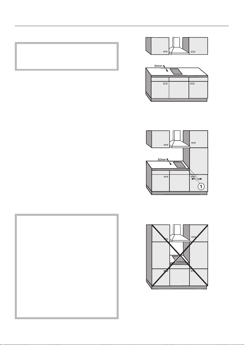
Ideally the hobs should be installed
~
with plenty of space on either side.
There may by a wall at the rear and a
wall or tall unit at one side. On the other
side, however, no unit or divider may
stand higher than the hob (see
illustrations).
An electric fryer must not be
~
installed next to a gas hob, as the gas
flames could ignite the fat in the fryer. It
is essential to maintain a safety
distance of at least 288 mm between
these two appliances.
recommended
not recommended
Due to the heat radiated by the hob
and to allow cooking fumes to
dissipate it is essential that a
minimum safety distance a is
maintained between the worktop
cut-out and adjacent kitchen units,
e.g. a tall unit, as follows:
40 mm = KM 400, 400-3, 402,
403, 412, 418, 418-1
50 mm = 408-1, 408-2
250 mm = KM 410, 411, 411-3
There must be a minimum safety
distance of 50 mm between the hob
and a back wall.
not allowed!
3
Page 4

Warning and Safety instructions
After installation of the hob ensure
~
that the connection cable is without
hindrance and that there is no
mechanical obstruction which could
damage it, such as a drawer.
These appliances must not be
~
installed over a dishwasher, washing
machine, tumble dryer, refrigerator,
fridge-freezer or freezer. The high
temperatures radiated by hobs could
damage the appliance below.
This equipment may only be used in
~
mobile installations such as ships,
caravans, aircraft etc. if a risk
assessment of the installation has been
carried out by a suitably qualified
engineer.
Spray canisters, aerosols and other
~
inflammable substances should not be
stored in a drawer under the hob.
Additional safety notes on induction
hobs / KM 418 / KM 418-1
This hob must not be installed
~
above an oven or cooker unless these
have a built-in cooling down fan.
To ensure adequate ventilation for
~
the electronic unit on the hob an interim
shelf must not be fitted underneath
hobs with induction heating.
4
Page 5
Warning and Safety instructions
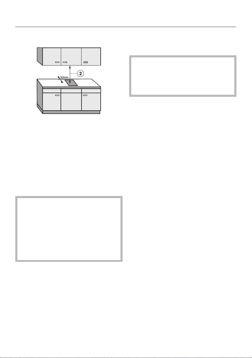
Safety distance above the appliance
A minimum safety distance b must be
maintained between the hob and the
cooker hood above it. See the
manufacturer’s operating and
installation instructions for details. For
any flammable objects, e.g utensil rails,
wall units etc. a minimum safety
distance of at least 760 mm should be
maintained between it and the hob
below.
When two or more appliances are
installed together below a cooker
hood, e.g. a combiset and a gas
wok combiset, which have different
safety distances given in their
installation instructions you should
select the greater distance of the
two.
Safety distance between the KM 410 /
KM 411 / KM 411-3 and a cooker
hood above it
For safety reasons, the minimum
safety distance between the KM410/
KM 411 / KM 411-3 Open grill and a
cooker hood above it, is the same as
for gas hobs, i.e. 650 mm.
The KM 410, 411, 411-3 should not
~
be used in conjunction with a cooker
hood that uses paper or carbon filters.
The KM 410, 411, 411-3 should not
~
be used with a recirculating cooker
hood.
When placing the KM 410, 411,
~
411-3 below a cooker hood, the outlet
system of the cooker hood must be
metallic throughout its length and be
heat proof.
The cooker hood outlet ducting must
~
be in compliance with national and
local building regulations.
Should any additional mechanical
~
ventilation be present then the effect of
this additional ventilation on the
combustion and flame performance of
any existing appliances must be
determined before any cooking
appliances are used.
All grease filters must be cleaned
~
regularly. Fat build up in the filters is a
potential fire hazard.
Never leave the grill unattended
~
when in use. It is possible for the food
being grilled to catch fire.
All dimensions in this instruction book
are given in mm.
Keep these instructions in a safe place
and pass them on to any future user.
5
Page 6
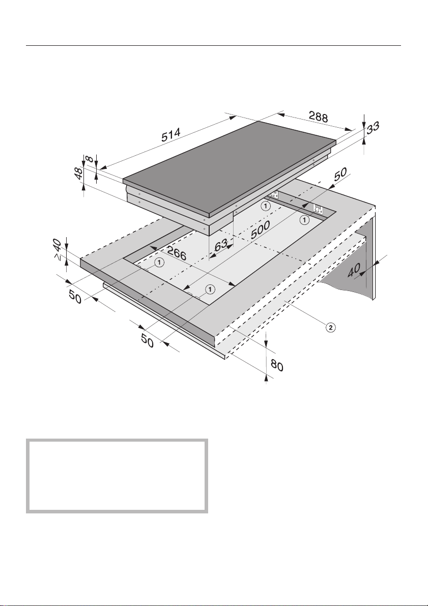
Appliance dimensions
KM 400 / KM 400-3 / KM 408-1 /
KM 408-2 / KM 412
a Spring clamps
b Protective shelf
(KM 408-1 / KM 408-2 only)
A protective shelf and a front panel
must be fitted underneath KM 408-1
and KM 408-2 to ensure that the
underside of the appliance is not
accessible after installation.
6
Ensure that the connection cable
~
cannot come into contact with the
underside of the appliance.
A minimum distance of 80 mm is
~
required between the upper surface of
the worktop and the protective shelf
A gap of 40 mm must be maintained
~
between the shelf and the rear wall.
Page 7

KM 402 / KM 403
Appliance dimensions
a Spring clamps
b Drain tap
7
Page 8

Appliance dimensions
KM 410 / KM 411 / KM 411-3
a Spring clamps
b Drain tap
8
Page 9

KM 418 / KM 418-1
Appliance dimensions
a Spring clamps
b Building-in depth
c Front
d Building-in depth - mains connection box
9
Page 10

Worktop cut-out
Seal the cut surfaces with a suitable
^
sealant to avoid swelling caused by
moisture. The materials used must be
heat resistant.
Worktop cut-out
Number of
appliances
Depth
in mm
±1mm
Width
(=Dim. B)
in mm
±1mm
Dimensions 7 mm and 11 mm are the
space taken up by the frame of the
appliance on the worktop.
^ Make a cut-out for the hob in the
worktop, paying attention to the
appliance height. See section
"Appliance dimensions".
Dimension "B" applies to a combination
of appliances and is shown on the
chart.
Due to the heat radiated by the hob
and to allow cooking fumes to
dissipate it is essential that a
minimum safety distance is
maintained between the worktop
cut-out and adjacent kitchen units,
e.g. a tall unit. See Warning and
Safety instructions.
1
2
3
4
5
6
7
500
500
500
500
500
500
500
266
554
842
1130
1418
1706
1994
Important:
The maximum tolerance for the worktop
cut-out must not exceed±1mm.
When building in several combiset
appliances a spacer bar must be
fitted between each unit. (See
"Fitting the spacer bars and spring
clamps").
10
Page 11

Fitting the spacer bars and
spring clamps
Installation
a Spring clamps
b Spacer bars
Installation of several appliances
The illustration above shows an
example of a worktop cut-out with
spacer bars b and spring clamps a
for 3 appliances.
For more than 3 appliances, repeat
dimension 288 mm.
The worktop cut-out dimensions for
several appliances are shown in the
table on the previous page.
c Gap between spacer bar and
worktop
^
Fix the spacer bars b and the spring
clamps a provided to the positions
indicated. See "Fixing the spacer
bars" and "Fixing the spring clamps".
11
Page 12

Installation
Fixing the spacer bars
d
c
^ Position the spacer bars b in the
positions shown in "Fitting the spacer
bars and spring clamps" so they are
flush with the top edge of the cut-out,
and secure with the 3.5 x 25 mm
screws supplied.
^ Then fill in gap c between the bars
and the worktop with silicone from
the tube supplied.
Fixing the spring clamps
^ Position the spring clamps a in the
positions shown in "Fitting the spacer
bars and spring clamps" so that they
are flush with the top edge of the
cut-out, and secure with the 3.5 x
25 mm screws supplied.
Granite worktops
Granite worktops
With granite worktops the spacer bars
b must be positioned and secured with
strong double-sided adhesive tape. In
addition, coat the edges with silicone
and fill in gap c.
The screws are not required for granite
worktops.
12
With granite worktops, the spring
clamps a must be positioned and
secured with strong double-sided
adhesive tape. In addition, coat the
edges with silicone.
The screws are not required for granite
worktops.
Page 13

Installation
Building in the appliance
Guide the hob electric cable down through the cut-out and connect the
^
appliance to the electricity supply.
^ Position the hob. Then with a hand on each side of the hob, press down on the
fixing points of the spring clamps a on the top and bottom edges until it clicks
into place. When doing this take care that the seal of the hob is lying flat above
the worktop on all sides. This is important to ensure an effective seal on all
sides.
The hob can now only be removed with a special tool.
13
Page 14

General
Important
Under no circumstances should
sealant find its way between the
frame of the top part of the hob and
the worktop.
This could cause difficulties if the
hob ever needs to be taken out for
servicing, (possibly leading to
damage to the frame and worktop).
The sealing strip under the edge of
the top part of the hob provides a
sufficient seal for the worktop.
14
Page 15

All electrical work should be carried
out by a suitably qualified and
competent person in strict
accordance with current local and
national safety regulations (BS 7671
in the UK).
Electrical connection
Connection for each appliance should
be made via a suitable isolator or a
double pole fused spur connection unit
which complies with national and local
safety regulations and the on/off switch
should be easily accessible after the
appliance has been built in.
If the connection cable is damaged,
it must be replaced by a special
connection cable. Please contact
the Miele Service / Spare Parts
Department.
Installation, repairs and other work
by unqualified persons could be
dangerous. The manufacturer
cannot be held liable for
unauthorised work.
Ensure power is not supplied to the
appliance until after installation or
repair work has been carried out.
The appliance must only be
operated when built-in. This is to
ensure that all electrical parts are
shielded. Live parts must not be
exposed.
Do not connect the appliance to the
mains electricity supply by an
extension lead. These do not
guarantee the required safety of the
appliance.
If the switch is not accessible after
installation (depending on country) an
additional means of disconnection must
be provided for all poles.
For extra safety it is advisable to install
a residual current device (RCD) with a
trip current of 30 mA.
When switched off there must be an
all-pole contact gap of 3 mm in the
isolator switch (including switch, fuses
and relays).
Important U.K.
This appliance is supplied for
connection to a single phase 230-240 V
50 Hz supply with a 3-core cable.
The wires in the mains lead are
coloured in accordance with the
following code:
Green/yellow = earth
Blue = neutral
Brown = live
WARNING
THIS APPLIANCE MUST BE
EARTHED
Please make sure that the connection
data quoted on the data plate match
the household mains supply.
15
Page 16

Electrical connection
Important
The electrical safety of this appliance
can only be guaranteed when
continuity is complete between the
appliance and an effective earthing
system, which complies with local and
national regulations. It is most important
that this basic safety requirement is
present and tested regularly and if
there is any doubt the electrical wiring
in the home should be inspected by a
qualified electrician. The manufacturer
cannot be held liable for the
consequences of an inadequate
earthing system such as an electric
shock.
The manufacturer cannot be held
liable for damage which is the direct
or indirect result of incorrect
installation or connection.
161718
Page 17

Page 18

Page 19

19
Page 20

Alteration rights reserved / 3707
M.-Nr. 04 930 397 / 01
 Loading...