


Installation instructions
Gas-cooktops
To avoid the risk of accident or damage to the appliance it is essential to
read these instructions before installing or using it.
M.-Nr. 05 827 691en - AUS

WO This appliance can be used in countries other than those specified on
the appliance. It is, however, set up for connection to the gas and electricity
supplies in the countries specified. For use in other countries, please contact
Miele in your country.
2

Contents
Warning and Safety instructions . . . . . . . . . . . . . . . . . . . . . . . . . . . . . . . . . . . . . 4
Appliance dimensions and worktop cut-out . . . . . . . . . . . . . . . . . . . . . . . . . . . . 7
KM370...........................................................7
KM 370-1 .........................................................8
KM371...........................................................9
KM390..........................................................10
KM391..........................................................11
Installation . . . . . . . . . . . . . . . . . . . . . . . . . . . . . . . . . . . . . . . . . . . . . . . . . . . . . . 12
Securing the appliance .............................................13
General installation tips .............................................14
Electrical connection . . . . . . . . . . . . . . . . . . . . . . . . . . . . . . . . . . . . . . . . . . . . . 15
Gas connection . . . . . . . . . . . . . . . . . . . . . . . . . . . . . . . . . . . . . . . . . . . . . . . . . . 16
Nominal Rating Table . . . . . . . . . . . . . . . . . . . . . . . . . . . . . . . . . . . . . . . . . . . . . 18
Conversion to another type of gas. . . . . . . . . . . . . . . . . . . . . . . . . . . . . . . . . . . 19
KM 370 / KM 370-1 / KM 371.........................................19
Jet table ......................................................19
Changing the main jets...........................................20
Changing the low setting jets ......................................22
After conversion ................................................23
KM390/KM391..................................................24
Jet table ......................................................24
Changing the main jets...........................................25
Changing the low setting jets ......................................27
After conversion ................................................29
3
Warning and Safety instructions
Ensure that the gas pipe and
Fit the wall units and rangehood
before fitting the cooktop to avoid
damaging the surface.
Do not modify this appliance.
~
This appliance must not be
~
connected to a gas flue. It must be
installed and connected in accordance
with current installation regulations.
The room in which the gas cooktop
~
is installed must be at least 20 m
size with a door or window in it which
can be opened to the outside air.
The veneer or laminate coatings of
~
worktops (or adjacent kitchen units)
must be treated with 100 °C
heat-resistant adhesive which will not
dissolve or distort.
Any backmoulds must be of
heat-resistant material.
An electric fryer must not be
~
installed directly next to a gas cooktop,
as the gas flames could ignite the fat in
the fryer. It is essential to maintain a
distance of at least 300 mm between
these two appliances.
3
in
~
electrical cable are installed in such a
way that they do not touch any parts of
the appliance which become hot. This
could cause damage.
The electrical cable and a flexible
~
gas connection pipe must be installed
in such a way so that they do not come
into contact with any moving kitchen
parts (e.g. a drawer), and cannot
become trapped.
Observe carefully the safety
~
distances given on the following pages.
Do not use or store flammable
~
materials in the appliance storage
drawer or near this appliance.
Do not spray aerosols in the vicinity
~
of this appliance while it is in operation.
Do not use the appliance to heat up
~
the room. Due to the high temperatures
radiated, objects near the appliance
could catch fire.
All dimensions in this instruction booklet
are given in mm.
The appliance may be installed
~
above a Miele oven, if the work-top is at
least 40 mm thick.
A gas cooktop may not be built in
~
over a fridge, fridge freezer, freezer,
dishwasher, washing machine or
tumble dryer.
This appliance must not be installed
~
and used in mobile installations such as
ships etc.
4
,
This appliance must be installed
and connected to services in
accordance with local and national
safety and building regulations.
Warning and Safety instructions
Safety clearance above the cooktop
A minimum safety clearance must be
maintained between the cooktop and
the rangehood above it. See the
rangehood manufacturer's operating
and installation instructions for details.
If the manufacturer's instructions are
not available for the rangehood, a
minimum safety clearance of at least
760 mm above the burner cap must be
maintained. For any flammable objects,
e.g. utensil rails, wall units etc. a
minimum clearance of at least 760 mm
above the burner cap must be
maintained between them and the
cooktop below.
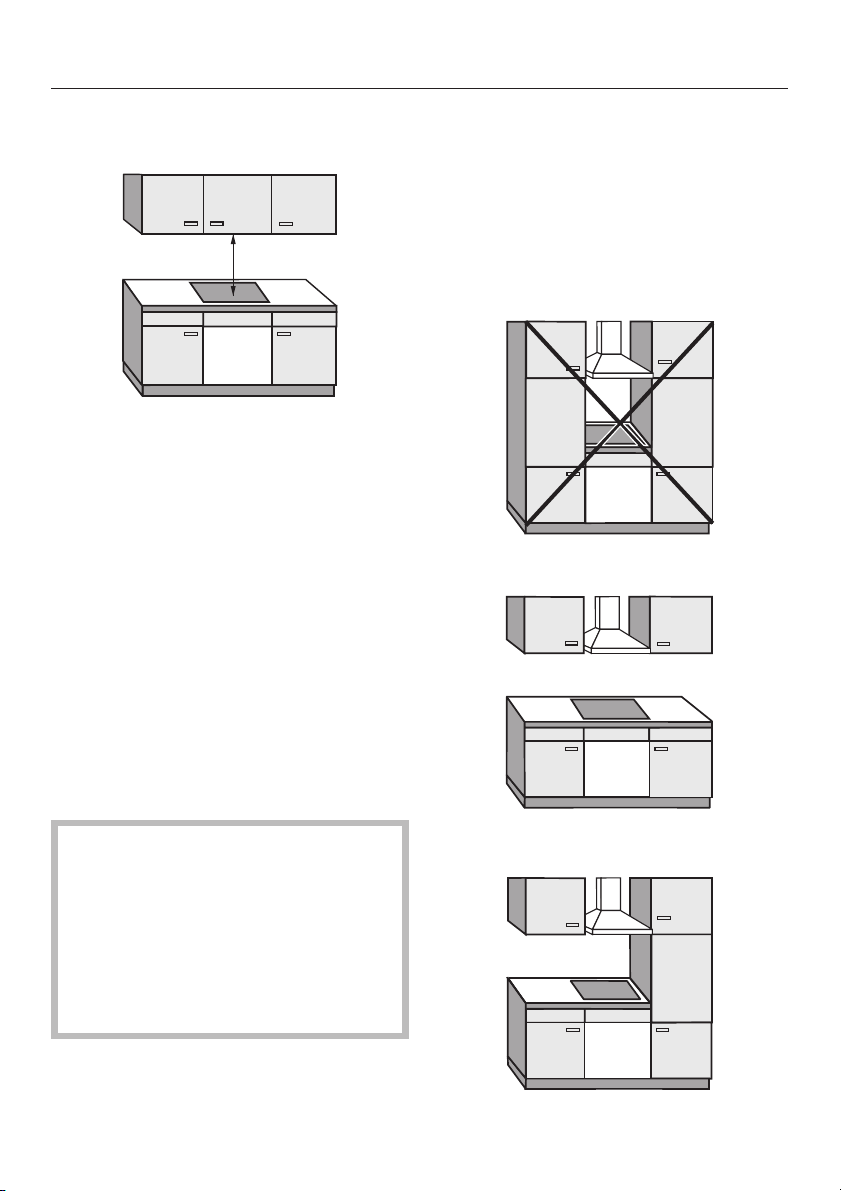
Side / rear clearances to the cooktop
Ideally the cooktop should be installed
with plenty of space on either side.
There may be a wall at the rear and a
tall unit or wall at one side. On the other
side, however, no unit or divider should
stand higher than the cooktop (see
illustrations).
Not allowed
When two or more appliances are
installed together below a
rangehood, e.g. a gas cooktop and
an induction cooktop combiset,
which have different safety
clearances given in the installation
instructions, you should select the
greater clearance of the two.
Recommended
Not recommended
5
Warning and Safety instructions
Before installing the appliance, check
that the location provides the required
clearances from combustible material
and, if necessary, provide protection to
adjacent surfaces as required by
regulations.
A gas appliance shall be installed such
that the surface temperature of any
nearby combustible surface* will not
exceed 65 °C above ambient.
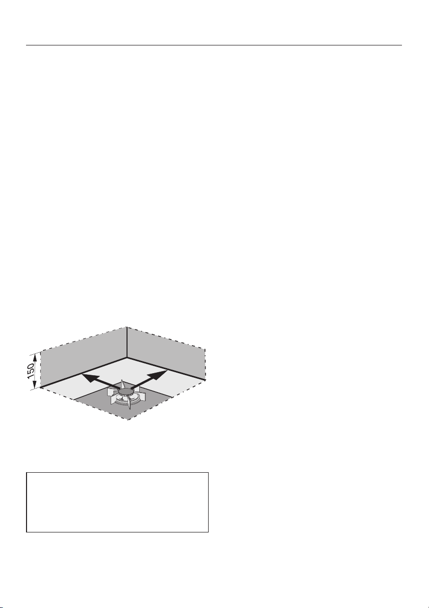
The minimum clearance from a
combustible surface shall be a 200 mm
horizontal distance from the periphery
of any gas burner (AS 5601).
If that horizontal clearance is less than
200 mm, that vertical surface must be
protected by a non-combustible
material for 150 mm above the cooktop
surface across the entire length (depth,
width).
The shown area indicates the protected
surface, which may be ceramic tiles or
other approved material.
*Combustible surface:
A material which will ignite and burn,
and includes material which has
been flameproofed.
6
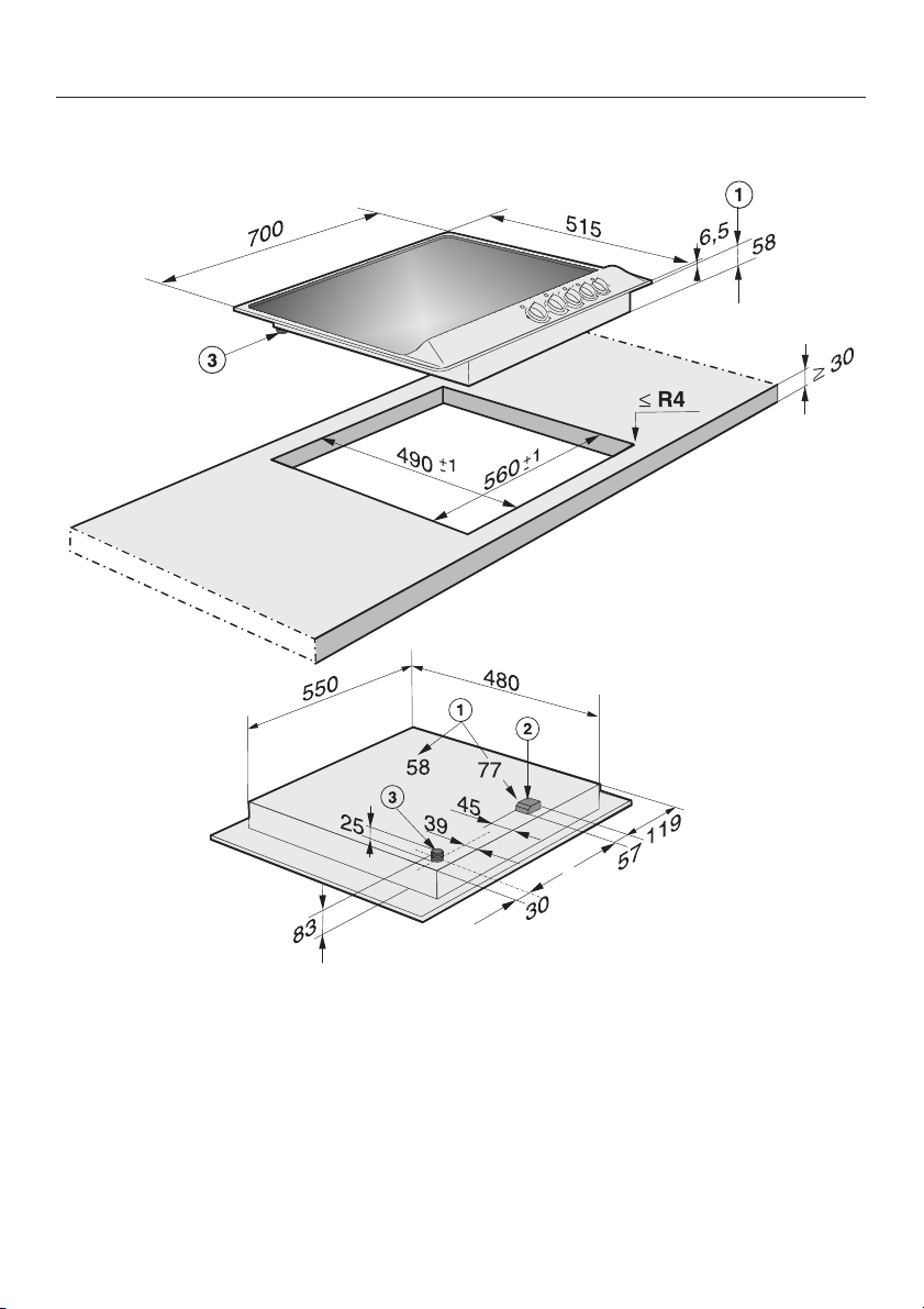
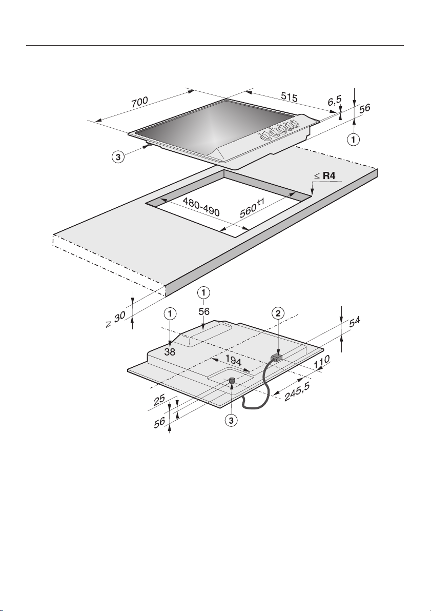
KM 370
Appliance dimensions and worktop cut-out
a Building-in height
b Connection box
c Gas connection R
1
/2- ISO 7-1
7
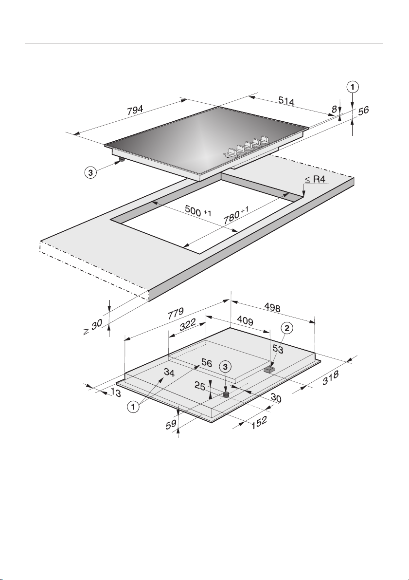
Appliance dimensions and worktop cut-out
KM 370-1
a Building-in height
b Connection box
c Gas connection R
8
1
/2- ISO 7-1
KM 371
Appliance dimensions and worktop cut-out
a Building-in height
b Connection box
c Gas connection R
1
/2- ISO 7-1
9
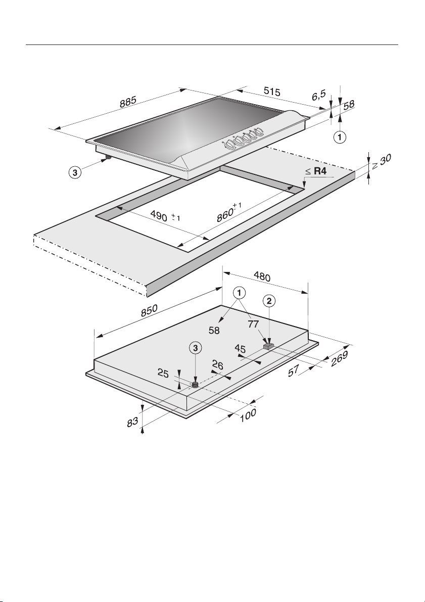
Appliance dimensions and worktop cut-out
KM 390
a Building-in height
b Connection box
c Gas connection R
10
1
/2- ISO 7-1

KM 391
Appliance dimensions and worktop cut-out
a Building-in height
b Connection box
c Gas connection R
1
/2- ISO 7-1
11

Installation
Make the worktop cut-out following
^
the dimensions applicable.
Remember to maintain the minimum
safety distances (See "Safety
clearances".
Seal the cut surfaces with a suitable
^
heat-resistant sealant to avoid
swelling caused by moisture.
Feed the connection cable down
^
through the cut-out.
Place the cooktop in the cut-out
^
without securing it.
If the seals on the corners of the
frame are not flush with the worktop
surface, the corner radius (ß R4) can
be carefully scribed to fit.
^ Connect the cooktop to the mains
(see "Electrical connection").
^ Connect the appliance to the gas
supply (see "Gas connection").
12

Securing the appliance
KM371G/KM391G
Secure the gas cooktop at the front
^
and rear with fixing brackets a
supplied as shown.
KM370G/KM370-1G/KM390G
Secure the gas cooktop at the front
^
with fixing brackets a and rear with
fixing brackets b supplied as shown.
Tighten the screws until seal c sits
flush with the worktop.
Installation
13

Installation
General installation tips
Sealant
Do not use any sealant unless
expressly instructed to do so. The
sealing strip under the edge of the top
part of the cooktop provides a sufficient
seal for the worktop.
Do not use sealant between the
frame of the top part of the cooktop
and the worktop.
This could cause difficulties if the
cooktop ever needs to be taken out
for servicing and possibly result in
damage to the frame or the worktop.
Tiled worktop
The grouting a and the shaded area
underneath the cooktop frame must be
smooth and even so that the frame sits
evenly and the sealing strip underneath
the top part of the cooktop provides a
sufficient seal for the worktop.
Tiled worktops must be a minimum
of 5 mm thick to ensure the surface
temperatures of the combustible
surfaces underneath the tiles do not
exceed 50 K above ambient.
14

All electrical work should be carried
out by a suitably qualified and
competent person in strict
accordance with national and local
safety regulations.
Electrical connection
Important
The wires in the mains lead are
coloured in accordance with the
following code:
Green/yellow = earth
For extra safety it is advisable to install
a residual current device (RCD), with a
trip current of 30 mA.
Connection for each appliance should
be made via a suitable isolator.
The data plate gives the necessary
data for connection.
WARNING
THIS APPLIANCE MUST BE
EARTHED
Blue = neutral
Brown = live
As the colours of the wires in the mains
lead of this appliance may not
correspond with the coloured markings
identifying the terminals in your plug
proceed as follows:
^ The wire which is coloured green and
yellow must be connected to the
terminal in the plug which is marked
with the letter E or by the earth
symbol - or coloured green or
green and yellow.
^ The wire which is coloured blue must
be connected to the terminal which is
marked with the letter N or coloured
black.
^
The wire which is coloured brown
must be connected to the terminal
which is marked with the letter A or
coloured red.
15

Gas connection
Connection to the gas supply, or
conversion from one type of gas to
another should only be undertaken
by an approved fitter, who is
responsible for correct functioning
of the appliance when installed.
Every appliance should have its own
isolating valve.
Depending on country of destination
this appliance is set up for connection
to natural or liquid gas.
See adhesive label on the appliance:
G = NG (natural gas)
LP = ULPG (Propane/Butane)
Depending on country of destination
jets are supplied for conversion to a
different type of gas.
The gas connection must be
installed so that connection can be
made either from inside or outside
the kitchen unit, and the isolating
valve must be easily accessible and
visible (by opening one of the
kitchen unit doors, if necessary).
Check with your local gas supplier
about the type of gas and its
calorific value, and compare this
information with the type of gas
quoted on the cooktop data plate.
If the appropriate jets have not been
supplied with the appliance you will
need to contact your dealer or the
Technical Service Department.
Conversion to another type of gas is
described under the relevant Section.
16

The gas connection must be in
accordance with national and local
regulations.
The relevant building regulations
must also be observed.
Natural gas / liquid gas
The gas connection must be so sited
that it is not adversely heated when the
appliance is in operation.
Pressure Test Point a. This is provided
on the gas regulator (supplied for
natural gas).
Gas connection
Gas pressure must be set by the
approved gas fitter as shown on the
data plate:
Natural gas 1.0 kPa
ULPG (Propane/Butane) 2.75 kPa
Disconnect gauge and screw in the
^
test point screw.
When the gas cooktop has been
installed it is essential to check that
neither the gas pipe nor the
electricity cable is in contact with
hot parts of the appliance or hot gas
exhaust.
If a flexible connection is installed
the min. inner C must be 10 mm and
a maximum lenght of 1.2 m. Make
sure it does not touch moving parts
of the kitchen furniture, e.g. a
drawer.
^
Loosen the screw in the test point
until it is free in its housing. The
screw is retained in this position.
^
Connect the hose from the pressure
gauge.
^
Reassemble one of the large burners,
turn on the gas and manually light the
burners.
A full operational test and a test for
possible leakages must be carried
out by the fitter after installation.
17

Nominal Rating Table
Nominal rating for all gas types with the burner full on
Burner Gas type KM 370/ KM 370-1 /
KM 371
MJ/h g/h MJ/h g/h
Auxiliary burner NG
ULPG
Normal burner NG
ULPG
Fast burner NG
ULPG
Wok burner NG
ULPG
Total output NG
ULPG
Nominal rating at low setting
Burner Gas type KM 370 / KM 370-1 /
3.85
3.60
5.85
6.35
10.35
9.68
14.40
14.40
40.30
40.38 802
KM 371
MJ/h MJ/h
-
71
-
126
-
192
-
286
KM 390 / KM 391
3.85
3.60
5.85
6.35
10.35
9.68
16.20
14.40
42.10
40.38 802
KM 390 / KM 391
-
71
-
126
-
192
-
286
Auxiliary burner NG
ULPG
Normal burner NG
ULPG
Fast burner NG
ULPG
Wok burner NG
ULPG
Nominal ratings for ULPG are based on propane gas.
18
0.70
0.41
1.10
0.97
1.70
1.65
5.74
5.58
0.70
0.41
1.10
0.97
1.70
1.65
0.59
0.60

Conversion to another type of gas
KM 370 / KM 370-1 / KM 371
When converting to liquid gas, the
main jets and the small jets of all
burners must be changed.
Screw in the new jets according to
the following table.
Jet table
Main jet Ø Low setting jet Ø
NG
Auxiliary burner
Normal burner
Fast burner
Wok burner
ULPG
Auxiliary burner
Normal burner
Fast burner
Wok burner
The jet markings refer to 1/100 mm of the jet orifice.
0.90
1.10
1.50
1.70 / 0.70
0.52
0.70
0.87
1.00 / 0.37
0.42
0.52
0.60
1.30
0.23
0.32
0.40
0.68
19

Conversion to another type of gas
Changing the jets
Before carrying out any work on the
cooktop, disconnect the gas
cooktop from the gas supply and
the electricity supply. Depending
on the type of installation, either
withdraw the mains fuse, switch off
at the fused spur unit, or at the
socket and withdraw the plug.
Any repairs or maintenance work must
be done by a qualified and competent
person. Any damage caused by
unauthorised persons will void the
manufacturer's warranty.
Changing the main jets
Auxiliary-, Normal and Fast burner
^ Take off the pan support, the burner
cover b and the burner head d.
20
^
Using an (M7) socket spanner
unscrew the main jet e.
^
Change the main jet.

Wok burner
Conversion to another type of gas
Take off the burner cover a, burner
^
ring b and burner head c.
Loosen the screws d and take off
^
the plate.
Using an (M7) socket spanner
^
unscrew the main jets e (larger
diameter) and f (smaller diameter).
Change the main jets according to
^
the jet table.
21

Conversion to another type of gas
Changing the low setting jets
(all burners)
To change the low setting jets the
burner fastening screws which fix the
cooktop surface to the casing
underneath must first be unscrewed
and removed and the upper part of the
appliance has to be taken off.
Pull off the control knobs.
^
Take off the upper part.
^
a
Stainless steel:
Lift at the rear, slide forward and take
off.
Ceramic:
Insert the supplied tool at the corner
between the frame around the cooktop
and the cooktop casing below. Move
the tool along the gap between the
frame and casing to separate the
ceramic surface from the casing.
Warning: Do not insert the tool into
the seal between the ceramic
surface and the frame of the
cooktop as doing so will damage
the cooktop.
b
^ Take off the ignition switch a.
^ Loosen the low setting jet b with a
small screw driver.
^ Pull out the jet with a pair of pointed
pliers.
^
Install the new jet according to the jet
table and tighten.
22

Conversion to another type of gas
After conversion
Assemble all burners in the reverse
^
order and check for leaks by
operating them without the upper
part of the cooktop in place (use a
match to ignite the flame).
Take off all burner parts again.
^
Put the upper part of the cooktop in
^
place.
Screw on the burner head and
^
assemble all loose burner parts in the
correct order.
Push the control knobs back into
^
place.
Check the behaviour of the flames by
^
lighting all burners.
The flame must not go out in the lowest
setting, nor when the control is turned
quickly from a high to a low setting.
In the highest setting the flame must
have a distinctive and visible core.
Place the sticker enclosed with the
conversion kit next to the data plate
underneath the appliance
23

Conversion to another type of gas
KM 390 / KM 391
When converting to liquid gas, the
main jets and the small jets of all
burners must be changed.
Screw in the new jets according to
the following table.
Jet table
Main jet Ø Low setting jet Ø
NG
Auxiliary burner
Normal burner
Fast burner
Wok burner
ULPG
Auxiliary burner
Normal burner
Fast burner
Wok burner
The jet markings refer to 1/100 mm of the jet orifice.
0.90
1.10
1.50
1.80 / 0.76
0.52
0.70
0.87
1.00 / 0.37
0.42
0.52
0.60
0.90 / 0.40
0.23
0.32
0.40
0.52 / 0.23
24

Conversion to another type of gas
Changing the jets
Before carrying out any work on the
cooktop, disconnect the gas
cooktop from the gas supply and
the electricity supply. Depending
on the type of installation, either
withdraw the mains fuse, switch off
at the fused spur unit, or at the
socket and withdraw the plug.
Any repairs or maintenance work must
be done by a qualified and competent
person. Any damage caused by
unauthorised persons will void the
manufacturer's warranty.
Changing the main jets
Auxiliary-, Normal and Fast burner
^ Take off the pan support, the burner
cover b and the burner head d.
^
Using an (M7) socket spanner
unscrew the main jet e.
^
Change the main jet.
25

Conversion to another type of gas
Wok burner
Take off the burner cover a, burner
^
ring b and burner head c.
Loosen the screws d and take off
^
the plate.
Using an (M7) socket spanner
^
unscrew the main jets e (larger
diameter) and f (smaller diameter).
Change the main jets according to
^
the jet table.
26

Conversion to another type of gas
Changing the low setting jets
(Auxiliary-, Normal and fast burner)
To change the low setting jets the
burner fastening screws which fix the
cooktop surface to the casing
underneath must first be unscrewed
and removed and the upper part of the
appliance has to be taken off.
Pull off the control knobs.
^
Take off the upper part.
^
a
Stainless steel:
Lift at the rear, slide forward and take
off.
Ceramic:
Insert the supplied tool at the corner
between the frame around the cooktop
and the cooktop casing below. Move
the tool along the gap between the
frame and casing to separate the
ceramic surface from the casing.
Warning: Do not insert the tool into
the seal between the ceramic
surface and the frame of the
cooktop as doing so will damage
the cooktop.
b
^ Take off the ignition switch a.
^ Loosen the low setting jet b with a
small screw driver.
^ Pull out the jet with a pair of pointed
pliers.
^
Install the new jet according to the jet
table and tighten.
27

Conversion to another type of gas
Wok burner
Take off the ignition switch a.
^
Using a small screwdriver, unscrew
^
both low setting jets b and 3 in the
a
gas fitting.
Pull the jets out with a pair of pointed
^
pliers.
Select the jets as shown in the table
^
and fit, reversing the procedure, and
secure.
c
b Low setting jet with smaller orifice
(e.g. for liquid gas: 0.23).
c Low setting jet with larger orifice
(e.g. for liquid gas: 0.52).
b
28

Conversion to another type of gas
After conversion
Assemble all burners in the reverse
^
order and check for leaks by
operating them without the upper
part of the cooktop in place (use a
match to ignite the flame).
Take off all burner parts again.
^
Put the upper part of the cooktop in
^
place.
Screw on the burner head and
^
assemble all loose burner parts in the
correct order.
Push the control knobs back into
^
place.
Check the behaviour of the flames by
^
lighting all burners.
The flame must not go out in the lowest
setting, nor when the control is turned
quickly from a high to a low setting.
In the highest setting the flame must
have a distinctive and visible core.
Place the sticker enclosed with the
conversion kit next to the data plate
underneath the appliance
293031


KM 370 / KM 370-1 / KM 371 / KM 390 / KM 391
M.-Nr. 05 827 691 / 06en - AUS
 Loading...