

Page 1
Fully Integrated
36” MasterCool II
All Refrigerator:
K 2901 Vi / K 2911 Vi
All Freezer:
F 2901 Vi / F 2911 Vi
Bottom Mount:
KF 2901 Vi / KF 2911 Vi
French Door:
KF 2981 Vi
Shown: KF 2981 Vi
Please note: This information is subject to change
Specification Sheets TRS 04252019
8miele.ca
Page 2
Fully Integrated
36” MasterCool II
SPECIFICATIONS
Overall Unit Dimensions 353/4” (908 mm) W x 833/4”- 853/16” (2127 - 2164 mm) H x 24” (610 mm) D [Depth does not include door panel]
Niche
Minimum Cabinet Niche Opening 36” (915 mm) W* x 84” - 853/16” (2134 - 2164 mm) H x 243/4” (629 mm) D
Interior Volume K 29x1 Vi F 29x1 Vi KF 29x1 Vi
Refrigeration Volume ** 0 **
Freezer Volume 0 ** *
Electrical
Electrical Requirements
Power Cord NEMA 5-15 plug, 5 ft (1.52 m)
Plumbing K 29x1 Vi F 29x1 Vi KF 29x1 Vi
Water Supply Requirements -
Water Connection Line
Shipping
Shipping Weight 435 lbs (197 kg) 462 lbs (210 kg) 507 lbs (230 kg)
Shipping Dimensions 40” (1016 mm) W x 8913/16” (1,294 mm) H x 291/4” (800 mm) D
Support
Call Miele
Miele Website
20/20 Link
Please note the following:
• This specication sheet is for a single built-in unit.
• When combining multiple MasterCool units side-by-side, please refer to the Merging Kit specication sheet.
*If design calls for a partition less than 6 5/16” (160 mm) the left unit’s cutout will require an additional 1/8” (3 mm) to the width to allow installation of
the Heating Mat/Merge Kit.
K 29x1 Vi F 29x1 Vi KF 29x1 Vi
In the case of side-by-side installations, a separate outlet must be used for each appliance.
-
K 29x1 Vi F 29x1 Vi KF 29x1 Vi
110V / 120V, 60Hz, 15 Amps
Connect to a cold water supply only. Do not connect to a low-mineral or
a reverse osmosis system. Must be connected to a shut-off valve. The
water shut-off valve must be accessible after installation. The water pressure must be between 29 psi (2 bar) and 116 psi (8 bar). If the pressure is
higher than 120 psi (8.3 bar), a pressure reducing valve must be installed.
Standard 1/4” O.D flexible water line. The maximum outer diameter of the
water pipe (without fittings): 3/8” (10 mm). Water line is not included.
(800) 565-6435
8www.miele.ca
82020technologies.com
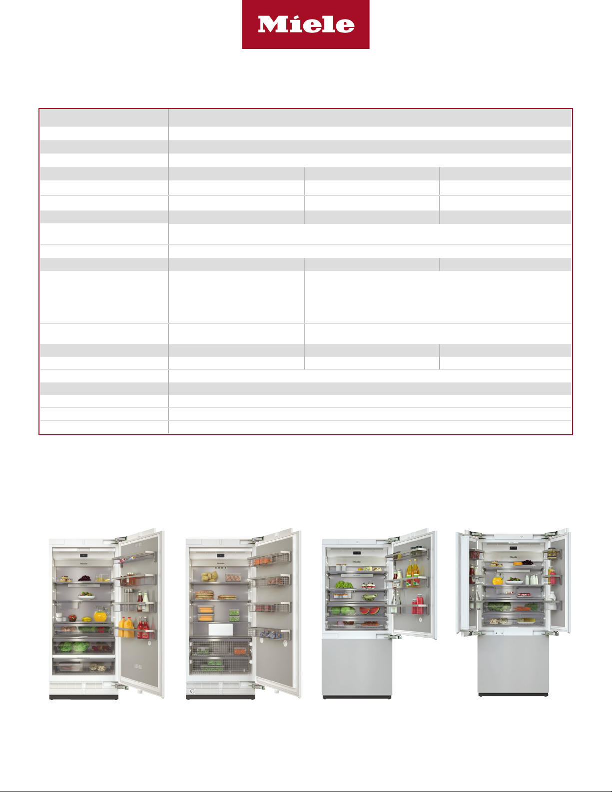
K 2901 Vi (Right Hinged)
K 2911 Vi (Left Hinged)
F 2901 Vi (Right Hinged)
F 2911 Vi (Left Hinged)
KF 2901 Vi (Right Hinged)
KF 2911 Vi (Left Hinged)
KF 2981 Vi (French Door)
Page 2 of 12
Page 3
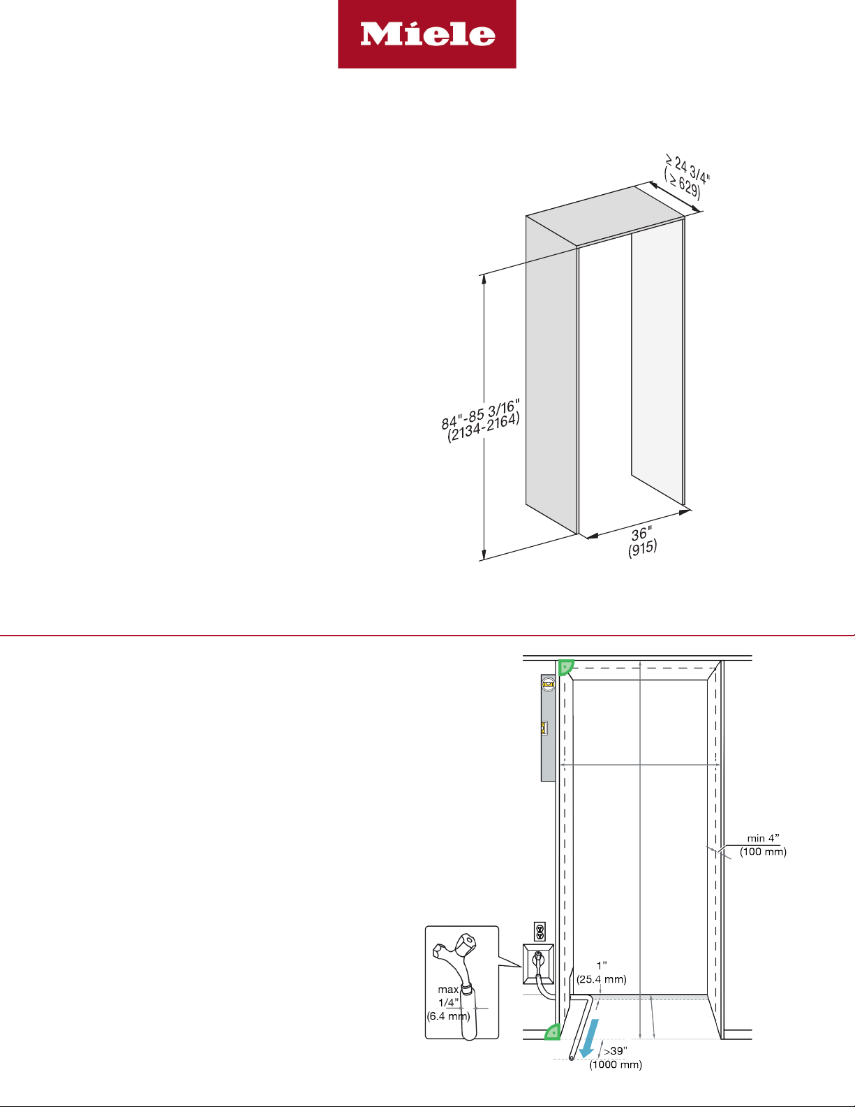
CUTOUT DIMENSIONS
• Niche depth assumes a 3/4” (19 mm) panel, please
adjust according to custom panel thickness
Fully Integrated
36” MasterCool II
CUTOUT DETAILS
• The electrical connection must not be positioned higher
than 9” (228.6 mm) above the oor.
• The 1/4” (6.4 mm) plumbed water connection should
not be positioned higher than 2” (50.8 mm) above the
oor.
Notes:
In case of an emergency the electrical outlet must be
easily accessible and must not be concealed behind the
appliance.
Page 3 of 12
Page 4
Fully Integrated
36” MasterCool II
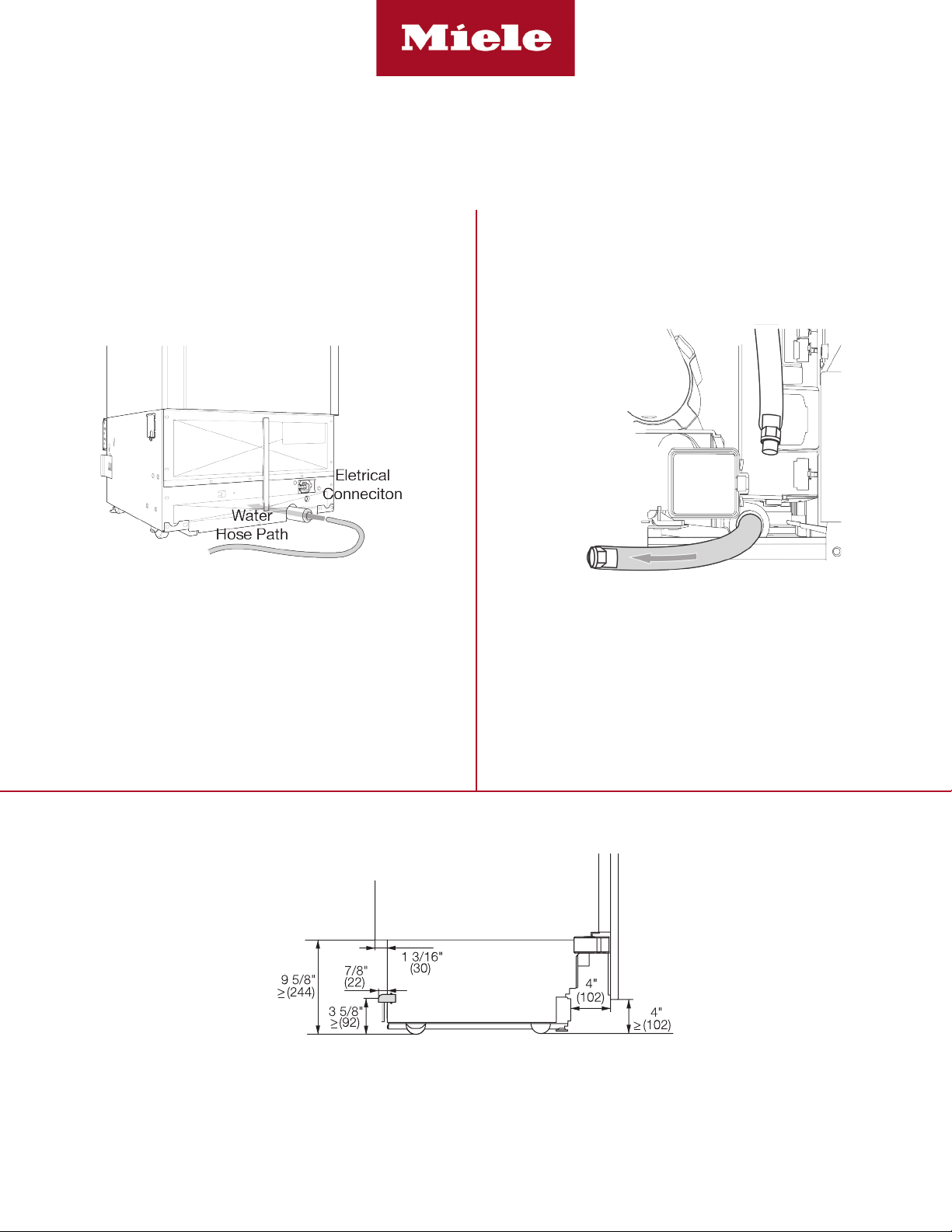
POWER SUPPLY AND WATER CONNECTION
(Water Connection For F 29x1 Vi & KF 29x1 Vi Only)
Rear View Front View
Electrical - 5 foot (1.52 m) - 120 Volt - 15 Amp
- NEMA 5-15 molded plug
Water line - 1/4” exible water line - not included
Side View
Water connection is located in front of unit.
1/4” compression tting is needed.
Electrical
Connection
Page 4 of 12
Page 5

CUSTOM PANEL INSTALLATIONS
Fully Integrated
36” MasterCool II | K 29x1 Vi & F 29x1 Vi
Minimum 35 3/4” (908 mm)
Minimum 3/4” (19 mm) outside frame
106 Pounds
Page 5 of 12
Page 6

DOOR PANEL DIMENSIONS
KFP 3604 - Door Panel
Available as an accessory
for the following models:
• K 29x1 Vi
• F 29x1 Vi
Fully Integrated
36” MasterCool II | K 29x1 Vi & F 29x1 Vi
Page 6 of 12
Page 7

CUSTOM PANEL INSTALLATIONS
Fully Integrated
36” MasterCool II | KF 2901 Vi / KF 2911 Vi
Minimum 35 3/4” (756 mm)
Minimum 3/4” (19 mm) outside frame
51 3/8” (1304 mm)
104 lbs
HOM - 51 1/2” (1307 mm) - TKH
Total height of machine. Can be adjusted
to match adjoining cabinets - typically 84”
(2133 mm).
HOM is adjustable between 84” -85 3/16”
(2134 mm - 2164 mm)
TKH =
Toe-kick height 2” - 8 3/8” (51 - 212 mm)
Lower Maximum panel weight: 22 lbs
87” (2210 mm)
84” (2134 mm)
3” (76 mm)
54 1/2” (1379 mm)
Page 7 of 12
Page 8

DOOR PANEL DIMENSIONS
KFP 3614 - Top Panel
KFP 3624 - Bottom Panel
Available as an accessory
for the following models:
• KF 2901 Vi / KF 2911 Vii
Fully Integrated
36” MasterCool II | KF 2901 Vi / KF 2911 Vi
Page 8 of 12
Page 9

CUSTOM PANEL INSTALLATIONS
Fully Integrated
36” MasterCool II | KF 2981 Vi
Minimum 17 13/16” (452.5 mm)
Minimum 35 3/4” (756 mm)
Minimum 3/4” (19 mm) outside frame
51 3/8” (1304 mm)
104 lbs
HOM - 51 1/2” (1307 mm) - TKH
Total height of machine. Can be adjusted
to match adjoining cabinets - typically 84”
(2133 mm).
HOM is adjustable between 84” -85 3/16”
(2134 mm - 2164 mm)
TKH =
Toe-kick height 2” - 8 3/8” (51 - 212 mm)
Lower Maximum panel weight: 22 lbs
87” (2210 mm)
84” (2134 mm)
3” (76 mm)
54 1/2” (1379 mm)
Page 9 of 12
Page 10

DOOR PANEL DIMENSIONS
KFP 3634 - Top Panels
KFP 3624 - Bottom Panel
Available as an accessory
for the following models:
• KF 2981 Vi
Fully Integrated
36” MasterCool II | KF 2981 Vi
HINGING DETAILS
Page 10 of 12
Page 11

HINGING DETAILS 115° OPENING
Available for the following models:
• K 29x1 Vi
• F 29x1 Vi
• KF 29x1 Vi
1-1/4” (32 mm)
1-1/2” (38 mm)
1-3/4” (44 mm)
0-3/4” (19 mm)
1” (25 mm)
Fully Integrated
36” MasterCool II
0-3/4” (19 mm)
2-5/8”
(67mm)
2-5/8”
(67mm)
2-1/3” (59mm)
2-1/3” (59mm)
2-1/24”(52mm)
2-1/24”(52mm)
1-3/8”(35mm)
1-3/8”(35mm)
1-1/6”
1-1/6”
17/24” (18mm)
17/24” (18mm)
(29.6mm)
(29.6mm)
1/4”(6.4mm)
1/4”(6.4mm)
1-3/4”(44.5mm)
1-3/4”(44.5mm)
3”(76.2mm)
3”(76.2mm)
0-1/8” (3 mm)
DOOR SWING AT 115° OPENING
Available for the following models:
• K 29x1 Vi
• F 29x1 Vi
• KF 2901 Vi / KF 2911 Vi
1-1/4” (32 mm)
1-1/2” (38 mm)
11 3/4”
(298 mm)
Max
1” (25 mm)
Page 11 of 12
Page 12

HINGING DETAILS 90° OPENING
Available for the following models:
• K 29x1 Vi
• KF 29x1 Vi
1-1/4” (32 mm)
1-3/4” (44 mm)
1-1/2” (38 mm)
2” (51 mm)
0-3/4” (19 mm)
1” (25 mm)
Fully Integrated
36” MasterCool II
7/16”
(11 mm)
1-3/16”
(30mm)
1-7/16”
(36.5mm)
1-11/16”
(43mm)
1-15/16”
(49.2mm)
0-1/8” (3 mm)
Handle or object that is
NOT ush with Cabinet
Front.
DOOR SWING AT 90° OPENING
Available for the following models:
• K 29x1 Vi
• KF 2901 Vi / KF 2911 Vi
0-3/4” (19 mm)
1” (25 mm)
1-1/4” (32 mm)
1-1/2” (38 mm)
7/16” (11 mm)
/16” (982 mm)
11
38
When installing hinge side next to an appliance or object that is within range of the door panel,
limit the door opening angle to 90°. This is done by installing the banking pin as illustrated.
Insert the banking pin through the holes and drive in with a hammer.
Specification Sheets TRS 04252019
Page 12 of 12
 Loading...