

Page 1

Fully Integrated
36” MasterCool
All Refrigerator:
K 2901 Vi / K 2911 Vi
All Freezer:
F 2901 Vi / F 2911 Vi
Bottom Mount:
KF 2901 Vi / KF 2911 Vi
French Door:
KF 2981 Vi
Shown: KF 2981 Vi
Please note: This information is subject to change
Specification Sheets TRS 05202019
8mieleusa.com
Page 2
Fully Integrated
36” MasterCool
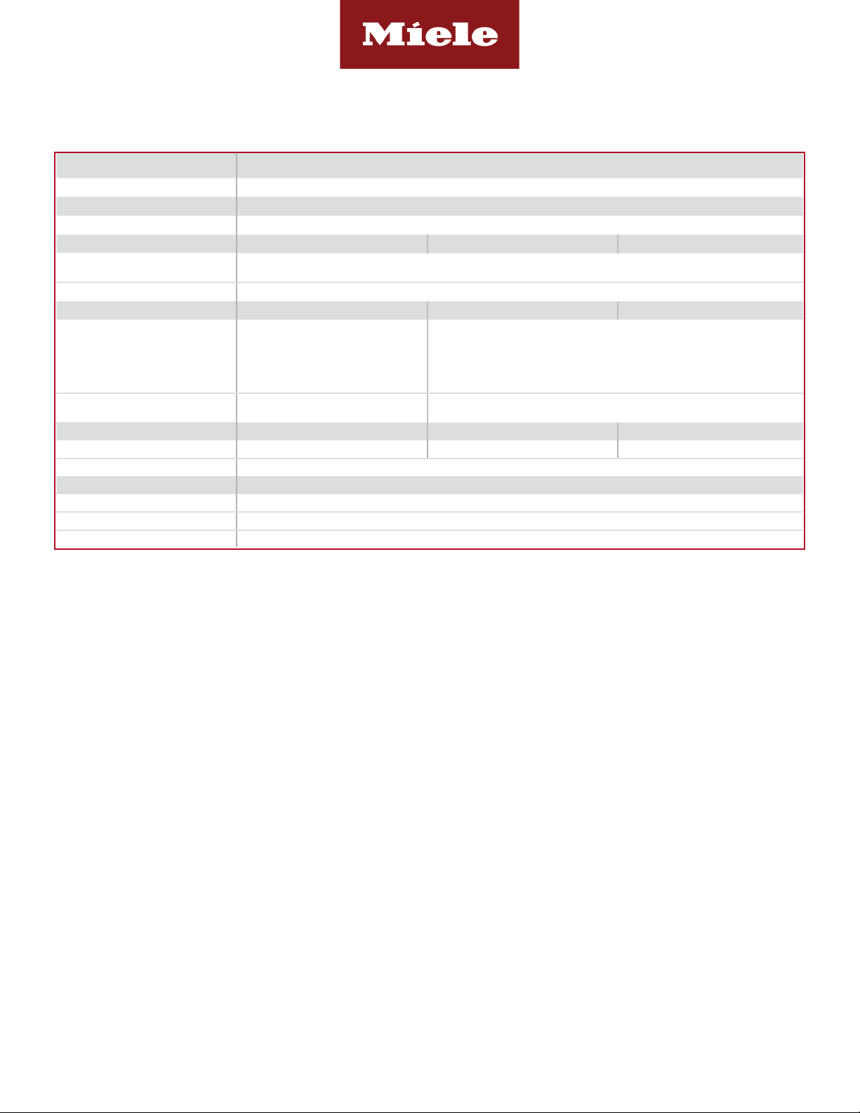
SPECIFICATIONS
3
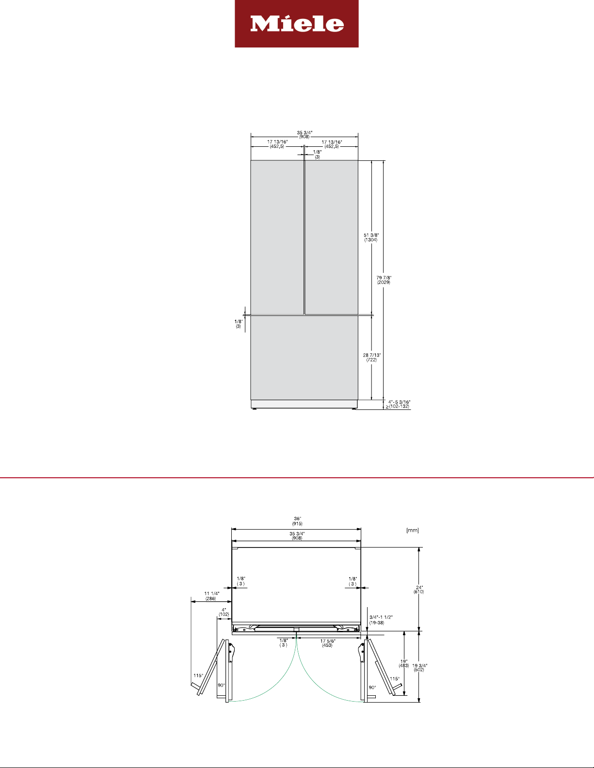
Overall Unit Dimensions 35
Niche
Minimum Cabinet Niche Opening 36” (915 mm) W* x 84” - 85
Electrical
Electrical Requirements
Power Cord NEMA 5-15 plug, 5 ft (1.52 m)
Plumbing K 29x1 Vi F 29x1 Vi KF 29x1 Vi
Water Supply Requirements -
Water Connection Line
Shipping
Shipping Weight 435 lbs (197 kg) 462 lbs (210 kg) 507 lbs (230 kg)
Shipping Dimensions 40” (1016 mm) W x 89
Support
Call Miele (800) 999-1360
Miele Website
20/20 Link
Please note the following:
• This specication sheet is for a single built-in unit.
• When combining multiple MasterCool units side-by-side, please refer to the Merging Kit specication sheet.
*If design calls for a partition less than 6 5/16” (160 mm) the left unit’s cutout will require an additional 1/8” (3 mm) to the width to allow installation of
the Heating Mat/Merge Kit.
/4” (908 mm) W x 833/4”- 853/16” (2127 - 2164 mm) H x 24” (610 mm) D [Depth does not include door panel]
3
/16” (2134 - 2164 mm) H x 243/4” (629 mm) D
K 29x1 Vi F 29x1 Vi KF 29x1 Vi
110V / 120V, 60Hz, 15 Amps
In the case of side-by-side installations, a separate outlet must be used for each appliance.
Connect to a cold water supply only. Do not connect to a low-mineral or
a reverse osmosis system. Must be connected to a shut-off valve. The
water shut-off valve must be accessible after installation. The water pressure must be between 29 psi (2 bar) and 116 psi (8 bar). If the pressure is
higher than 120 psi (8.3 bar), a pressure reducing valve must be installed.
-
Standard 1/4” O.D flexible water line. The maximum outer diameter of the
water pipe (without fittings): 3/8” (10 mm). Water line is not included.
K 29x1 Vi F 29x1 Vi KF 29x1 Vi
13
/16” (1,294 mm) H x 291/4” (800 mm) D
8www.mieleusa.com
82020technologies.com
K 2901 Vi (Right Hinged)
Item 36290101USA
K 2911 Vi (Left Hinged)
Item 36291101USA
F 2901 Vi (Right Hinged)
Item 37290101USA
F 2911 Vi (Left Hinged)
Item 37291101USA
KF 2901 Vi (Right Hinged)
Item 38290101USA
KF 2911 Vi (Left Hinged)
Item 38291101USA
KF 2981 Vi (French Door)
Item 38298101USA
Page 2 of 12
Page 3
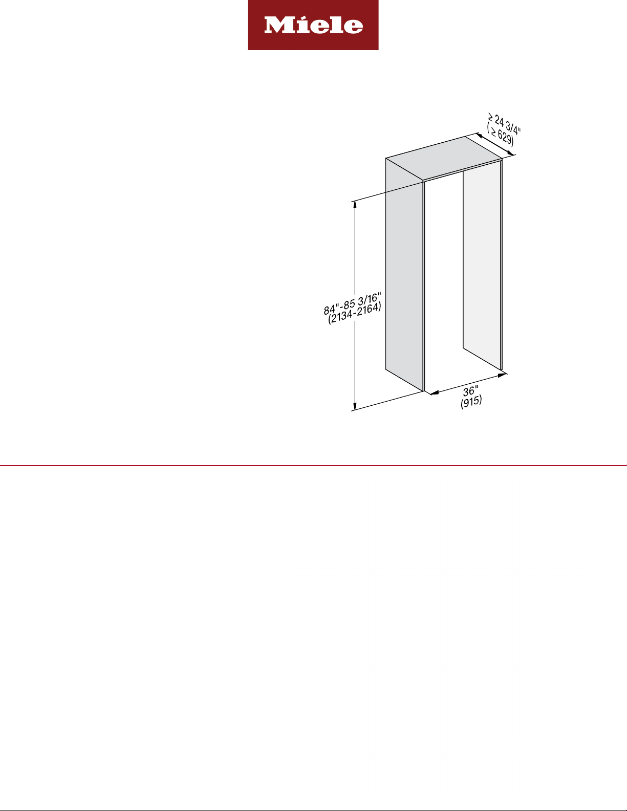
CUTOUT DIMENSIONS
• Niche depth assumes a 3/4” (19 mm) panel, please
adjust according to custom panel thickness
Fully Integrated
36” MasterCool
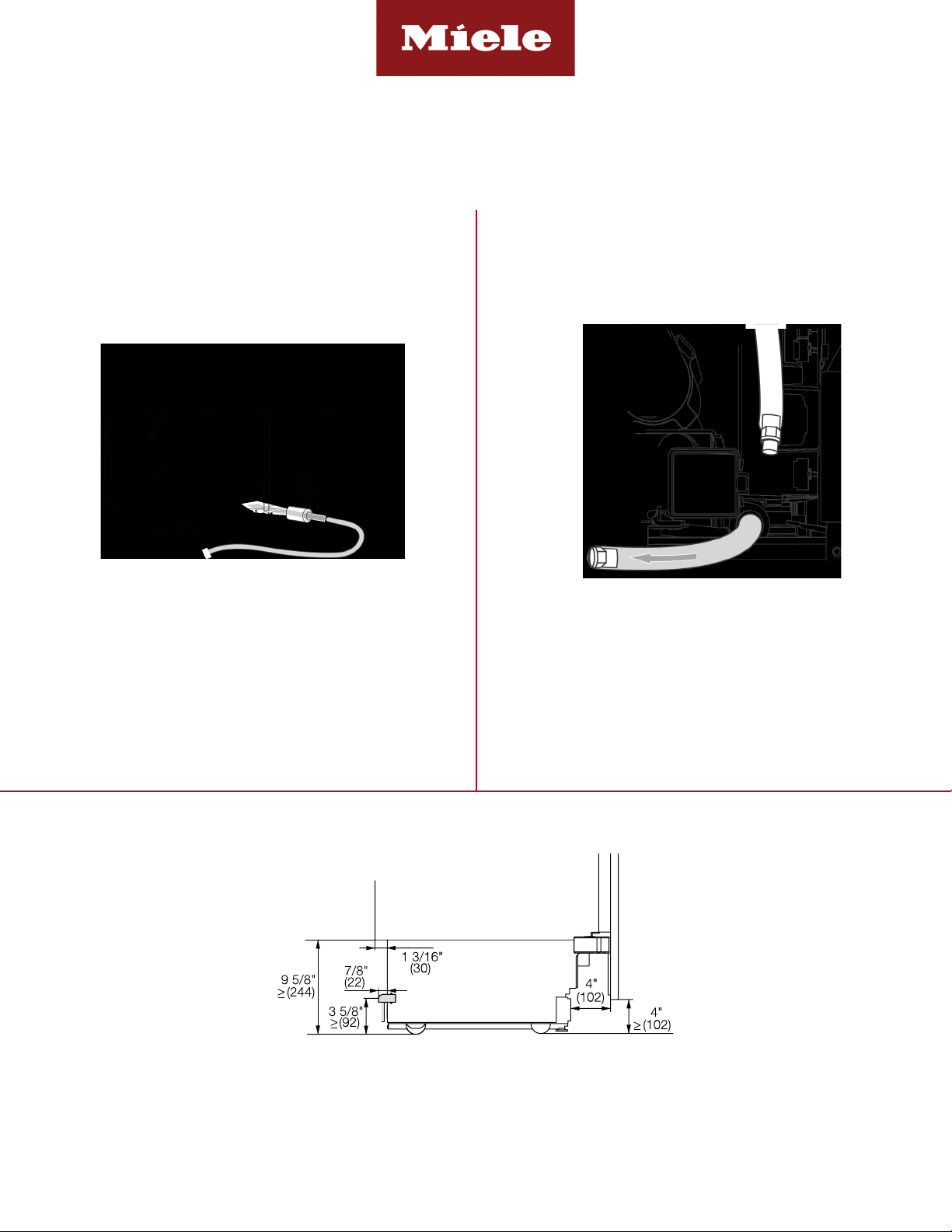
CUTOUT DETAILS
• The electrical connection must not be positioned higher
than 9” (228.6 mm) above the oor.
• The 1/4” (6.4 mm) plumbed water connection should
not be positioned higher than 2” (50.8 mm) above the
oor.
Notes:
In case of an emergency the electrical outlet must be
easily accessible and must not be concealed behind the
appliance.
Page 3 of 12
Page 4
Fully Integrated
36” MasterCool
POWER SUPPLY AND WATER CONNECTION
(Water Connection For F 29x1 Vi & KF 29x1 Vi Only)
Rear View Front View
Electrical - 5 foot (1.52 m) - 120 Volt - 15 Amp
- NEMA 5-15 molded plug
Water line - 1/4” exible water line - not included
Side View
Water connection is located in front of unit.
1/4” compression tting is needed.
Electrical
Connection
Page 4 of 12
Page 5

appearance
These units do not come equipped with a front panel. They are designed to accept a custom door panel supplied by
the
cabinets
Panel
Panel Notes
If
Simply
Fully Integrated
36” MasterCool | K 29x1 Vi & F 29x1 Vi
CUSTOM PANEL INSTALLATIONS
cabinet maker. Miele has a unique panel integration system which allows the panels to align with the surrounding
.
size is determined in the following manner:
Miele
Fully Integrated
Freezer
Panel Height
Width: 29 3/4" in all cases
Thickness: Minimum 3/4" outside frame
Height: Determined using the following calculation:
Panel Height = HOC - TKH
HOC = Total height of cabinet or side panel
TKH = Toe-kick height
HOC
Note: Finish back side of panels to insure
Panel may extend above unit. This is not
considered in height calculation
Minimum 35 3/4” (908 mm)
Minimum 3/4” (19 mm) outside frame
the adjoining cabinets are taller than the height of machine (HOM) - the front panel may be extended accordingly.
maintain the toekick height and extend the panel the needed distance.
Adjoining cabinet
TKH
Extended Panel
Maximum panel weight: 105.8 Pounds
106 Pounds
Machine
Page 5 of 12
Page 6

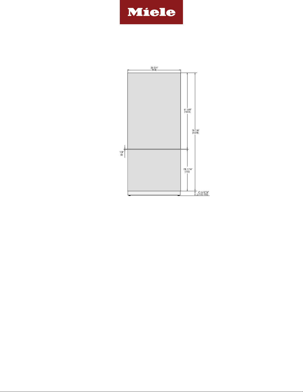
DOOR PANEL DIMENSIONS
KFP 3604 - Door Panel
Available as an accessory
for the following models:
• K 29x1 Vi
• F 29x1 Vi
Fully Integrated
36” MasterCool | K 29x1 Vi & F 29x1 Vi
Page 6 of 12
Page 7

Panel "B" Height
Width: 29 3/4" in all cases
Thickness: Minumum 3/4" outside frame
Standard Upper Panel Height: 53 5/16"
Note: Finish back side of panels to insure appearance
Panel may extend above unit. This is not
considered in height calculation
Upper Maximum panel weight : 103.6 Pounds
Lower Panel Height: Use the following calculation:
Panel Height = HOM - 53 9/16 - TKH
HOM =Total height of machine. Can be adjusted to
match adjoining cabinets - typically 84"
HOM is adjustable between 83 1/2" - 85 3/8"
TKH =Toe-kick height (2" - 8 3/8")
Lower Maximum panel weight:22 Pounds
Upper Panel
TKH
HOM
Panel Height
These units do not come equipped with a front panel. They are designed to accept a custom door panel supplied by
the cabinet maker. Miele has a unique panel integration system which allows the panels to align with the surrounding
cabinets.
Panel size is determined in the following manner:
Lower Panel
Upper Panel Notes
If
Find
These units do not come equipped with a front panel. They are designed to accept a custom door panel supplied by
the
cabinets
Panel
Fully Integrated
36” MasterCool | KF 2901 Vi / KF 2911 Vi
CUSTOM PANEL INSTALLATIONS
cabinet maker. Miele has a unique panel integration system which allows the panels to align with the surrounding
.
size is determined in the following manner:
Width: 29 3/4" in all cases
Thickness: Minumum 3/4" outside frame
Minimum 35 3/4” (756 mm)
Minimum 3/4” (19 mm) outside frame
Standard Upper Panel Height: 53 5/16"
51 3/8” (1304 mm)
Note: Finish back side of panels to insure appearance
Panel may extend above unit. This is not
considered in height calculation
104 lbs
Upper Panel
Panel Height
HOM
Upper Maximum panel weight : 103.6 Pounds
Lower Panel Height: Use the following calculation:
Lower Panel
Panel Height = HOM - 53 9/16 - TKH
HOM - 51 1/2” (1307 mm) - TKH
HOM =Total height of machine. Can be adjusted to
Panel "B" Height
TKH =Toe-kick height (2" - 8 3/8")
TKH
TKH =
Lower Maximum panel weight:22 Pounds
Lower Maximum panel weight: 22 lbs
Total height of machine. Can be adjusted
to match adjoining cabinets - typically 84”
match adjoining cabinets - typically 84"
(2133 mm).
HOM is adjustable between 83 1/2" - 85 3/8"
HOM is adjustable between 84” -85 3/16”
(2134 mm - 2164 mm)
Toe-kick height 2” - 8 3/8” (51 - 212 mm)
the adjoining cabinets are taller than the height of machine (HOM) - the upper panel may be extended accordingly.
the difference between height of the adjoining cabinets and the height of machine (HOM) and add to 53 5/16"
Adjoining cabinet
Extended Panel Example:
Machine
Ajoining cabinet height: 87"
Height of machine: 84"
Difference: 3"
Extended panel height:56 5/16"
87” (2210 mm)
84” (2134 mm)
3” (76 mm)
54 1/2” (1379 mm)
Page 7 of 12
Page 8
DOOR PANEL DIMENSIONS
KFP 3614 - Top Panel
KFP 3624 - Bottom Panel
Available as an accessory
for the following models:
• KF 2901 Vi / KF 2911 Vii
Fully Integrated
36” MasterCool | KF 2901 Vi / KF 2911 Vi
Page 8 of 12
Page 9

Panel "B" Height
Width: 29 3/4" in all cases
Thickness: Minumum 3/4" outside frame
Standard Upper Panel Height: 53 5/16"
Note: Finish back side of panels to insure appearance
Panel may extend above unit. This is not
considered in height calculation
Upper Maximum panel weight : 103.6 Pounds
Lower Panel Height: Use the following calculation:
Panel Height = HOM - 53 9/16 - TKH
HOM =Total height of machine. Can be adjusted to
match adjoining cabinets - typically 84"
HOM is adjustable between 83 1/2" - 85 3/8"
TKH =Toe-kick height (2" - 8 3/8")
Lower Maximum panel weight:22 Pounds
Upper Panel
TKH
HOM
Panel Height
These units do not come equipped with a front panel. They are designed to accept a custom door panel supplied by
the cabinet maker. Miele has a unique panel integration system which allows the panels to align with the surrounding
cabinets.
Panel size is determined in the following manner:
Lower Panel
Upper Panel Notes
If
Find
Fully Integrated
36” MasterCool | KF 2981 Vi
CUSTOM PANEL INSTALLATIONS
Minimum 17 13/16” (452.5 mm)
Minimum 35 3/4” (756 mm)
Minimum 3/4” (19 mm) outside frame
51 3/8” (1304 mm)
104 lbs
HOM - 51 1/2” (1307 mm) - TKH
Total height of machine. Can be adjusted
to match adjoining cabinets - typically 84”
(2133 mm).
HOM is adjustable between 84” -85 3/16”
(2134 mm - 2164 mm)
TKH =
Lower Maximum panel weight: 22 lbs
Toe-kick height 2” - 8 3/8” (51 - 212 mm)
the adjoining cabinets are taller than the height of machine (HOM) - the upper panel may be extended accordingly.
the difference between height of the adjoining cabinets and the height of machine (HOM) and add to 53 5/16"
Adjoining cabinet
Extended Panel Example:
Machine
Ajoining cabinet height: 87"
Height of machine: 84"
Difference: 3"
Extended panel height:56 5/16"
87” (2210 mm)
84” (2134 mm)
3” (76 mm)
54 1/2” (1379 mm)
Page 9 of 12
Page 10
DOOR PANEL DIMENSIONS
KFP 3634 - Top Panels
KFP 3624 - Bottom Panel
Available as an accessory
for the following models:
• KF 2981 Vi
Fully Integrated
36” MasterCool | KF 2981 Vi
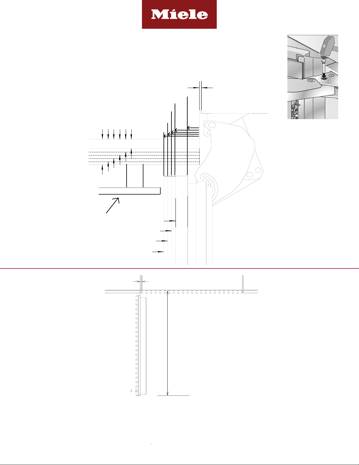
HINGING DETAILS
Page 10 of 12
Page 11

HINGING DETAILS 115° OPENING
0-3/4"
1"
1-1/4"
1-1/2"
0-1/8"
F
ro
nt
Pa
n
el
0-3/4"
1-1/4"
1-1/2"
1-3/4"
1"
Cabinet Front
rooD °511rooD °09
snoitpo ssenkcihTsnoitpo ssenkcihT
0-3/4"
1"
1-1/4"
1-1/2"
0-1/8"
F
ro
nt
Pa
n
el
0-3/4"
1-1/4"
1-1/2"
1-3/4"
1"
Cabinet Front
rooD °511rooD °09
snoitpo ssenkcihTsnoitpo ssenkcihT
Door Swing
Available for the following models:
• K 29x1 Vi
• F 29x1 Vi
• KF 29x1 Vi
1-1/4” (32 mm)
1-1/2” (38 mm)
1-3/4” (44 mm)
0-3/4” (19 mm)
1” (25 mm)
Fully Integrated
36” MasterCool
0-3/4” (19 mm)
2-5/8”
(67mm)
2-5/8”
(67mm)
2-1/3” (59mm)
2-1/3” (59mm)
2-1/24”(52mm)
2-1/24”(52mm)
1-3/8”(35mm)
1-3/8”(35mm)
1-1/6”
1-1/6”
17/24” (18mm)
17/24” (18mm)
(29.6mm)
(29.6mm)
1/4”(6.4mm)
1/4”(6.4mm)
1-3/4”(44.5mm)
1-3/4”(44.5mm)
3”(76.2mm)
3”(76.2mm)
0-1/8” (3 mm)
DOOR SWING AT 115° OPENING
Available for the following models:
• K 29x1 Vi
• F 29x1 Vi
• KF 2901 Vi / KF 2911 Vi
1-1/2” (38 mm)
1” (25 mm)
1-1/4” (32 mm)
11 3/4”
16 7/8"
(298 mm)
MAX
Max
NOTE: Additional space needed depending on
thickness of front panels and handle used
Page 11 of 12
Page 12
HINGING DETAILS 90° OPENING
0-1/8"
Front Panel
1"
1-1/4"
1-1/2"
0-3/4"
0-3/4"
1-1/4"
1-1/2"
1-3/4"
2"
1"
Cabinet Front
0-3/4"
1"
1-1/4"
1-1/2"
F
ro
nt
Pa
n
el
0-3/4"
1-1/4"
1-1/2"
1-3/4"
1"
Cabinet Front
snoitpo ssenkcihTsnoitpo ssenkcihT
0-3/4"
1"
1-1/4"
1-1/2"
0-1/8"
F
ro
nt
Pa
n
el
0-3/4"
1-1/4"
1-1/2"
1-3/4"
1"
Cabinet Front
rooD °511rooD °09
snoitpo ssenkcihTsnoitpo ssenkcihT
Door Swing
14 3/8"
MAX
NOTE: Additional space needed depending on the thickness
of front panels and handle used.
Freezer units cannot be stop pinned at 90°
0-1/8"
Front Panel
1"
1-1/4"
1-1/2"
0-3/4"
0-3/4"
1-1/4"
1-1/2"
1-3/4"
2"
1"
Cabinet Front
0-3/4"
1"
1-1/4"
1-1/2"
0-1/8"
F
ro
nt
Pa
n
el
0-3/4"
1-1/4"
1-1/2"
1-3/4"
1"
Cabinet Front
rooD °511rooD °09
snoitpo ssenkcihTsnoitpo ssenkcihT
Door Swing
Door Swing
16 7/8"
MAX
NOTE: Additional space needed depending on
thickness of front panels and handle used
Available for the following models:
• K 29x1 Vi
• KF 29x1 Vi
2” (51 mm)
1-1/4” (32 mm)
1-3/4” (44 mm)
1-1/2” (38 mm)
0-3/4” (19 mm)
1” (25 mm)
Fully Integrated
36” MasterCool
7/16”
(11 mm)
1-3/16”
(30mm)
1-7/16”
(36.5mm)
1-11/16”
(43mm)
1-15/16”
(49.2mm)
0-1/8” (3 mm)
DOOR SWING AT 90° OPENING
Available for the following models:
• K 29x1 Vi
• KF 2901 Vi / KF 2911 Vi
Handle or object that is
NOT ush with Cabinet
Front.
0-3/4” (19 mm)
1” (25 mm)
1-1/4” (32 mm)
1-1/2” (38 mm)
7/16” (11 mm)
7/16"
38 11/16"
/16” (982 mm)
11
38
When installing hinge side next to an appliance or object that is within range of the door panel,
limit the door opening angle to 90°. This is done by installing the banking pin as illustrated.
Insert the banking pin through the holes and drive in with a hammer.
NOTE: Additional space needed depending on
thickness of front panels and handle used
Specification Sheets TRS 05202019
Page 12 of 12
 Loading...