

Page 1
Fully Integrated
18” MasterCool
F 2411 Vi
F 2461 Vi* / F 2471 Vi
II
Shown: F 2471 Vi merged with K 2801 Vi
note: This information is subject to change
Please
*The following models are not available in Canada : F 2461 Vi
Specification Sheets TRS 04252018
8miele.ca
Page 2
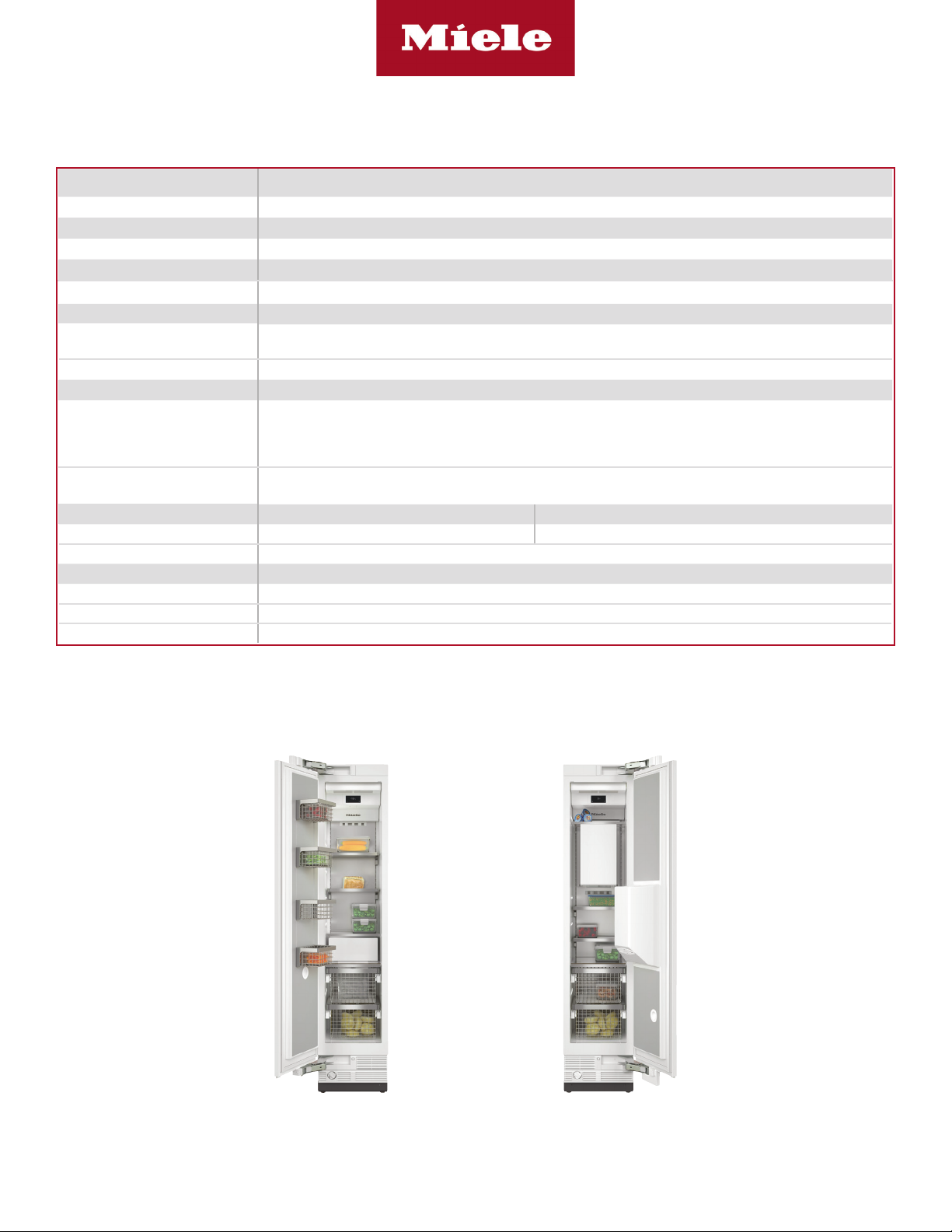
Fully Integrated
18” MasterCool II
SPECIFICATIONS
3
Overall Unit Dimensions 17
Niche
Minimum Cabinet Niche Opening 18” (458 mm) W* x 84” - 85
Interior Volume F 24x1 Vi
Freezer Volume *
Electrical
Electrical Requirements
Power Cord NEMA 5-15 plug, 5 ft (1.52 m)
Plumbing F 24x1 Vi
Connect to a cold water supply only. Do not connect to a low-mineral or a reverse osmosis system. Must be
Water Supply Requirements
connected to a shut-off valve. The water shut-off valve must be accessible after installation. The water pressure
must be between 29 psi (2 bar) and 116 psi (8 bar). If the pressure is higher than 120 psi (8.3 bar), a pressure
reducing valve must be installed.
Water Connection Line
Standard 1/4” O.D flexible water line. The maximum outer diameter of the water pipe (without fittings): 3/8” (10
mm). Water line is not included.
Shipping
Shipping Weight 306 lbs (139 kg) 328 lbs (149 kg)
Shipping Dimensions 21
Support
Call Miele
Miele Website
20/20 Link
Please note the following:
• This specication sheet is for a single built-in unit.
• When combining multiple MasterCool units side-by-side, please refer to the Merging Kit specication sheet.
/4” (451 mm) W x 833/4”- 853/16” (2127 - 2164 mm) H x 24” (610 mm) D [Depth does not include door panel]
3
/16” (2134 - 2164 mm) H x 243/4” (629 mm) D
F 24x1 Vi
110V / 120V, 60Hz, 15 Amps
In the case of side-by-side installations, a separate outlet must be used for each appliance.
F 2411 Vi F 2461 Vi / F 2471 Vi
1
/16” (535 mm) W x 841/4” (1,240 mm) H x 297/8” (759 mm) D
(800) 565-6435
8www.miele.ca
82020technologies.com
*If design calls for a partition less than 6 5/16” (160 mm) the left unit’s cutout will require an additional 1/8” (3 mm) to the width to allow installation of
the Heating Mat/Merge Kit.
F 2411 Vi (Left Hinged)
F 2461 Vi (Right Hinged)
F 2471 Vi (Left Hinged)
Page 2 of 9
Page 3
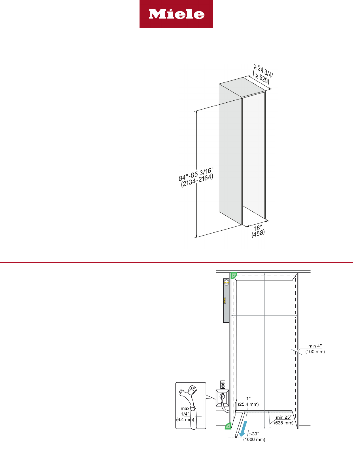
CUTOUT DIMENSIONS
• Niche depth assumes a 3/4” (19 mm) panel, please
adjust according to custom panel thickness
Fully Integrated
18” MasterCool II
CUTOUT DETAILS
• The electrical connection must not be positioned higher
than 9” (228.6 mm) above the oor.
• The 1/4” (6.4 mm) plumbed water connection should
not be positioned higher than 2” (50.8 mm) above the
oor.
Notes:
In case of an emergency the electrical outlet must be
easily accessible and must not be concealed behind the
appliance.
Page 3 of 9
Page 4

Fully Integrated
18” MasterCool II
POWER SUPPLY AND WATER CONNECTION
Rear View Front View
Electrical - 5 foot (1.52 m) - 120 Volt - 15 Amp
- NEMA 5-15 molded plug
Water line - 1/4” exible water line - not included
Side View
Water connection is located in front of unit.
1/4” compression tting is needed.
Electrical
Connection
Page 4 of 9
Page 5

CUSTOM PANEL INSTALLATIONS
Fully Integrated
18” MasterCool II | F 2411 Vi
Minimum 17 3/4” (451 mm)
Minimum 3/4” (19 mm) outside frame
123 Pounds
Page 5 of 9
Page 6

DOOR PANEL DIMENSIONS
KFP1804 - Door Panel
Available as an accessory
for the following models:
• F 2411 Vi
Fully Integrated
18” MasterCool II | F 2411 Vi
Page 6 of 9
Page 7

CUSTOM PANEL INSTALLATIONS
CUSTOM PANEL INSTALLATIONS
Fully Integrated
18” MasterCool II | F 2461 Vi / F 2471 Vi
17 3/4” (451 mm) in all cases
Minimum 3/4” (19 mm) outside frame
143 Pounds
Page 7 of 9
Page 8

DOOR PANEL DIMENSIONS &
DISPENSER CUTOUT
KFP 1844 - Door Panel
Available as an accessory
for the following models:
• F 2461 Vi
• F 2471 Vi
Fully Integrated
18” MasterCool II | F 2461 Vi / F 2471 Vi
Page 8 of 9
Page 9

HINGING DETAILS 115° OPENING
Available for the following models:
• F 24x1 Vi
1-1/4” (32 mm)
1-1/2” (38 mm)
1-3/4” (44 mm)
0-3/4” (19 mm)
1” (25 mm)
Fully Integrated
18” MasterCool II
0-3/4” (19 mm)
2-5/8”
(67mm)
2-5/8”
(67mm)
2-1/3” (59mm)
2-1/3” (59mm)
2-1/24”(52mm)
2-1/24”(52mm)
1-3/8”(35mm)
1-3/8”(35mm)
1-1/6”
1-1/6”
17/24” (18mm)
17/24” (18mm)
(29.6mm)
(29.6mm)
1/4”(6.4mm)
1/4”(6.4mm)
1-3/4”(44.5mm)
1-3/4”(44.5mm)
3”(76.2mm)
3”(76.2mm)
0-1/8” (3 mm)
DOOR SWING AT 115° OPENING
1-1/4” (32 mm)
1-1/2” (38 mm)
11 3/4”
(298 mm)
Max
1” (25 mm)
Specification Sheets TRS 04252018
Page 9 of 9
 Loading...