

Page 1
Gebrauchs- und Montageanweisung
Operating and installation instructions
Dunstabzugshaube
Cooker hoods
DA 119
DA 112
Lesen Sie unbedingt die Gebrauchsanweisung
vor Aufstellung – Installation – Inbetriebnahme.
Dadurch schützen Sie sich und vermeiden
Schäden an Ihrem Gerät.
To avoid the risk of accidents or damage to
the appliance it is essential to read these
operating instructions before
it is installed or used for the first time.
DG
M.-Nr. 05 934 060
Page 2

Inhalt
Ihr Beitrag zum Umweltschutz . . . . . . . . . . . . . . . . . . . . . . . . . . . . . . . . . . . . . . . 3
Sicherheitshinweise und Warnungen . . . . . . . . . . . . . . . . . . . . . . . . . . . . . . . . . 4
Gerätebeschreibung . . . . . . . . . . . . . . . . . . . . . . . . . . . . . . . . . . . . . . . . . . . . . . . 8
Funktionsbeschreibung . . . . . . . . . . . . . . . . . . . . . . . . . . . . . . . . . . . . . . . . . . . 10
Bedienung
Bedienstab. . . . . . . . . . . . . . . . . . . . . . . . . . . . . . . . . . . . . . . . . . . . . . . . . . . . . . . 11
Gebläse einschalten . . . . . . . . . . . . . . . . . . . . . . . . . . . . . . . . . . . . . . . . . . . . 11
Leistungsstufe wählen . . . . . . . . . . . . . . . . . . . . . . . . . . . . . . . . . . . . . . . . . . . 11
Gebläse ausschalten . . . . . . . . . . . . . . . . . . . . . . . . . . . . . . . . . . . . . . . . . . . . 11
Beleuchtung einschalten . . . . . . . . . . . . . . . . . . . . . . . . . . . . . . . . . . . . . . . . . . . 12
Beleuchtung dimmen. . . . . . . . . . . . . . . . . . . . . . . . . . . . . . . . . . . . . . . . . . . . . . . 12
Beleuchtung ausschalten . . . . . . . . . . . . . . . . . . . . . . . . . . . . . . . . . . . . . . . . . . . 12
Nachlauf-Funktion . . . . . . . . . . . . . . . . . . . . . . . . . . . . . . . . . . . . . . . . . . . . . . . . . 13
Betriebsstundenzähler. . . . . . . . . . . . . . . . . . . . . . . . . . . . . . . . . . . . . . . . . . . . . . 13
Betriebsstundenzähler abfragen . . . . . . . . . . . . . . . . . . . . . . . . . . . . . . . . . . . 14
Betriebsstundenzähler einstellen/ändern . . . . . . . . . . . . . . . . . . . . . . . . . . . . . 14
Reinigung und Pflege
Gehäuse . . . . . . . . . . . . . . . . . . . . . . . . . . . . . . . . . . . . . . . . . . . . . . . . . . . . . . . . 17
Allgemein . . . . . . . . . . . . . . . . . . . . . . . . . . . . . . . . . . . . . . . . . . . . . . . . . . . . . 17
Besondere Hinweise für Geräte mit Edelstahlkamin/teleskop . . . . . . . . . . . . . 17
Fettfilter . . . . . . . . . . . . . . . . . . . . . . . . . . . . . . . . . . . . . . . . . . . . . . . . . . . . . . . . . 18
Geruchsfilter einsetzen / austauschen . . . . . . . . . . . . . . . . . . . . . . . . . . . . . . . . . 19
Halogen-Leuchtmittel wechseln . . . . . . . . . . . . . . . . . . . . . . . . . . . . . . . . . . . . . . 21
Kundendienst . . . . . . . . . . . . . . . . . . . . . . . . . . . . . . . . . . . . . . . . . . . . . . . . . . . . 22
Gerätemaße . . . . . . . . . . . . . . . . . . . . . . . . . . . . . . . . . . . . . . . . . . . . . . . . . . . . . 23
Montage
Montagematerial . . . . . . . . . . . . . . . . . . . . . . . . . . . . . . . . . . . . . . . . . . . . . . . . . . 24
Montageanweisung . . . . . . . . . . . . . . . . . . . . . . . . . . . . . . . . . . . . . . . . . . . . . . . . 26
Demontage . . . . . . . . . . . . . . . . . . . . . . . . . . . . . . . . . . . . . . . . . . . . . . . . . . . . . . 26
Abluftleitung. . . . . . . . . . . . . . . . . . . . . . . . . . . . . . . . . . . . . . . . . . . . . . . . . . . . . 27
Kondenswassersperre. . . . . . . . . . . . . . . . . . . . . . . . . . . . . . . . . . . . . . . . . . . . . . 28
Elektroanschluss . . . . . . . . . . . . . . . . . . . . . . . . . . . . . . . . . . . . . . . . . . . . . . . . . 29
Technische Daten. . . . . . . . . . . . . . . . . . . . . . . . . . . . . . . . . . . . . . . . . . . . . . . . . 30
G . . . . . . . . . . . . . . . . . . . . . . . . . . . . . . . . . . . . . . . . . . . . . . . . . . . . . . . . . . . . 32
2
Page 3

Ihr Beitrag zum Umweltschutz
Entsorgung der Transportver
-
packung
Die Verpackung schützt das Gerät vor
Transportschäden. Die Verpackungs
materialien sind nach umweltverträgli
chen und entsorgungstechnischen Ge
sichtspunkten ausgewählt und deshalb
recycelbar.
Das Rückführen der Verpackung in den
Materialkreislauf spart Rohstoffe und
verringert das Abfallaufkommen. Ihr
Fachhändler nimmt die Verpackung zu
rück.
-
-
Entsorgung des Altgerätes
Altgeräte enthalten vielfach noch wert
volle Materialien. Geben Sie deshalb Ihr
Altgerät entweder über Ihren Händler
oder über das öffentliche Sammelsys
tem in den Materialkreislauf zurück.
Bitte sorgen Sie dafür, dass das Altge
rät bis zum Abtransport kindersicher
aufbewahrt wird. Hierüber informiert Sie
die Gebrauchsanweisung unter der Ru
brik “Sicherheitshinweise und Warnun
gen”.
-
-
-
-
-
-
3
Page 4
Sicherheitshinweise und Warnungen
Technische Sicherheit
Dieses Gerät entspricht den vorge
schriebenen Sicherheitsbestimmun
gen. Ein unsachgemäßer Gebrauch
kann jedoch zu Schäden an Perso
nen und Sachen führen.
Lesen Sie vor dem ersten Benutzen
des Gerätes aufmerksam die Ge
brauchsanweisung. Sie gibt wichtige
Hinweise für die Sicherheit, die Mon
tage, den Gebrauch und die War
tung des Gerätes. Dadurch schüt
zen Sie sich und verhindern Schä
den am Gerät.
Bewahren Sie diese Gebrauchsanweisung auf, und geben Sie sie
einem eventuellen Nachbesitzer weiter.
Bestimmungsgemäße Verwendung der Dunstabzugshaube
Das Gerät ist für die Verwendung
im Haushalt bestimmt.
Der Hersteller haftet nicht für Schäden,
die durch bestimmungswidrigen Ge
brauch oder falsche Bedienung verur
sacht werden.
Diese Geräteeinheit darf nur in Ver
bindung mit dem entsprechenden
Holzumbau von Miele montiert und be
trieben werden.
-
-
-
-
-
-
-
-
-
-
-
-
Vergleichen Sie vor dem Anschlie
ßen der Dunstabzugshaube unbe
dingt die Anschlussdaten (Spannung
und Frequenz) auf dem Typenschild mit
denen des Elektronetzes (siehe "Elek
troanschluss").
Diese Daten müssen übereinstimmen,
damit keine Schäden am Gerät auftre
ten. Im Zweifelsfall fragen Sie Ihren
Elektroinstallateur.
Die elektrische Sicherheit der
Dunstabzugshaube ist nur dann
gewährleistet, wenn sie an ein vor
schriftsmäßig installiertes Schutzleitersystem angeschlossen wird. Es ist sehr
wichtig, dass diese grundlegende Sicherheitsvoraussetzung vorhanden ist.
Im Zweifelsfall die Hausinstallation
durch eine Fachkraft überprüfen lassen. Der Hersteller kann nicht für Schäden verantwortlich gemacht werden,
die durch einen fehlenden oder unterbrochenen Schutzleiter verursacht werden (z. B. elektrischer Schlag).
Durch unsachgemäße Installations-
und Wartungsarbeiten oder Repa
raturen können erhebliche Gefahren für
den Benutzer entstehen. Lassen Sie In
stallations- und Wartungsarbeiten sowie
Reparaturen an Elektrogeräten nur von
qualifizierten Fachleuten durchführen.
Der Einbau und die Montage die
ses Gerätes an nichtstationären
Aufstellungsorten (z.B. Schiffe) dürfen
nur von Fachbetrieben/Fachleuten
durchgeführt werden, wenn sie die Vor
aussetzungen für den sicherheitsge
rechten Gebrauch dieses Gerätes si
cherstellen.
-
-
-
-
-
-
-
-
-
-
-
4
Page 5

Sicherheitshinweise und Warnungen
Die Dunstabzugshaube ist nur
dann elektrisch vom Netz getrennt,
wenn eine der folgenden Bedingungen
erfüllt ist:
die Netzanschlussleitung vom Elek
–
tronetz getrennt ist.
Ziehen Sie nicht an der Netzan
schlussleitung, sondern am Netzste
cker, um das Gerät vom Netz zu tren
nen.
die Sicherung der Hausinstallation
–
ausgeschaltet ist.
die Schraubsicherung der Hausin
–
stallation ganz herausgeschraubt ist.
Der Anschluss des Gerätes an das
Elektronetz darf nicht über ein Verlängerungskabel erfolgen.
Verlängerungskabel gewähren nicht die
nötige Sicherheit des Gerätes (z. B.
Überhitzungsgefahr).
-
-
-
Gebrauch
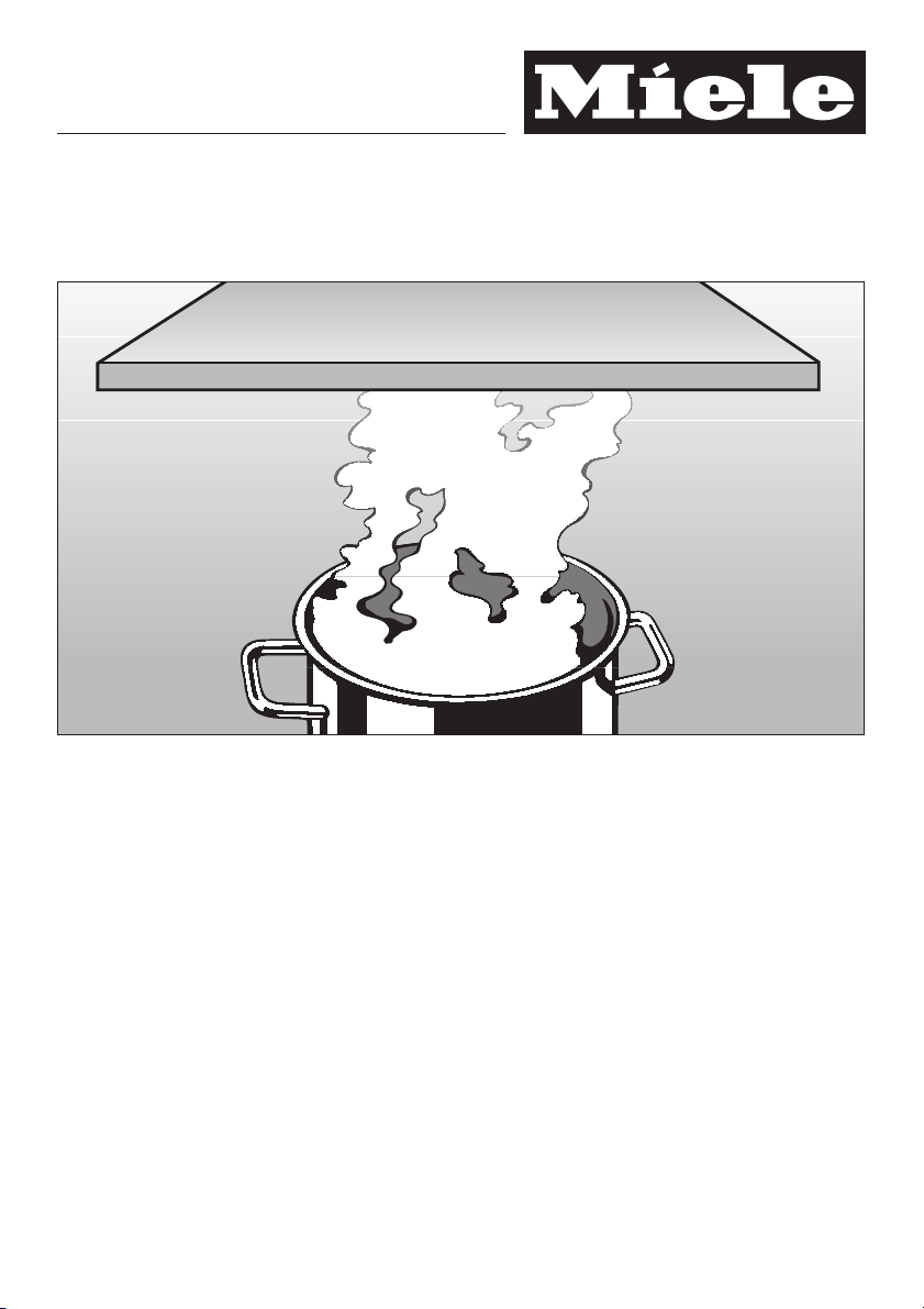
Arbeiten Sie nie mit offener Flam-
me unter der Dunstabzugshaube;
so ist z. B. das Flambieren und das
Grillen mit offener Flamme verboten.
Die eingeschaltete Dunstabzugshaube
zieht die Flammen in den Filter. Durch
aufgesaugtes Küchenfett besteht
Brandgefahr!
Beim Benutzen der Dunstabzugs
haube über Gas-Kochstellen muss
unbedingt darauf geachtet werden,
dass die benutzte Brennstelle durch
das Kochgeschirr bedeckt wird.
Die Dunstabzugshaube kann durch die
Hitzeeinwirkung der Flammen beschä
digt werden.
-
-
Schalten Sie die Dunstabzugshau
be immer ein, wenn eine Kochstel
le benutzt wird.
Bei nicht eingeschalteter Dunstabzugs
haube kann sich Kondenswasser an
sammeln. Hierdurch können Korro
sionsschäden am Gerät entstehen.
-
-
Beaufsichtigen Sie Töpfe, Pfannen
und Fritiergeräte, wenn Sie mit
Ölen und Fetten arbeiten. Auch das
Grillen über Elektro-Grillgeräten muss
unter ständiger Aufsicht erfolgen.
Überhitzte Öle und Fette können sich
selbst entzünden und dadurch die
Dunstabzugshaube in Brand setzen.
Benutzen Sie die Dunstabzugshau-
be nie ohne Fettfilter.
Dadurch vermeiden Sie Fett- und
Schmutzablagerungen im Gerät. Diese
beeinträchtigen die Funktion.
Reinigen oder wechseln Sie die Fil-
ter in regelmäßigen Abständen.
Ein überfetteter Filter bedeutet Brandgefahr! (siehe "Reinigung und Pflege")
Verwenden Sie zum Reinigen der
Dunstabzugshaube auf keinen Fall
ein Dampf-Reinigungsgerät.
Der Dampf kann an spannungsführen
de Teile der Dunstabzugshaube gelan
gen und einen Kurzschluss verursa
chen.
-
-
-
-
-
-
-
-
5
Page 6
Sicherheitshinweise und Warnungen
Montage
Zwischen Kochstelle und der
Dunstabzugshaube muss folgen
der Sicherheitsabstand mindestens ein
gehalten werden:
– 45 cm über einer Elektro-Kochstelle,
– 65 cm über einer Gas-Kochstelle,
– 65 cm über einem Elektro-Grill aus
unserem Programm
Für andere Kochgeräte ist der in der
zugehörigen Montage- und Gebrauchs
anweisung angegebene Sicherheitsab
stand einzuhalten.
Sollten verschiedene Kochgeräte unter
der Dunstabzugshaube betrieben werden, für die unterschiedliche Sicherheitsabstände gelten, ist der größte angegebene Sicherheitsabstand zu wählen.
Über Feuerungsstätten mit festen
Brennstoffen darf die Dunstabzugshaube nicht montiert werden.
-
-
-
-
Zum Verlegen der Abluftleitung
dürfen nur Rohre oder Schläuche
aus nichtbrennbarem Material verwen
det werden. Diese sind im Fachhandel
oder beim Kundendienst erhältlich.
Die Abluft darf weder in einen in
Betrieb befindlichen Rauch- oder
Abgaskamin noch in einen Schacht ge
führt werden, welcher der Entlüftung
von Aufstellungsräumen mit Feuerstät
ten dient.
Soll die Abluft in einen außer Be
trieb befindlichen Rauch- oder Ab
gaskamin geführt werden, so sind die
behördlichen Vorschriften zu beachten.
6
-
-
-
-
-
Page 7
Sicherheitshinweise und Warnungen
Bei gleichzeitigem Betrieb einer
Dunstabzugshaube und einer
raumluftabhängigen Feuerstätte (wie
gas-, öl- oder kohlebetriebene Heizge
räte, Durchlauferhitzer, Warmwasserbe
reiter, Gaskochmulden, Gasbacköfen)
ist Vorsicht geboten, da beim Absau
gen der Luft durch die Dunstabzugs
haube dem Aufstellraum und benach
barten Räumen die Luft entnommen
wird, die die Feuerstätte zum Verbren
nen benötigt.
Außerdem können durch den Sog der
Dunstabzugshaube Abgas-Rückströ
mungen aus dem Kamin oder Abzugs
schacht entstehen; schornsteingebundene Feuerstätten werden beeinträchtigt.
Ein gefahrloser Betrieb ist möglich,
wenn bei gleichzeitigem Betrieb von
Dunstabzugshaube und raumluftabhängiger Feuerstätte ein Unterdruck von
höchstens 4 Pa (0,04 mbar) erreicht
und damit ein Rücksaugen der Feuerstättenabgase vermieden wird.
Dies kann erreicht werden, wenn durch
nicht verschließbare Öffnungen, z. B. in
Türen, in Fenster, durch Zuluft- / Abluft
mauerkasten oder andere technische
Maßnahmen, wie gegenseitige Verrie
gelung o. ä., die zur Verbrennung be
nötigte Luft nachströmen kann.
-
-
-
-
-
-
-
-
-
Entsorgung des Altgerätes
Ziehen Sie bei ausgedienten Gerä
ten den Netzstecker aus der Steck
dose, und machen Sie Netzanschluss
leitung sowie Stecker unbrauchbar.
Sie verhindern damit, dass ein Missbrauch mit der Dunstabzugshaube ge
trieben wird.
Der Hersteller kann nicht für Schä
den verantwortlich gemacht werden,
die infolge von Nichtbeachtung der
Sicherheitshinweise und Warnungen
verursacht werden.
-
-
-
-
-
-
Anmerkung: Bei der Beurteilung muss
immer der gesamte Lüftungsverbund
der Wohnung beachtet werden. Fragen
Sie im Zweifelsfall den zuständigen
Schornsteinfegermeister.
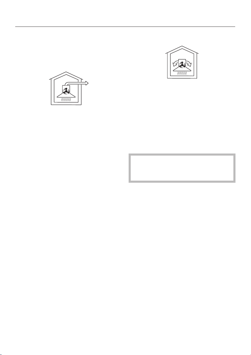
Wird die Dunstabzugshaube im
Umluftbetrieb eingesetzt, ist dies ohne
Einschränkungen möglich.
7
Page 8
Gerätebeschreibung
8
Page 9

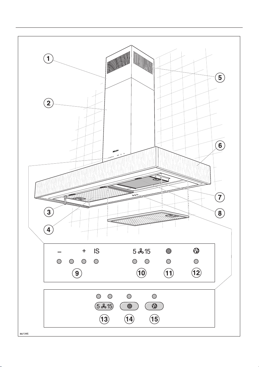
Gerätebeschreibung
a Teleskop
b Kamin
c Bedienstab
Die Hauptfunktionen für Gebläse und
Kochstellenbeleuchtung können Sie
über den Bedienstab schalten.
d Fettfilter
e Umluftaustritt
(nur bei Umluftbetrieb)
f Wrasenschirm
g Geruchsfilter
(Sonderzubehör für Umluftbetrieb)
h Kochstellenbeleuchtung
i Gebläsestufenanzeige
Die Kontrolllampen zeigen die eingestellte Leistungsstufe des Gebläses
und dienen der Anzeige der Betriebsstundenzähler.
j Nachlaufanzeige
Die Lampen zeigen die eingestellte
Nachlaufzeit an.
k Fettfilter-Kontrolllampe
Die Lampe leuchtet, wenn die Fettfil
ter gereinigt werden müssen.
l Geruchsfilter-Kontrolllampe
Die Lampe leuchtet, wenn die im
Umluftbetrieb eingesetzten Geruchs
filter ausgetauscht werden müssen.
n Fettfilter-Taste
Mit der Taste kann
jederzeit nach Reinigung der Fettfil
–
ter der Betriebsstundenzähler zu
rückgesetzt werden (siehe "Reini
gung und Pflege").
die abgelaufene Zeit des Betriebs
–
stundenzählers angezeigt werden
(siehe Kapitel "Bedienung / Betriebs
stundenzähler").
die Stundenzahl für den Betriebs
–
stundenzähler verändert werden
(siehe Kapitel "Bedienung / Betriebs
stundenzähler ändern").
o Geruchsfilter-Taste
Mit der Taste kann
– jederzeit nach Wechsel der Geruchs-
filter der Betriebsstundenzähler zurückgesetzt werden (siehe "Reinigung und Pflege").
– die abgelaufene Zeit des Betriebs-
stundenzählers angezeigt werden
(siehe Kapitel "Bedienung / Betriebs
-
stundenzähler").
–
die Stundenzahl für den Betriebs
stundenzähler verändert werden
(siehe Kapitel "Bedienung / Betriebs
-
stundenzähler ändern").
-
-
-
-
-
-
-
-
-
-
m Taste für die Nachlauf-Funktion
Hiermit können Sie die Nach
lauf-Funktion aktivieren. Das Gebläse
wird automatisch nach wahlweise 5
oder 15 Minuten abgeschaltet.
-
9
Page 10
Funktionsbeschreibung
Die Dunstabzugshaube arbeitet
...im Abluftbetrieb:
Die angesaugte Luft wird durch einen
Fettfilter (DA 119) bzw. zwei Fettfilter
(DA 112) gereinigt und nach außen
geleitet.
Für den Fall, dass Ihr Abluftsystem
nicht über eine Rückstauklappe verfügt, liegt der Dunstabzugshaube eine
Rückstauklappe bei.
Eine Rückstauklappe im Abluftsystem
sorgt dafür, dass bei ausgeschalteter
Dunstabzugshaube kein ungewollter
Luftaustausch zwischen Raum- und Außenluft stattfindet.
...im Umluftbetrieb:
Die angesaugte Luft wird durch die
Fettfilter und zusätzlich durch einen
Geruchsfilter (DA 119) bzw. zwei Ge
ruchsfilter (DA 112) gereinigt. Die Luft
wird durch Öffnungen im Teleskop der
Dunstabzugshaube in die Küche zu
rückgeführt.
Die Geruchsfilter sind als Zubehör erhältlich (siehe "Technische Daten").
Bei Umluftbetrieb bitte darauf achten,
dass die Geruchsfilter eingesetzt
sind, siehe "Reinigung und Pflege".
-
-
Sie ist bei ausgeschalteter Dunstab
zugshaube geschlossen.
Nach dem Einschalten des Gerätes öff
net sich die Rückstauklappe, so dass
die Abluft ungehindert nach außen
transportiert werden kann.
10
-
-
Page 11
Bedienung
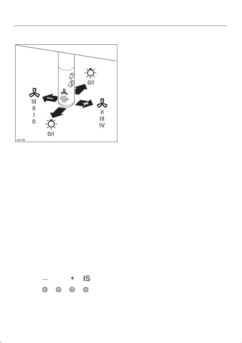
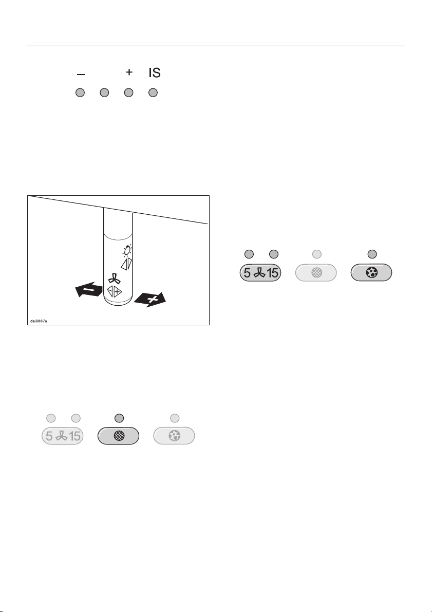
Bedienstab
Die Hauptfunktionen für Gebläse und
Kochstellenbeleuchtung können Sie
über den Bedienstab schalten.
Gebläse einschalten
^ Drücken Sie den Bedienstab einmal
nach rechts.
Dem normalen Kochen dienen je nach
Intensität der Kochdünste die Leis
tungsstufen "I" bis "III" (grüne Kontroll
lampen).
Für vorübergehende starke Wrasenund Geruchsentwicklung, z.B. beim An
braten, steht Ihnen die Intensivstufe zur
Verfügung (gelbe Kontrolllampe).
Gebläse ausschalten
Drücken sie den Bedienstab mehr
^
mals nach links, bis sich das Geblä
se ausschaltet und keine Kontrollam
pe der Gebläsestufenanzeige mehr
leuchtet.
oder
^ Drücken Sie den Bedienstab nach
links und halten Sie ihn gedrückt.
Die Kontrolllampen der Gebläsestu-
fenanzeige erlöschen.
-
-
-
-
-
-
Das Gebläse schaltet auf Stufe "II".
Die zweite Kontrolllampe der Gebläse
stufenanzeige leuchtet.
Leistungsstufe wählen
^
Durch mehrmaliges Drücken des Be
dienstabes nach rechts wählen Sie
eine höhere Leistungsstufe, nach
links eine niedrigere Leistungsstufe.
Die entsprechende Kontrolllampe der
Gebläsestufenanzeige leuchtet.
-
-
11
Page 12
Bedienung
Beleuchtung einschalten
Die Kochstellenbeleuchtung können Sie
unabhängig vom Gebläse ein- oder
ausschalten.
^ Drücken Sie zum Einschalten den
Bedienstab einmal kurz nach hinten
oder nach vorne.
Die Beleuchtung schaltet auf maximale
Helligkeit.
Wenn der Bedienstab gedrückt ge
^
halten wird, erfolgt ein ständiger
Wechsel hell/dunkel.
-
Beleuchtung ausschalten
Zum Ausschalten den Bediensab er
^
neut einmal kurz nach hinten oder
vorne drücken.
Sicherheitsausschaltung
Wird die eingeschaltete Dunstabzugs
haube 10 Stunden lang nicht bedient,
schaltet sich das Gebläse automatisch
ab. Die Beleuchtung bleibt eingeschaltet.
^ Zum Wiedereinschalten des Geblä-
ses den Bedienstab einmal nach
rechts drücken.
-
-
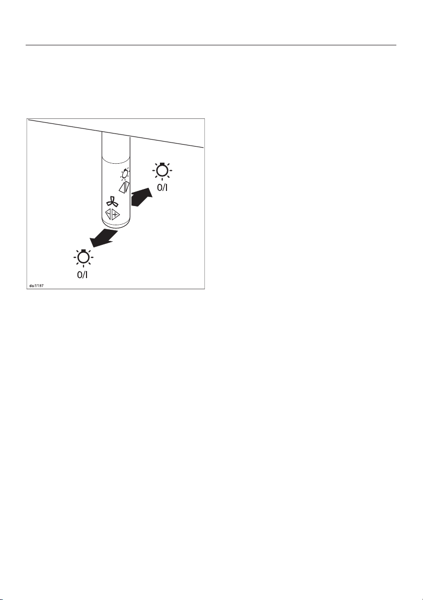
Beleuchtung dimmen
Sie haben die Möglichkeit, die Hellig
keit des Lichtes stufenlos zu variieren.
^
Halten Sie dazu bei eingeschaltetem
Licht den Bedienstab nach hinten
oder vorne gedrückt.
Die Helligkeit wird stufenlos herunter
geregelt, bis Sie den Bedienstab los
lassen.
^
Wenn Sie den Bedienstab erneut ge
drückt halten, wird die Helligkeit wie
der hinaufgeregelt, bis Sie den Be
dienstab loslassen.
12
-
-
-
-
-
-
Page 13
Bedienung
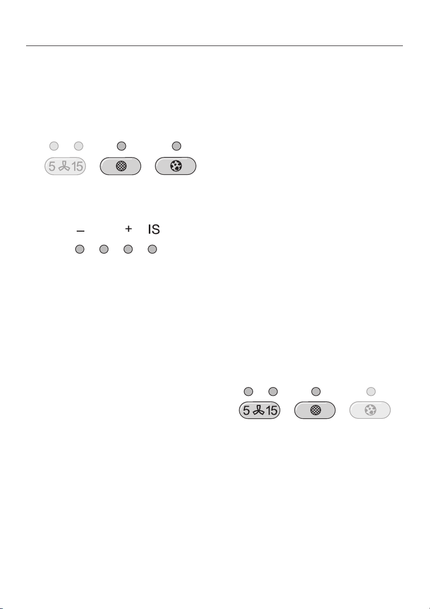
Nachlauf-Funktion
Es ist sowohl bei Abluft- als auch bei
Umluftbetrieb empfehlenswert, das Ge
bläse nach dem Kochen noch einige
Minuten weiterlaufen zu lassen.
Damit wird die Küchenluft von verblie
benen Wrasen und Gerüchen gereinigt.
Die Nachlauf-Funktion ermöglicht es,
dass sich das Gebläse nach einer vor
gewählten Zeit automatisch abschaltet.
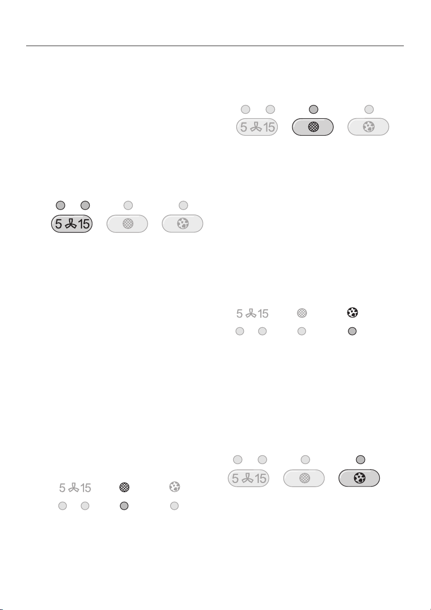
^ Drücken Sie nach dem Kochen bei
eingeschaltetem Gebläse die Taste
für die Nachlauf-Funktion –
– 1-mal: Das Gebläse schaltet sich
nach 5 Minuten aus (linke Kontrolllampe).
– 2-mal: Das Gebläse schaltet sich
nach 15 Minuten aus (rechte Kontrolllampe).
Zum Ausschalten der Nachlauf-Funktion
die Taste erneut drücken. Das Gebläse
läuft weiter.
-
Betriebsstundenzähler
Die Zeit, die die Dunstabzugshaube in
Betrieb ist, wird im Gerät gespeichert.
Der Betriebsstundenzähler muss an
schließend wieder zurückgesetzt wer
den.
-
Halten Sie dazu die Fettfilter-Taste ca.
^
-
3 Sekunden gedrückt.
Die Fettfilter-Kontrolllampe erlischt.
Bei Umluftbetrieb:
Den Betriebsstundenzähler für die Ge-
ruchsfilter können Sie nach Ihren Bedürfnissen einstellen (siehe "Betriebsstunden Geruchsfilter einstellen/ ändern").
Nach der vorgewählten Betriebszeit
leuchtet die Kontrolllampe der Ge
ruchsfilter-Taste. Die Geruchsfilter
müssen dann gewechselt werden.
Der Betriebsstundenzähler muss an
schließend wieder zurückgesetzt wer
den.
-
-
-
-
-
Nach einer Betriebszeit von 30 Stunden
leuchtet die Fettfilter-Kontrolllampe. Die
Fettfilter müssen dann gereinigt werden.
^
Halten Sie dazu die Geruchsfilter-Tas
te ca. 3 Sekunden gedrückt.
Die Geruchsfilter-Kontrolllampe erlischt.
13
-
Page 14
Bedienung
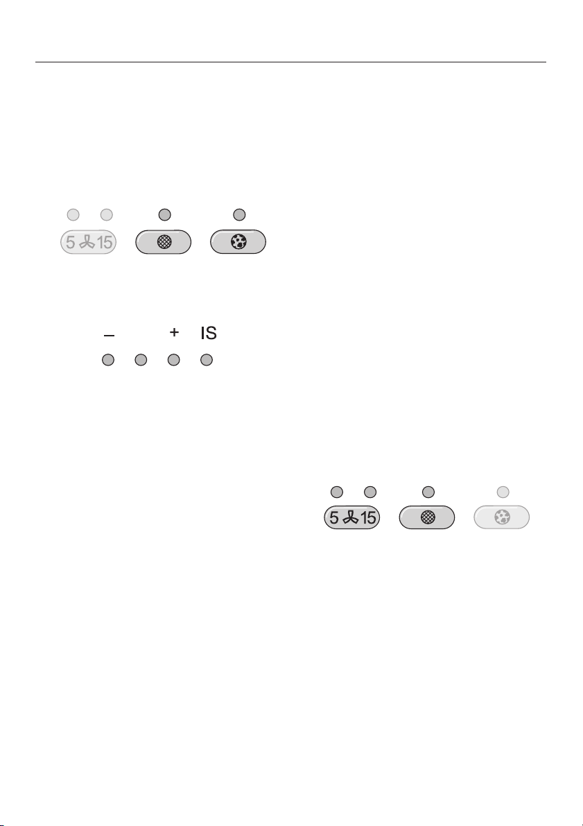
Betriebsstundenzähler abfragen
Vor Ablauf der Betriebszeit können Sie
sich anzeigen lassen, wieviel Prozent
der Zeit bereits abgelaufen ist.
Schalten Sie das Gebläse mit dem
^
Bedienstab ein.
Drücken Sie die Fettfilter-Taste bzw.
^
die Geruchsfilter-Taste.
Eine oder mehrere Kontrolllampen der
Gebläsestufenanzeige blinken.
Die Anzahl der blinkenden Kontrolllampen gibt die abgelaufene Betriebszeit
in Prozent an.
Betriebsstundenzähler
einstellen/ändern
Sie können die Betriebsstundenzähler
Ihren Kochgewohnheiten anpassen.
Wählen Sie kurze Betriebszeiten,
–
wenn Sie viel braten und fritieren.
Wenn Sie sehr fettarm kochen, kön
–
nen Sie lange Betriebszeiten wählen.
Wenn Sie nur gelegentlich kochen,
–
sind kurze Betriebszeiten sinnvoll.
Angesammeltes Fett verhärtet sich
über einen langen Zeitraum und er
schwert die Reinigung der Fettfilter.
Betriebsstunden Fettfilter ändern
Der Betriebsstundenzähler für den Fettfilter ist auf 30 Stunden eingestellt. Sie
können die Zeit verändern, wählbar
sind 20, 30, 40 oder 50 Stunden.
^ Schalten Sie das Gebläse mit dem
Bedienstab aus.
-
-
1 Kontrolllampe = 25 %
2 Kontrolllampen = 50 %
3 Kontrolllampen = 75 %
4 Kontrolllampen = 100 %
Beim Ausschalten der Dunstabzugs
haube oder bei Stromausfall bleiben
die abgelaufenen Betriebsstunden ge
speichert.
14
-
^
Drücken Sie gleichzeitig die Taste für
die Nachlauf-Funktion und die Fettfil
-
ter-Taste.
Die Fettfilter-Kontrolllampe und eine
Kontrolllampe der Gebläsestufenanzei
ge blinken.
-
-
Page 15
Bedienung
Betriebsstunden Geruchsfilter
einstellen/ändern
(bei Umluftbetrieb)
Die Kontrolllampen der Gebläsestufen
anzeige zeigen die eingestellte Zeit an:
1. Lampe von links = 20 Stunden
2. Lampe von links = 30 Stunden
3. Lampe von links = 40 Stunden
4. Lampe von links = 50 Stunden
^ Wählen Sie mit dem Bedienstab die
gewünschte Zeit.
Drücken Sie nach links für eine kürzere Betriebszeit, nach rechts für
eine längere Betriebszeit.
Die Geruchsfilter werden für den Um
luftbetrieb benötigt.
Im Betriebsstundenzähler für die Ge
ruchsfilter ist keine Zeit voreingestellt.
Stellen Sie für den Umluftbetrieb die
Betriebszeit nach Ihren Bedürfnissen
ein:
Schalten Sie das Gebläse mit dem
^
Bedienstab aus.
^ Drücken Sie gleichzeitig die Taste für
die Nachlauf-Funktion und die Geruchsfilter-Taste.
Die Geruchsfilter-Kontrolllampe und
eine Kontrolllampe der Gebläsestufenanzeige blinken.
-
-
^
Bestätigen Sie den Vorgang mit der
Fettfilter-Taste.
Erfolgt die Bestätigung nicht innerhalb
von 4 Minuten nach dem Einstellen,
übernimmt das Gerät automatisch die
"alten" Daten.
15
Page 16
Bedienung
Die Kontrolllampen der Gebläsestufen
anzeige zeigen die eingestellte Zeit an:
1. Lampe von links = 120 Stunden
2. Lampe von links = 180 Stunden
3. Lampe von links = 240 Stunden
4. Lampe von links = unendlich
^ Wählen Sie mit dem Bedienstab die
gewünschte Zeit.
Drücken Sie nach links für eine kürzere Betriebszeit, nach rechts für
eine längere Betriebszeit.
-
^
Bestätigen Sie den Vorgang mit der
Geruchsfilter-Taste.
Erfolgt die Bestätigung nicht innerhalb
von 4 Minuten nach dem Einstellen,
übernimmt das Gerät automatisch die
"alten" Daten.
16
Page 17
Vor jeder Wartung und Pflege die
Dunstabzugshaube vom Elektronetz
trennen, dazu
– den Netzstecker des Gerätes zie
hen oder
– die Sicherung der Hausinstallation
ausschalten oder
– die Schraubsicherung der Hausin
stallation ganz herausschrauben.
Gehäuse
Allgemein
Die Oberflächen und Bedienelemente sind empfindlich gegen Kratzer
und Schnitte. Beachten Sie daher
die folgenden Reinigungshinweise.
^ Reinigen Sie alle Oberflächen und
Bedienelemente nur mit einem
Schwammtuch, Spülmittel und war
mem Wasser.
^
Trocknen Sie die Oberflächen an
schließend mit einem weichen Tuch.
Im Bereich der Bedienelemente
nicht zu feucht reinigen, um ein Ein
dringen von Nässe in die Elektronik
zu vermeiden.
Reinigung und Pflege
Vermeiden Sie
soda-, säure-, chlorid- oder lösungs
–
mittelhaltige Reinigungsmittel,
-
-
-
-
-
scheuernde Reinigungsmittel, wie
–
z.B. Scheuerpulver, Scheuermilch,
scheuernde Schwämme, wie z. B.
Topfschwämme oder gebrauchte
Schwämme, die noch Reste von
Scheuermitteln enthalten.
Besondere Hinweise für Geräte mit
Edelstahlkamin/teleskop
Über die allgemeinen Hinweise hinaus
eignet sich zur Reinigung der Edelstahlflächen ein nicht scheuerndes
Edelstahl-Reinigungsmittel.
Um ein schnelles Wiederverschmutzen
zu verhindern, ist die Behandlung mit
Edelstahl-Pflegemittel empfehlenswert
(erhältlich über den Kundendienst).
Tragen Sie das Mittel mit einem weichen Tuch flächig und sparsam auf.
Besondere Hinweise für Bedientasten
Die Bedientasten können sich ver
färben oder verändern, wenn Ver
schmutzungen länger einwirken.
Entfernen Sie Verschmutzungen da
her sofort.
Beachten Sie zur Reinigung die allge
meinen Hinweise in diesem Kapitel.
-
-
-
-
-
Zur Reinigung der Bedientasten kei
ne Edelstahl-Reinigungsmittel ver
wenden.
-
-
17
Page 18
Reinigung und Pflege
Fettfilter
Die wiederverwendbaren Metall-Fettfil
ter im Gerät nehmen die festen
Bestandteile des Küchendunstes auf
(Fett, Staub usw.) und verhindern so ein
Verschmutzen der Dunstabzugshaube.
Die DA 119 verfügt über einen, die
DA 112 über zwei Fettfilter.
Reinigen Sie die Fettfilter spätestens
dann, wenn die Fettfilter-Kontrolllampe
leuchtet.
Empfehlenswert ist es, die Fettfilter alle
3–4 Wochen zu reinigen, da somit ein
Festsetzen des Fettes vermieden wird.
Ein überfetteter Filter bedeutet
Brandgefahr!
-
Drücken Sie die Verriegelung des
^
Fettfilters in Richtung Filtermitte und
nehmen Sie ihn nach unten heraus
Achten Sie darauf, dass der Fettfilter
nicht auf die Kochstelle fällt.
^ Reinigen Sie die Fettfilter –
– von Hand: Mit einer Spülbürste in
warmem Wasser, dem ein Handspülmittel zugegeben wird.
– im Geschirrspüler: Die Fettfilter
senkrecht in den Unterkorb stellen
und im 65°-Programm spülen.
18
Bei der Reinigung der Fettfilter im
Geschirrspüler kann es je nach ver
wendetem Reiniger zu bleibenden
Verfärbungen der innenliegenden
Filterflächen kommen.
Dies hat keinerlei Einfluss auf die
Funktion der Fettfilter.
^
Legen Sie nach dem Reinigen die
Fettfilter zum Trocknen auf eine saug
fähige Unterlage.
-
-
Page 19
Reinigung und Pflege
Bei herausgenommenen Fettfiltern
^
auch die zugänglichen Gehäuseteile
von abgelagertem Fett reinigen.
Dadurch beugen Sie der Brandgefahr vor.
Achten Sie darauf, dass beim Einsetzen
der Fettfilter die Verriegelung nach un
ten weist.
Sollten die Fettfilter einmal verkehrt ein
gesetzt worden sein:
^ Die Fettfilter durch die Aussparungen
mit einem kleinen Schraubendreher
entriegeln.
-
Geruchsfilter einsetzen /
austauschen
Bei Umluftbetrieb muss zu den Fettfil
tern ein Geruchsfilter (DA 119) bzw.
zwei Geruchsfilter (DA 112) eingesetzt
werden. Diese binden die beim Kochen
anfallenden Geruchsstoffe.
Sie werden im Wrasenschirm oberhalb
-
der Fettfilter eingesetzt.
Sie erhalten die Geruchsfilter im
Fachhandel oder beim Kunden
dienst.
Typ und Bezeichnung entnehmen Sie
dem Kapitel "Technische Daten".
^ Zur Montage oder Wechsel der Ge-
ruchsfilter müssen die Fettfilter wie
zuvor beschrieben herausgenommen
werden.
^ Für den Betrieb mit Geruchsfilter
müssen zwei Haltewinkel (DA 119)
bzw. 4 Haltewinkel (DA 112) montiert
sein (siehe Montageanweisung der
Dunstabzugshaube).
-
-
^
Drücken Sie nach dem Reinigen die
Fettfilter-Taste für ca. 3 Sekunden, um
den Betriebsstundenzähler wieder
zurückzusetzen.
Die Fettfilter-Kontrolllampe erlischt.
^
Wenn Sie die Fettfilter vor Ablauf der
Betriebsstunden reinigen, können Sie
durch Drücken der Fettfilter-Taste für
ca. 6 Sekunden den Betriebsstun
denzähler zurücksetzen.
^
Die Geruchsfilter aus der Verpackung
nehmen
Sie erhalten die Geruchsfilter in ei
ner Verpackungseinheit mit 2 Ge
ruchsfiltern.
In die DA 119 wird nur ein Geruchs
filter eingesetzt. Achten Sie darauf,
die Tüte mit dem verbleibendem Fil
ter wieder sorgfältig zu verschließen.
Dies verhindert das vorzeitige Altern
des gelagerten Geruchsfilters.
-
-
-
-
-
19
Page 20
Reinigung und Pflege
Den Geruchsfilter einsetzen.
^
Beim ersten Einsetzen:
Stellen Sie den Betriebsstundenzäh
^
ler nach Ihren Wünschen ein (siehe
Kapitel "Bedienung").
Tauschen Sie die Geruchsfilter immer
dann aus, wenn die Geruchsfilter-Kontrolllampe leuchtet oder die Geruchsstoffe nicht mehr ausreichend gebunden werden.
Spätestens sollte er jedoch alle 6 Mo
nate gewechselt werden.
Wenn Sie die Geruchsfilter vor Ablauf
^
der Betriebsstunden austauschen,
können Sie durch Drücken der Ge
ruchsfilter-Taste für ca. 6 Sekunden
den Betriebsstundenzähler zurück
setzen.
-
-
-
-
^
Drücken Sie nach dem Austausch
die Geruchsfilter-Taste für ca. 3 Se
kunden, um den Betriebsstundenzäh
ler wieder zurückzusetzen.
Die Geruchsfilter-Kontrolllampe er
lischt.
20
-
-
-
Page 21

Halogen-Leuchtmittel
wechseln
Vor jeder Wartung und Pflege die
Dunstabzugshaube vom Elektronetz
trennen, dazu
– den Netzstecker des Gerätes zie
hen oder
– die Sicherung der Hausinstallation
ausschalten oder
– die Schraubsicherung der Hausin
stallation ganz herausschrauben.
Die Halogenlampen werden im Betrieb sehr heiß. Auch gewisse Zeit
nach dem Ausschalten besteht Verbrennungsgefahr.
Reinigung und Pflege
-
-
Ziehen Sie zum Wechseln der Halo
^
gen-Leuchtmittel die Lampenabde
ckung a ab.
^ Ziehen Sie das Halogen-Leuchtmit -
tel b aus der Steckfassung, und setzen Sie das neue Halogen-Leuchtmittel ein.
-
-
Die neuen Halogen-Leuchtmittel
dürfen beim Einsetzen nicht direkt
am Glaskolben berührt werden, da
sie sonst beschädigt werden können. Beachten Sie die Hinweise des
Herstellers.
^ Setzen Sie die Lampenabdeckung a
wieder auf und rasten sie vorsichtig
ein.
Verwenden Sie die Beleuchtung nie
ohne Lampenabdeckung a. Sie
dient als Filter gegen gesundheits
schädliche Strahlung.
-
21
Page 22

Kundendienst
Bei Störungen, die nicht selbst beseitigt
werden können, benachrichtigen Sie
Ihren Miele Fachhändler
–
oder
den Miele Werkkundendienst unter
–
der Telefonnummer:
D Deutschland
0800 22 44 666
A Österreich
050 800 300*
(*österreichweit zum Ortstarif)
L Luxemburg
(00352) 4 97 11-20/22
Der Kundendienst benötigt Modellbezeichnung und Fabrikationsnummer Ihres Gerätes. Beide Angaben finden Sie
auf dem Typenschild, das nach dem
Herausnehmen der Fettfilter sichtbar
ist.
22
Page 23

Gerätemaße
1) Abluft
2) Umluft
3) Luftaustritt bei Umluft nach oben
montiert
Installationsbereich:
Wand- bzw. Deckenbereich für
den Abluftdurchbruch und zur Montage
der Steckdose.
Bei Umluftbetrieb ist nur die Montage
einer Steckdose erforderlich. Dies ist
nur im Wandbereich a möglich.
DA 119
Abluftanschluss C 150 mm, mit Redu
zierstutzen C 125 mm.
Abstand zwischen Kochstelle und
Dunstabzugshaube
Zwischen Kochstelle und der Unterkante der Dunstabzugshaube muss
folgender Sicherheitsabstand mindestens eingehalten werden:
– 450 mm über Elektro-Kochstellen,
– 650 mm über Gas-Kochstellen,
– 650 mm über einem Elektro-Grill
aus unserem Programm.
Für weitere Hinweise beachten Sie
das Kapitel "Sicherheitshinweise und
Warnungen".
Beachten Sie bei der Wahl des Abstan
des zwischen Kochstelle und Dunstab
zugshaube außerdem, dass
–
auch über Elektro-Kochstellen für ein
freies und unkompliziertes Arbeiten
unter der Dunstabzugshaube ein Ab
stand von min. 650 mm empfehlens
wert ist.
-
-
-
-
-
DA 112
–
bei deckenbündiger Montage die
mögliche Gerätehöhe dafür aus
reicht.
-
23
Page 24

Montage
Montagematerial
24
Page 25

a 2 Bögen Montageschutz
für die Montage des Kamins.
b 1 Umlenkstutzen
(nur für Umluftbetrieb)
c 1 Alu-Schlauch zum Anschluss des
Umlenkstutzens am Ausblasstutzen
der Motoreinheit.
d 2 Schlauchschellen zur Befestigung
der Abluftleitung.
e 1 Reduzierstutzen für eine Abluftlei
tung C 125 mm.
f 1 Rückstauklappe zum Einbau im
Ausblasstutzen der Motoreinheit.
g Oberes Wandhalteblech zur Befes-
tigung des Teleskops.
h Mittleres Wandhalteblech zur Be-
festigung des Teleskops.
i Unteres Wandhalteblech zur Auf-
nahme der Geräteeinheit.
Montage
10 Schrauben 5 x 40 mm und
10 Dübel S 8 zur Befestigung der
Haltebleche und des Wrasenschirms
an der Wand.
Die Schrauben und Dübel sind für
massives Mauerwerk geeignet.
Verwenden Sie für andere Wandkon
struktionen entsprechende Befesti
gungsmittel.
Achten Sie auf eine ausreichende
Tragfähigkeit der Wand.
2 Muttern M 6 mit Sperrverzahnung zur
Befestigung der Geräteeinheit.
-
-
j 2 Haltewinkel (DA 119) bzw.
4 Haltewinkel (DA 112) mit Befesti-
gungsschrauben zur Geruchsfilter
montage bei Umluftbetrieb
-
2 Schrauben 3,9 x 7,5 mm zur Befesti
gung des Kamins.
4 Schrauben 3,5 x 25 mm zur Befesti
gung des Wrasenschirms an der Motor
einheit.
12 Schrauben 3,5 x 16 mm zur Befesti
gung des Saugsatzes im Wrasen
schirm.
-
-
-
-
-
25
Page 26

Montage
1 Innensechskant-Schlüssel
zur Höhenjustage der Geräteeinheit.
Bedienstab mit Befestigungssatz
1 Hebel zur Demontage des Kamins.
Montageanweisung
Diese Geräteeinheit darf nur in Ver
bindung mit dem entsprechenden
Holzumbau von Miele montiert wer
den.
-
-
Montageanweisung
Die Montage ist auf beiliegendem Mon
tageblatt beschrieben.
Beachten Sie vor der Montage die In
formationen auf den folgenden Seiten
und die Kapitel "Gerätemaße" und "Si
cherheitshinweise und Warnungen".
-
-
Demontage
Im Fall, daß das Gerät demontiert wird,
verfahren Sie in umgekehrter Reihenfolge, wie auf dem Montageblatt beschrieben.
-
26
Um das Abnehmen des Kaminaufsat
zes zu erleichtern, liegt ein Hebel bei.
^
Nachdem die beiden Befestigungs
schrauben des Kamins gelöst wur
den, den Hebel zwischen Kaminauf
satz und Teleskop schieben, und den
Kaminaufsatz aus der Arretierung
drücken.
-
-
-
-
Page 27

Vergiftungsgefahr!
Bitte unbedingt das Kapitel “Sicher
heitshinweise und Warnungen” be
achten.
Lassen Sie sich auf jeden Fall den
gefahrlosen Betrieb durch den zu
ständigen Bezirksschornsteinfeger
meister bestätigen.
Die Abluftleitung soll möglichst kurz
–
und geradlinig sein.
Der Durchmesser der Abluftleitung
–
sollte nicht kleiner als 150 mm sein.
Wenn Sie Abluftleitungen mit geringeren Durchmessern als 150 mm
oder Abluft-Flachkanäle verwenden,
ist mit erhöhten Laufgeräuschen und
einer verringerten Absaugleistung
der Dunstabzugshaube zu rechnen.
Abluftleitung
Bei waagerechtem Verlegen der Ab
–
luftleitung muss ein Mindestgefälle
-
-
-
-
von 1 cm je Meter eingehalten wer
den.
Damit wird vermieden, dass eventu
ell Kondenswasser in die Dunstab
zugshaube laufen kann.
Soll die Abluft ins Freie geleitet wer
–
den, empfehlen wir die Installation ei
nes Teleskop-Mauerkastens.
-
-
-
-
-
-
Verringern Sie den Durchmesser der
Abluftleitung nur im äußersten Fall,
wenn die Abluftleitung z. B. schon
vorhanden war.
–
Verwenden Sie nur Bögen mit großen
Radien. Kleine Radien vermindern
die Luftleistung der Dunstabzugs
haube.
–
Verwenden Sie als Abluftleitung nur
glatte Rohre oder flexible Abluft
schläuche aus nichtbrennbarem Ma
terial.
–
Soll die Abluft in einen Abluftkamin
geführt werden, so muss der Einfüh
rungsstutzen in Strömungsrichtung
-
-
gelenkt werden.
-
-
27
Page 28

Abluftleitung
Wichtig!
Wird die Abluftleitung durch kühle Räu
me, Dachböden usw. verlegt, kann sich
ein starkes Temperaturgefälle innerhalb
der einzelnen Bereiche ergeben. Es ist
daher mit Schwitz- oder Kondenswas
ser zu rechnen. Dies macht eine Isolati
on der Abluftleitung erforderlich.
-
Kondenswassersperre
Wir empfehlen neben einer entspre
chenden Isolation der Abluftleitung die
Installation einer Kondenswassersper
re, die das anfallende Kondenswasser
aufnimmt und verdunstet.
Sie ist als Zubehör erhältlich.
Achten Sie bei der Installation der
Kondenswassersperre darauf, dass
diese senkrecht und möglichst direkt
über dem Ausblasstutzen der Dunstabzugshaube positioniert wird.
-
-
-
-
28
Page 29

Elektroanschluss
Die Installation des Gerätes an das
Elektronetz darf nur von einem quali
fizierten Elektro-Fachmann durchge
führt werden, der die landesüblichen
Vorschriften und die Zusatz-Vor
schriften der örtlichen Elektro-Ver
sorgungsunternehmen genau kennt
und sorgfältig einhält.
Durch unsachgemäße Installationsund Wartungsarbeiten oder Repara
turen können erhebliche Gefahren
für den Benutzer entstehen, für die
der Hersteller nicht haftet.
Die Dunstabzugshaube darf nur an eine
vorschriftsmäßig installierte Schutzkontakt-Steckdose AC 230V~50Hzangeschlossen werden.
Die Elektroanlage muss nach VDE 0100
ausgeführt sein!
Zur Erhöhung der Sicherheit empfiehlt
der VDE in seiner Leitlinie DIN VDE 0100
Teil 739, dem Gerät einen FI-Schutzschalter mit einem Auslösestrom von
30 mA (DIN VDE 0664) vorzuschalten.
-
-
-
-
-
Dazu gehören LS-Schalter, Sicherun
gen und Schütze (EN 60335).
Die erforderlichen Anschlussdaten fin
den Sie auf dem Typenschild. Dieses
ist nach dem Herausnehmen der Fettfil
ter sichtbar.
Prüfen Sie, ob diese Angaben mit der
Spannung und Frequenz des Elektro
netzes übereinstimmen.
Zusätzlich für Österreich
Der Anschluss darf nur an eine nach
ÖVE-EN1 ausgeführte Elektroanlage
erfolgen.
Zur Erhöhung der Sicherheit empfiehlt
der ÖVE dem Gerät einen FI-Schutzschalter mit einem Auslösestrom von
30 mA (ÖVE-SN 50) vorzuschalten.
-
-
-
-
Ein Anschluss über eine Steckdose
wird empfohlen, da er den Kunden
dienst erleichtert (nach VDE 0701).
Achten Sie darauf, dass die Steckdose
im eingebauten Zustand des Gerätes
zugänglich ist.
Falls nach dem Einbau die Steckdose
nicht mehr zugänglich oder ein Festan
schluss vorgesehen ist, muss installa
tionsseitig eine Trennvorrichtung für
jeden Pol vorhanden sein. Als Trennvor
richtung gelten Schalter mit einer Kon
taktöffnung von mindestens 3 mm.
-
-
-
-
-
29
Page 30

Technische Daten
Gesamtanschlusswert
DA 119. . . . . . . . . . . . . . . . . . . . 240 W
DA 112. . . . . . . . . . . . . . . . . . . . 260 W
Gebläsemotor . . . . . . . . . . . . . . 200 W
Kochstellenbeleuchtung
DA 119. . . . . . . . . . . . . . . . . . 2 x 20 W
DA 112. . . . . . . . . . . . . . . . . . 3 x 20 W
Netzspannung. . . . . . . . . . . AC 230 V
Frequenz. . . . . . . . . . . . . . . . . ~ 50 Hz
Absicherung. . . . . . . . . . . . . . . . . 10 A
Länge der
elektrischen Zuleitung . . . . . . . . 1,5 m
Geruchsfilter:
Miele Aktivkohlefilter DKF 10;
DA 119: 1-mal, DA 112: 2-mal
30
Page 31

31
Page 32

Contents
Caring for the environment . . . . . . . . . . . . . . . . . . . . . . . . . . . . . . . . . . . . . . . . . 33
Warning and safety instructions . . . . . . . . . . . . . . . . . . . . . . . . . . . . . . . . . . . . 34
Description of the appliance. . . . . . . . . . . . . . . . . . . . . . . . . . . . . . . . . . . . . . . . 38
Description of the functions . . . . . . . . . . . . . . . . . . . . . . . . . . . . . . . . . . . . . . . . 40
Operation
Joystick . . . . . . . . . . . . . . . . . . . . . . . . . . . . . . . . . . . . . . . . . . . . . . . . . . . . . . . . . 41
Switching on the fan . . . . . . . . . . . . . . . . . . . . . . . . . . . . . . . . . . . . . . . . . . . . . 41
Selecting the power level . . . . . . . . . . . . . . . . . . . . . . . . . . . . . . . . . . . . . . . . . 41
Switching the fan off . . . . . . . . . . . . . . . . . . . . . . . . . . . . . . . . . . . . . . . . . . . . . 41
Switching the lighting on . . . . . . . . . . . . . . . . . . . . . . . . . . . . . . . . . . . . . . . . . . . . 42
Dimming the lighting . . . . . . . . . . . . . . . . . . . . . . . . . . . . . . . . . . . . . . . . . . . . . . . 42
Switching the lighting off . . . . . . . . . . . . . . . . . . . . . . . . . . . . . . . . . . . . . . . . . . . . 42
Run-on option . . . . . . . . . . . . . . . . . . . . . . . . . . . . . . . . . . . . . . . . . . . . . . . . . . . . 43
Filter operating hours counter . . . . . . . . . . . . . . . . . . . . . . . . . . . . . . . . . . . . . . . . 43
Reading the filter operating hours counter. . . . . . . . . . . . . . . . . . . . . . . . . . . . 44
Setting and altering the grease filter operating hours counter. . . . . . . . . . . . . 44
Cleaning and care
Housing . . . . . . . . . . . . . . . . . . . . . . . . . . . . . . . . . . . . . . . . . . . . . . . . . . . . . . . . . 47
General notes . . . . . . . . . . . . . . . . . . . . . . . . . . . . . . . . . . . . . . . . . . . . . . . . . . 47
Important for appliances with stainless steel housing . . . . . . . . . . . . . . . . . . . 47
Grease filter . . . . . . . . . . . . . . . . . . . . . . . . . . . . . . . . . . . . . . . . . . . . . . . . . . . . . . 48
Fitting and replacing the charcoal filter . . . . . . . . . . . . . . . . . . . . . . . . . . . . . . . . . 49
Changing a halogen lamp . . . . . . . . . . . . . . . . . . . . . . . . . . . . . . . . . . . . . . . . . . . 51
Appliance dimensions. . . . . . . . . . . . . . . . . . . . . . . . . . . . . . . . . . . . . . . . . . . . . 52
Assembly
Assembly parts . . . . . . . . . . . . . . . . . . . . . . . . . . . . . . . . . . . . . . . . . . . . . . . . . . . 53
Installation instructions . . . . . . . . . . . . . . . . . . . . . . . . . . . . . . . . . . . . . . . . . . . . . 55
Dismantling . . . . . . . . . . . . . . . . . . . . . . . . . . . . . . . . . . . . . . . . . . . . . . . . . . . . . . 55
Connection for air extraction . . . . . . . . . . . . . . . . . . . . . . . . . . . . . . . . . . . . . . . 56
Condensate trap . . . . . . . . . . . . . . . . . . . . . . . . . . . . . . . . . . . . . . . . . . . . . . . . . . 57
Electrical connection . . . . . . . . . . . . . . . . . . . . . . . . . . . . . . . . . . . . . . . . . . . . . 58
After sales service . . . . . . . . . . . . . . . . . . . . . . . . . . . . . . . . . . . . . . . . . . . . . . . . 60
Technical data . . . . . . . . . . . . . . . . . . . . . . . . . . . . . . . . . . . . . . . . . . . . . . . . . . . 61
32
Page 33

Caring for the environment
Disposal of the packing material
The transport and protective packing
has been selected from materials which
are environmentally friendly for disposal
and can normally be recycled.
Ensure that any plastic wrappings,
bags etc. are disposed of safely and
kept out of the reach of babies and
young children. Danger of suffocation!
Rather than just throwing these
materials away, please ensure that they
are recycled.
Disposal of your old appliance
Old appliances contain materials which
can be reclaimed or recycled. Please
contact your dealer, your local waste
collection centre or scrap merchant
about potential recycling schemes.
Ensure that the appliance presents no
danger to children while being stored
for disposal.
See the appropriate section in the
Warning and safety instructions.
33
Page 34

Warning and safety instructions
Technical safety
This appliance complies with all
relevant local and national safety
requirements. Inappropriate use
can, however, lead to personal injury
and damage to property.
Before installation and before using
for the first time, read the operating
instructions carefully. They contain
important information on safety,
installation, use and maintenance of
the appliance. This way you will
avoid the risk of accidents and
damage to the appliance.
Keep these operating instructions in
a safe place and ensure that all
users are familiar with the contents.
Pass them on to any future owner of
the appliance.
Correct usage
This appliance is intended for
domestic use only.
It is not a toy! To avoid the risk of injury
do not let children play with it or use the
controls. Supervise its use by the
elderly or infirm.
The manufacturer cannot be held liable
for damage caused by improper or
incorrect use of the appliance.
This appliance must only be
installed using the wooden facings
supplied by Miele.
the voltage and frequency details given
on the data plate correspond with the
on-site electricity supply; otherwise the
appliance could get damaged. If in any
doubt, consult a qualified electrician.
when continuity is complete between
the appliance and an effective earthing
system which complies with local and
national regulations. It is most important
that this basic safety requirement is
present and regularly tested. If in any
doubt, the electrical wiring should be
checked by a qualified electrician. The
manufacturer cannot be held liable for
the consequences of an inadequate
earthing system (e.g. electric shock).
qualified and competent persons to
ensure safety. Repairs and other work
by unqualified persons could be
dangerous, and the manufacturer will
not be held liable.
Ensure power is not supplied to the
appliance until after any maintenance
or repair work has been completed.
by cockroaches or other vermin, pay
particular attention to keeping the
appliance and its surroundings in a
clean condition at all times. Any
damage which may be caused by
cockroaches or other vermin will not be
covered by the appliance guarantee.
Before connecting the appliance to
the mains supply, make sure that
The electrical safety of this
appliance can only be guaranteed
Installation work and repairs may
only be carried out by suitably
In countries where there are areas
which may be subject to infestation
34
Page 35

Warning and safety instructions
This equipment is not designed for
maritime use or for use in mobile
installations such as caravans, aircraft
etc. However it may be suitable for
such usage subject to a risk
assessment of the installation being
carried out by a suitably qualified
engineer.
The appliance is only completely
isolated from the electricity supply
when:
it is switched off at the wall socket
–
and the plug removed. (Pull on the
plug, not the cable), or
– the fuse from the fused spur
connection unit is withdrawn, or
– the screw-out fuse is removed (in
countries where this is applicable).
Do not connect the appliance to
the mains electricity supply by an
extension lead.
Extension leads do not guarantee the
required safety of the appliance (e.g.
danger of overheating).
Use
Never use an open flame beneath
the cooker hood. To avoid the
danger of fire, do not flambé or grill over
an open flame under the cooker hood.
When switched on, the cooker hood
could draw flames into the filter. Fat
particles drawn into the cooker hood
present a fire hazard.
When using the cooker hood over
a gas hob, ensure that any burners
in use are always covered by a pan.
Otherwise flames could be drawn up by
the suction of the cooker hood, parts of
which could then be damaged.
Always switch the cooker hood on
when a cooking zone is in use,
otherwise condensation may collect in
the hood, which could cause corrosion.
When cooking with oil or fat, chip
pans and deep fat fryers etc, do not
leave the pans unattended. Never leave
an open grill unattended when grilling.
Overheated oil and fat can ignite and
could set the cooker hood on fire.
Do not use the cooker hood without
the grease filters in place. This way
you will avoid the risk of grease and dirt
getting into the appliance and
hindering its smooth operation.
The filters should be regularly
cleaned or changed as
appropriate. Saturated filters are a fire
hazard. (See Cleaning and care).
Do not use a steam-cleaner to
clean this appliance. Pressurised
steam could reach the electrical
components and cause a short circuit.
35
Page 36

Warning and safety instructions
Installation
The minimum safety distance
between the top of the cooker/hob
and the bottom of the cooker hood
should be at least:
450 mm above electric hobs and
–
cookers,
650 mm above gas hobs and
–
cookers,
650 mm above an open grill from our
–
range
For non-Miele cooking appliances,
maintain the safety distance as
recommended by the manufacturer in
their Installation and Operating
instructions.
If more than one appliance is fitted
beneath the cooker hood, and they
have different minimum safety
distances to the cooker hood, select
the greater distance.
Safety regulations prohibit the
fitting of a cooker hood over solid
fuel stoves.
All ducting, pipework and fittings
must be of non-flammable material.
These can be obtained from the Miele
Spare Parts department or from
builders' merchants.
The appliance must not be
connected to a chimney or vent
flue which is in use. Neither should it be
connected to ducting which ventilates
rooms with fireplaces.
If exhaust air is to be extracted into
a chimney or ventilation duct no
longer used for other purposes, seek
professional advice.
36
Page 37

Warning and safety instructions
When using the cooker hood at the
same time as another heating
appliance which depends on the air in
the room (e.g. gas, oil or coal fired
heaters, continuous flow or other water
heaters, gas cooker, gas hob or gas
oven), special care must be taken as
the action of the cooker hood extracts
air from the room in which it is installed
and from neighbouring rooms, which
these type of heaters need for
combustion.
They could also draw exhaust air back
in from chimneys or ducting in
contravention of fire safety regulations.
In order to ensure safe operation, and
to prevent gases given off by the
heating appliances from being drawn
back into the room when the extractor
and the heater are in operation
simultaneously, an underpressure in the
room of 0.04 mbar (4 pa) is the
maximum permissible.
Disposal of your old appliance
Before discarding an old
appliance, switch off and
disconnect it from the power supply.
Cut off and render any plug useless.
Cut off the cable directly behind the
appliance to prevent misuse.
This should be done by a competent
person.
The manufacturer cannot be held
liable for damage caused by
non-compliance with these Warning
and safety instructions.
Ventilation can be maintained by air
inlets which cannot be blocked, in
windows, doors and outside wall vents,
or by other technical measures such as
ensuring that the extractor can only be
switched on when the heating
appliance is switched off or vice-versa.
Note: The overall ventilation condition of
the dwelling must be taken into
account. If in any doubt, the advice of a
competent builder or, for gas, a "Corgi"
installer must be sought.
If the cooker hood is operated in
recirculation mode (with a charcoal
filter), the above restrictions do not
apply.
37
Page 38

Description of the appliance
38
Page 39

Description of the appliance
a Extension piece
b Tower
c Joystick
This is used to operate the fan
settings and the lighting.
d Grease filter
e Ventilation grille
(only for recirculation mode)
f Canopy
g Charcoal filter
(special accessory for recirculation
mode)
h Hob lighting
i Fan power level display
The indicator lights show the level at
which the fan is operating, and also
indicate the number of hours the
appliance has run.
j Run-on function
The lights show the run-on time
selected.
k Grease filter control lamp
The light comes on when the grease
filter has to be cleaned.
l Charcoal filter indicator light
The indicator light for the charcoal
filter comes on when the charcoal
filters need to be replaced.
n Touch control for the grease filter
The touch control is used:
to reset the operating hours counter
–
after cleaning the grease filters
(see Cleaning and care).
to show how long the filters have
–
been in use (see Operation: filter
operating hours counter).
to alter the number of hours counted
–
by the filter operating hours counter
(see Operation: Setting and altering
the grease filter operating hours
counter).
o Touch control for the charcoal filter
The touch control is used:
– to reset the operating hours counter
after replacing the charcoal filters
(see Cleaning and care).
– to show how long the filters have
been in use (see Operation: filter
operating hours counter).
–
to alter the number of hours counted
by the filter operating hours counter
(see Operation: Setting and altering
the charcoal filter operating hours
counter).
m Touch control for run-on function
For activating the run-on function.
The fan switches off automatically
after either 5 or 15 minutes.
39
Page 40

Description of the functions
The cooker hood works with
. . . air extraction:
The air is drawn in and cleaned by
either one grease filter (DA 119) or two
grease filters (DA 112) and then
directed outside.
If the on-site ventilation system does
not have a non-return flap, the
non-return flap supplied must be fitted.
The flap is closed when the cooker
hood is switched off so that no
exchange of room and outside air can
take place.
When the cooker hood is switched on,
the non-return flap opens for the
cooking vapours to be drawn directly
outside.
. . . air recirculation:
The air is drawn in and cleaned first by
the grease filters and then by:
one charcoal filter - DA 119, or
two charcoal filters - DA 112.
The cleaned air is then recirculated
back into the kitchen through grilles in
the top of the cooker hood extension
piece.
The charcoal filters are available to
order through your Dealer or the Miele
Spare Parts Dept (see back page for
contact details and Technical data for
model number).
Before using the cooker hood in
recirculation mode, ensure that the
charcoal filters are in place.
See section on Cleaning and care.
40
Page 41

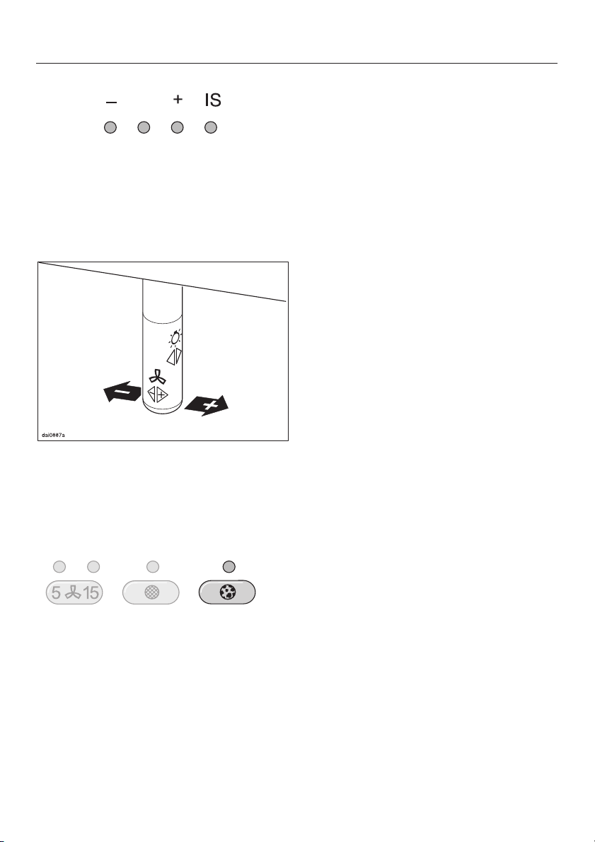
Operation
Joystick
This is used to operate the fan settings
and the lighting.
Switching on the fan
^ Press the joystick once to the right.
The fan runs at power level "II".
The second fan setting indicator will
light up.
When frying or cooking food with a
strong aroma, you may wish to select
the Intensive setting (yellow indicator
light) for a short period.
Switching the fan off
Press the joystick repeatedly to the
^
left until the fan switches off and the
fan setting indicator lights have all
gone out.
or
Press and hold the joystick to the left.
^
The fan setting indicator lights will go
out.
Selecting the power level
^
Press the joystick repeatedly to the
right to select a higher power level,
and to the left to select a lower power
level.
The relevant fan setting indicator will
light up.
Depending on the intensity of the
cooking vapours, levels "I" to "III" (green
indicator lights) are usually sufficient for
normal cooking.
41
Page 42

Operation
Switching the lighting on
The hob lighting can be switched on
and off independently of the fan.
^ Press the joystick once to the rear or
to the front to switch it on.
The lighting will come on at maximum
brightness.
Switching the lighting off
Press the joystick once to the rear or
^
to the front to switch it off.
Safety cut-out
Should the cooker hood be left on, the
fan will switch off automatically after
10 hours. The lighting will remain on.
Pressing the joystick once to the right
^
will switch the fan back on again.
Dimming the lighting
The brightness of the lighting can be
adjusted.
^
With the lighting switched on, press
and hold the joystick to the rear or
the front.
The brightness will gradually dim until
you release the joystick.
^
Pressing and holding it again will
gradually increase the brightness
until you release it.
^
If you keep the joystick pressed in,
the light will continually change
between bright and dim.
42
Page 43

Run-on option
It is advisable to run the fan for a few
minutes after cooking is finished to
neutralise any lingering odours in the
air.
The fan can be set to switch off
automatically after either 5 or
15 minutes:
Operation
To do this, press the grease filter
^
touch control and hold for about
3 seconds.
The grease filter indicator light goes
out.
In recirculation mode:
Press the run-on option touch control
^
whilst the fan is still running.
– Press once = The fan switches off
after 5 minutes
(left-hand indicator light).
– Press twice = The fan switches off
after 15 minutes
(right-hand indicator light).
To switch off the run-on option, press the
run-on option touch contol again. The
fan continues running.
Filter operating hours counter
The number of hours the appliance has
been in operation is stored in memory.
The indicator light for the grease filter
touch control will come on after 30 hours
of operation. The grease filters must
then be cleaned.
The operating hours counter for the
charcoal filter needs to be set to the
required time (see Setting and altering
the charcoal filter operating hours
counter).
The indicator light for the charcoal filter
control will light up after the cooker
hood has operated for the number of
hours set. The charcoal filters must be
replaced with new ones.
The filter operating hours counter must
then be re-set.
^
Press the charcoal filter touch control
for about 3 seconds.
The charcoal filter indicator light goes
out.
The filter operating hours counter must
then be re-set.
43
Page 44
Operation
Reading the filter operating hours
counter
To check the percentage of time set
already used:
Switch the fan on with the joystick.
^
Press the grease filter or the charcoal
^
filter touch control.
One or several of the power level touch
control lights will flash.
The number of flashing lights shows the
percentage of the operating time which
has already been used up.
1 light = 25 %
2 lights = 50 %
3 lights = 75 %
4 lights = 100 %
Setting and altering the grease filter
operating hours counter
You can set the operating hours
counter to suit the type of cooking you
do.
Select a short time if you roast or fry
–
a lot.
If you use very little fat for cooking,
–
select a longer time.
If you only cook occasionally we
–
recommend that you select a short
time, because grease which has built
up gradually over a long period of
time will harden on the grease filters
and make cleaning more difficult.
Altering the filter operating hours
counter
The operating hours counter for the
grease filter is set to 30 hours. This can
be lengthened or shortened. You can
choose 20, 30, 40 or 50 hours.
^
Switch the fan on with the joystick.
The number of operating hours used
remains in the memory, even when the
appliance is switched off or there is a
power cut.
44
^
Press the run-on option touch control
and the grease filter touch control at
the same time.
The indicator light for the grease filter
touch control and one of the lights for
the power level touch controls will flash.
Page 45

Operation
Setting and altering the charcoal
filter operating hours counter
(with recirculation mode)
The power level touch control lamps
show the time which has been set:
1st light from the left = 20 hours
2nd light from the left = 30 hours
3rd light from the left = 40 hours
4th light from the left = 50 hours
^ Use the joystick to select the desired
time.
Press to the left for a shorter operating
time, or to the right for a longer time.
The charcoal filters must be fitted for
the cooker hood to be used in
recirculation mode.
On delivery, the operating hours
counter for the charcoal filters is set to
unlimited.
For recirculation mode, the operating
hours counter needs to be set to the
required time:
^ Switch the fan on with the joystick.
^ Press the run-on option touch control
and the charcoal filter touch control
at the same time.
The indicator light for the charcoal filter
touch control and one of the lights for
the power level touch controls will flash.
^
Confirm the selection by pressing the
grease filter touch control.
If the procedure is not confirmed within
4 minutes of programming the steps,
the cooker hood will automatically
revert to the "old" data.
45
Page 46

Operation
The power level touch control lights
show the time which has been set:
1st light from the left = 120 hours
2nd light from the left = 180 hours
3rd light from the left = 240 hours
4th light from the left = unlimited
^ Use the joystick to select the desired
time.
Press to the left for a shorter operating
time, or to the right for a longer time.
^
Confirm the procedure by pressing
the charcoal filter touch control.
If the procedure is not confirmed within
4 minutes of programming the steps,
the cooker hood will automatically
revert to the "old" data.
46
Page 47

Before any cleaning or maintenance
work, disconnect the cooker hood
from the mains supply. Ensure that:
– it is switched off at the wall socket
and the plug removed (pull on the
plug, not the cable), or
– the fuse is withdrawn from the
fused spur connection unit, or
– the mains fuse is withdrawn, or
– the screw-out fuse is removed (in
countries where this is applicable).
A microfibre E-Cloth is available from
^
the Miele UK Spare Parts Department
which is suitable for cleaning
surfaces such as stainless steel,
glass, plastic and chrome without the
use of chemicals. It can be washed
300 times.
Housing
General notes
Cleaning and care
Avoid:
cleaning agents containing soda,
–
acids, chlorides or solvents,
abrasive cleaning agents, e.g.
–
powder cleaners or cream cleaners
and abrasive sponges, as well as pot
scourers or sponges which have
been used previously with abrasive
cleaning agents.
These will damage the surface
material.
Important for appliances with
stainless steel housing
Stainless steel surfaces can be cleaned
using a proprietary non-abrasive
cleaning agent designed specifically
for use on stainless steel.
To help prevent re-soiling, proprietary
conditioning agents for stainless steel
can also be used.
Apply sparingly with a soft cloth.
The surfaces and controls are
susceptible to scratches and
abrasion. Please observe the
following cleaning instructions.
^
All external surfaces and controls can
be cleaned using warm water with a
little washing up liquid applied with a
well wrung-out soft sponge or cloth.
^
Wipe the surfaces dry using a soft
cloth.
Do not use too much water when
cleaning the controls. Water could
penetrate into the electronics and
cause damage.
Controls
The controls may suffer
discolouration or damage if soiling is
left on them for too long. Remove
soiling straight away.
Observe the General notes on cleaning
earlier in this section.
Do not use stainless steel cleaning
agents on the controls.
47
Page 48

Cleaning and care
Grease filter
The re-usable metal filters remove solid
particles (oil, dust, etc.) from the
kitchen vapours, preventing soiling of
the cooker hood.
The DA 119 has one grease filter and
the DA 112 has two grease filters.
The grease filters should be cleaned
regularly (at least every 3-4 weeks) to
avoid a build-up of fat.
However, they should be cleaned
immediately if the grease filter touch
control light comes on.
An oversaturated filter is a fire
hazard.
Clean the grease filters -
^
by hand: with a soft nylon brush,
–
warm water and a little washing up
liquid.
in a dishwasher: place the filters
–
with the short side upright in the
lower basket, ensuring the spray arm
is not obstructed. Wash on a
65° programme.
Depending on the cleaning agent
used, cleaning the grease filters in a
dishwasher can cause permanent
discolouration to the surface of the
filter.
However, this will not affect the
functioning of the grease filters in
any way.
^ After cleaning, leave the filters to dry
on an absorbent surface before
replacing them.
^
To remove a grease filter, press the
locking clip in towards the middle of
the filter. Holding carefully, lower and
remove the filter.
Take care not to let the grease filter fall
onto the hob.
48
Page 49

Cleaning and care
When removing the filters for
^
cleaning, also clean off any residues
of oil or fat from the now accessible
housing to prevent the risk of fire.
When replacing the grease filters,
ensure that the locking clips are facing
down towards the hob.
If a filter has been replaced upside
down:
^ Insert a small screwdriver into the slot
as shown to disengage it. Do not let it
drop onto the hob below.
^
After replacing the grease filters,
press the grease filter touch control
for approx. 3 seconds to re-set the
operating hours counter.
The indicator light will go out.
^
If the grease filters are cleaned
before the operating hours counter
has reached its maximum, the grease
filter touch control should be pressed
for approx. 6 seconds to reset the
counter.
Fitting and replacing the
charcoal filter
If the cooker hood is connected for
recirculation, a charcoal filter (one on
the DA 119 or two on the DA 112) must
be inserted in addition to the grease
filters. Charcoal filters absorb normal
kitchen odours.
They are fitted in the canopy above the
grease filter.
Charcoal filters can be obtained from
your dealer or the Miele Spare Parts
Department.
See back cover for contact details, and
"Technical Data" for model number.
^ Before fitting or replacing the
charcoal filters, the grease filters
must first be taken out (see previous
section for instructions on how to do
this).
^ Two brackets (DA 119) or four
brackets (DA 112) have to be fitted
for securing the charcoal filter. See
the Installation Sheet supplied with
the cooker hood for instructions on
how to fit them.
^
Take the charcoal filter out of its
packaging.
There are two filters in every pack.
Only one of these is required for the
DA 119. When you have removed
one charcoal filter from the pack,
take care to re-seal the package
again properly. Otherwise the
remaining charcoal filter will
deteriorate and be less effective
when you need to start using it.
49
Page 50

Cleaning and care
Fit the charcoal filter into the bracket.
^
When fitting for the first time:
Set the operating hours counter to
^
suit your requirements
(see Operation - Setting and altering
the charcoal filter operating hours
counter).
If the charcoal filters are replaced
^
before the operating hours counter
has reached its maximum, the
charcoal filter touch control should be
pressed for approx. 6 seconds to
reset the counter.
Always replace the filters when the
charcoal filter touch control indicator
light comes on, or if they are no longer
effective in absorbing kitchen odours.
They should, however, be replaced at
least every 6 months.
^
After fitting the new charcoal filter(s),
press the charcoal filter touch control
for approx. 3 seconds to re-set the
operating hours counter.
The indicator light will go out.
50
Page 51

Changing a halogen lamp
Before any cleaning or maintenance
work, disconnect the cooker hood
from the mains supply. Ensure that:
– it is switched off at the wall socket
and the plug removed (pull on the
plug, not the cable), or
– the fuse is withdrawn from the
fused spur connection unit, or
– the mains fuse is withdrawn, or
– the screw-out fuse is removed (in
countries where this is applicable).
Exercise caution when changing
halogen lamps. They get very hot
during use and remain hot for some
time after being switched off. Do not
touch the surface directly when
changing a lamp, as grease
particles from your fingers will
adhere to the surface and damage
it. Please follow the manufacturer’s
instructions.
Cleaning and care
To access the halogen lamp, first
^
remove the lamp cover a.
^ Pull the old halogen lamp b out of its
socket and replace it with a new one.
^ Replace the lamp cover a carefully,
making sure it engages securely in
position.
Never use the lighting without the
lamp cover a in place; it has a filter
designed to cut out harmful rays.
51
Page 52

Appliance dimensions
DA 119
1) Extraction
2) Recirculation
3) Ventilation grille position for recirculation
Position:
The shaded area represents the wall
or ceiling area for the vent cut-out, and
for fitting the connection socket.
For recirculation mode, only a connection
socket needs to be fitted. The connection
socket is fitted in area a.
Connection for air extraction C 150 mm,
or C 125 mm with reducing collar.
Safety distance between hob and
cooker hood
For safety reasons a minimum safety
distance must be maintained
between the top of the cooker/hob
and the bottom of the cooker hood:
– 450 mm above electric cookers/
hobs
– 650 mm above gas cookers/hobs
– 650 mm above an open grill from
the Miele range.
See the Warning and safety
instructions for further information.
DA 112
52
When deciding on the safety distance
between the hob and cooker hood,
please note that
–
a distance of 650 mm above electric
cookers/hobs may be preferable to
give more working space under the
hood.
–
with a ceiling mounted hood you
must make sure that there is
sufficient space below the hood to
maintain the correct safety distance.
Page 53

Assembly parts
Assembly
53
Page 54

Assembly
a 2 protective sheets
for use when fitting the tower.
b 1 directional unit
(for recirculation mode only)
c 1 flexible aluminium hose for
connecting the directional unit to the
exhaust socket on the motor unit.
d 2 hose clips for securing the
exhaust ducting.
e 1 reducing collar for exhaust
ducting C 125 mm.
f 1 non-return flap for fitting into the
exhaust stub.
g Upper retaining plate for securing
the extension piece.
h Middle retaining plate for securing
the extension piece.
i Lower retaining plate for securing
the appliance unit.
10 screws 5 x 40 mm and
10 x S 8 plugs for securing the retaining
plates and the canopy to the wall.
The screws and plugs are designed
for use in solid walls.
For other types of wall construction,
alternative suitable fixings will be
required.
Make sure the wall is strong enough
to bear the weight of the cooker
hood.
2 x M 6 locking nuts for securing the
appliance unit.
j 2 brackets for DA 119, or
4 brackets for DA 112 for fitting the
charcoal filter in recirculation mode.
54
2 screws 3.9 x 7.5 mm for securing the
tower
4 screws 3.5 x 25 mm for securing the
canopy to the motor unit.
12 screws 3.5 x 16 mm for securing
the extractor in the canopy.
Page 55

Assembly
This appliance must only be
installed using the correct wooden
facings supplied by Miele.
1 allen key
for adjusting the appliance height
Joystick with fittings
1 lever for dismantling the tower.
Installation instructions
Installation instructions
See enclosed installation sheet for
instructions on how to install this
appliance.
Before installation, it is important to
read the information given on the
following pages as well as the
Appliance dimensions and Warning
and safety instructions at the beginning
of this book.
Dismantling
Should the appliance need to be
dismantled, follow the installation
instructions in reverse order as
described on the installation sheet.
A lever is supplied to assist with the
removal of the tower.
^
After loosening the fixing screws on
the tower, push the lever between the
tower and the extension piece to
lever the tower out of its fixings.
55
Page 56

Connection for air extraction
Danger of toxic fumes.
Please heed the Warning and Safety
instructions to avoid the danger of
toxic fumes.
The cooker hood should be installed
according to local building
regulations. Seek approval from the
building inspector where necessary.
The extraction ducting should be as
–
short and straight as possible.
To ensure efficient air extraction, the
–
diameter of the exhaust ducting
should not be less than 150 mm.
If exhaust ducting with a diameter of
less than 150 mm or flat ducting is
used, the noise level of the cooker
hood will increase and extraction will
be less efficient.
Where ducting is horizontal, it must
–
be laid to slope away at at least 1 cm
per metre.
This is to ensure that condensate
cannot drain back into the cooker
hood.
If the exhaust air is to be ducted into
–
the open air, the installation of a
telescopic wall vent is
recommended.
Only reduce the diameter of the
ducting if absolutely necessary, e.g.
where narrower ducting has already
been installed.
–
Only use wide radius bends. Tight
bends reduce the air throughput of
the cooker hood.
–
Only use smooth pipes or flexible
hoses made from non-flammable
materials for extraction connection.
56
–
If the exhaust air is to be ducted into
a vent flue, the ducting must be
directed in the flow direction of the
flue.
Page 57

Important:
If the exhaust ducting is to run through
rooms, ceiling space etc. where there
may be great variations in temperature
between the different areas, the
problem of condensation will need to
be addressed. The exhaust ducting
will need to be suitably insulated.
Condensate trap
In addition to insulating the exhaust
ducting, we recommend that a suitable
condensate trap is also installed to
collect and evaporate any condensate
which may occur.
When installing a condensate trap,
ensure that it is positioned vertically
and if possible directly above the
exhaust connection.
Connection for air extraction
57
Page 58

Electrical connection
All electrical work should be
undertaken by a suitably qualified
and competent person in strict
accordance with national and local
safety regulations.
Installation, repairs and other work
by unqualified persons could be
dangerous. The manufacturer can
not be held liable for unauthorised
work.
Ensure power is not supplied to the
appliance while installation or repair
work is being carried out.
The cooker hood is supplied for
connection to an a.c.
230 V single phase 50 Hz supply.
The voltage, rated load and fusing are
given on the data plate. This is visible
when the grease filters have been
removed. Ensure that these match the
household mains supply.
Connection should be made either by a
double pole fused spur connection unit,
or a fused plug and a suitable switched
socket. The On-Off switch should be
easily accessible after the appliance
has been built in.
When switched off there must be an
all-pole contact gap of 3 mm in the
switch (including switch, fuses and
relays according to EN 60 335).
If the socket is not accessible after
installation (depending on country) an
additional means of disconnection must
be provided for all poles.
For extra safety it is advisable to install
a residual current device (RCD) with a
trip current of 30 mA (in accordance
with DIN VDE 0664, VDE 0100
Section 739).
Do not connect via an extension lead.
Important UK
If the appliance is fitted with a
non-rewireable plug (BS 1363 UK) and
the socket outlets are not suitable for
the plug supplied, or if the existing plug
needs to be replaced by a new one, the
old plug will need to be cut off and an
appropriate plug fitted. The fuse carrier
and the fuse should be removed from
the old plug and disposed of. The old
plug should then be disposed of and
on no account inserted into any socket
elsewhere in the house (electric shock
hazard).
The fuse cover must be re-fitted when
changing the fuse and if the fuse cover
is lost the plug must not be used until a
suitable replacement is obtained.
The colour of the correct replacement
cover is that of the coloured insert in
the base of the plug or the colour that is
embossed in words in the base of the
plug (as applicable to the design of
plug fitted).
Replacement fuses should be ASTA
approved to BS 1362 and have the
correct rating.
Replacement fuses and fuse covers
may be purchased from your local
electrical supplier or Miele Service
agent.
58
Page 59

Important
The wires in the mains lead are
coloured in accordance with the
following code:
Green/yellow = earth
Blue = neutral
Brown = live
If the appliance is to be connected via
a plug and socket, please note the
following:
As the colours of the wires in the mains
lead of this appliance may not
correspond with the coloured markings
identifying the terminals in your plug,
proceed as follows:
^ The wire which is coloured green and
yellow must be connected to the
terminal in the plug which is marked
with the letter E or by the earth
symbol - or coloured green or
green and yellow.
Electrical connection
^ The wire which is coloured blue must
be connected to the terminal which is
marked with the letter N or coloured
black.
^
The wire which is coloured brown
must be connected to the terminal
which is marked with the letter L or
coloured red.
WARNING:
THIS APPLIANCE MUST BE
EARTHED
59
Page 60

After sales service
In the event of a fault which you cannot
correct yourself, or if the appliance is
under guarantee please contact:
Your Miele Dealer
–
or
The Miele Service Department (see
–
back cover for address).
When contacting the Service
Department, please quote the model
and serial number of your appliance.
These are shown on the data plate
which is visible when the grease filter is
removed.
Please note that telephone calls may
be monitored and recorded to
improve our service.
60
Page 61

Total rated load
DA 119. . . . . . . . . . . . . . . . . . . . 240 W
DA 112. . . . . . . . . . . . . . . . . . . . 260 W
Fan. . . . . . . . . . . . . . . . . . . . . . . 200 W
Hob lighting
DA 119. . . . . . . . . . . . . . . . . . 2 x 20 W
DA 112. . . . . . . . . . . . . . . . . . 3 x 20 W
Voltage
UK, IRL, NZ, ZA . . . . . . . . . . AC 230 V
AUS . . . . . . . . . . . . . . . . . . . AC 240 V
Frequency. . . . . . . . . . . . . . . . ~ 50 Hz
Fuse rating (UK). . . . . . . . . . . . . . 13 A
Fuse rating (IRL). . . . . . . . . . . . . . 10 A
Electrical cable length . . . . . . . . 1.5 m
AUS, NZ:
Plug rating . . . . . . . . . . . . . . . . . . 10 A
Technical data
Test marks . . . . . . . . . . . Electric safety
. . . . . . . . . . . . . . . . . . . . . C-Tick-Mark
Electrically suppressed
according to AS/NZS 1044
Charcoal filter:
Miele charcoal filter DKF 10;
DA 119: one required;
DA 112: 2 required
616263
Page 62

Page 63

Page 64

Änderungen vorbehalten / Alteration rights reserved / 3503
Dieses Papier besteht aus 100 % chlorfrei gebleichtem Zellstoff und ist somit umweltschonend.
This paper consists of cellulose which has been bleached without the use of chlorine.
M.-Nr. 05 934 060 / 01
 Loading...