

Page 1

ScanWizardTM Pro TX
Reference Manual
Contents
• Introduction
• The Preview Window
• The Settings Window
• Advanced Image Correction T ools
• The Information Window
• The Job Panel Window
Page 2

Microtek
ScanWizard Pro TX
Reference Manual
for Windows & Mac OS
Page 3

Copyright
2003 by Microtek International, Inc.
All rights reserved.
Trademarks
Microtek™, Artix™, ScanWizard™ Pro TX, and ArtixScan™ are trademarks of Microtek International, Inc.
Macintosh® and Apple® are trademarks or registered trademarks of Apple Computer , Inc. Windows® is a
registered trademark of Microsoft Corporation. All other products or name brands are trademarks of their
respective holders.
Important
Documents that you scan may be protected under copyright law. The unauthorized use of such documents
could be a violation of the rights of the copyright holder. Micr otek bears no responsibility for the unauthorized
use of copyrighted materials.
T o obtain optimal results from the Micr otek scanning software and user's manual, you should be familiar with
such Windows concepts as pointing, clicking, dragging, and selecting from menus and dialog boxed. If these
things are new to you, refer to your Microsoft Windows User's Guide.
February 2003
Microtek Lab, Inc.Microtek Lab, Inc.
Microtek Lab, Inc.
Microtek Lab, Inc.Microtek Lab, Inc.
16941 Keegan A venue
Carson, CA 90746
USA
TEL: 310-687-5800
FAX: 310-687-5950
http://www.microtekusa.com
Microtek International, Inc.Microtek International, Inc.
Microtek International, Inc.
Microtek International, Inc.Microtek International, Inc.
6, Industry East Road 3
Science Based Industrial Park
Hsinchu, 30077, Taiwan
TEL: 886-3-5772155
FAX: 886-3-5772598
http://www.microtek.com
ii
MicrMicr
otek Eurotek Eur
Micr
otek Eur
MicrMicr
otek Eurotek Eur
Klompenmaker Str. 76 3194DE
Hoogvliet-RT
The Netherlands
TEL: 31-10-2425688
FAX: 31-10-2425699
http://www.microtekeurope.com
ope B.Vope B.V
ope B.V
ope B.Vope B.V
..
.
..
Page 4

Contents
Introduction 1
ScanWizard Pro TX: The Interface ......................................................................... 2
Launching ScanWizard Pro TX................................................................................ 3
Using the Scan mode .........................................................................................3
Using the Batch mode........................................................................................ 3
Exiting from ScanWizard Pro TX.............................................................................. 4
The Preview Window 5
The File Menu .............................................................................................................. 6
The Working Folder Concept ............................................................................ 6
New Working Folder ........................................................................................... 7
Load ScanWizard Working folder .................................................................... 7
Save Working Folder As..................................................................................... 7
Show Current Working Folder Path ................................................................. 8
Quit..........................................................................................................................8
The Scanner Menu .................................................................................................... 9
Scanner Model .................................................................................................... 9
Current Scanner Info ........................................................................................ 10
Scanner Probe ...................................................................................................1 0
Scanner Driver Manager (Macintosh only) ................................................. 11
Scanner Control .................................................................................................1 3
The View Menu ......................................................................................................... 14
Prescan Image #n..............................................................................................14
Zoom In/Out ........................................................................................................15
Resize Window to Fit ........................................................................................15
Bring Settings Window to Front .....................................................................1 6
Show/Hide Info/Job Panel/All Tag Windows .............................................. 16
Show/Hide High (White) & Low (Black) Value Markers ...........................1 6
About (Macintosh only) ................................................................................... 1 6
The Preferences Menu ........................................................................................... 17
Scan Material ..................................................................................................... 17
Film Size ............................................................................................................... 18
Color Matching Setup ......................................................................................1 9
White/Black Points Setup ............................................................................... 23
Auto Clipping tab.......................................................................................... 23
Output Levels tab .........................................................................................24
Highlight and Shadow Markers Value tab.............................................. 24
iii
Page 5

Cursor Auxiliary Lines .......................................................................................25
Prescan Setup .................................................................................................... 26
Monitor Gamma Setup (PC only) .................................................................... 27
Invert ....................................................................................................................28
Retain Scan Module after Scan (Mac only) ................................................ 29
More .....................................................................................................................29
Keep Overview Image (PC only) ................................................................ 30
Smoked Glass Background ........................................................................30
Warn if No Holder is Inserted....................................................................30
Auto Focus for Final Scan ..........................................................................31
Auto Overview............................................................................................... 31
Working Color Space (Mac)/Color Space Mode (PC) ..........................3 1
Scan Quality .................................................................................................. 31
Best Quality Multiple Sampling................................................................. 31
Interpolation Mode ...................................................................................... 33
Memory Usage (Mac only)......................................................................... 33
Default Orientation ...................................................................................... 3 3
Scratch Directory (Mac only) ....................................................................3 4
Thumbnail Size (PC only) ............................................................................. 34
The Correction Menu ............................................................................................... 34
The Help Menu ..........................................................................................................35
The Toolbar ................................................................................................................ 36
Scan Frame tool .................................................................................................3 7
Zoom tool ............................................................................................................. 39
Pane tool ............................................................................................................. 40
Dropper tool........................................................................................................ 41
The Tag Window tool ....................................................................................... 42
To create a tag window ..............................................................................42
To close tag window(s) ............................................................................... 42
Adjusting shadow & highlight with Magic Diamonds.......................... 43
Adjusting color cast with Magic Diamonds (LCH mode only) ............43
The White & Black Eyedropper tool ............................................................. 43
To create the White and Black Eyedropper tool ..................................43
Adjusting shadow & highlight with White & Black
Eyedropper tools .......................................................................................... 44
Color information preview in pixel ................................................................. 44
To restore original settings .............................................................................4 5
Overview, Prescan, Scan ........................................................................................46
Overview button ................................................................................................. 46
iv
Page 6

Prescan button .................................................................................................. 46
Scan button ........................................................................................................47
Rulers, Unit of Measurement ................................................................................. 48
Preview Area..............................................................................................................49
Auxiliary information and Handy buttons ...........................................................5 0
Prescan image resolution ................................................................................50
Zoom in/out scale .............................................................................................. 50
Zoom-in ................................................................................................................50
Zoom-out ............................................................................................................. 50
Toggle for momentary flashing of White and Black Markers.................. 50
The Settings Window 51
Elements of the Settings window .........................................................................51
Job............................................................................................................................... 54
Type ............................................................................................................................. 55
RGB.......................................................................................................................55
Grayscale ............................................................................................................ 55
CMYK ....................................................................................................................55
Lab Color..............................................................................................................5 5
Web/Internet Colors .........................................................................................56
256 Colors (Default)/256 Colors (Custom) ..................................................... 56
Line art .................................................................................................................5 6
Black-and-White Diffusion ..............................................................................56
Resolution settings .................................................................................................. 57
A. Resolution list box ........................................................................................ 57
B. Resolution unit .............................................................................................. 58
Scan Frame and related settings.......................................................................... 59
Scan Frame settings .........................................................................................59
Scaling Setting ................................................................................................... 60
Output settings .................................................................................................. 61
Image Size ..................................................................................................................6 1
Unit of Measurement............................................................................................... 61
Scan Frame options ................................................................................................. 62
Fixed Scan Frame .............................................................................................. 62
Fixed Output Size...............................................................................................62
Keep Proportion .................................................................................................6 2
Transform ....................................................................................................................63
Scanner Profile .......................................................................................................... 64
Image Category......................................................................................................... 65
v
Page 7

Advanced Image Correction Tools 67
The LCH Color Model ............................................................................................... 68
AIC Tools in LCH vs Native Color Mode ...............................................................6 9
AIC Tools and your Image Type............................................................................. 70
Workflow for Optimizing Images ............................................................................ 71
Accessing the AIC Tools .........................................................................................7 3
Elements of the Advanced Image Correction screen ......................................74
The Action Buttons and User-Defined Settings................................................ 75
Default button ....................................................................................................75
Revert button ......................................................................................................75
Add to Menu button ..........................................................................................76
Cancel button ..................................................................................................... 76
OK button ............................................................................................................. 76
The Reset button............................................................................................... 7 7
Loading/retrieving user-defined AIC settings .................................................... 78
Removing user-defined AIC settings .................................................................... 78
Dynamic Range tool .................................................................................................7 9
Eyedropper tools ............................................................................................... 80
White & Black Points tool (LCH color mode)......................................................81
Eyedropper tools ............................................................................................... 82
The W&B Points dialog box in Native color mode .................................... 83
Gradation tool ............................................................................................................84
How to read the curve...................................................................................... 84
The Gradation dialog box................................................................................ 8 5
Eyedropper tool (Mac only) ............................................................................ 87
Color Cast tool ........................................................................................................... 88
Eyedropper tool ........................................................................................................8 9
Saturation tool ...........................................................................................................9 0
Selective Color tool ..................................................................................................9 1
How to use the Selective Color tool .....................................................................9 2
Tone Curve tool .........................................................................................................9 7
Filter tool .....................................................................................................................99
Blur filters.......................................................................................................... 100
Sharpen filters .................................................................................................. 100
Edge Enhancement filter............................................................................... 101
Emboss filter .....................................................................................................101
Unsharp Masking (USM) filter ......................................................................102
Gaussian Blur filter .......................................................................................... 103
Brightness and Contrast tool (Native Color Mode only) ................................ 104
Color Correction tool (Native Color Mode only) ............................................... 105
vi
Page 8

The Information Window 106
Mouse Pointer Position......................................................................................... 106
Color Input Meter ...................................................................................................10 7
Color Output Meter.................................................................................................107
Color Meter Options ...............................................................................................108
Sample Display Area..............................................................................................108
Creating Color Tag Windows................................................................................109
The Job Panel Window 111
Image type list box .................................................................................................11 2
Thumbnails of overview images.......................................................................... 112
Checked scan job ................................................................................................... 112
Current scan job .....................................................................................................1 12
Tool bar buttons ......................................................................................................11 2
Selecting Multiple Scan Jobs ............................................................................. 113
Editing Multiple Scan Jobs ..................................................................................11 3
Appendix 115
A: Color Matching for Advanced Users 116
For Macintosh users..............................................................................................116
Calibrating your monitor.................................................................................116
Setting up the System (Monitor) Profile .....................................................11 6
Using images in third-party applications ...................................................11 7
A. Using ColorSync-savvy applications ................................................. 117
B. Using non-ColorSync-savvy applications ........................................118
For Windows users.................................................................................................119
System Monitor Profile Setup .......................................................................119
ICC Profile-Aware vs. non-ICC Profile-Aware applications .................... 120
Color Matching Setup using ICC Profile-Aware applications ................ 121
Color Matching Setup using non-ICC Profile-Aware applications .......1 22
Color Matching Setup dialog button functions ........................................ 123
Add Profiles button ......................................................................................... 123
Info button ........................................................................................................123
Preview button .................................................................................................1 23
Refresh button ................................................................................................. 123
vii
Page 9

B: Kodak Color Management System 124
KCMS Overview ....................................................................................................... 124
Some Background Information ....................................................................12 4
The Idea Behind Color Management ..........................................................124
How Color Management Works ...................................................................12 5
How CMS Translates between Devices .....................................................125
What are Device Color Profiles ....................................................................12 6
Where Do Color Profiles Come From?..........................................................126
A Word about Source and Destination ......................................................1 27
Controlling UCR & GCR........................................................................................... 128
Controlling UCR and GCR with Professional CMYK Profiles....................128
Some Background........................................................................................... 128
UCR......................................................................................................................129
Advantages & Disadvantages to UCR ........................................................129
GCR......................................................................................................................130
Advantages & Problems of GCR ...................................................................1 30
Professional CMYK Profiles Package.................................................................131
What You Get with Professional CMYK Profiles Package ......................1 31
EUROPEAN PRINTING ST ANDARDS: ...........................................................131
U.S. CMYK SWOP PRINTING ST ANDARDS: ................................................132
JAPANESE PRINTING STANDARDS:............................................................132
Check With Your Service Provider...............................................................133
C: Available File Formats for “Scan to File” Function” 134
D: Photoshop Color Settings 136
Calibrating your monitor........................................................................................ 137
RGB Setup with your monitor ICC profile ........................................................... 140
CMYK setup information .......................................................................................1 41
Profile setup information ......................................................................................1 42
viii
Page 10

Introduction
This reference manual describes the various commands and features found in
the ScanWizard Pro TX scanning software for Macintosh.
The reference information is organized in four parts, corresponding to the four
major windows of the program:
••
Preview windowPreview window
•
Preview window
••
Preview windowPreview window
••
Settings windowSettings window
•
Settings window
••
Settings windowSettings window
••
Information windowInformation window
•
Information window
••
Information windowInformation window
••
Job Panel windowJob Panel window
•
Job Panel window
••
Job Panel windowJob Panel window
Reference: The Preview window 1
Page 11
ScanWizard Pro TX: The Interface
ScanWizard Pr o TX consists of four major windows: Preview, Settings,
Information, and Job Panel.
All four windows appear automatically after ScanWizard Pro TX is started up (in
either LCH or Native color mode) for the first time. You may hide or show the
InformationInformation
Information window by clicking on the Hide/Show toggle commands in the View
InformationInformation
PrPr
menu of the
evieweview
Pr
eview window.
PrPr
evieweview
Preview window
has commands and
tools for controlling
the scanner
Settings
window under
“ LCH” Color
Space Mode
Settings window
under “ Native”
Color Space Mode
Information window
under “ LCH” Color
Space Mode
Information window provides color
information on a selected area of the
Information window
under “ Native” Color
Space Mode
image
Settings window contains the scanning
parameters for the output image. It also
provides the advanced image correction
AIC tools for image editing in the scan
stage.
2 Microtek ScanWizard Pro TX for Mac & PC
provides functions for managing scan jobs
Scan Job window
Page 12

Launching ScanWizard Pro TX
ScanWizard Pr o TX operates in two modes, namely, the
modes:
1) The
2) The
Using the Scan mode
The
compatible image-editing software such as Adobe Photoshop.
T o operate ScanW izar d Pro TX in the
software. When the software program is ready, go to the File menu, and choose
Import Import
Import or
Import Import
This will automatically launch ScanWizard Pro TX. The four major windows that
form the interface of ScanWizard Pro TX will then appear on your screen.
Using the Batch mode
The
individually or in “batches”. It auto scans your multiple selections of originals
and directly save them to a predesignated file.
ScanScan
Scan ( or s ca n -t o -application) mode, in which ScanWizard Pro TX is
ScanScan
“acquired” through an image-editing software program like Adobe
Photoshop. The output images are scanned and directly delivered
(individually or in batches) to the image-editing application for further
processing.
BatchBatch
Batch ( o r scan-to-file) mode launches the ScanWizard Pro TX as a stand-
BatchBatch
alone application from the desktop program icon (and/or from the Apple
menu for Mac/Windows Start menu for PC). The output images are scanned
and saved to files individually or in batches.
Scan Scan
Scan mode r efers to launching ScanW izar d Pr o TX from a TWAIN
Scan Scan
ScanScan
Scan mode, launch your image-editing
ScanScan
AcquireAcquire
Acquire (depending on the software you are using) from its submenu.
AcquireAcquire
BatchBatch
Batch mode of operating ScanWizard Pro TX allows you to set up scan jobs
BatchBatch
Scan Scan
Scan an d the
Scan Scan
BatchBatch
Batch
BatchBatch
T o launch ScanW izard Pro TX in the
Mac users:
Click your ScanWizard Pro TX application desktop or the Applet located in the
ScanWizard Pr o TX folder. You can also start the program fr om the Apple menu.
PC users:
Click on the ScanWizard Pro TX program icon on your desktop or go to the
Start menu|Program|Microtek ScanWizard Pro TX|Microtek ScanWizard Pro TX
6.0.
BatchBatch
Batch mode-
BatchBatch
Reference: The Preview window 3
Page 13

Exiting from ScanWizard Pro TX
PrPr
T o exit ScanW izard Pro TX, go to the
choose the Quit command. You may also quit the pr ogram by-
Mac users:Mac users:
Mac users: Press the
Mac users:Mac users:
PC users:PC users:
PC users: Click on the
PC users:PC users:
Apple+QApple+Q
Apple+Q combination keys on your keyboard.
Apple+QApple+Q
CloseClose
Close button at top-right corner of the
CloseClose
evieweview
Pr
eview window , and from the File menu,
PrPr
evieweview
PrPr
evieweview
Pr
eview window.
PrPr
evieweview
4 Microtek ScanWizard Pro TX for Mac & PC
Page 14
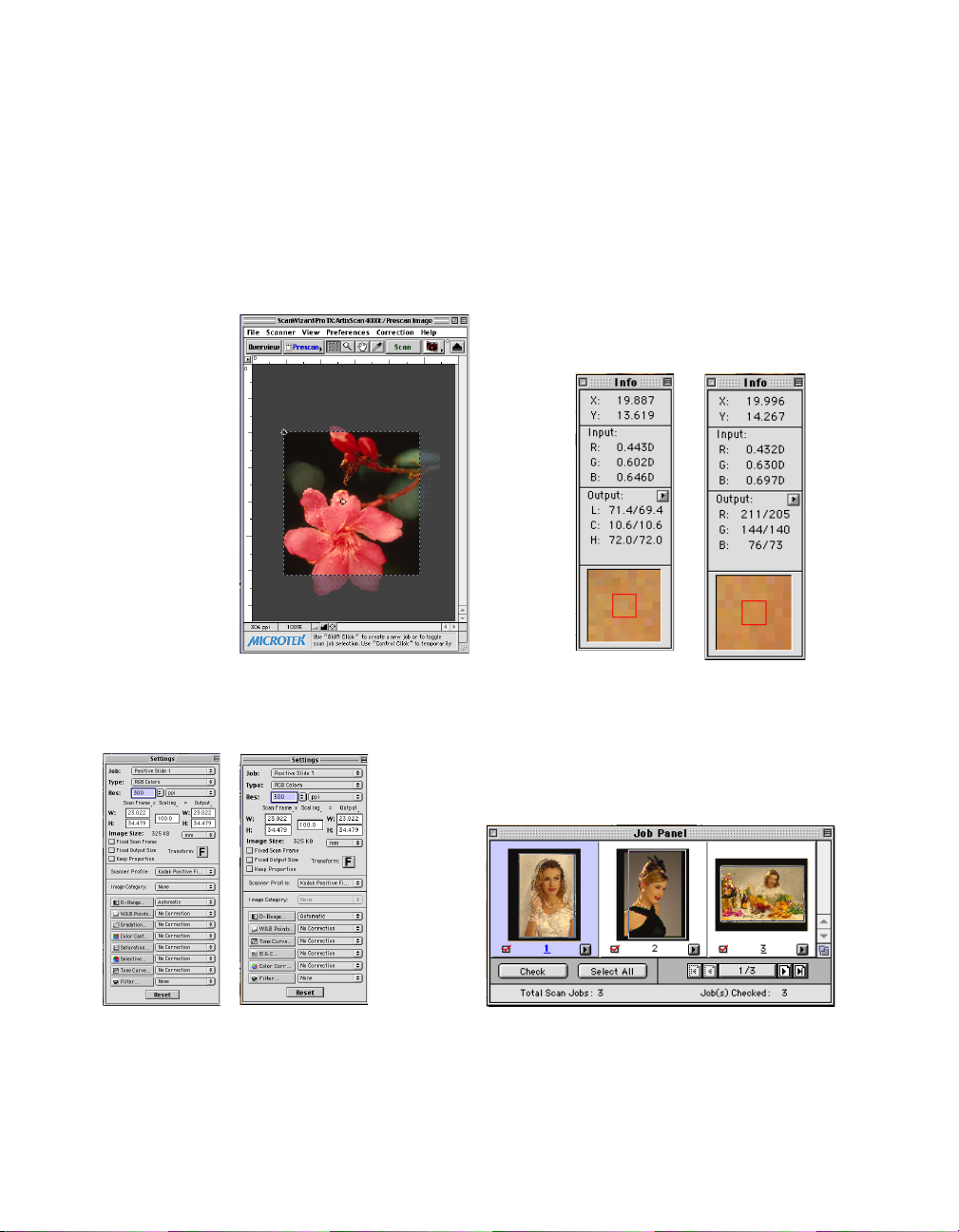
The Preview Window
PreviewPreview
The
Preview window is the primary window of ScanWizard Pro TX.
PreviewPreview
resolution image of the
Previews the entire film
Unit of
Measurement:
Choose from inch,
cm, mm, point, pica,
& pixel
Ruler
Prescan button:
Previews a high-
selected scan job
Overview button:
holder
Prescan Frame option
showing “Scan Frame”
setting icon
Prescan Frame Option:
When this option is set to
“Scan Frame,” only the area
enclosed by the Scan Frame
is prescanned & scanned
Toolbar: (Left to right) Scan
Frame, Zoom, Pane, and Tag
Windows
Overview image of the
currently selected scan
job in Job Panel
Scan button: Starts
the scanning
process.
Scan Material icon: Selects
the type of scan material
(Negative or Positive Film)
Film Size icon:
Selects film size for
120 film (6 x 9 cm)
suported scanners
Eject button: Ejects
the filmstrip/slide/
APS cartridge
holder from the
scanner
Scan Frame:
Selects the area
for final scan. Drag
on corner/side to
resize
Prescan image
resolution/zoom
status
Status bar: Provides
tips relative to the
selected tool in the
Toolbar
Handy buttons for
Zoom in/out
Switch for momentary
flashing of White & Black
Points Markers
White & Black
Points Markers:
Pinpoint to the
white & black
points of current
prescan image
Window Corner:
Drag to proportionally resize
the Preview window
Reference: The Preview window 5
Page 15

The File Menu
(Macintosh) (Windows)
The File Menu lets you do the following:
• Create a new working folder for saving custom-made scanning settings
Load previously saved scanning settings in a working folder and apply to
current scan session
• Save a modified working folder to another folder for future use
• Show the location of the working folder currently in use
• Exit ScanWizard Pro TX
The Working Folder Concept
The ScanWizard Pr o TX Working Folder is a tool that helps you enhance your
scanning productivity, especially when you have to perform several scanning
jobs of the same type of originals. All of your favorite image setting context for
previews or prescans, including AIC adjustments are automatically saved and
kept in a default or user-defined Working Folder. Several sets of settings in
various contexts can be saved. The accumulated settings are then retrieved and
loaded into ScanWizard Pro TX, and auto-applied to a new set of originals (of
the same type) during subsequent scanning sessions. This saves your time from
performing needless repetitive adjustments.
6 Microtek ScanWizard Pro TX for Mac & PC
Page 16

New Working Folder
This command creates a new working folder where a new set of custom image
settings is saved.
To create a new working folder:
1. Choose New Working Folder from the File menu.
2. When the browser dialog box appears, create a new folder name in the edit
box.
Load ScanWizard Working folder
This command loads a previously saved working folder into your current scan
session. The loaded working folder becomes the default settings for the current
scan session.
To load a working folder:
1. Choose Load Working Folder from the File menu.
2. When the browser dialog box appears, select the folder to be loaded, and
click the Open button at the bottom of the dialog box.
Save Working Folder As
This command lets you save a modified copy of the current working folder to a
separate or new location. The settings of the current working folder are saved
first and then copied and switched to the new location. This is particularly useful
when you want to work on a new working folder based on the settings of the
current working folder.
To save a working folder:
1. Choose Save Working folder As from the File menu.
2. When a dialog box appears, choose the folder where the scan settings will be
saved. Subsequent scan jobs setting are then saved to the specified folder.
Reference: The Preview window 7
Page 17

Show Current Working Folder Path
This command shows the foldername and location of the working folder in use
by the current scanning session. By default, the current working folder has the
same name as your scanner model (eg., ArtixScan 4000t), and is located in the
same folder where your ScanWizard Pro TX is located. When you load or create
a new working folder, the loaded or newly created folder then becomes the
current working folder.
T o show the curr ent working folder: Choose Show Curr ent Working folder Path
from the File menu.
Quit
This command lets you exit ScanWizard Pro TX.
8 Microtek ScanWizard Pro TX for Mac & PC
Page 18
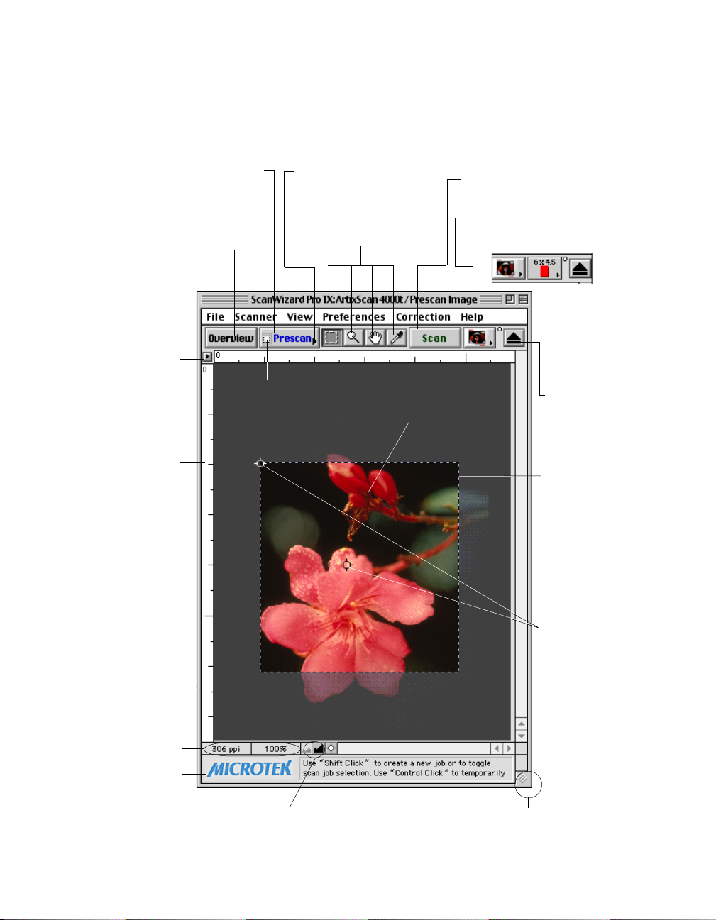
The Scanner Menu
(Macintosh)
(Windows)
The Scanner Menu lets you:
• Show your scanner model or select a scanner if you have multiple scanners
• Get information about your scanner
• Get scanner information on the SCSI/USB chain
• Easily manage the scanners being used by your system (Macintosh only)
• Power-saving contr ol during idle time
Scanner Model
The top item(s) of the scanner menu displays the scanner model currently in use
and its respective SCSI or USB ID number. If you have multiple scanners on your
system, all the scanners are shown with their respective SCSI or USB IDs, and the
current scanner is shown with a check mark.
Only one scanner can be accessed at a time. To switch among various scanners,
select the scanner to be used.
The scanner with its SCSI or USB ID
number is displayed. The current
scanner has a check mark
Reference: The Preview window 9
Page 19
Current Scanner Info
This command provides information about your current scanner . When you
choose this command, a dialog box appears showing the scanner model, the
SCSI or USB ID number, and the firmware version.
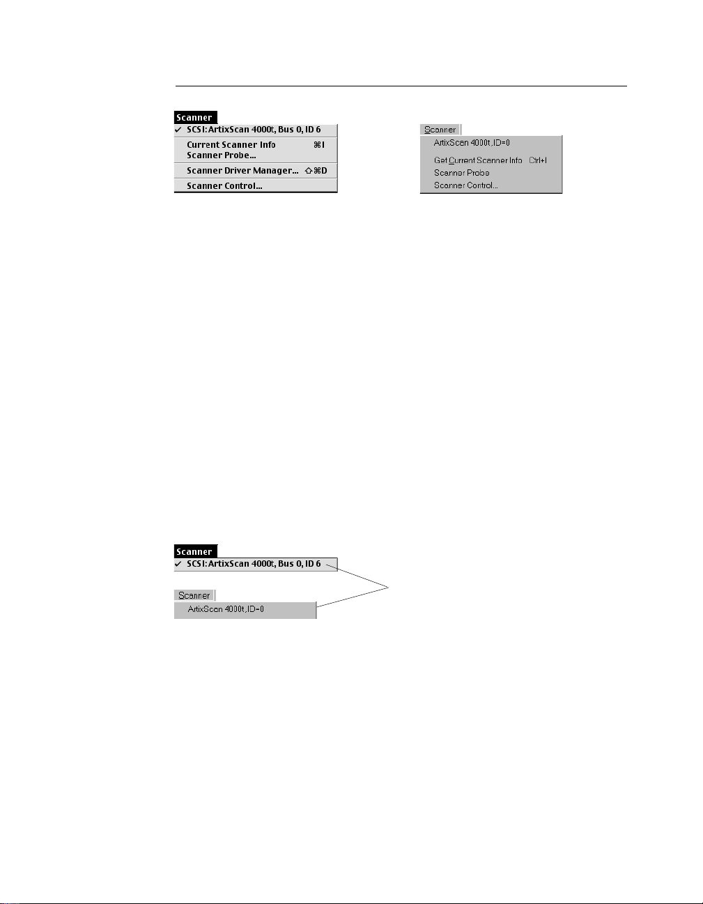
Scanner Probe
This command shows the scanner information on your SCSI/USB chain. If your
scanner does not show in the dialog box, make sure your scanner is connected
and turned on, and then click the Probe button. Please follow the scanner
hardware installation guide for proper procedures on connecting your scanner.
The SCSI/USB Chain dialog box
Select your interface
card here
Click on the Probe
button to update
information or mount
a SCSI device if it's
not showing in the
dialog box
Select your interface
card here
10 Microtek ScanWizard Pro TX for Mac & PC
(Macintosh)
(Windows)
SCSI devices are
shown with their
corresponding
SCSI ID numbers
Page 20
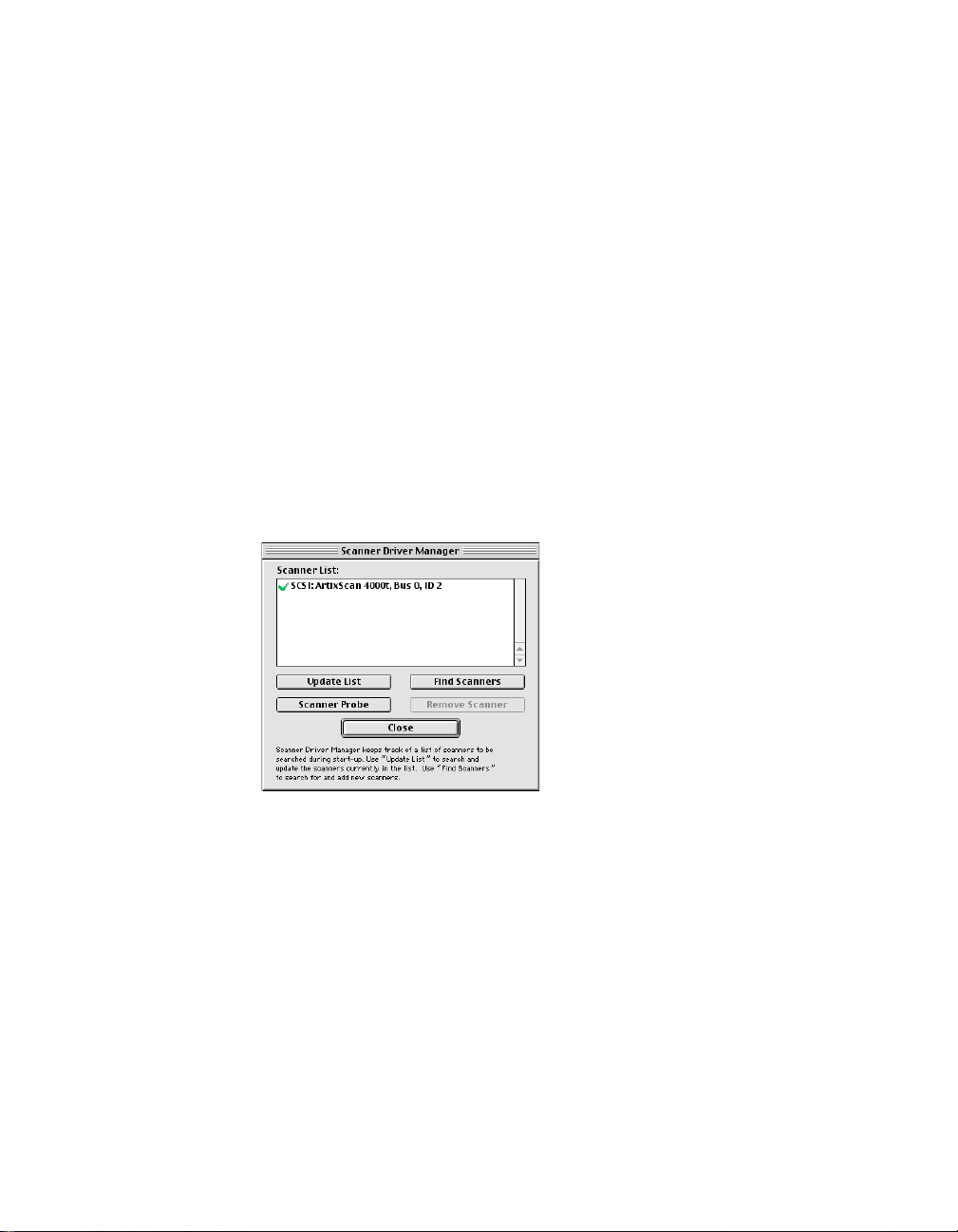
Scanner Driver Manager (Macintosh only)
The Scanner Driver Manager keeps track of the scanners being used on your
system and their corresponding bus/ID numbers. By keeping a record of this
information, the Scanner Driver Manager allows ScanWizard Pro TX to start up
faster, as searching for devices from other buses is no longer required.
When ScanWizard Pro TX is run for the first time right after installation, all preconnected powered-on scanners and corresponding SCSI/USB ID or SCSI/USB
bus are automatically detected and added to the Scanner List of the Scanner
Driver Manager dialog box.
Find Scanners button
Whenever you change the SCSI/USB ID or SCSI/USB bus of a scanner or
increase the number of connected scanners while ScanWizard Pro TX is
running, you need to add the new devices to the list by following the steps below.
1. Go to the Scanner menu in the Preview window , and choose Scanner Driver
Manager. A dialog box will appear showing the current scanner list and the
corresponding SCSI or USB bus/ID numbers of the scanners.
2. Click the Find Scanners button. Observe the newly found scanners being
appended to the scanner list.
::
NOTE
: Any previously listed scanner which is inactive (not turned on or removed
::
from the system) will remain in the list but is shown with a question mark (?).
3. Click the Close button to close the dialog box.
Reference: The Preview window 11
Page 21

Remove Scanner button
T o r emove a listed scanner from the Scanner List, do the following:
1. Choose Scanner Driver Manager from the Scanner menu.
2. Choose the scanner you wish to be removed from the list.
3. Click the RemoveScanner button.
4. Click the Close button to close the dialog box.
Update List button
The Update List button is used to refresh your scanner list. For instance, you may
have three scanners on your system, with two of them currently turned off.
When you choose Scanner Driver Manager, the dialog box may show a question
mark in front of the two scanners that have been turned off. In this case, simply
click the Update List button, and the scanner list will be refreshed and show only
the connected one on the list.
Clicking the Update List button produces faster results than clicking the “Find
Scanners” button. Update List simply searches the scanner models already on
your list, while Find Scanners looks through all the buses and does a more
thorough search of the system before giving you the results.
Scanner Probe button
See Scanner Probe command in the previous section.
12 Microtek ScanWizard Pro TX for Mac & PC
Page 22
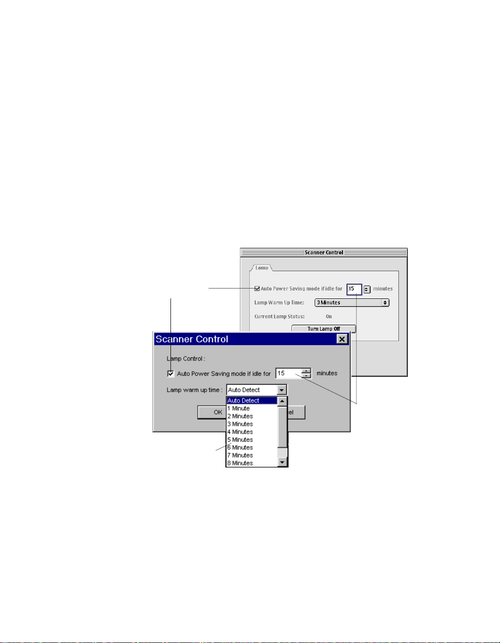
Scanner Control
The film scanner provides an energy-saving feature whereby the scanning lamp
switches to power-saving mode when the scanner remains idle for a defined
period of time. It will revert to full power mode as soon as the Overview,
Prescan, or Scan/Batch button is clicked. Aside from saving power, the feature
also helps extend the service life of the lamp and prevents the caking and
deforming of film being scanned due to long period of exposure to lamp heat.
The default idle time to induce the scanning lamp into power-saving mode and
the time needed for the lamp to warm up, revert to full power, and start the
scanning, opeation varies among scanner models. You may define your own idle
and warm-up time intervals or disable the feature altogether by clicking on the
“Scanner Control...” menu command. The following Scanner Control dialog box
will then display to allow you to change the default settings.
(Macintosh)
Uncheck check
box to disable
Power Saving
feature
Define warm-up time
required for lamp to
revert to full power mode
Define idle time
interval for Power
Saving mode
(Windows)
to take effect (60
minutes maximum)
Reference: The Preview window 13
Page 23
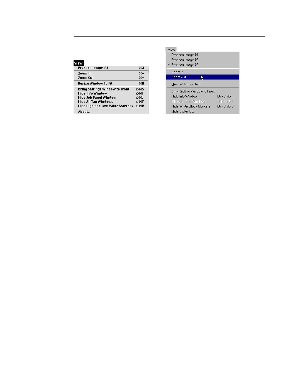
The View Menu
(Macintosh) (Windows)
The View menu lets you:
• Select a prescan view of an image
• Magnify or reduce (zoom in /zoom out) the prescan image
• Resize the Preview window to fit
• Bring the Settings window to the front
• Show or hide the Info, T ag, and Scan Job windows
• Show or hide the High (White) and Low (Black) V alue Markers
• Show the ScanWizard Pro TX splash screen
Prescan Image #n
This command is available only after performing a prescan of the overview
images in the Job Panel window. The number of commands indicates the total
available number of prescanned images. Select the appropriate command to
display the corresponding prescan image in the main Preview window for
further editing. The selected command is shown with a check mark to indicate
the image you are currently working and is on display.
Likewise, the Job Panel will highlight the image you have selected. You may also
make the selection from the Job Panel window instead of making it from the
View menu. Clicking directly on any of the multiple overview images in the Job
Panel will also display its corresponding prescan image in the main Preview
window.
14 Microtek ScanWizard Pro TX for Mac & PC
Page 24
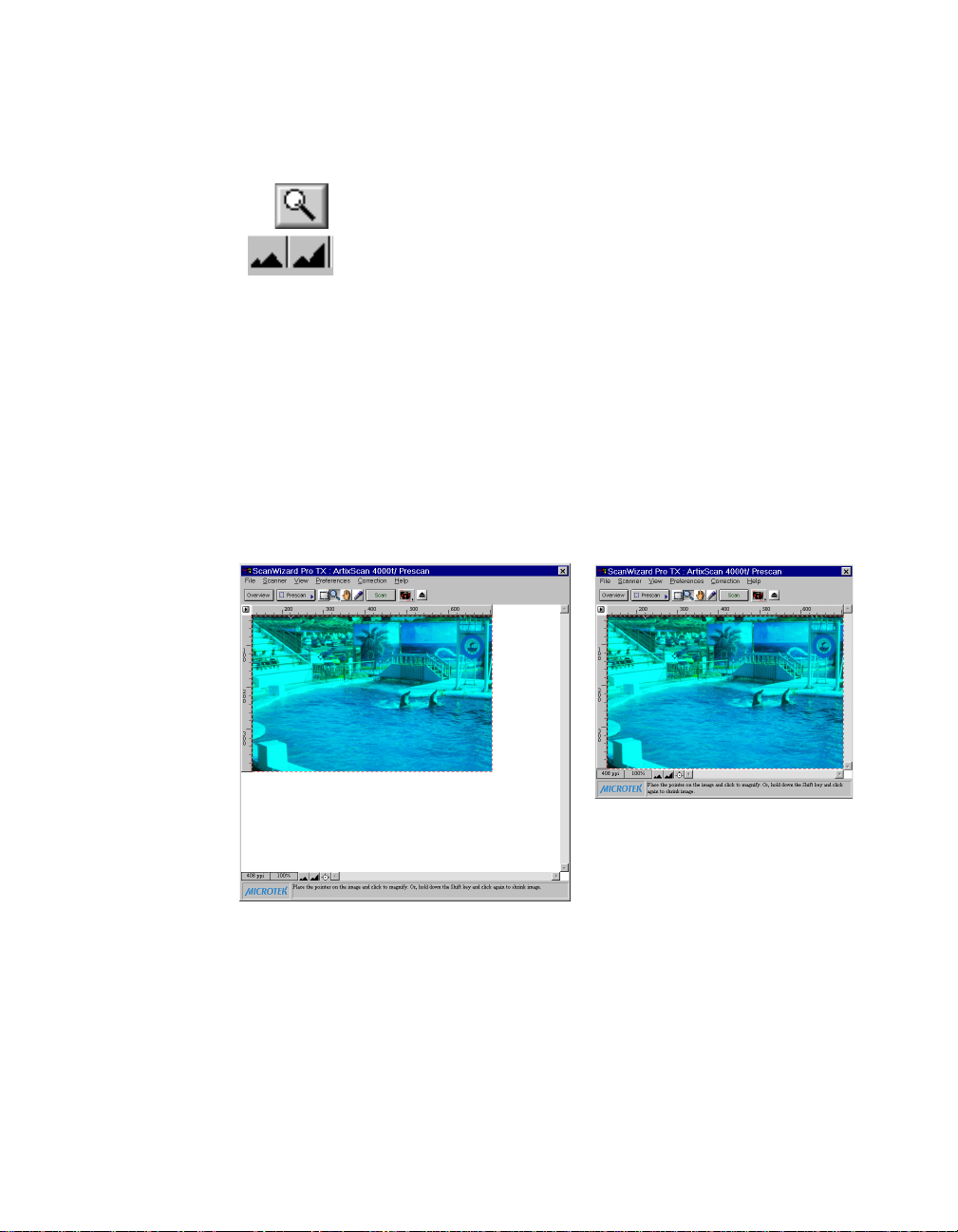
Zoom In/Out
These commands allow you to magnify (Zoom In) or reduce (Zoom Out) the
prescan or scanned image in the Preview window.
Alternatively, you can use the magnifying glass tool in the Preview
window's Toolbar or use the Handy buttons at the bottom of the
Preview window to accomplish the same effect.
Resize Window to Fit
This command trims an oversized Preview window to fit the prescan image size
under preview to provide more desktop space to display other ScanWizard Pro
TX windows. This is done without affecting the image size.
In the example below, the Preview window at the left is oversized with plenty of
extra idle spaces to its right and bottom. After executing the Resize command
from the View menu, the extra spaces are trimmed and the Preview window is
proportionally resized to accommodate the image size.
Before resizing
After resizing
Reference: The Preview window 15
Page 25

Bring Settings Window to Front
This command brings the Settings window to the forefront, which is useful if you
have the Settings window hidden behind other windows or if you have expanded
your Preview window so that the Settings window is hidden behind it.
Show/Hide Info/Job Panel/All T ag Windows
These commands allow you to toggle between showing or hiding the
Information, Job Panel window , and the Tag windows on your screen.
Show/Hide High (White) & Low (Black) Value Markers
These commands show or hide the Low & High V alue Markers (White & Black
Markers for Windows) in the Preview window. By default, the Markers are
shown in the form of a circular crossbar. A white circle in the middle represents
the Low Value (black point) Marker, and a black circle in the middle represents
the High V alue (white point) Marker .
About (Macintosh only)
This command displays the ScanWizard Pro TX splash screen and shows the
program's version number .
16 Microtek ScanWizard Pro TX for Mac & PC
Page 26
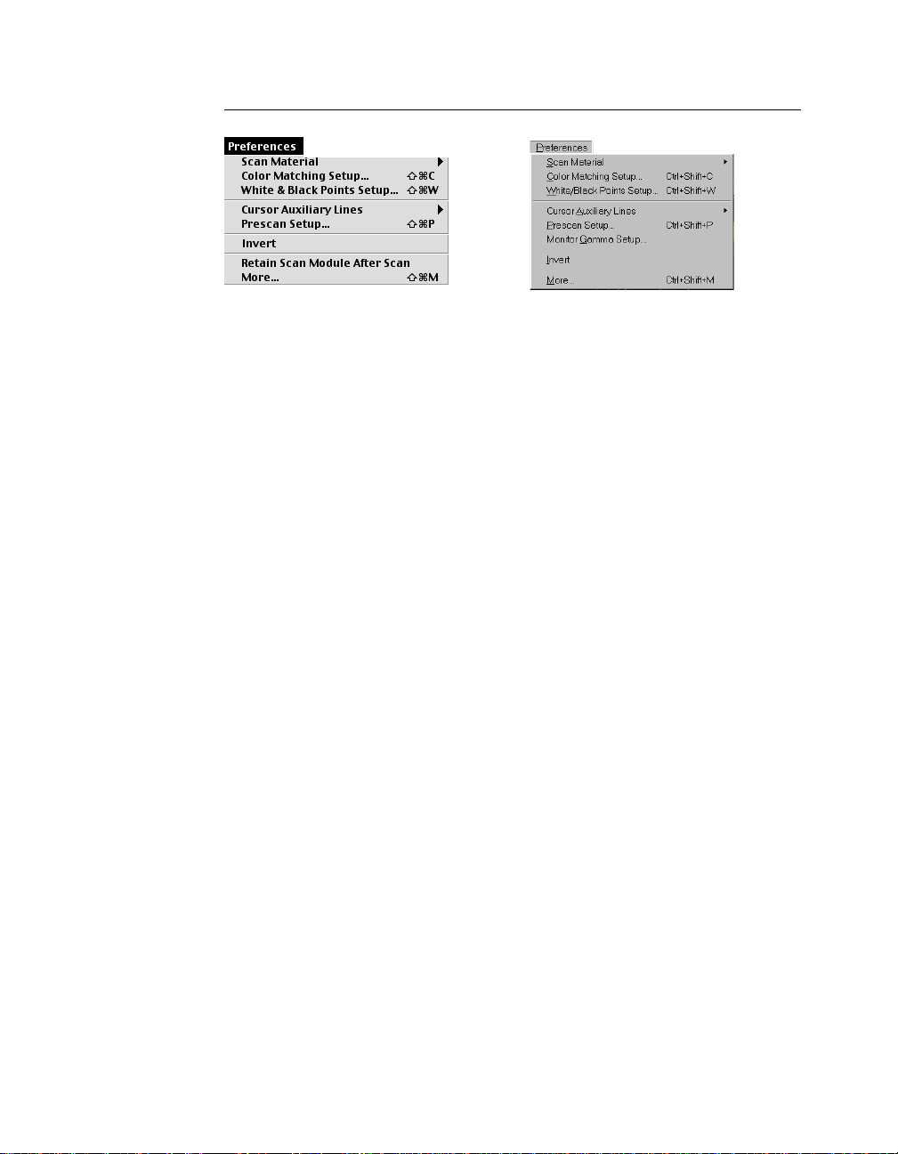
The Preferences Menu
(Windows)(Macintosh)
The Preferences menu lets you:
• Choose the correct scan material
• Choose the correct film size (for 6 x 9 cm film supported scanner only)
• Specify color matching parameters
• Set up White/black points
• Show/hide auxiliary cursor lines
• Control Prescan settings
• Create effects like invert
• Activate the smoked glass effect
• Set other options, such as specifying a working directory for files
• Activate Multiple-Sampling feature to maximize scan image quality (applicable to scanners that supports this feature only)
Scan Material
This command allows you to select the correct scan material. Scan materials can
be classified into two types:
• 35mm positive transparencies
• 35mm and APS negative films
Make sure you specify the correct scan material, or you will get inaccurate
scanning results.
Reference: The Preview Window 17
Page 27
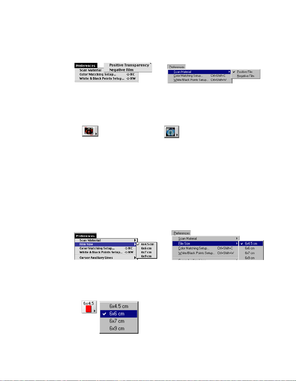
To choose your scan material:
1. Choose the Scan Material command in the Preferences menu. From the
submenu that appears, select your scan material; a check mark will appear
on the selected option.
(Windows)(Macintosh)
2. Alternatively , you can click the Scan Material icon from the Preview window
and then choose the correct scan material from the drop-down menu that
appears.
(Positive transparency)
(Negative film)
Film Size
This command allows you to select the correct film size for 6 x 9 cm film
supported scanners (e.g., ArtixScan 120tf). If your scanner does not support
scanning 6 x 9 cm film, the Film Size command will not display.
T o choose your Film Size:
1. When the 6 x 9 cm film holder is inserted, the Film Size command is
activated. You can choose the Film Size command in the Preferences menu.
Then select your film size; a check mark will appear on the selected option.
(Windows)(Macintosh)
2. Alternatively, you can click the Film Size icon from the Preview window and
then choose the correct film size from the drop-down that appears.
18 Microtek ScanWizard Pro TX for Mac & PC
Page 28
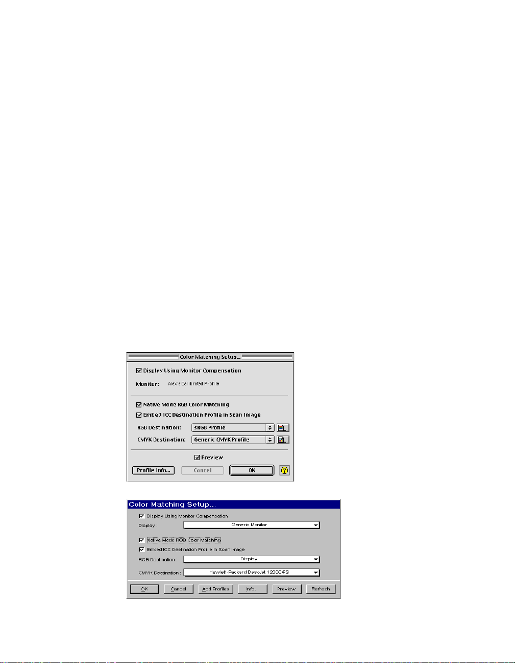
Color Matching Setup
Color Matching is an important feature of ScanWizard Pro TX that ensures
consistent color — from the initial input stage when an image is captured by the
scanner, to the final output stage when the image is output to your monitor or
printer through either the Kodak CMS with ICC profile standard or Apple
ColorSync™ technology (the latter applicable to Macintosh only).
Color matching is a critical component in the imaging process, because the color
space of your monitor is different from that of your printer (in terms of output
devices), just as the color space for RGB mode is different from the color space
for CMYK mode (in terms of image types). For this reason, color matching was
developed to allow an equivalent “mapping” of colors from one device or from
one color space to another, ensuring that no major color shifts occur in the
transference process.
More Color Matching details are discussed in Appendix A of the ScanWizard Pro
TX User's Guide.
MacintoshMacintosh
With
Macintosh, t he first time you launch ScanWizard Pro TX, you are
MacintoshMacintosh
prompted to set up color matching for your scanner .
WindowsWindows
Under
Windows, you are asked to define color matching settings immediately
WindowsWindows
right after ScanWizard Pro TX installation is completed. The Color Matching Setup
command in the Preferences menu is used to redefine or change color matching
settings whenever required after the initial setup.
(Macintosh)
(Wndows)
Reference: The Preview Window 19
Page 29

Display using monitor compensation
Mac users
NOTE
: Before you pr oceed with specifying your Color Matching Setup options, you
should find out whether the image-editing or page-layout application you are using to edit
or process the scanned images is ColorSync-savvy or not.
This is because the settings in the Color Matching Setup dialog box will vary , depending on
the image-editing application you are using. An example of a ColorSync-savvy application
is Adobe Photoshop 5.02 (or later). An example of a non-ColorSync-savvy application is
an earlier version of Photoshop, such as 4.0. A non-ColorSync-savvy application is a
program that does not know how to read or handle embedded ICC pr ofile information. In
this case, the ICC profile data is ignor ed.
For ColorSync-savvy applications such as Adobe Photoshop 5.02 (or later),
check this box, which pertains to how your monitor displays color, relative to
the RGB Destination color space. Checking this box ensures that there are no
unexpected color shifts between your selected RGB Destination space and your
monitor. Checking or unchecking this check box af fects only the way the image
data is displayed and not the image data itself.
Monitor:
The monitor selection shown here is the monitor set in your Monitor Control
Panel. To verify this information, go to your Apple Menu, select Control Panel,
then Monitor. Your selected monitor will be shown, which should be the same as
the entry in this dialog box.
: :
NOTE
: This setting only affects how the image is shown on the screen — not the final
: :
scanned image.
PC users
This option controls how the RGB destination data will be displayed. If this
option is unchecked, the RGB data is displayed directly on the monitor. If
checked, RGB destination data will be compensated according to the selected
monitor type before it is displayed on the monitor .
Display:
This feature allows you to select the color monitor type that is used for
displaying RGB data. The monitor profile will be applied only when the “Display
using monitor compensation” option is checked.
20 Microtek ScanWizard Pro TX for Mac & PC
: :
NOTE
: If your monitor type is not
: :
listed, select Generic P22 or Generic
EBU. These two profiles are compatible
with most monitors.
Page 30

Native Mode RGB color matching
This option is available only for Native color space mode. This check box should
generally be checked unless you want to scan raw color data, in which case you
lose the compensatory effects of the Color Matching System. Take note that it is
not desirable to scan in raw data and then perform data conversion, which will
not generate the correct CMS effect.
This item is grayed (disabled) when you are under LCH mode.
Embed ICC destination profile in scan image
When scanning through an image application such as Adobe Photoshop 5.0 or
later, check this box. This feature will enable ScanWizard Pro TX to embed the
Destination ICC profile into the image data. The information will then be
properly interpreted by Photoshop (or any ColorSync-savvy application for
Mac).
For Mac users only:For Mac users only:
For Mac users only: For non-ColorSync-savvy applications such as Adobe
For Mac users only:For Mac users only:
Photoshop 4.0, uncheck this box if turning it on causes any kind of problem
(computer crashes, weird color effects, etc.).
RGB Destination
::
NOTE
: A large number of RGB profiles is supplied by ScanWizard Pr o TX. If you do not
::
see the ICC profile for your monitor or RGB device, contact your device manufacturer. To
load a specific ICC profile from a differ ent folder, click the RGB pr ofile button (beside the
drop-down menu), and select the profile you need.
Mac users
This feature lets you select the ICC profile in the ColorSync folder for outputting
images to the RGB color space. You may select fr om Scanner RGB, Monitor, RGB
printer (e.g., inkjet printers), a special color space, or the Adobe Photoshop 5.0
(or later) internal color space profile. For Photoshop 5.0 (or later) users, you
may export its internal color space to an ICC profile. If you are not sure what to
choose, select your current monitor profile.
PC users
This feature lets you select the RGB output device (e.g., display monitor, or RGBbased printer) for matching the RGB-color family of images (including RGB
colors, 48-bit RGB colors, and 256 colors image types).
If you are scanning through an ICC Profile-Aware application (Adobe Photoshop
5.0 or later) select Scanner RGB from the list. Refer to Appendix A of the
ScanWizard Pro TX User's Guide for mor e details on ICC Profile-Aware
applications.
Reference: The Preview Window 21
Page 31

CMYK Destination
This feature lets you select the ICC profile in the profile folder for outputting
images to the CMYK color space. ScanWizard Pro TX has supplied a large
number of CMYK profiles. If you do not see the ICC profile for your printer ,
contact your printer manufacturer. To load a specific ICC profile from a
different folder, click the CMYK profile button and select the profile.
Preview check box (Mac)/Preview button (PC)
Mac usersMac users
Mac users: when this check box is checked, the newly selected color profile will
Mac usersMac users
immediately update the Preview window image.
PC usersPC users
PC users: the Preview window image is updated with the newly selected color
PC usersPC users
profile when the Preview button is clicked.
The preview image will reflect colors that are consistent with the newly selected
color profiles.
Profile Info (Mac)/Add Profile (PC)
Mac usersMac users
Mac users: clicking the Profile Info button will let you review more detailed
Mac usersMac users
information on the currently used ICC profiles.
PC usersPC users
PC users: click the button to add new ICC profiles that came with your new
PC usersPC users
display monitor or printer. A dialog box will pr ompt you to browse for the new
profiles from the Windows system and enter them into ScanWizardPro TX.
Info (PC only)
This command displays basic profile information for the current selected
devices.
Refresh (PC only)
Clicking on the Refresh button updates the ICC profiles that have been stored in
\Windows\System\ color and \Windows\System32\color folder .
22 Microtek ScanWizard Pro TX for Mac & PC
Page 32

White/Black Points Setup
The white point is a reference point that specifies the lightest area in an image,
while the black point is the darkest reference area. Likewise, black point is the
darkest reference area. This command provides you with an advanced setup
control for the clipping points of the white and black points of your scan jobs, as
well as determining the output levels for the white/black points on your printer.
The settings may be accessed and revised any time during scanning when
performing image adjustments with the White/Black Points AIC tool (available
from the Settings window or Correction Menu). You need to click the Setup
button from the AIC dialog box in order to display the White & Black Points
Setup window .
Auto Clipping tab
The Auto White Point clipping and Auto Black Point clipping fields allow you to
specify the percentage by which the white and black points, respectively, can be
clipped from the histogram. The clipping is done after you click the Auto button
in the White/Black Points dialog box.
For example, if you specify 5 percent as your White Point clipping value and
then click the Auto button, the white point on the histogram is adjusted so that
10 percent of the color information is “clipped” or ignored. The resulting 95
percent information leftover is then remapped, resulting in an image with less
highlight detail. The same approach applies for the Black Point clipping value,
except that it governs the black point for shadows.
These fields are normally used by more advanced users, and the features are
taken care of automatically if you have set up Color Matching correctly early on
in ScanWizard Pro TX.
(Macintosh) (Windows)
Reference: The Preview Window 23
Page 33
Output Levels tab
The Minimum Output Level lets you set the minimum output level of the black
point. The higher the percentage value, the lower the contrast will be.
The Maximum Output Level lets you set the output level of the white point. The
lower the percentage value, the lower the contrast will be.
(Macintosh) (Windows)
Highlight and Shadow Markers Value tab
This lets you set the values of the lightest (High/highlight) spot and the darkest
(Low/Shadow) spot (pinpointed by white and black markers or by spiked circles
respectively) in your preview image. Y ou can specify the image range that the
markers should cover with its evaluation; i.e., evaluate either the entire image
(by selecting the “Overview or Preview image” option) or only the area within
the scan frame (by selecting the “Current Scan Frame”).
To preview the new location of the markers on the preview image (if available)
after defining the new values, check the Preview check box (
Preview button (
PCPC
PC). Be sure the whole preview image on the Preview window
PCPC
is visible when previewing the new locations of the markers.
(Macintosh) (Windows)
24 Microtek ScanWizard Pro TX for Mac & PC
MacMac
Mac) / click the
MacMac
Page 34

Cursor Auxiliary Lines
This command allows you to add and show (or hide) horizontal or vertical (or
both) auxiliary grid lines to your scan frame cursor. It assists you in determining
the precise measurement and position of your scan frame relative to the ruler.
Mac users:Mac users:
Mac users: The auxiliary line(s) will show only when the Scan Frame or
Mac users:Mac users:
Eyedropper tool is in use.
PC users:PC users:
PC users: The auxiliary line(s) will show when any of the tools (Scan Frame,
PC users:PC users:
Magnifying Glass, Hand or Eyedropper) are in use.
To use this feature:
1. Choose the Cursor Auxiliary Lines command in the Preferences menu. From
the submenu that appears, select how you would like the cursor lines to
appear.
• With both the x (horizontal) and y (vertical) axis auxiliary lines
• With the x axis line only
• With the y axis line only
• None (no cursor lines)
2. Click the Scan Frame tool. If you have selected to display the auxiliary the
line(s) will display when you move the pointer to the image.
Cursor Auxiliary
Lines
Reference: The Preview Window 25
Page 35
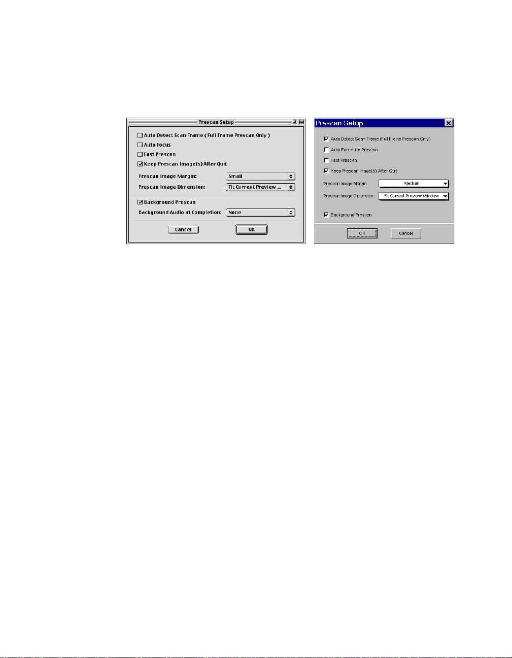
Prescan Setup
The Prescan Setup command lets you set your preferences on how ScanWizard
Pro TX should perform in carrying out prescans of your image. The parameters
you are allowed to control are described below.
(Macintosh) (Windows)
Auto Detect Scan Frame (Full Frame Prescan only)
If this box is checked, prescanning will be processed to detect the film frame
containing the image only (slide frame and film unexposed edges are ignored).
Note that this feature will work only if the Prescan button is set at “Full Frame”
mode before clicking the button.
Auto Focus (Mac)/Auto Focus for Prescan (PC)
If this box is checked, the prescan process will include the Auto Focus function
before the actual prescan is carried out. With Auto Focus, the prescanned image
will look clear and sharper. However, this may slow down the prescan process.
Fast Prescan
If this box is checked, the prescan process is accelerated, but the resulting image
is grainier (low resolution). If left unchecked, the resulting image will be of
better quality but the prescan process may slow down a bit.
Keep All Prescan Image(s) After Quit
If this box is checked, all prescanned images from the current session are
retained in the Preview window when you exit ScanWizard Pro TX. The images
will remain available in the Preview window the next time you launch the
program.
26 Microtek ScanWizard Pro TX for Mac & PC
Page 36

Prescan Image Margin
This option allows you to specify how wide or narrow the margin around the
scan frame is for the prescan image. Options are: Minimal, Small, Medium, and
Large. Smaller margins give you more room to capture the preview image, while
larger margins will allow you to have more room to expand your scan frame.
This is helpful when trying to select an exact scan frame (through the Scan
Frame tool) to scan. You can never select a completely accurate scan frame to
process. What appears to have been selected by the scan frame when you view
the image in the prescan view may or may not exactly appear as you wish it to
be. Some portion at the edges may be missing or emerge where you do not wish
them to be. The margin, depending on how wide or narrow it is can then provide
a berth or allowance for extending the boundaries of the scan frame around the
prescan image.
Prescan Image Dimension
This option lets you specify how large the prescan image will be: Full screen
(“screen” meaning your main monitor), 75% screen, 50% screen, and Fit
Preview Window. The larger the size, the higher the prescan resolution. The
maximum prescan resolution is the scanner's optical resolution.
Background Prescan
If checked, the background prescan function is enabled. You can assign a
number of scan jobs to execute a prescan while carrying out other jobs in the
meantime (e.g., performing color correction to other scan jobs). If unchecked,
this function is disabled.
Background Audio at Completion (Mac only)
This option allows you to enable audio and select a voice type to signal
completion of a prescan job.
Monitor Gamma Setup (PC only)
The Monitor Gamma Setup command lets you compensate for the linear
intensity of the monitor, making them consistent between pr eview image and the
final scanned image.
Adjust until the gray
level or shading of the 2
boxes are at equal
levels
Reference: The Preview Window 27
Page 37
Monitor Gamma
Check this box to enable monitor gamma value setting.
Click the up/down arrow to adjust the gray-level (shading) of the two boxes until
they are equal or they merge into a single shade level. Then click OK to apply.
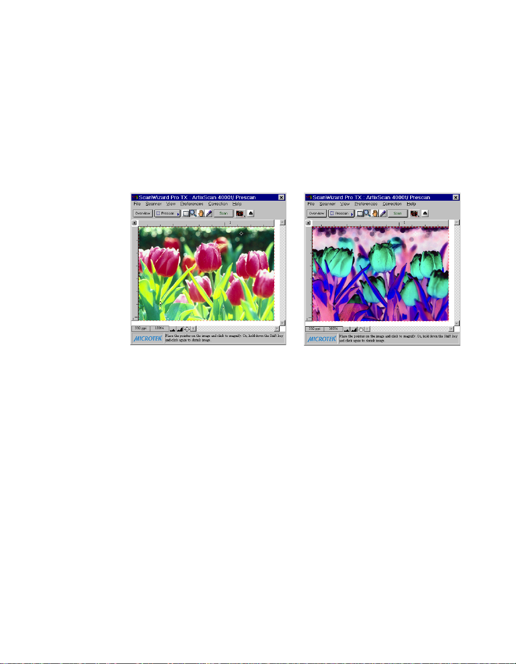
Invert
This command inverts or creates an effect similar to negative film for all scan
jobs.
T ake note that all scan jobs ar e inverted at the same time; you cannot invert an
individual scan job alone.
When an image is inverted, the brightness value of each pixel is converted to its
inverse value. In the case of 24-bit images, for example, a pixel in a positive
image with a value of 255 is changed to 0, and a pixel with a value of 5 is
changed to 250.
To use this feature:
Choose the Invert command in the Preferences menu. A check mark is shown
before the command when it is enabled.
28 Microtek ScanWizard Pro TX for Mac & PC
Inverted imageOriginal
Page 38

Retain Scan Module after Scan (Mac only)
This command allows you to keep the ScanWizard Pro TX interface running
after scanning is completed and the image delivered to your image-editing
software. This way, you do not have to go back to the File-Acquire process to
start ScanWizard Pro TX all over again.
::
NOTE
: This command can be used only in applications (such as Adobe Photoshop) that
::
allow you to retain the scan module after a scan is completed. Some applications will not
retain the scan module even if this option is enabled.
This command does not function when you run ScanWizard Pr o TX in Batch Mode or
through Applet.
To use this feature:
Choose the Retain Scan Module after Scan command in the Preferences menu. A
check mark is shown next to the command when it is enabled. If you wish to see
the scanned image in your image-editing software after scanning is completed,
you will need to quit ScanWizard Pro TX to see the image.
More
The More command shows the More Preferences dialog box, where you can
specify other options for ScanWizard Pro TX.
Options for APS
Film or 120 Film (6 x9
cm) supported
scanners,
depending on the
scanner you are
using
(Macintosh)
(Windows)
Options for APS Film or 120 Film (6 x 9 cm)
supported scanners, depending on the
scanner you are using
Reference: The Preview Window 29
Page 39

Keep Overview Image (PC only)
If checked, the overview images in the Job Panel window remain intact when
you exit from ScanWizard Pro TX and are automatically displayed in the next
scanning session. If unchecked, ScanWizard Pro TX deletes the overview images
when you exit the program.
Smoked Glass Background
When enabled (checked) this option will apply a smoked glass background to
the area outside the actual scan job (everything outside the scan frame), while
the actual scan job is highlighted. This makes your actual scan job stand out
from the rest of the image.
Selected scan job
(enclosed in the scan frame)
Smoked glass background
Warn if No Holder is Inserted
If checked, a warning message will display whenever you try to do an overview ,
prescan, or scan image with the film or slide holder not inserted or improperly
inserted into the scanner. If unchecked, the message does not appear.
30 Microtek ScanWizard Pro TX for Mac & PC
Page 40

Auto Focus for Final Scan
If this box is checked, the final scan process will include the Auto Focus function
before the actual scan is carried out. With Auto Focus, the final scan will look
clear and sharper. However, this may slow down the final scan process.
Auto Overview
If checked, your scanner automatically performs a full overview of all your
originals when ScanWizard Pro TX is launched, and shows the overview images
in the Job Panel window. If unchecked, Auto Preview is disabled. You need to
click the Overview button to execute an overview.
Working Color Space (Mac)/Color Space Mode (PC)
This option lets you choose between the default LCH color space or the Native
color space. If the LCH mode is selected, the color space is represented by
Lightness, Chroma (saturation), and Hue. If the Native mode is selected, color
enhancements are performed by RGB, CMYK or Lab.
Scan Quality
This option allows you to select image quality by controlling the scanner
hardware and the maximum image processing depth.
SpeedSpeed
Speed Choose this option if your primary concern during scanning is
SpeedSpeed
speed. Image data is delivered faster and the image data is processed in 8 bits per channel. This results in a lower-quality image.
QualityQuality
Quality This is the default setting. Scanned data is delivered a little slower
QualityQuality
but in high quality, and the image data is processed in 8 bits per
channel.
Best QualityBest Quality
Best Quality Scanned data is delivered a little slower but in high quality, and
Best QualityBest Quality
image data is processed in maximum bits per channel (i.e., 10-,
12-bit, or higher), and then converted to the desired output
depth.
If your scanner supports the Multiple Sampling feature, this
selection will also enable the Multiple Sampling options that will
allow you to scan image with the best possible quality.
Best Quality Multiple Sampling
This feature is available only if your scanner supports the Multiple Sampling
which allows your scanner to perform multiple scans on each line and then
converts their average into one line. This scheme reduces image noise while
increasing the dynamic range of the scanner.
Reference: The Preview Window 31
Page 41

Mac users
: :
NOTE
: The Best Quality Multiple Sampling pane is grayed if your scanner does not
: :
support the feature or your Scan Quality setting is not set at “Best Quality.”
With everything else are done except
for the final scan, set the Scan Quality
setting at “Best Quality” and click the
expansion arrow on the Best Quality
Multiple Sampling pane. From the
resulting drop-down menu, choose the
number of lines you wish to be
sampled when the scanner performs
final scanning. Available options are 2,
4, 8, and 16 lines. Choose None if
multiple sampling is not required.
PC users
: :
NOTE
: The Best Quality Multiple Sampling option will not appear if your scanner does
: :
not support the feature.
When you are ready for the final scan, click the expansion arrow on the Scan
Quality pane then drag pointer down the resulting menu till it highlights the Best
Quality (Multiple Sampling: None) option. Then choose the number of lines you
wish to be sampled when the scanner performs final scanning from the
secondary menu. Available options are 2, 4, 8, and 16 lines. Choose None if
multiple sampling is not required.
32 Microtek ScanWizard Pro TX for Mac & PC
Page 42

Interpolation Mode
Interpolation mode controls the way ScanWizard Pro TX interpolates (either
expands or shrinks) image data. Interpolation always occurs when the scan
resolution you select is different from the scanner's optical resolution. The
trade-off is speed (Nearest Neighbor) vs. quality (Bi-Linear).
The Speed option supports faster scanning at fair image quality; the Bi-Linear
(Quality) option produces fine image quality approaching Adobe Photoshop's bilinear interpolation function but entails longer scanning time.
Memory Usage (Mac only)
This option controls the way ScanWizar d Pro TX uses memory. Three options
are provided:
ApplicationApplication
•
Application: ScanWizard Pro TX will only use the memory inside the
ApplicationApplication
application heap as its image buffer. Make sure you allocate a large amount
of memory in your application for this purpose. Otherwise, ScanWizard Pro
TX may not have enough memory to run. Use this option only if you do not
want ScanWizard Pro TX to use memory outside your application.
SystemSystem
•
System: ScanWizard Pro TX will use the memory in the system heap as its
SystemSystem
image buffer , and only a limited amount of memory is used in the application
heap. This option is best if you have only a small memory allocation for your
application but a large amount of system memory.
AutoAuto
•
Auto: This is the default setting. ScanWizard Pro TX maximizes the memory
AutoAuto
usage from both system and application, looking for memory first from the
system heap and then from the application heap.
Default Orientation
This option allows you to specify the default display orientation or the rotation
of images for each type of scan material (slide, filmstrip, APS film, or 120 film )
when Overview, Prescan or Scan is performed. Notice that option APS film and
120 film are exclusive, depending on the scanner you are using. Options of
orientation are:
90° clockwise90° clockwise
•
90° clockwise
90° clockwise90° clockwise
90° counterclockwise90° counterclockwise
•
90° counterclockwise; default
90° counterclockwise90° counterclockwise
None None
•
None (displays image as seen on holder held in upright position)
None None
Note that the new default setting will take effect only after restarting
Reference: The Preview Window 33
Page 43

ScanWizard Pr o TX. You can always change the rotation anytime during the
scanning session by clicking on the T ransform icon in the Settings window.
Scratch Directory (Mac only)
The Scratch Directory is the buffer folder where ScanWizard Pro TX creates and
holds temporary image data file while overviewing, prescanning, and scanning
images. The scratch file is needed only until the current scan ends or
ScanWizard Pro TX is terminated. The file is then deleted.
You should change to a different folder only if the default scratch directory
(where your current ScanWizard Pro TX is located) is located in a disk with
limited space to accommodate scanning operations. To specify a new scratch
directory, choose Other Directory... from the option list.
Thumbnail Size (PC only)
This option allows you to choose between two sizes of thumbnail display in the
Job Panel window during Overview . Sizes available ar e 96 x 96 pixel (default)
and 128 x 128 pixel.
The Correction Menu
The Correction Menu is an alternative way to access the Advanced Image
Correction (AIC) tools normally available from the Settings window. Note that
corresponding short-cut keys for each tool are also provided in the above menu.
See the section on the Settings window of this manual for the detailed
information of each AIC tool.
34 Microtek ScanWizard Pro TX for Mac & PC
WindowsMacintosh
Page 44

The Help Menu
WindowsMacintosh
The Help menu lets you access on-line help for ScanWizard Pro TX and the
Microtek web site. The contents of this menu may vary and will depend on your
scanner package.
Reference: The Preview Window 35
Page 45
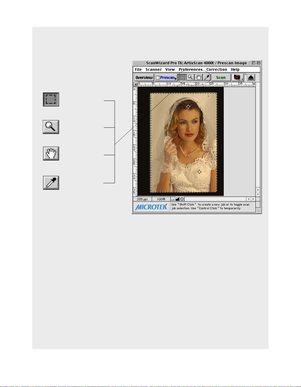
The Toolbar
Scan Frame
Zoom
Pane
Tag Windows
36 Microtek ScanWizard Pro TX for Mac & PC
Page 46
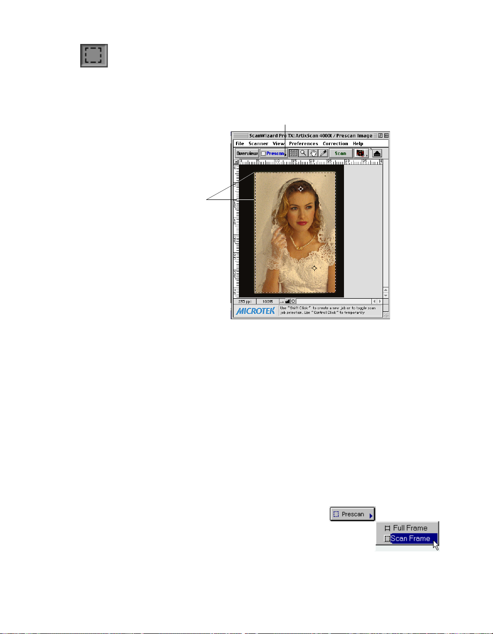
Scan Frame tool
The Scan Frame tool lets you select an area from the prescan image for another
prescan or a final scan. You can only create one scan frame at a time. When a
new scan frame is created, the previous one is deleted.
Click arrow for prescan frame options
Drag corner or border
to resize scan frame
Creating a Scan Frame on thumbnail overview image for prescanning
1. If a blank scan frame does not appear in the Preview window (i.e., no image
appears in it), click the Scan Frame tool.
2. From the Job Panel window, click the thumbnail image you want to scan.
Observe that the scan frame from the Preview window is now reproduced in
the selected Job Panel thumbnail image in miniaturized format. Any
adjustment of the scan frame from the Preview window will be
proportionally reflected in the corresponding Job Panel thumbnail scan
frame.
3. To resize the scan frame, drag its corner or border to the desired size. To
move the whole scan frame position, click and hold anywhere inside the scan
frame and move the whole scan frame to a new location.
4. To prescan the selected area only (enclosed by
the scan frame) delete from the thumbnail, you
must choose the “Scan Frame” option of the
Prescan button as shown in the figure at the right. Click
the list box arrowhead in the Prescan button to display
the options.
Reference: The Preview Window 37
Page 47

Adjusting Scan Frame on prescan image for final scan
1. The prescan image is pasted on the Preview window with its defined scan
frame intact. Thus, there is no need to click the Scan Frame tool again. Y ou
may, however, resize your scan frame to refine your selection.
2. To resize the scan frame, drag its corner or border to the desired size. To
move the whole scan frame position, click and hold anywhere inside the scan
frame and move the whole scan frame to a new location on the prescan
image.
Observe that the adjustment made of the scan frame from the Preview
window will be proportionally reflected in the corresponding thumbnail scan
frame in the Job Panel window.
38 Microtek ScanWizard Pro TX for Mac & PC
Page 48

Zoom tool
The Zoom tool lets you zoom in (magnify) and zoom out (shrink) your view of
the image. Only your view of the preview image is changed; the actual size of the
image remains unaffected.
Each click of the zoom tool (magnifying glass) pointer magnifies or reduces the
image display by a factor of 2. Thus, the magnification level increases from 100%
to 200%, to 400%, and to 800% (to the maximum 1600% for Mac) and
decreases at opposite decrements.
Zoom tool
Original image view Zoom in Image view
T o use the Zoom tool:
1. Click the Zoom tool and point to the image. Observe the pointer turning into
a magnifying glass with a plus (+) in it.
2. Click the plus (+) pointer on the image. The image is magnified at each click.
3. T o zoom out (shrink image display), hold down the Option key (for Mac)/
Shift key (for PC) with the pointer on the image. (Observe the plus (+) sign in
the pointer changing to minus sign (-) to indicate that the zoom out action is
ready.) Then click to shrink your view of the image. The image display can
only be reduced to a size no smaller than the original view.
Reference: The Preview Window 39
Page 49

Pane tool
The Pane tool lets you pan or drag out the hidden portion of a zoomed prescan
image into view . This is a faster way of viewing hidden image portions than using
the scroll bars.
Pane tool
Zoomed-in image partially on view
To use the Pane tool:
1. Click on the Pane tool and point to the image. Observe the pointer turning
into a hand pointer.
2. Click and hold on the image, then drag out the hidden portion of the image
you want to view .
40 Microtek ScanWizard Pro TX for Mac & PC
Right section of the hidden portion drag into
view with Pane tool
Page 50
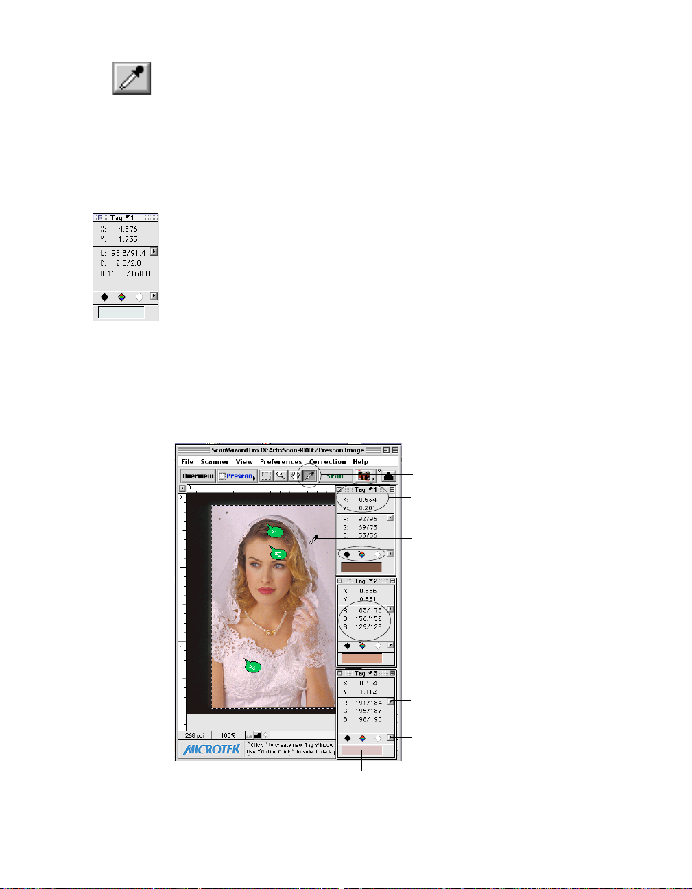
Dropper tool
The Dropper tool is actually a 3-in-1 tool. It consists of the T ag W indows tool,
Black Eyedropper tool and White Eyedropper tool. The Tag Windows tool
provides pixel information at the pointer position on the prescan image. With
the pixel information, the T ag Windows tool allows you to further adjust the
Black (shadow) point, White (highlight) point, and color cast (LCH mode only)
directly on the image (instead of making the adjustments from the AIC tools in
the Settings window).
The T ag Windows tool also helps isolate and identify pr ecise colors in a given
image, providing a visible and retrievable record of color values. This way,
ScanWizard Pro TX lets you pinpoint and “tag” the color on the image, showing
you the original or “Before” values, as well as the corrected or “After” values
following the application of image adjustment controls.
This tool is particularly useful in performing color adjustments based on known
mathematical values, as the displayed color information provides a base in
determining how close or accurate are the color changes that have been made.
Tag marker at selected color where Tag Windows
dropper (with “ T” ) pointer is clicked and where the
corresponding Tag window is created
Color Strip showing the
selected or adjusted color
Dropper tool
x, y coordinates of Tag Window #1
White Eyedropper tool
Magic Diamonds (L-R black, color cast,
and white diamonds)
RGB values of the selected White or
Black reference point (where
Dropper pointer is clicked)
“ Before” value (left side of slash)
“ After” value (right side of slash)
Color space mode (LCH or Native)
selection
Reset (White/Black Points or Color
Cast setting) selection
Reference: The Preview Window 41
Page 51

Actual adjustment of the selected image color can be accomplished through the
Magic Diamonds feature in the tag windows. For Highlight and shadow
corrections, the same task can also be done by the Black & White Eyedropper
tools. Adjustments made by either the Eyedroppers or Magic Diamonds are
simultaneously reflected in the AIC's W&B Points and Color Cast dialog boxes.
The Tag Window tool
Black Magic Diamond
Color Cast Magic Diamond
White Magic Diamond
To cr eate a tag window
Click the T ag W indows tool, then move to the selected area of the image wher e
you want to adjust highlight, shadow, or color cast of the prescan image (observe
the pointer turning into into an eyedropper with a “T”). Then click. A tag
window is immediately created together with a tag number marker (marking the
selected spot).
To close tag window(s)
For Mac
T o close individual tag windows, click the Close box on the top-left corner of the
tag window .
T o close all tag windows simultaneously, hold down the Option key, then click the
Close box of any tag window.
For PC
T o close individual tag windows, click the Close box on the top-right corner of
the tag window .
T o close all tag windows simultaneously, hold down the Shift key, then click the
Close box of any of the tag window.
42 Microtek ScanWizard Pro TX for Mac & PC
Page 52

Adjusting shadow & highlight with Magic Diamonds
• To set the shadow (black) point on the prescan image, click the Dropper tool
from the Toolbar, then click on the selected black point in the image. When
the T ag Windows tool appears, click the Black Magic Diamond.
• To set the highlight (white) point on the prescan image, click the Dropper
tool from the Toolbar, then click on the selected white point in the image.
When the T ag Windows tool appears, click the White Magic Diamond.
NOTE
: V alues of the black and white points should not overlap (i.e., black value
should not exceed White value; White value should not be less than that of Black.
Otherwise, an error message will display .
Adjusting color cast with Magic Diamonds (LCH mode only)
• To add a color cast, click the Dropper tool in the T oolbar, then click on the
selected color in the image that corresponds to the color cast you want to
add. Hold down the Option key (Mac)/Alt key (PC). Notice that the default
minus sign (-) of the Color Cast Magic Diamond turns into a plus (+). Then
click the “plus” Color Cast Magic Diamond to apply the selected color cast.
• To remove a color cast, click the Tag W indows tool in the Toolbar, then click
a color in the image that corresponds to the color cast to be removed. From
the tag window, click the “minus” Magic Diamond to remove the unwanted
color cast.
NOTE
: Adding or removing a color cast from an image is always based on the original
image. If you attempt to add and/or remove a color cast mor e than once, only the last
addition or removal will take effect.
The White & Black Eyedropper tool
•
White Eyedropper tool Black Eyedropper tool
To create the White and Black Eyedropper tool
• If you are not in Dropper tool mode yet and want to create the White
Eyedropper tool, click on the Dropper tool from the Tool bar while pressing
the Apple Command key (Mac)/Shift key (PC). Observe the pointer turning
into the White Eyedropper tool. If you are already in Dropper mode, just
press the combination keys.
• To create the Black Eyedropper tool, repeat the procedure above but press
the Option key (Mac)/Ctrl key (PC) combination keys instead.
Reference: The Preview Window 43
Page 53

Adjusting shadow & highlight with White & Black Eyedropper tools
• T o adjust the highlight (white point) in an image, point the White Eyedropper
tool to the selected white point in the image. Then click to apply the selected
lightness.
• T o adjust the shadow (black point) in an image, point the Black Eyedr opper
tool to the selected black point in the image. Then click to apply the selected
shadow value.
NOTE
: V alues of the black and white points should not overlap; i.e., black value should
not exceeds White value; White value should not be less than that of Black. Otherwise, an
error message will display.
Color information preview in pixel
While making adjustments with the T ag Windows or Eyedr opper tools, you can
view and refer to the Color Display in the Information window where the pixel
input/output values of the selected spot (where your pointer is pointed on the
image) is shown. Aside from pixel values, the Information window also provides
a live graphic preview of a pixel-by-pixel breakdown of the selected area. This
will allow you to pinpoint the exact color pixel you want to adjust. Y ou can
adjust the size of the sample box of the preview to focus on a certain number of
pixels.
For more details, refer to the Information Window section of the manual.
Color Meter Display for LCH
Pixel graphic preview
with a sample box
focusing on 3x3 pixels
44 Microtek ScanWizard Pro TX for Mac & PC
Color Meter/pixel
sample preview size
Options button
Page 54

T o restore original settings
To cancel made by the Dropper tools to the prescan image and restore settings
to the original, click on the “Reset” button (adjacent to the Magic Diamonds).
When the Reset option list displays, choose which adjustments (White/Black
Points or Color Cast) you want to restore.
Reset White/Black Points
or Color Cast settings
Alternatively, you can restore settings to their original using the Reset options at
the bottom of the Settings window .
Reference: The Preview Window 45
Page 55
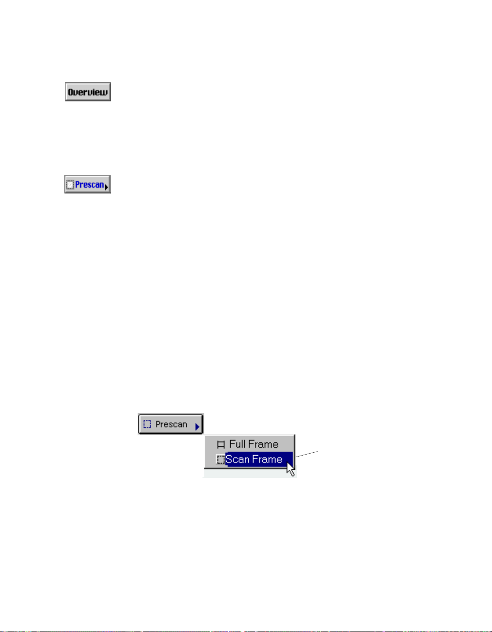
Overview, Prescan, Scan
Overview button
The Overview button previews all the slide or negative film images from your
scanner. The entire film holder is previewed when you click the Overview button
and displayed on the Job Panel window in thumbnail size. Thumbnail image size
can be set to 96 x 96 pixels or 128 x 128 pixels depending on the setting
specified in the More Preferences command under the Preferences menu.
Prescan button
The Prescan button previews in high resolution a particular slide or negative film
image selected from the Overview images. Multiple prescans can be done if you
have several selected scan jobs.
T o obtain multiple prescan images:
1. Select your scan jobs in the Job Panel window (see the Job Panel window
section for more details).
2. T o select multiple scan jobs randomly, press the Shift key (Mac) / Ctrl key (PC)
and click on the thumbnails of your choice.
To select all scan jobs, click on the Select All button in the Toolbar of the Job
Panel window .
3. Then click the Prescan button to start the multiple prescanning process of
selected images into the Preview window.
To preview a particular prescan from the Preview window, click the
corresponding image on the Job Panel window.
Frame prescanning or prescan the area enclosed by the scan frame only. To
choose, click on the arrowhead in the Prescan button to display option.
The selected Scan Frame setting is applicable towards the final scan.
46 Microtek ScanWizard Pro TX for Mac & PC
Prescan frame size
option
Page 56

Scan button
The Scan button scans the images on your scanner and delivers the images to
your image-editing software or files. Only those images that have been checked
in the Job Panel window are scanned.
By default all default originals are checked for scanning. However, empty frames
in a slide or filmstrip holder are not included.
::
NOTE
:
::
For Mac Users:For Mac Users:
For Mac Users: I f the
For Mac Users:For Mac Users:
is checked, you need to exit ScanWizard Pr o TX to see the scanned image in your imageediting software.
For PC Users:For PC Users:
For PC Users: You need not exit fr om ScanWizar d Pro TX if you only want to see the
For PC Users:For PC Users:
display of the scanned image in your image-editing software. However, you need to exit
ScanWizard Pr o TX if you need to edit the image with your image-editing software.
Retain Scan Module After ScanRetain Scan Module After Scan
Retain Scan Module After Scan option (in the Pr eferences menu)
Retain Scan Module After ScanRetain Scan Module After Scan
Reference: The Preview Window 47
Page 57

Rulers, Unit of Measurement
The rulers on the top and left sides of the Preview window help you with
measurement and alignment, marking off measurement according to the
selected unit (inch, pica, pixel, etc.).
The unit of measurement can be selected in two ways:
• Through the Unit List box in the Settings window.
• Through the arrowhead at the corner where the vertical and horizontal
rulers meet in the Preview window .
The drop-down menu through this method also lets you format the
colorcolor
color an d
colorcolor
The options for unit of measurement include inch, centimeter , millimeter , point,
pica, and pixel. The pixel option is dimmed if the selected resolution unit is lpi.
Note that any change in the ruler's unit of measrement is similarly reflected in
the unit of measurement for the edit boxes in the output image dimensions in
the Settings window .
background colorbackground color
background color o f your rulers (Mac only).
background colorbackground color
Select the unit of measurement for the rulers either from
the Settings window or the Preview window.
texttext
text
texttext
48 Microtek ScanWizard Pro TX for Mac & PC
Page 58

Preview Area
The preview area is where the prescan image appears. You can zoom in the size
of the preview area to see more details of your image.
T ake note of the following:
• When you perform an overview, the overview images are displayed in the Job
• When you perform a prescan, the prescan image is displayed in the Preview
Panel window in thumbnail size.
window. Its detail is determined by the settings in the Prescan Setup dialog
box.
Use these buttons (the Magnifying
Glass tool) to zoom in and zoom out
the image on preview
Preview area
To increase the
preview area,
just drag out this
corner
Reference: The Preview Window 49
Page 59

Auxiliary information and Handy buttons
Current prescan
image resolution
Zoom in/out
scale status
Zoom out
Toggle for momentary
flashing of White & Black
Markers
Zoom in
Tips on Toolbar tool
currently in use
Prescan image resolution
This shows the image resolution for the current Prescan image. The resolution
will change when the size of the Preview window changes at the next prescan.
T o resize the preview window, drag any side or corner of the window.
Zoom in/out scale
This shows the zoom scale factor (in %) with which the image has been
magnified or shrunk while using the Zoom in or Zoom out icon.
Zoom-in
Magnifies image display by a factor of 2. Thus, the magnification level increases
from 100% to 200%, to 400%, and to 800% (to the maximum 1600% for Mac).
Zoom-out
Decreases image magnification one level down at each click till the original size
(100%) is reached.
Toggle for momentary flashing of White and Black Markers
When the prescan image is displayed, the White marker (showing the highlight
point of the image) and Black marker (showing the shadow point of the image)
are shown. When you have difficulty locating the markers from the image,
clicking on the Flasher icon will make the markers flash for a few seconds to
catch your attention.
50 Microtek ScanWizard Pro TX for Mac & PC
Page 60

The Settings Window
The Settings window contains the parameters for outputting your scanned image
for the current scan job and includes the advanced image correction tools of the
program.
Elements of the Settings window
D. Scan Frame, Scaling,
and Output settings
A. Current scan job
B. Scan job image type
C. Resolution/unit settings
E. Image memory size
F. Scan Frame
options
J. Image preset
adjustments
K. Advanced Image
Correction (AIC) tools
for LCH mode
G. Unit of measurement
H. Transform (rotate/flip
preview image)
I. Scanner Profile for slides
(Changes to Film Type when
scan material is negative
film)
L. AIC Custom options
M. AIC reset button
Reference: The Settings Window 51
Page 61

A. Job
This shows the current scan job as selected in the Job Panel window and
displayed in the Preview window.
B. Type
This shows the image type of the current scan job.
C. Resolution settings
This area includes the following
::
: the Resolution box for specifying your output
::
resolution; the Resolution list box (with the up/down arrows) that provides
predefined resolution values for easier selection of the resolution setting; and
the Resolution unit, which lets you choose fr om ppi and several lpi options. Y our
most recent scan resolution settings will be recorded as well.
D. Scan Frame settings, Scaling, and Output settings
This area includes the following
::
: the Scan Frame settings (including the Scan
::
Frame width and height edit boxes), which represent the dimensions of the area
on the film that you wish to scan; the Scaling factor for creating larger or smaller
images from the original source image; and the Output settings (including the
Output width and height edit boxes), which represent the dimensions of the
image when it is output after the final scan. Pressing the small arrows
underneath the Scan Frame, Scaling, and Output fields will reveal a set of
predefined values for those fields.
E. Image size
This shows the memory size of the image file after the image is scanned. The
resulting file size is influenced by the defined image type (color , grayscale, etc.);
resolution; and dimensions for the output image.
F. Scan Frame options
These options set the behavior of the Scan Frame when prescanning an image.
The options are Fixed Scan Frame (where scan frame size remains constant for
every prescan and scan), Fixed Output Size (where the output dimension
remains constant regardless of scan frame size), and Keep Proportion (where
scan frame width changes proportionally when its height is changed, and vice
versa).
G. Unit of measurement
This lets you choose your desired unit of measurement, which will then be
reflected in the rulers alongside the Preview window. Choose from inch, cm, mm,
point, pica, or pixel.
52 Microtek ScanWizard Pro TX for Mac & PC
Page 62

H. Transform
This lets you rotate the preview image at increments of 90° and flip vertically or
horizontally to achieve a mirror effect.
I. Scanner Profile
This lets you select different ICC scanner profiles for your scan job.
J. Image Category
select predefined adjustments for a specific type of image matching your
original. (e.g., sunsets featuring predominant red and orange hues; portraits with
a preponderance of skin tones, etc.). The image category thus provides a starting
point for optimizing your image.
K. Advanced Image Correction (AIC)
The AIC tools let you adjust and enhance the image with a real-time preview of
the effect applied. The AIC tools available for use will vary, depending on the
color space (LCH or Native mode) chosen in the “More” command (see
Preferences menu of the Preview window).
L. Custom options
These allow you to choose one of the following options for the pertinent AIC
control:
• Select an existing custom settings (if any)
• Create and add a new custom settings
• Revert to the “no correction” status
M. Reset button
This changes settings in all or selected AIC controls to their default values.
Reference: The Settings Window 53
Page 63

Job
The Job box shows the currently selected scan job (as the highlighted image in
the Job Panel window and on preview in the Preview window).
There is always at least one scan job in existence (default); all entries (with or
without image) in the film holder are always treated as multiple entries in the Job
Panel window. These entries are similarly shown as multiple entries in the Job
box list of the Settings window. Selecting a frame as a scan job may be done from
either the Job box list or Job Panel window and the selected scan job is always
reflected in both places. If the selected scan job has previously been prescanned,
the pertinent prescan image will display in the Preview window as well.
This means that a quick look at the Job box, the Preview Window, or the Job
Panel window, will show you your current selected scan job.
The current scan job will
always appear in the Settings
window and Job Panel
window. If prescanned, it will
also display in the Preview
window
54 Microtek ScanWizard Pro TX for Mac & PC
Page 64

Type
ScanWizard Pro TX allows direct scanning of your
original into the following color spaces described
below. The desired color space for your output can
be selected from the Type list box of the Settings
window.
RGB
RGB (Red, Green, and Blue) images use three colors
to reproduce up to 68.7 billion colors. Because
scanners and monitors are RGB devices, the RGB
color space is the most commonly used color space for capturing and displaying
images. ScanWizard Pro TX offers standard RGB and 48-bit RGB color selection,
with the 48-bit option available for the Artix line of scanners and other Microtek
professional pre-press scanners.
Grayscale
Grayscale images use shades of gray to simulate gradations of color or tonal
values, and contain 8 bits per pixel. The Grayscale 16-bit option is provided in
ScanWizard Pro TX for professional pre-press scanners.
CMYK
CMYK images are made up of the standard four colors (cyan, magenta, yellow
and black or K) for separated film or digital files used for sheetfed or web offset
printing. CMYK mode instantly converts the scanner’s RGB input to the CMYK
color space. CMYK images are four -channel images, containing 32 bits per pixel.
Lab Color
Lab images are three-channel images containing 24 bits per pixel. Lab mode is
useful for editing a pixel’s luminance but not its color values. Lab mode produces
device-independent color and is recommended for moving images between
systems or printing to a PostScript Level 2 printer.
Reference: The Settings Window 55
Page 65
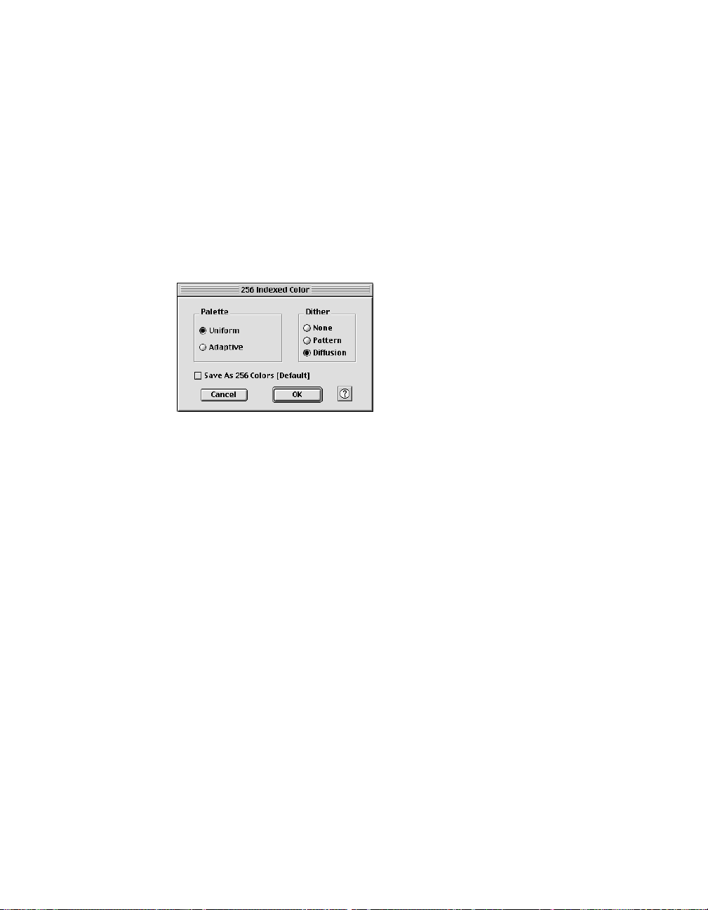
Web / Internet Colors
This mode is useful for displaying images on the W eb or Internet. Output for the
W eb / Internet color mode in ScanW izar d Pro TX is 8-bit, 256 indexed color
images in the sRGB color space.
256 Colors (Default) / 256 Colors (Custom)
These are single-channel images (8 bits per pixel) that use a color lookup table
containing up to 256 colors. The file size is smaller for images in this mode. As
an initial setting, selecting 256 Colors (Default) uses an Adaptive palette with
Diffusion. If the 256 Colors (Custom) option is selected, the dialog box below
appears.
Palette:Palette:
1)
Palette: The Palette option lets you
Palette:Palette:
choose the method for creating the color
palette table. Uniform uses a 6-6-6 fixed
color palette table. Adaptive (default)
creates a color palette table from the
more commonly used areas of the color
spectrum that appears in the image.
Dither: Dither:
2)
Dither: The Dither option can improve the color quality of the 256-indexed
Dither: Dither:
color image for photographs or continuous-tone images, using a technique of
mixing available colors to simulate missing colors. None provides no dithering.
Pattern uses a structured pattern to simulate missing colors. Diffusion (default)
uses the error diffusion technique to dither colors and produces the best quality
for 256 colors.
Line art
Line Art images are made up of one bit of color (black or white) per pixel. Few
editing options are available in this mode, but this mode is useful for images
consisting purely of black and white or even single colors, such as mechanical
drawings, blueprints, or fine-line illustrations.
Black-and-White Diffusion
This is a single-bit black-and-white image dithered with error diffusion. The
black and white pixels are arranged in a way as to “fool” the eye into seeing gray.
56 Microtek ScanWizard Pro TX for Mac & PC
Page 66

Resolution settings
The settings related to resolution include the resolution box, the resolution list
box, and the resolution unit.
Resolution is the sampling of image pixels per measurement unit or the amount
of pixel information stored in an image. T ogether, the image resolution and
dimensions determine the file size of the image, which is measured in kilobytes
(KB) or megabytes (MB).
The resolution of an image is important in determining the quality of the output
image. Resolution is also directly related to file size, and the higher the
resolution, the larger the resulting file size will be.
When dealing with resolution, remember to distinguish between optical
resolution and interpolated resolution.
Optical resolution is the “real” resolution as measured by the scanner's optics.
Interpolated resolution is software-enhanced resolution and can be useful for
enlarging very small images or for printing line art to obtain superior results.
A. Resolution list box
This shows the resolution setting. To set your resolution:
Enter a resolution setting in the Resolution edit box, then press Enter . If the
value you enter is too low or too high, the minimum or maximum resolution
value is entered for you instead.
According to the image type you select, the default resolution is displayed. When
you specify the resolution you need, this value is recorded for subsequent use.
ScanWizard Pro TX records last 6 different resolution settings.
Reference: The Settings Window 57
Page 67

B. Resolution unit
The unit of measurement for resolution is in ppi (pixels
per inch) or lpi (lines per inch). Take note that lpi
settings are dimmed if the ruler unit is in pixels.
To select your resolution unit:
• Choose ppi if your scanned images are intended for
on-screen display. In this case, you need not go higher than the target
resolution of your monitor (usually 72 dpi for Macintosh and 96 dpi for
Windows). A higher resolution value will simply increase the file size of your
image without any perceptible improvement in image quality.
• Choose lpi if your scanned images are to be printed. If you choose 1x, for
instance, your scanned image will be printed at 133 lines per inch, resulting
in a 133-dpi image. At 1.5x, the image will be printed at 199.5 dpi; and at 2x,
the image will be printed at 266 dpi. The Custom option allows you to set an
lpi value of your own specification.
In choosing an appropriate lpi value, keep in mind that if the resolution is too
low, the image becomes pixelated, resulting in a deterioration of image
quality. (Pixelization is the process in which the Postcript language uses a
single pixel's color values to create more than one halftone dot.) Conversely,
if the resolution is too high, the file size becomes unwieldy, and your file ends
up containing more information than the printer needs, slowing down the
file transfer and the printing process.
58 Microtek ScanWizard Pro TX for Mac & PC
Page 68
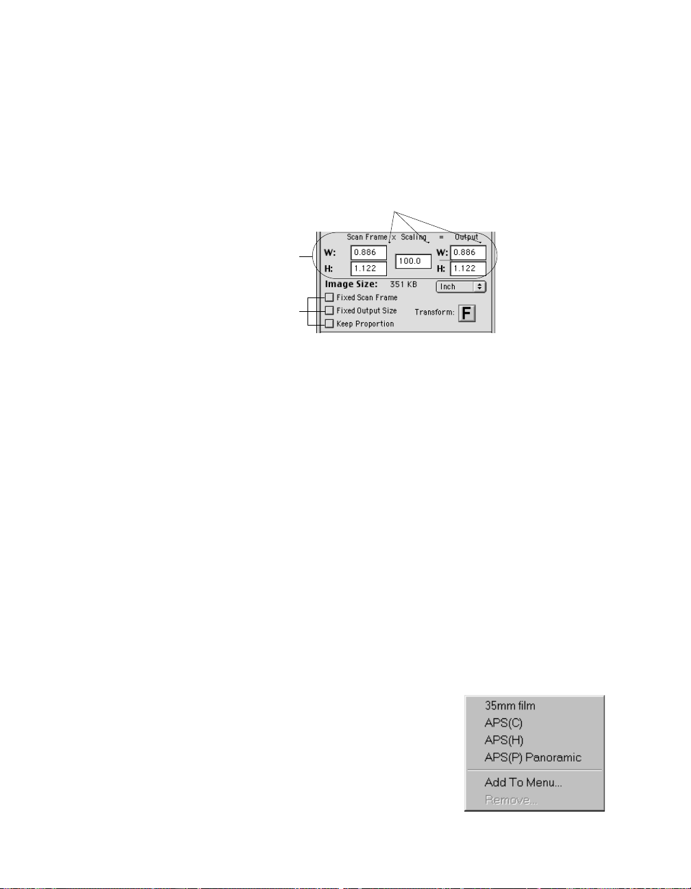
Scan Frame and related settings
These settings allow you to adjust the various factors that affect your image,
including the width and height of your image when it is first scanned (Scan
Frame setting), the Scaling factor (how big or how small the resulting scanned
image will be), and the dimensions of the image when it is output (Output
setting).
Click on arrow to display corresponding list
boxes of preset options
Output image
dimension
parameters setup
Scan Frame dimension
automation setup options
The Scan Frame settings, Scaling, and Output Settings work closely with the
three Scan Frame options (see check boxes below the “image Size” field).
In the default settings of ScanWizard Pro TX, where none of the Scan Frame
options are checked, take note of the following:
• Changing the Scan Frame settings (width or height) will change the Output
settings (width or height).
• Changing the Scaling will change the Output settings (width AND height).
• Changing the Output settings (width or height) will change the Scan Frame
settings (width or height).
Scan Frame settings
The Scan Frame settings (width and height) represent the area on the scan bed
that you wish to scan.
T o specify your settings, enter the dimensions manually in the width and height
edit boxes; or use the Scan Frame tool to define or resize your scan frame.
Changes made in the Preview window are automatically displayed in the Scan
Frame setting edit boxes.
If you wish, you can also choose from a menu of
predefined Scan Frame settings. To do this, click
on the arrow after “Scan Frame” (the first element
of the output equation in the Settings window),
and choose the setting window, then choose the
setting you wish from the menu that appears.
Reference: The Settings Window 59
Page 69

Add to menu/Remove:Add to menu/Remove:
Add to menu/Remove: If you wish to save the current Scan Frame setting as a
Add to menu/Remove:Add to menu/Remove:
frequently used dimension in subsequent scans, click “Add” to save and add the
setting to the menu after designating it with a reference name. You can delete the
customize setting by clicking on “Remove.”
Scaling Setting
Scaling lets you create larger or smaller images from the original source image.
T ake note of the following:
• Keep the scaling at 100% if you are outputting at the same size (e.g., a 35mm
original to be output at the same size).
• Reduce the scaling if you are outputting
your image at a smaller size (e.g., a 35mm
original to be output to 17.5mm). Increase
the scaling if outputting at a larger size.
To choose the scaling percentage, click the
up/down arrow next to the scaling box, or
enter a value in the scaling edit box.
If you wish, you can also choose from a menu
of predefined Scaling settings. To do this, click
on the arrow after “Scaling” (the second
element of the output equation in the Settings
window), and Settings window , then choose
the setting you wish from the menu that
appears.
• Film scale mapping: Choose your image
material and the output dimension. For example, 35mm to 5” x 7” means
your image source is 35mm film, and output size is 5" x 7".
Add to menu / Remove:Add to menu / Remove:
•
Add to menu / Remove: If you wish to save the current Scaling setting for
Add to menu / Remove:Add to menu / Remove:
subsequent scans, click “Add” to save and add it to the menu after designat-
ing it with a reference name. You can delete the customized Scaling setting by
clicking on “Remove.”
Scaling is also affected by your resolution setting. When you change resolution
and specify a value that has no exact equivalent for scaling, the scaling may be
affected and adjusts itself to the nearest allowed value. For instance, if your
resolution is 100, your scaling becomes 99 (instead of a full 100), because that is
the closest scaling equivalent, given the resolution value.
60 Microtek ScanWizard Pro TX for Mac & PC
Page 70
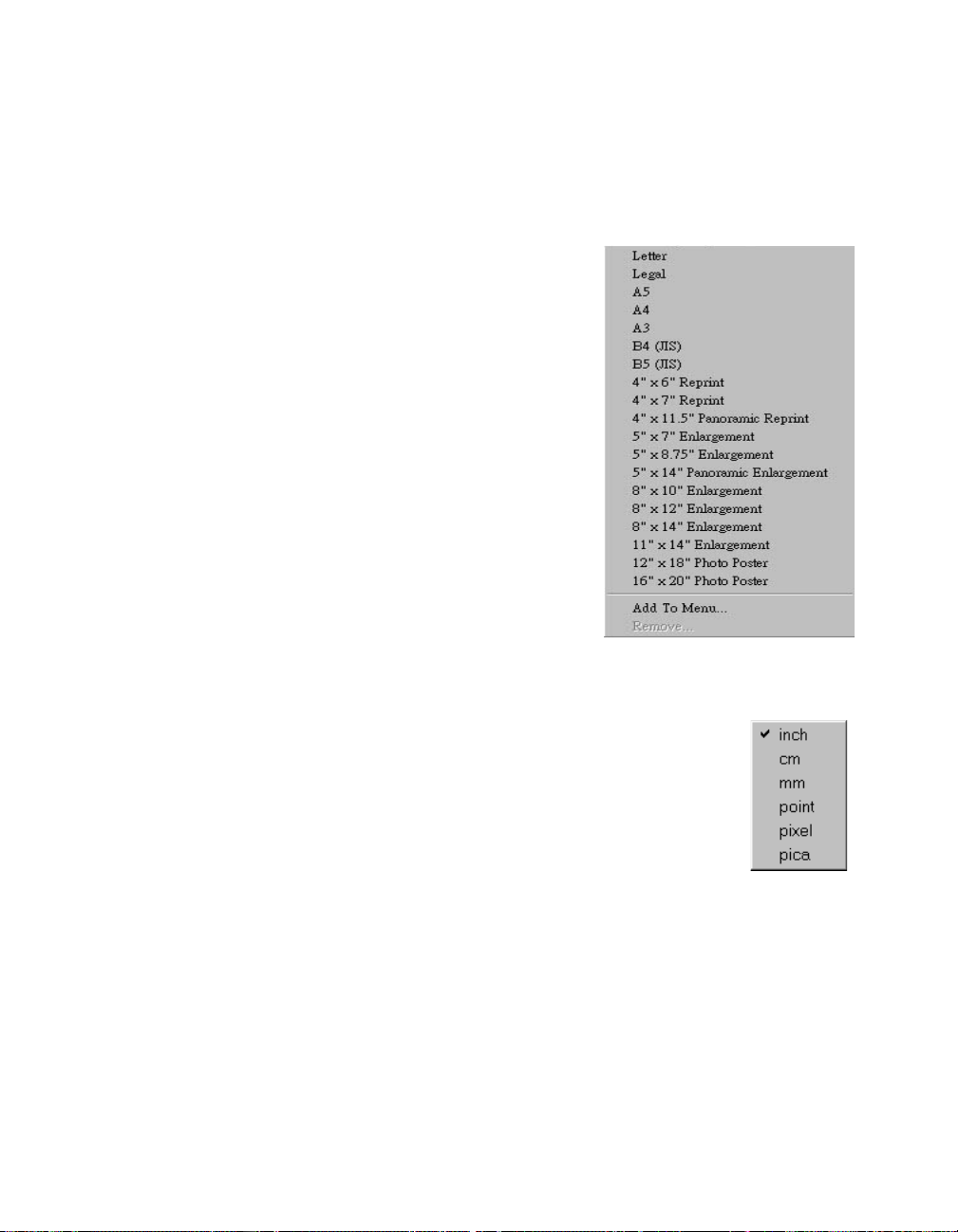
Output settings
The Output settings (width and height) represent the dimensions of the image
when it is output (to either monitor or printer). If the size of the image to be
output is different from the size of the original source image, adjust the scaling
percentage, or manually increase / decrease the output values accordingly.
If you wish, you can also choose from a
menu of predefined Scaling settings. To do
this, click the arrow after “Output” (the
second element of the output equation in
the Settings window), and choose the setting
you wish from the menu that appears.
Add to menu / Remove:Add to menu / Remove:
Add to menu / Remove: I f you wish to save
Add to menu / Remove:Add to menu / Remove:
the current Output setting as a frequently
used dimension in subsequent scans, click
“Add” to save and add the setting to the
menu after designating it with a reference
name. You can delete the customized setting
by clicking on “Remove.”
Image Size
The Image Size field indicates how big the
file will be when you accept the dimensions
shown in the edit boxes, together with the resolution setting that you have
selected. Size is calculated automatically.
Unit of Measurement
The Unit of Measurement lets you select the desired unit (inch,
cm, mm, point, pica, pixel) for your image dimensions. This will
also affect the ruler measurement in the Preview window.
IMPORTANT
before you enter any of the values for width or height in the Scan Frame Settings or
Output Settings.
::
: Make sure you select the correct unit of measur ement
::
Reference: The Settings Window 61
Page 71

Scan Frame options
The Scan Frame options include Fixed
Scan Frame, Fixed Output Size, and Keep
Proportion.
Fixed Scan Frame
This option lets you lock in the settings of your scan frame, so that the width and
height dimensions of the frame are always preserved no matter where you move
the frame in your preview image.
If you know the exact input size for your image, or if you wish to “lock” the
settings of your scan frame to a particular size, enter the Scan Frame width and
height values first, then check Fixed Scan Frame. Your scan frame will be “fixed”
at those values, so even if you move the scan frame around the preview image,
the dimensions of the frame itself will remain unchanged.
Fixed Output Size
When the Fixed Output Size option is checked, the values specified for output
width and height remain unchanged. If any of the input values are changed, the
scaling will be adjusted automatically to preserve the output dimensions
correctly.
If you know the exact output size for your image, enter the output width and
height values first, then check Fixed Output Size. The image will then be scanned
and output at the values you specify.
Keep Proportion
When the Keep Proportion option is checked, the width and height values of the
image are kept in proportion regardless of changes made to either setting. This
preserves the aspect ratio of the image.
This option is automatically checked when either “Fixed Scan Frame” or “Fixed
Output Size” is selected.
::
NOTES
:
::
• When none of the Scan Frame options are checked, all five dimension edit boxes ar e
enabled; i.e., you are allowed to edit or enter values into any of the boxes.
Fixed Scan Frame Fixed Scan Frame
• The
Fixed Scan Frame and
Fixed Scan Frame Fixed Scan Frame
one of the options can be checked at a time; checking one option will automatically
uncheck the other.
• When an illegal value is entered (e.g., the input width exceeds the scan frame size),
the value will appear in red as a flag or warning indicating an out-of-range value.
62 Microtek ScanWizard Pro TX for Mac & PC
Fixed Output Size Fixed Output Size
Fixed Output Size options are mutually exclusive. Only
Fixed Output Size Fixed Output Size
Page 72
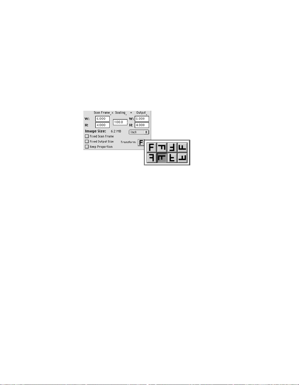
Transform
The Transform command allows you to rotate (at 90-degree increments) and / or
flip (horizontally or vertically) the image . The T ransform command will take
effect both in the Preview scan image and Job Panel windows.
To use the Transform command:
1. Click the Transform button in the Settings window .
2. From the options that appear, choose the reorientation icon representing the
Transform setting that fits your need.
Reference: The Settings Window 63
Page 73

Scanner Profile
The Scanner Profile is a feature that lets you select different ICC scanner profiles
for your scan job other than the default profile. In ScanWizard Pro TX, a default
scanner profile is bundled with your scanner software package. It is always
selected unless you have created your own profile and have added it to the list.
In the example shown below, the Kodak Positive film profile is the default profile
for the ArtixScan 4000t with positive slide as original. The default profile
changes when the original is negative film.
Drop-down menu arrow
Scanner profile info
(PC only)
Default scanner profile
To select your custom scanner profile, click the drop-down menu arrow located
to the right of the Scanner Profile button.
To create a scanner profile, use the Microtek Scanner ICC Profile (MSP)
program which is also bundled with your software package. For more details on
how to use MSP, refer to the MSP documentation.
For Mac users
After clicking the drop-down menu arrow, the Scanner Profile dialog box (see
below) will appear. This dialog box allows you to select your scanner pr ofile and
also lets you view the profile information of the selected scanner profile.
Menu contains the scanner profiles that match your current
scanner model and are found in the ColorSync™ Profiles folder
in your System folder by default.
Checking this option lets you immediately see changes applied by the
selected scanner profile to the preview image.
For PC users
The custom scanner profiles (if any) will be listed in the drop-down menu.
64 Microtek ScanWizard Pro TX for Mac & PC
Load Profile button lets you
select a scanner profile in
another folder in your system.
Profile Info section shows the
profile of the currently selected
scanner (in this case, the
ArtixScan 4000t)
Page 74

Image Category
ScanWizard Pro TX provides several predefined image
categories that can help improve your output image close to
your desired quality.
To select the correct image category for your original, go to
the Settings window and choose the option you wish from
the Image Category menu. Select the image category that
corresponds most closely to the image characteristics of
your original. The selected image category provides a
starting point for predefined settings that can be applied to your image and
bring out characteristics specific to that image type.
• None: No image category conversion.
• Standard: An image that does not fall into any of the described below. Y ou
can also use this category for images of good quality (neither underexposed
nor overexposed, with accurate color and tones).
• Landscape: An image with cool atmosphere, broad tonal variation and
a wide hue range. Examples include natural scenery, skyline with an expanse
of blue sky, mountains and fields.
• Portraits (Skin T ones): An image with dominant skin tones and mid-tone
details present. Examples include portraits and objects with fleece- or skinlike covering.
• Jewelry (Gold T ones): An image featuring dominant gold / silver hues.
Examples include gold and silver jewelry , silverware.
• Sunsets: An image with warm reddish hues or a color cast reminiscent of
sunsets. Examples include scenes at dusk or twilight and images of the Grand
Canyon.
• Metallic Subjects: An image with broad highlight and shadow details but with
very narrow mid-tone details. Examples include audio equipment, TV sets,
cameras.
• High Keys: An image with broad highlight tonal variation but with less
shadow detail. Examples include snow-covered landscapes, wedding gowns,
white-washed structures.
• Low Keys: An image with broad shadow tonal variation but with less highlight
detail. Examples include nighttime scenery , dark suits and clothing, a coal pit.
• Underexposed: An image with compressed tonal variation particularly in the
shadow areas, characterized by an overall dark appearance typical of
underexposed positive film.
• Overexposed: An image with compressed tonal variation particularly in the
highlight areas, characterized by an overall bright appearance typical of
overexposed positive film.
Reference: The Settings Window 65
Page 75

Image assigned “ Standard” image category Image assigned “ Overexposed” image category
In the example above, an overexposed
original is shown in two different image
categories. Because the original was
overexposed to begin with, choosing the
Overexposed image category had the result of
neutralizing the exposure, resulting in a
better image.
The same original did not fare as well when it
was assigned the Standard image category
(too bright overall, not enough contrast),
because this image category is best used for
originals of fairly good quality (sharp, neither
underexposed nor overexposed) and not, in
this case, for an original with flawed
exposure settings.
This example then shows the importance of
choosing the correct image category that
corresponds most closely to your original to
obtain optimal results.
66 Microtek ScanWizard Pro TX for Mac & PC
Page 76

Advanced Image Correction Tools
The Advanced Image Correction (AIC) tools are integral part of ScanWizard Pro
TX. With the AIC tools, you can adjust or enhance images right from within
ScanWizard Pro TX and preview the changes to your image before the final
scan.
These topics are covered in the following pages:
• The LCH Color Model
• AIC tools in LCH vs. Native Mode
• AIC tools and your image type
• W orkflow for optimizing images
• How to access the AIC tools
• Elements of the AIC dialog box
• The Action buttons
• Discussion of the individual AIC tools
Reference: The Advanced Image Correction Tools 67
Page 77

The LCH Color Model
One of ScanWizard Pro TX’s strengths is its ability to let you work in the LCH
color space. Unlike the RGB color model, which corresponds to the color space
as defined in monitors and printers, the LCH color model is a more intuitive way
of working with colors, based on the values of Lightness (the “L” in LCH),
Chroma (C), and Hue (H). For instance, if you wish to change the color of the
sky in an image to a darker blue, your own eye — and your own judgment —
will be the guide to making those color changes. This is easier than, say, knowing
the mathematical equivalent in RGB or CMYK values that would correspond to a
“dark sky blue”.
The LCH model, in effect, makes it easier to comprehend colors as they are
couched in the terms we are familiar with: Lightness (how dark or light a color
is), Chroma or saturation (how rich or dull a particular hue of green is), and Hue
(the property that distinguishes, say, the color red from the color blue.)
In the LCH color model, colors of equal brightness lie on a single plane of the
model, as shown below. Red and green lie opposite each other on the horizontal
axis, as blue and yellow lie opposite each other on the vertical axis.
On the color sphere shown below, you can see how the different LCH properties
play out:
• The different hues (red, green, yellow, blue) are spread around the spher e .
• The chroma (saturation) for each hue increases from the center of the
sphere outward, with the most saturated colors lying on the edge of the
sphere.
• The brightness values increase from the bottom of the model to the top.
68 Microtek ScanWizard Pro TX for Mac & PC
Page 78

AIC Tools in LCH vs Native Color Mode
ScanWizard Pro TX lets you choose the color space in which you wish to edit
and work with color images.
• Select LCH mode if you wish to edit or correct images in terms of color
perception according to the human eye, based on the properties of Lightness, Chroma, and Hue. This is the default mode.
• Select Native mode if you wish to edit or correct the individual RGB / CMYK
channels of an image.
LCH mode is the default working color space when you first start ScanWizard
PrPr
eferefer
Pro TX. To switch to Native mode, click on
MorMor
window menu bar. Then click
MorMor
e Pre Pr
When click the
Color SpaceColor Space
Color Space option, and choose Native mode. The same procedure applies in
Color SpaceColor Space
switching from Native mode back to the LCH color space mode.
All the AIC tools are available when you work in the default LCH color space. A
different set of AIC tools is available when you choose to work in the Native
color space.
Mor
MorMor
e Pr
e Pre Pr
eferefer
efer
eferefer
e... e...
Mor
e... co m m a n d f rom t h e b ottom of the menu.
MorMor
e... e...
ences ences
ences dialog box comes up, go to the
ences ences
encesences
Pr
efer
ences from the
PrPr
eferefer
encesences
PrPr
Pr
PrPr
WW
W
WW
evieweview
eview
evieweview
orkingorking
orking
orkingorking
LCH Color Space AIC Tools Native Color Space AIC Tools
Reference: The Advanced Image Correction Tools 69
Page 79

AIC Tools and your Image Type
Not every image correction tool is available for the various types of scan
material and output images. Non-applicable AIC tools are dimmed when the
selected image type is not supported by such tools.
RGB CMYK Lab Gray Line-art B & W Remark
Diffusion
Dynamic Range ü ü ü ü
White/Black Points ü ü ü ü ü *
Gradation ü ü ü ü LCH mode only
Color Cast ü ü ü LCH mode only
Saturation ü ü ü LCH mode only
Selective ü ü ü LCH mode only
Tone Cur ve ü ü ü ü
Filter ü ü ü ü ü
Brightness & Contrast ü ü Native mode only
Color Correction ü Native mode only
**
*If output image type is Line art, Gradation tool becomes the “ Threshold” tool.
**
70 Microtek ScanWizard Pro TX for Mac & PC
Page 80

Workflow for Optimizing Images
To prepare and optimize your images for the final scan, we recommend the use
of the Advanced Image Correction tools in the sequence that they appear in the
Settings window . Following this or der will significantly influence the overall
quality of your images.
Dynamic Range
1
Manual or auto-determine image
density range (darkest tone to lightest
tone)
Gradation
3
Manual or auto-adjust
midtones of the Lightness
channel “L”
Saturation Curve
5
Adjust image
saturation by
manipulating the
saturation curve
White & Black Points
2
Manual or auto-adjust
shadow and highlight
points
Color Cast
Adjust gray balance by
4
removing color cast or
adjust to desired cast by
adding color cast
Selective Color
6
Manipulate a specific
color range without
affecting other colors
Tone Curve
7
Adjust tonal
distribution of each
channel of a CMYK/
RGB image
Filter
8
Apply a particular filter
for special effects
(e.g., unsharp masking
to sharpen image)
Reference: The Advanced Image Correction Tools 71
Page 81

The sequence is the same if you are working in Native color mode. However, the
Gradation, Color Cast, Saturation, and Selective Color tools (#3 to #6) will not
be available. The Brightness / Contrast and Color Correction tools are offered in
their place.
The Brightness /
Contrast and Color
Correction tools are
offered in the Native
color mode
72 Microtek ScanWizard Pro TX for Mac & PC
Page 82

Accessing the AIC Tools
1. To access an AIC tool, click a particular tool in the Settings window or
choose its counterpart in the Correction menu in the Preview window.
2. After clicking a tool, the AIC dialog box appears. The elements of the AIC
dialog box are explained in the next section.
1
2
Reference: The Advanced Image Correction Tools 73
Page 83
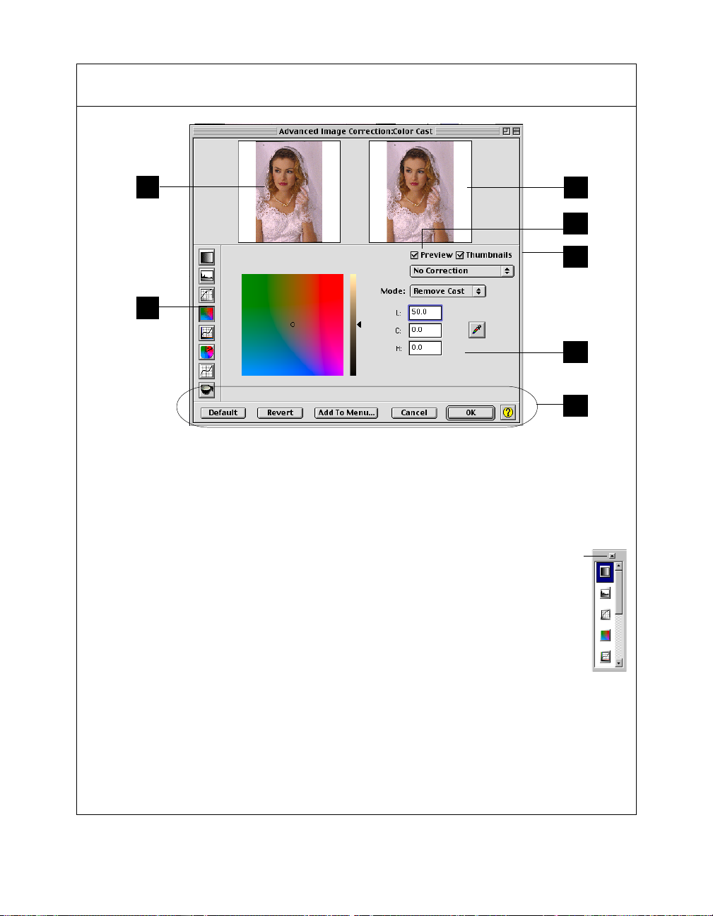
Elements of the Advanced Image Correction screen
1
3
1 Left Thumbnail: This shows the image
before enhancements are applied.
2 Right Thumbnail: This shows the image
after enhancements are applied.
3 Advanced Image Correction Tools (AIC):
These tools adjust or enhance your
images. Click any tool in this area, and
see how the core of the AIC screen (#6)
changes to reflect the properties of that
tool.
4 Preview option: If checked, changes or
enhancements are applied immediately
to the Preview window prescan image. If
unchecked, changes are seen only after
you close the AIC dialog box.
5 Thumbnail Show/Hide option:
For MacFor Mac
For Mac - Check to show the before
For MacFor Mac
and after thumbnails. Uncheck to hide
thumbnails in the AIC screen.
Thumbnail Show/
Hide arrow
For PCFor PC
For PC - Click the thumbnail
For PCFor PC
Show/Hide button to toggle
between hide and show .
6 Core of the AIC screen: This is the
heart of the AIC screen, and the
content here changes to reflect
your selected AIC tool.
7 Action Buttons: These carry out a
specific action. See the next section for
more details.
2
4
5
6
7
74 Microtek ScanWizard Pro TX for Mac & PC
Page 84

The Action Buttons and User-Defined Settings
The Action
Buttons
Default button
This button restores all settings to their default ScanWizard Pro TX values.
Revert button
This button cancels out the changes that were made with the current imageenhancement tool. This means that if you used several AIC tools, Revert cancels
the effect of only the last used (or current) tool, and preserves the effects of the
other preceding tools.
Example: If you changed the tone curve, applied filters, changed saturation, then
clicked Revert, the saturation changes will be cancelled out, but the altered tone
curve and filters settings remain in effect.
Reference: The Advanced Image Correction Tools 75
Page 85

Add to Menu button
This button takes note of the settings you have performed, then adds it as a
selection to the Custom pull-down menu in the Settings window .
When you click this button, a dialog box comes up, and you can enter the name
of the new custom setting to be added. For instance, the added setting can be
called “Custom 1”. This way, you can retrieve and load the setting in the future.
Macintosh Windows
Cancel button
This button cancels out all image-enhancement changes you have made to the
current scan job, and then closes the AIC dialog box.
Example: If you applied filters, changed the curve, and then clicked Cancel, none
of the changes will take effect, and you exit the AIC dialog box.
OK button
This button applies to the current scan job whatever image enhancements you
have performed, and then closes the AIC dialog box.
76 Microtek ScanWizard Pro TX for Mac & PC
Page 86
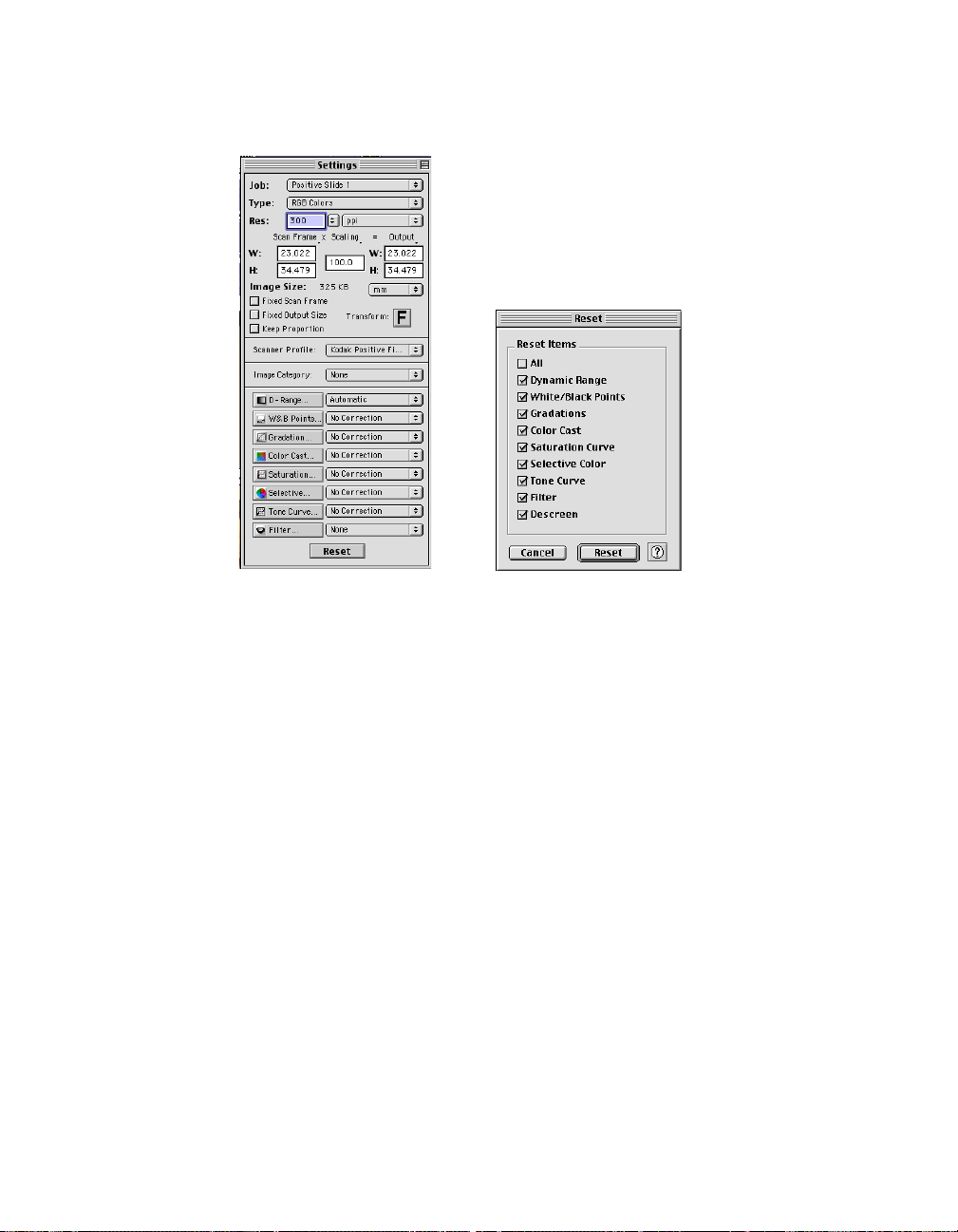
The Reset button
This button brings up the Reset dialog box, where you can specify which AIC
setting you wish to reset by checking its corresponding AIC check box. When
you click the Reset button, the checked AIC settings are restored to their default
values.
Example: If you changed the tone curve and saturation, then checked the
saturation option in the Reset dialog box and clicked Reset, the saturation setting
of the scan job is restored to its default value. The altered tone curve, however,
remains in effect. If you reset both tools, then both are restored to default
values.
Example: If you increased saturation, changed the gradation curve, and then
clicked OK, all the changes are applied, and you exit the AIC dialog box.
Reference: The Advanced Image Correction Tools 77
Page 87
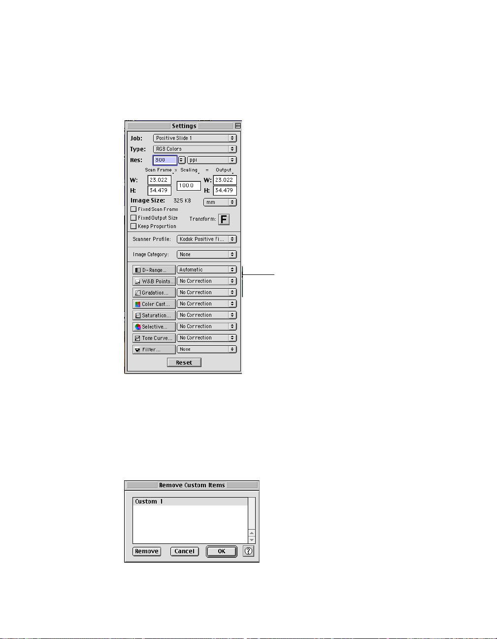
Loading / retrieving user-defined AIC settings
Y ou can always load or retrieve any custom or user-defined settings. To do this,
simply go to the AIC tool of your choice, then choose the user-defined setting
you have made from the Custom pull-down menu of the Settings window.
Custom setting to
be retrieved or
loaded
Removing user-defined AIC settings
T o r emove a user-defined setting, go to the AIC tool - Custom pull-down menu of
the Settings window, then choose Remove Settings from the menu. When a dialog
box appears like the one below, select the particular setting to be removed, then
click Remove in the dialog box.
78 Microtek ScanWizard Pro TX for Mac & PC
Page 88

Dynamic Range tool
The Dynamic Range tool is used to set the density capture range of the scanner
and displays the density distribution (histogram) of the image to be scanned.
The Auto range (default) feature automatically determines the Dmin (minimum
density, lightest tone) and Dmax (maximum density, darkest tone) of the image,
and sets the scanner capture range.
Drag sliders to
adjust custom
Dmin/Dmax
settings
Enter custom
Dmax setting
here
Enter custom
Dmin setting here
See next page
for Eyedropper
tool details
Select this option
to adjust the Dmin/
Dmax settings of
the RGB channels
simultaneously.
Select this option to
adjust the Dmin/Dmax
settings of the RGB
channels
individually.
Select the individual
channel (red, green, or
blue) that you wish to
control.
This option is disabled if
you choose the
Color Balance
the Dmin/Dmax setting.
Adjust
option of
Click to apply the
automatic setting (a
ScanWizard ProTX
algorithm)
Click to revert to the setting at
startup of current session
Shows the density
value at pointer
position within the
histogram
Reference: The Advanced Image Correction tools 79
Page 89
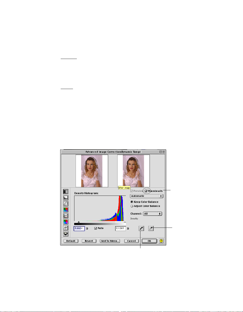
Eyedropper tools
Y ou can use the Black and White Eyedr opper tools (instead of the sliders) to
define the Dmax (darkest tone) and the Dmin (lightest tone) settings,
respectively.
For Mac
Click the Eyedropper tools in the Dynamic Range dialog box. Then move to the
thumbnail image in the dialog box or to the preview image in the Preview
window , and choose your Dmax / Dmin point directly fr om the image.
For PC
Move the mouse pointer into the prescan image in the Preview window. Notice
that the pointer turns into the Black Eyedropper . To turn the pointer into the
White Eyedropper , press the Alt key. Then choose your Dmax / Dmin point
directly from the image.
• To define the Dmax (darkest tone) setting, use the Black Eyedropper tool.
• T o define the Dmin (lightest tone) setting, use the White Eyedr opper tool.
80 Microtek ScanWizard Pro TX for Mac & PC
Enable this
check box to
show the
adjustment
effect on the
prescan image
White
Eyedropper for
Dmin settings
Black Eyedropper for
Dmax settings
Page 90

White & Black Points tool (LCH color mode)
The White & Black Points tool is used to change the shadow and highlight points
of an image. (See note on next page for additional descriptions.)
By using this tool, you can manipulate an image to either bring out the highlights
in a very dark image, or bring out more of the shadows in a very light image.
The White & Black Points tool can also be used to neutralize the color cast in
the highlight and shadow regions.
Drag sliders to
define custom
shadow and
highlight
settings
Enter custom Lightness,
Chroma & Hue values for
Shadow (Black area) here.
C & H values are applicable
Neutralize - Shadow
only when the
box is enabled.
Auto
check
Click to let ScanWizard
Pro TX determine the
shadow and highlight
points automatically
See next page
for Eyedropper
tool details
Observe histogram
values for
distribution of the
Lightness “L”
channel in the
image, as cursor is
swept around
histogram
Check to auto
neutralize unwanted
color casts in
Shadow (black) area
or Highlight (white)
area
Click to bring up the
White/Black points
setup dialog box. For
more details, see the
section titled
Black Points Setup
(under the
Preferences menu in
the Preview window).
White &
Enter custom Lightness, Chroma
& Hue values for Highlight (White
area) here. C & H values are
applicable only when the
Neutralize - Highlight
Auto
check box
is enabled.
Reference: The Advanced Image Correction tools 81
Page 91
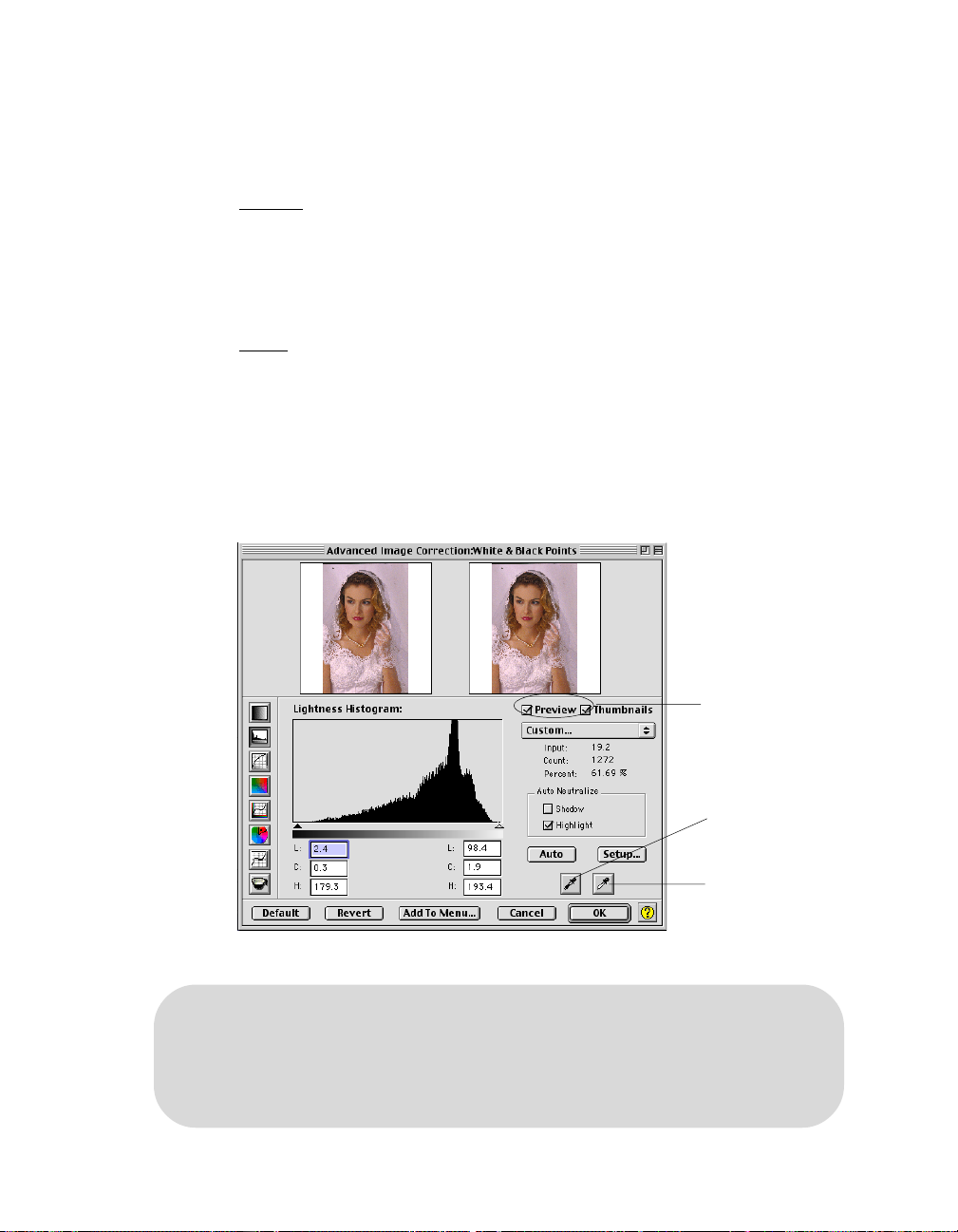
Eyedropper tools
Y ou can use the Black and White Eyedr opper tools to define the Shadow and
Highlight points.
For Mac
T o do this: Click the Black or White Eyedr opper tools in the White & Black
Points dialog box. Then move to the thumbnail image in the dialog box or to the
preview image in the Preview window, and choose your Black/White Point
directly from the image.
For PC
Move the mouse pointer into the prescan image in the Preview window and
notice how the pointer turns into the Black Eyedropper. To turn the pointer into
the White Eyedropper , press the Alt key. Then choose your Black/White point
directly from the image.
• To define the Black (shadow) point, use the Black Eyedropper tool.
• T o define the White (highlight) point, use the White Eyedr opper tool.
The shadow point is defined as the lightness value “ L” in an image that is output as black
(mapped to the Minimum Output Level), while the highlight point is defined as the lightness
value “ L” that is output as white (mapped to the Maximum Output Level).
The default values of the Minimum Output Level and Maximum Output Level are L=5.0 and
L=95.0, respectively.
82 Microtek ScanWizard Pro TX for Mac & PC
Enable this check
box to show the
adjustment effect on
the prescan image
Black Eyedropper to
define the Shadow
point
White Eyedropper
to define the
Highlight point
Page 92
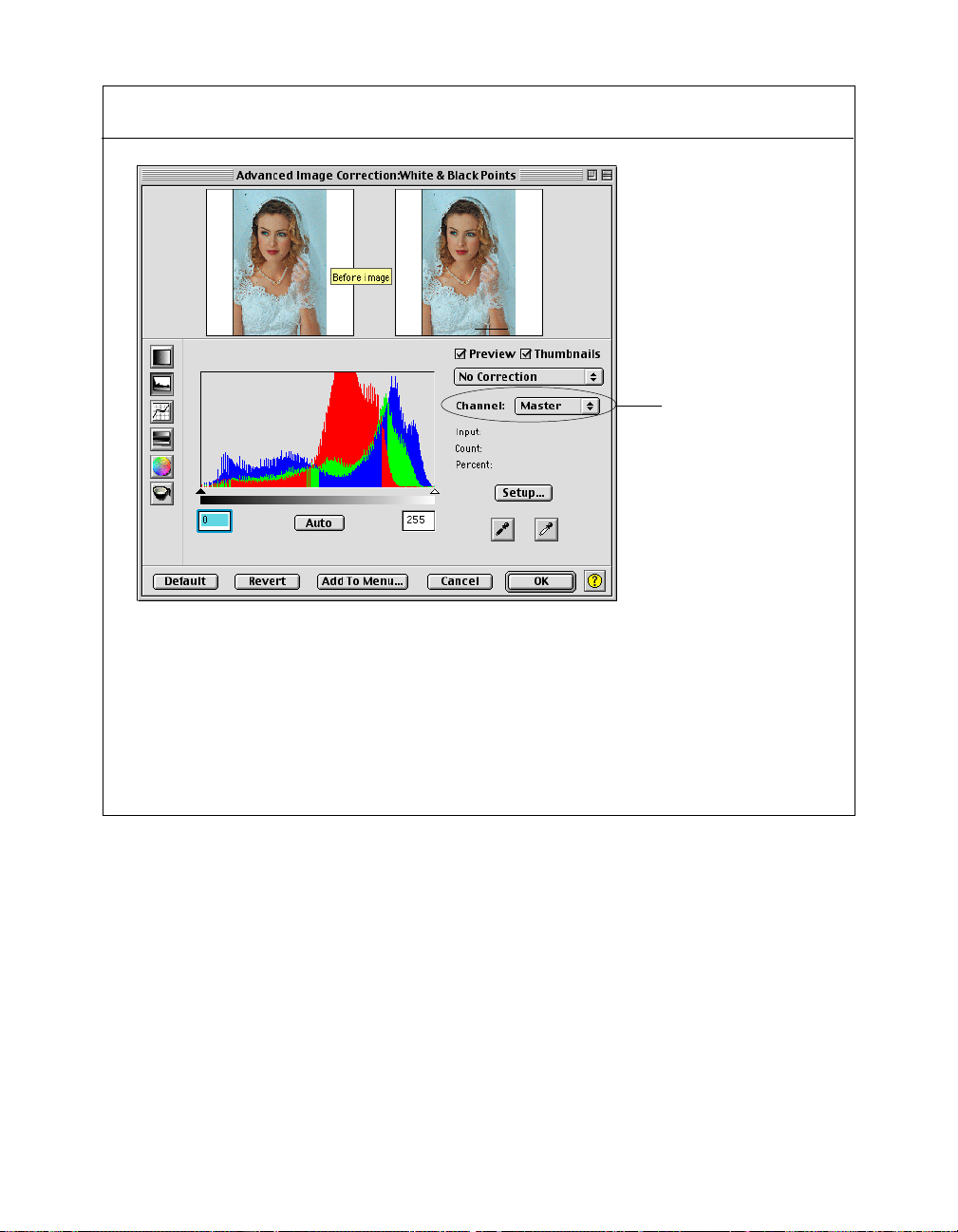
The W&B Points dialog box in Native color mode
Select the individual
channel (red, green, or
blue) that you wish to
control.
In Native color mode, the White & Black Points dialog box allows you to modify the
histogram in your RGB channel. Channels can be modified individually or collectively
(when you select “All”) in the Channel box.
Following the selection of your channel, you can move the black and white sliders below
the histogram to set the shadow and highlight values, respectively. The edit boxes below
the sliders will reflect those values.
Reference: The Advanced Image Correction tools 83
Page 93

Gradation tool
The Gradation tool lets you adjust the midtones (the mid-level grays) of the
lightness channel “L” of an image without altering the color itself. This is because
even with changes to the luminance or lightness value, the chroma and hue
values are kept constant.
T o prevent color images fr om losing saturation when adjusting the lightness,
ScanWizard Pro TX provides a Saturation Range option. With this option, colors
outside of a given chroma range are not affected by the manipulation of the
gradation curve.
.
The Curve shows the relationship of
the brightness changes across the
middle pixels between the resulting
image and the original. When you
open the Curves dialog box, the line
on the graph is diagonal because
the Input and Output values are the
same.
When the curve is moved up or
down, the relationship between
input value and output value
changes accordingly.
How to read the curve
Original curve
• In areas where the curve is
moved down, pixels in that
portion of the image are
darkened.
• In areas where the curve is
moved up, pixels in that portion
of the image are lightened.
Contrast in an image can be seen by
the angle of the line. The steeper the
slope, the higher the contrast. The
closer the line is to horizontal, the
lower the contrast.
84 Microtek ScanWizard Pro TX for Mac & PC
Modified curve
Page 94

The Gradation dialog box
Choose the method to
display the Gradation
curve. Default is
Curve. Alternate
methods are Line and
Gamma.
Click Auto to let
ScanWizard Pro
TX calculate the
Gradation setting
automatically.
Coordinates of
pointer position
within the grid
See next Section
for Eyedropper
tool details
Click to create handles from
which to drag and manipulate
a segment of the curve.
The more handles are created,
the easier and smoother it is to
manipulate the curve.
To remove a handle, drag it
off the graph or the grid.
Check to enable the Saturation Range option.
Then drag the sliders or enter the values in
the edit boxes to define the saturation
(chroma) range. The colors outside the
chroma range will not be affected by the
Gradation curve.
In this example, the lower chroma section (0
to 50) will be affected by the Gradation
adjustment. The higher chroma section (51 to
100) outside the chroma range will not be
affected.
Defining a chroma range is helpful if you wish
to prevent images from losing saturation or
color intensity.
Reference: The Advanced Image Correction tools 85
Page 95

Appearance of curve if
Method chosen is “ Line”
Appearance of curve if Method chosen is “ Gamma.”
Dragging points on the curve to a Gamma value above 1.00, will
lighten the dark tones. Dragging points on the curve to a
Gamma value below 1.00 will add shadows to light tones
86 Microtek ScanWizard Pro TX for Mac & PC
Instead of dragging the
Gamma handle, you can also
enter directly the appropriate
Gamma value in the edit box.
Page 96

Eyedropper tool (Mac only)
Y ou can also use the Black and White Eyedr opper tools to define the Saturation
Range.
T o do this: Click the Eyedr opper tools in the Gradation dialog box. Then move to
the thumbnail image in the dialog box or to the preview image in the Preview
window, and choose the setting for your high chroma and low chroma range.
• Use the Black Eyedropper tool to define your low chroma range setting.
• Use the White Eyedropper tool to define your high chroma range setting.
Black & White
Eyedropper tools
(Mac only)
Reference: The Advanced Image Correction tools 87
Page 97

Color Cast tool
The Color Cast tool is used to eliminate any unwanted color casts in an image, as
well as to add a color cast without altering the lightness channel “L” values.
Lightness
Handle
Color (Hue or
Chroma)
Handle
Select whether to add or
remove a color cast.
“ Remove Cast” is the
default.
Enter values in the edit
boxes and see how the
handles get positioned in the
color box.
Conversely, move the
handles in the color box
and see how the values
change in the edit boxes.
Color Cast Eyedropper.
See next page for details.
88 Microtek ScanWizard Pro TX for Mac & PC
Page 98
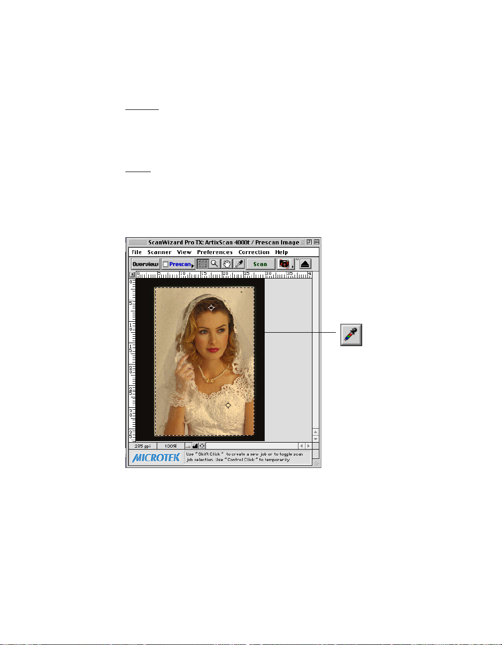
Eyedropper tool
It is more convenient to use the Color Cast Eyedropper tool in removing or a
adding color cast.
For Mac
Click the Color Cast Neutral Eyedropper in the Color Cast dialog box. Then
move to the thumbnail in the dialog box or the preview image in the Preview
window, and pick the color cast to be added or removed directly from the image.
For PC
Move the mouse pointer into the prescan image in the Preview window and
notice how the pointer turns into a Neutral Eyedropper. Then pick the color cast
to be added or removed directly from the image.
Use the Color Cast Neutral
Eyedropper to add or remove
a color cast.
Reference: The Advanced Image Correction tools 89
Page 99

Saturation tool
The Saturation Curve tool lets you increase or decrease the color intensity
(chroma or saturation) of an image without altering its hue and lightness values.
Enable this check box to
show the adjustment effect
on the prescan image
Select Saturation method.
“ Curve” is the default
Select Saturation Range.
“ All” is the default. Other
selections let you change
the saturation for
Highlights only, Midtones
only, or Shadows only.
Drag the curve above the default
diagonal line to increase
saturation. Drag the curve below
the default diagonal line to
desaturate color into gray levels.
90 Microtek ScanWizard Pro TX for Mac & PC
Coordinate
information of the
mouse pointer
position on the
grid
Page 100

Selective Color tool
The Selective Color tool is used to perform color correction to a specific color
range without altering the other colors in an image. This is done either to
increase the visual impact of a color or to completely change the relationship of
the targeted color to the other colors in the image.
Hollow dot
represents the
Chroma and Hue
Resizing this area
affects the Delta
button to define a
new “From” color
values
This sector
represents the
values of the
“ Fr om” color.
LCH values
Click the New
to be changed.
This box shows the
affected colors: the
“ From” color (left
column) and the “ To”
color (right column)
Drag these sliders
along the vertical slider
to change the lightness
(“ L” ) value of the
“ From” color, then the
“ To” color
Neutral Eyedropper
tools may be used to
pinpoint “From” color
(left column) and to
adjust area of the
color to be corrected
or the Delta LCH
value (right column)
Expansion arrow to
access and process
Selective colors in CYMK/
Reference: The Advanced Image Correction tools 91
The Delta LCH
values expand or
reduce the region
of the color area
to be affected
RGB values
These edit boxes
show the values
of the “ From”
and “To” color.
Enable check box to
view areas on the image
that will be affected by
the “From” color change
 Loading...