

Page 1

Microtek ScanWizard Pro
Reference Manual
for Windows
i
Page 2

Copyright 2009 by Microtek International, Inc.
All rights reserved.
Trademarks
Microtek®, ArtixTM, and ScanWizardTM Pro are trademarks or registered trademarks of Microtek International
®
Inc. Adobe
and Acrobat® are registered trademarks of Adobe Systems Incorporated. Macintosh® and Apple
are registered trademarks of Apple Computer, Inc. Windows® is a registered trademark of Microsoft
Corporation. All other products or name brands are trademarks of their respective holders.
Important
Documents that you scan may be protected under copyright law. The unauthorized use of such documents
could be a violation of the rights of the copyright holder. Microtek bears no responsibility for the
unauthorized use of copyrighted materials.
To obtain optimal results from the Microtek scanning software and user's manual, you should be familiar with
such Windows concepts as pointing, clicking, dragging, and selecting from menus and dialog boxed. If these
things are new to you, refer to your Microsoft Windows User's Guide. 031509
®
Microtek International, Inc.
6, Industry East Road 3, Science Based Industrial Park, Hsinchu, 30077, Taiwan
Tel: 886-3-5772155, Fax: 886-3-5772598, http://www.microtek.com
ii
Page 3

Contents
Reference 1
ScanWizard Pro for Windows .........................................................................................2
Bringing up the ScanWizard Pro for Windows ................................................................3
Exiting ScanWizard Pro ..................................................................................................3
The Preview Window ..................................................................................................... 4
The Menu Bar ......................................................................................................... 5
The Scanner Menu ..................................................................................................6
Scanner Model ................................................................................................ 6
TCP/IP Scanner Setup .......................................................................................7
Get Current Scanner Info ................................................................................ 9
Scanner Probe ................................................................................................. 9
Scanner Control (Power Saving Control) ........................................................ 10
The View Menu .................................................................................................... 11
Overview Image ............................................................................................. 11
Prescan Image ............................................................................................... 12
Resize Window to Fit ..................................................................................... 13
Bring Settings Window to Front ..................................................................... 14
Show/Hide commands ................................................................................... 14
Show/Hide All Tag Windows .......................................................................... 14
Show/Hide White/Black Markers ................................................................... 14
The Preferences Menu .......................................................................................... 15
Scan Material ................................................................................................. 16
The Scan Material Status icon ........................................................................ 17
Color Matching Setup .................................................................................... 18
Display using monitor compensation....................................................... 18
Display ................................................................................................... 18
Native mode RGB color matching (Native Color Mode only) .................... 19
Embed ICC destination profile in scan image ........................................... 19
RGB Destination ..................................................................................... 19
CMYK Destination .................................................................................. 20
Add Profiles ............................................................................................ 20
Info ........................................................................................................ 21
Preview .................................................................................................. 21
Refresh ................................................................................................... 21
iii
Page 4

White/Black Points Setup ............................................................................... 22
Auto Clipping ......................................................................................... 22
Output Levels ......................................................................................... 22
H/S Markers ........................................................................................... 23
Cursor Auxiliary Lines ................................................................................... 24
Overview Setup ............................................................................................. 26
Overview Area .........................................................................................26
Unit .........................................................................................................26
Fast Overview......................................................................................... 27
Overview automatically when ScanWizard Pro is started ......................... 27
Keep Overview image ............................................................................. 27
Show confirmation message box if there is any prescan image ................. 27
Preview ................................................................................................... 27
Prescan Setup ................................................................................................ 28
Fast Prescan ........................................................................................... 28
Keep All prescan images.......................................................................... 28
Prescan Image Margin ............................................................................ 28
Prescan Image Dimension ....................................................................... 28
Background Prescan ............................................................................... 28
Monitor Gamma Setup................................................................................... 29
Monitor Gamma ..................................................................................... 29
Invert ............................................................................................................ 30
More command ............................................................................................. 31
Smoked Glass Background...................................................................... 31
Confirmation Message ............................................................................ 32
Color Space Mode .................................................................................. 32
Scan Mode ............................................................................................. 32
Best Quality: Multiple Sampling ................................................................33
Interpolation Mode ................................................................................ 33
Working Directory .................................................................................. 33
The Help Menu ..................................................................................................... 34
About ............................................................................................................ 34
The Tool Buttons .................................................................................................. 35
Scan Frame tool............................................................................................. 36
Scan Frame Keyboard Shortcuts ............................................................. 37
Magnify Glass tool ......................................................................................... 39
Pane tool ....................................................................................................... 40
Dropper tool ................................................................................................. 41
iv
Page 5

To create a Tag window ........................................................................... 41
To close the Tag window ......................................................................... 42
Choosing Black and White Droppers....................................................... 42
Input display Mode switch ...................................................................... 42
Black, White, and Color diamonds .......................................................... 42
Setting White/Black points ...................................................................... 43
To restore original settings: ..................................................................... 43
To change the sample size of the Dropper: .............................................. 44
To display color information for a pixel or an averaged area: ................... 44
Dropper Keyboard Shortcuts .................................................................. 44
Action Buttons............................................................................................... 45
Rulers ............................................................................................................ 46
Preview Area ................................................................................................. 47
Auxiliary information ..................................................................................... 48
Preview image resolution: ....................................................................... 48
Zoom scale ............................................................................................. 48
Zoom-out ............................................................................................... 48
Zoom-in.................................................................................................. 48
White/Dark points marker flasher........................................................... 48
The Settings WindowThe Settings Window
The Settings Window
The Settings WindowThe Settings Window
................................................................................................................................................................................
........................................................................................ 49
................................................................................................................................................................................
Output Image Parameters ..................................................................................... 50
Type (Image Type or Scan Mode) .................................................................... 50
Palette .................................................................................................... 51
Dither ..................................................................................................... 51
Resolution ..................................................................................................... 52
Unit selection ................................................................................................ 53
Image Dimension controls ............................................................................. 54
Scan Frame (input) x Scaling = output ..................................................... 54
Scan Frame............................................................................................. 54
Output ................................................................................................... 54
Scaling .................................................................................................... 55
Image Size .............................................................................................. 55
Unit of Measurement .............................................................................. 55
Keep Proportion ..................................................................................... 55
Transform (Rotate and Flip tool) ............................................................. 55
Advanced Image Correction Tools ........................................................................ 57
Available Image Correction Effects ................................................................. 57
Introducing the Image Correction tools ......................................................... 58
v
Page 6

Using the Advanced Image Correction dialog box .......................................... 58
The Action Buttons in the AIC dialog box ....................................................... 59
1:1 Thumbnails ....................................................................................... 59
Hide Thumbnails ..................................................................................... 59
Preview .................................................................................................. 59
The OK button ....................................................................................... 60
The Cancel button .................................................................................. 60
The Default button ................................................................................. 60
The Revert button ................................................................................... 60
The Add to Menu button ........................................................................ 60
To retrieve user-defined AIC settings ....................................................... 61
The Reset button..................................................................................... 61
To remove user-defined AIC settings....................................................... 62
Dynamic Range tool ....................................................................................... 63
The Dynamic Range dialog box ............................................................... 64
White/Black Points tool ................................................................................. 66
The White/Black Points dialog box (Color/Gray image) ............................ 66
The Threshold dialog box (Line-art image) .............................................. 68
Sharpen .................................................................................................. 68
Gradation Curve tool (LCH mode only) .......................................................... 69
How to read the curve ............................................................................ 69
The Gradation Curve dialog box ............................................................. 71
Color Cast tool (LCH Mode Only) .................................................................. 74
The Color Cast dialog box ....................................................................... 74
Saturation tool (LCH Mode Only) .................................................................. 76
The Saturation dialog box ....................................................................... 76
Selective Color Tool (LCH Mode Only) ........................................................... 77
The Selective Color dialog box ................................................................ 77
Tone Curve tool ............................................................................................. 82
The Tone Curve dialog box...................................................................... 82
Filter tool ...................................................................................................... 84
The Filter dialog box .............................................................................. 84
Descreen ....................................................................................................... 88
To use Descreen:..................................................................................... 88
Brightness and Contrast tool (Native Color Mode only) .................................. 89
Brightness............................................................................................... 89
Contrast ................................................................................................. 89
vi
Page 7

Color Correction tool (Native Color Mode only) ............................................ 90
Color Wheel ........................................................................................... 90
Saturation bar......................................................................................... 90
Using the Color Correction tool .............................................................. 91
The Information Window ............................................................................................ 92
Cursor Locator .............................................................................................. 93
Input value .................................................................................................... 93
Output value ................................................................................................. 93
Sample size button......................................................................................... 94
Using the Pixel Display ................................................................................... 94
The Scan Job Queue Window ...................................................................................... 95
Multiple Selections ............................................................................................... 96
How to read the Scan Job window ........................................................................ 97
The New button.................................................................................................... 98
More on the New button ............................................................................. 102
The Duplicate button .......................................................................................... 103
The Delete button ............................................................................................... 105
The Check button ............................................................................................... 105
The Save/Load button......................................................................................... 106
New name auto given if the name already exists ........................................... 107
The Up/Down Position Arrows ........................................................................... 108
Scan to File 109
Entering Scan to File mode .........................................................................................109
How to perform Scan-to-File ...................................................................................... 110
Available File Formats for “Scan to File” Function ...................................................... 112
Appendix A-1
Appendix A: Product and Technical Support .............................................................. A-2
Appendix B: Kodak Color Management System .......................................................... B-1
Appendix C: Photoshop 5.0 Color Settings ................................................................. C-1
Appendix D: Troubleshooting ..................................................................................... D-1
Appendix E: Glossary .................................................................................................. E-1
vii
Page 8

viii
Page 9

Reference
This section is a listing of features found in the ScanWizard Pro for Windows
scanning software.
The reference information is organized in four parts, which shows the four
major windows of the program:
• Preview
• Settings
• Information
• Scan Job Queue
Reference: The Preview window 1
Page 10
ScanWizard Pro for Windows
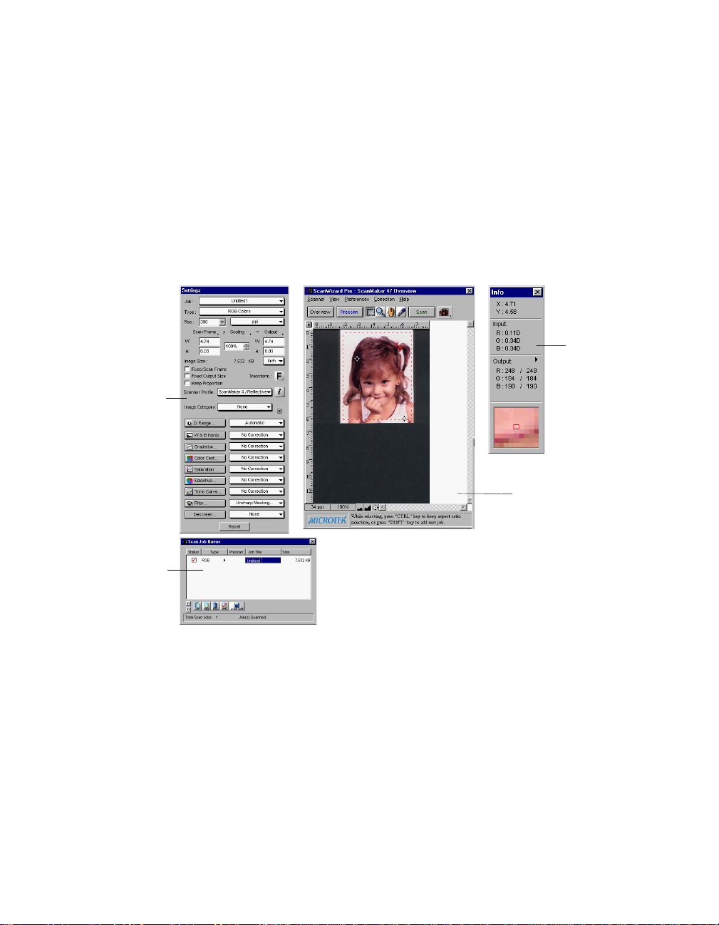
ScanWizard Pro for Windows consists of four major windows: Preview, Settings,
Information, and Scan Job.
The Preview and Settings windows appear automatically after the ScanWizard
Pro is started up. The Scan Job and Information windows appear when you
bring up ScanWizard Pro at the first time. You may hide or show them from the
View menu and click on the commands Show Scan Job Window and Show Info
Window.
window contains
Settings
scanning
parameters for
outputting the
image and
includes image
correction tools
Scan Job
window
provides key
functions in
managing
scan jobs
Information
window
provides
information
on the
Preview
image
Preview
window has
commands and
tools for
controlling the
scanner
2 Microtek ScanWizard Pro for Windows
Page 11
Bringing up the ScanWizard Pro for Windows
Click Start, Programs, select Microtek ScanWizard Pro for Windows, then
Microtek ScanWizard Pro. Alternatively, you may start up your image-editing
software first. When the application opens, choose the command for acquiring
ScanWizard Pro.
The main screen will appear, but the very first time that ScanWizard Pro is
started up, the 4 windows will all appear.
The next time you start up ScanWizard Pro, the main screen will look exactly
like the last time you exited the software. This means that if you had all four
windows open the last time you quit ScanWizard Pro, the same four windows
will appear the next time you start it up.
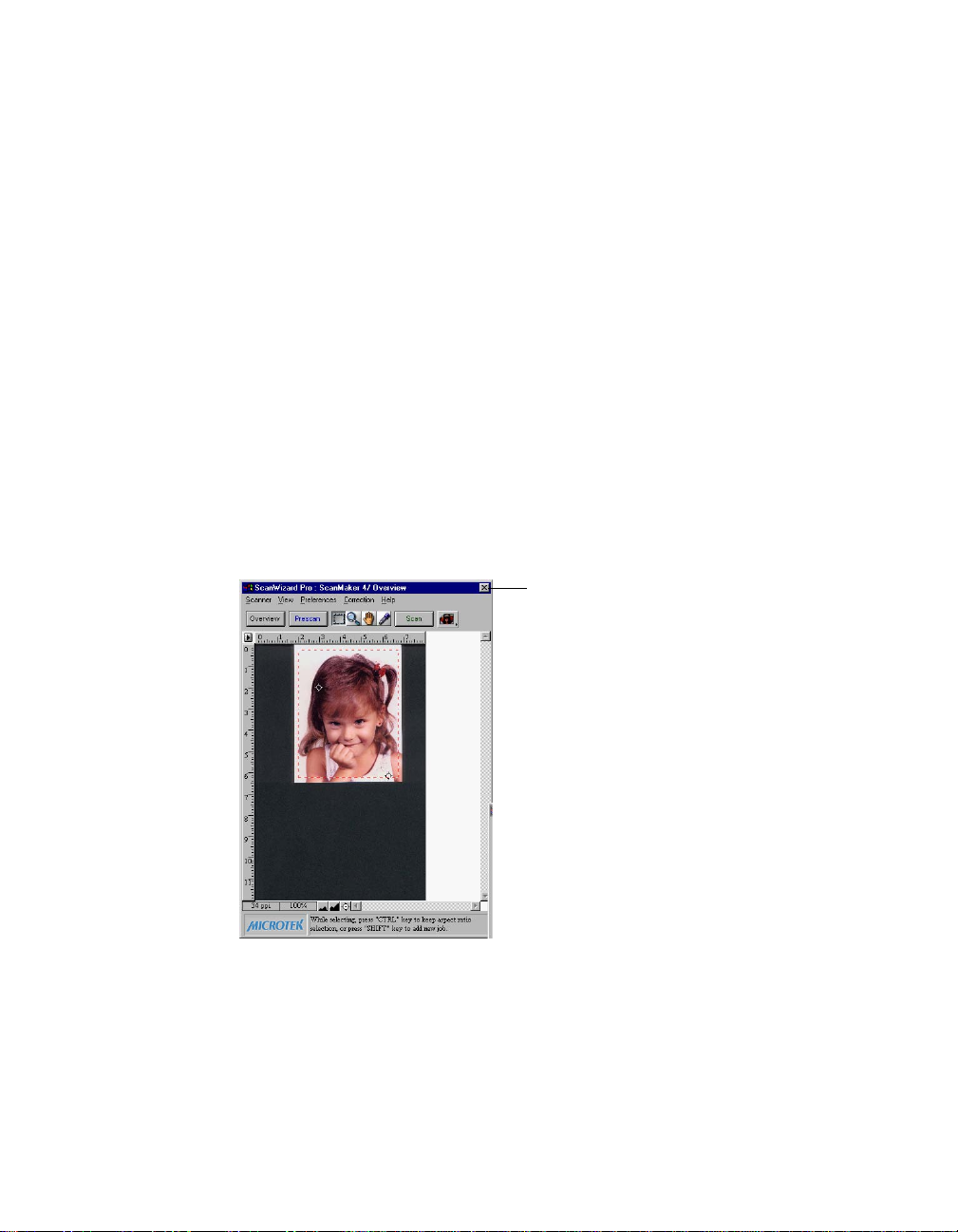
Exiting ScanWizard Pro
To exit ScanWizard Pro for Windows, double click on the close box on the
upper left side of the Preview window.
Double-click
here to exit
ScanWizard Pro
Reference: The Preview window 3
Page 12
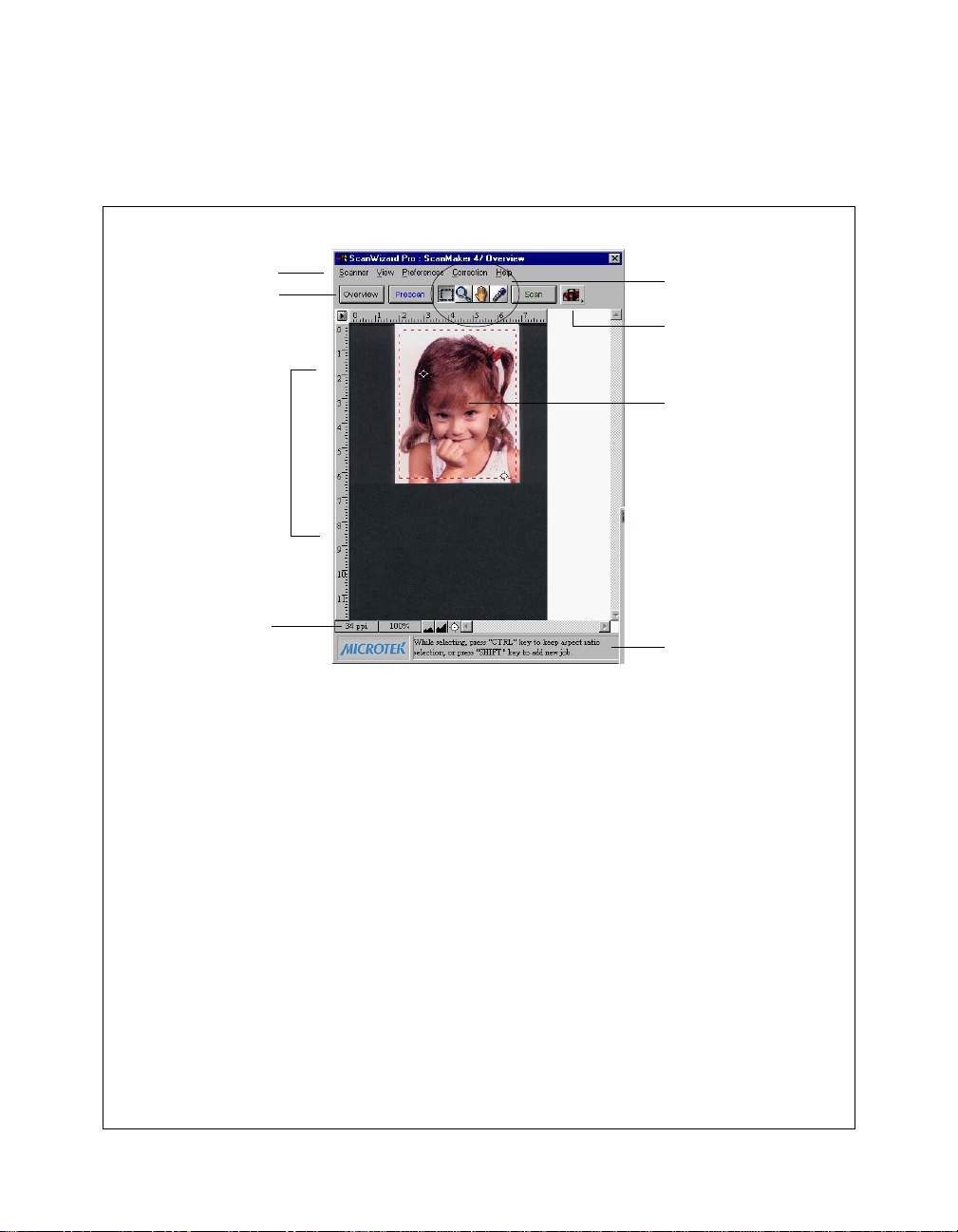
The Preview Window
The Preview window is the most prominent window of the four major windows,
and it includes the various commands and tools for controlling the scanner.
Elements of the Preview window
1
3
6
8
1 The
2 The
3 The
4 The
Menu BarMenu Bar
Menu Bar includes the different menus
Menu BarMenu Bar
for setting up the scanner (Scanner menu),
controlling view options (View menu),
customizing the software (Preferences
menu), Image Correction function
(Correction menu), and accessing on-line
help (Help menu).
T T
ool buttonsool buttons
T
ool buttons simplify the performance
T T
ool buttonsool buttons
of certain tasks. The Tool buttons are (left to
right) Frame, Magnify Glass, Pane, and
Dropper.
Action buttons Action buttons
Action buttons generate a specific
Action buttons Action buttons
action from the scanning software. The
Action buttons include Overview, Prescan
and Batch/Scan.
Scan Material Status icon Scan Material Status icon
Scan Material Status icon shows your
Scan Material Status icon Scan Material Status icon
scan material, whether it's reflective,
positive, or negative.
2
4
5
7
5 The
6
7 The
8 The Auxiliary bar shows 1) The screen
Preview window Preview window
Preview window is where the
Preview window Preview window
Overview or Prescan image appears
after you click on the Overview or
Prescan button.
RulersRulers
Rulers are located on both sides of the
RulersRulers
window to help you with measurement
and alignment.
selected by clicking on the arrow at
the 0,0 point of the rulers.
Status bar Status bar
Status bar shows you some
Status bar Status bar
information for easier operation.
resolution of the preview image. 2)
Zoom scale 3) Zoom out 4) Zoom in 5)
Black/white markers indicator
ruler unitruler unit
The
ruler unit can be
ruler unitruler unit
4 Microtek ScanWizard Pro for Windows
Page 13
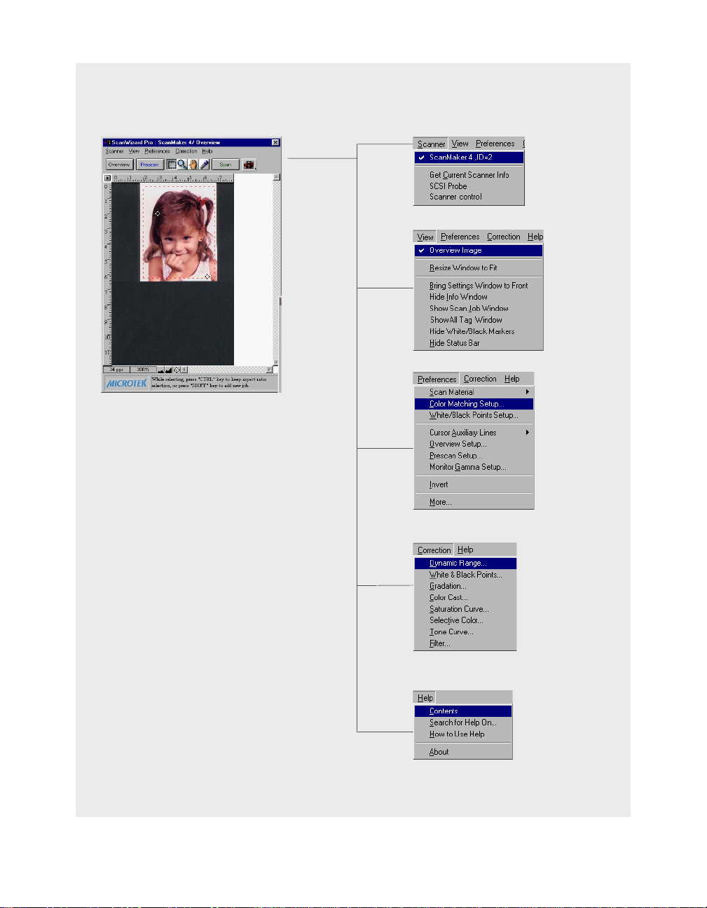
The Menu Bar
Reference: The Preview window 5
Page 14
The Scanner Menu
The Scanner Menu lets you:
• Select your scanner model or select a shared scanner on the local area
network
• Set up TCP/IP scanners
• Get information about current scanner
• Probe both the local and network scanners
• Set idle time for saving power
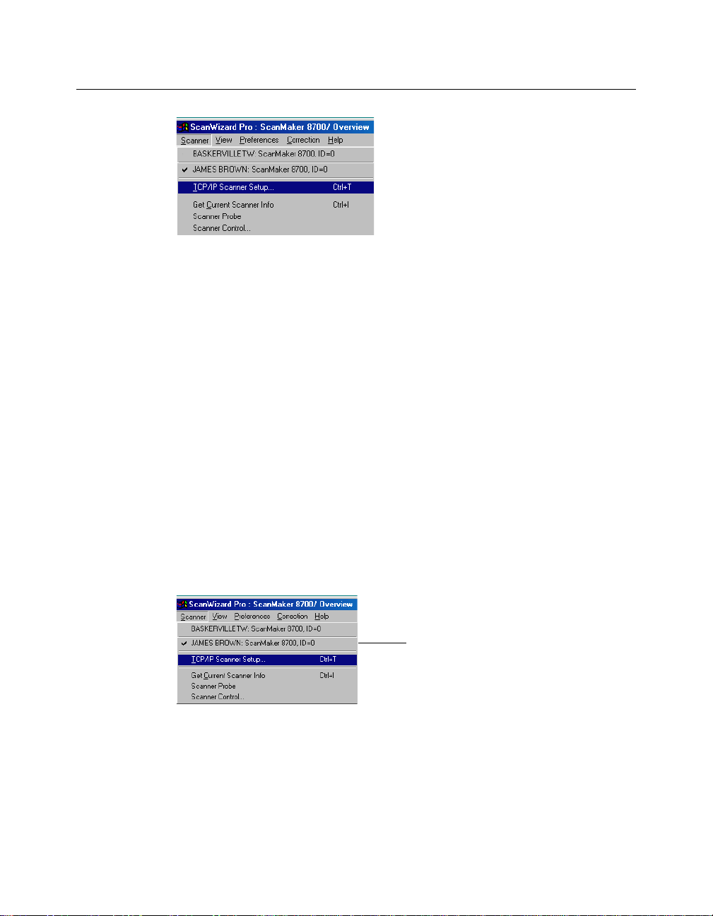
Scanner Model
The top of the scanner menu displays all the scanners with their respective SCSI
IDs. The shown scanners are either your locally connected scanners or the
network scanners; the current scanner is indicated by a check.
Only one scanner can be accessed at a time. To switch among various scanners,
select the scanner to be used.
If you cannot locate a scanner for use, perform a new search for available
scanners. The next time you launch ScanWizard Pro, the connected scanners
will be available for choosing.
6 Microtek ScanWizard Pro for Windows
The scanner with its SCSI ID is
displayed. The current scanner is
marked by a check.
Page 15
Some scanner models feature multiple scanning lenses (one for high-resolution
scanning and one for low-resolution scanning). If the multiple-lens scanner is
detected, a submenu appears for lens selection, and you can choose the option
you want.
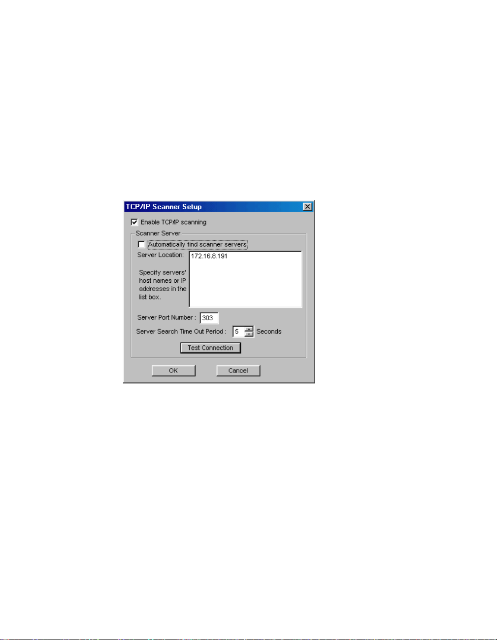
TCP/IP Scanner Setup
This window is the control panel for managing scanner servers. Choose the
“TCP/IP scanner setup” command from the Scanner menu; the following dialog
box appears.
Enable TCP/IP scanning
If checked, your computer is enabled to access remote scanners (scanner
servers) on the network. If unchecked, remote access is disabled.
Auto-search scanner servers
If checked, clicking the Test Connection button displays the IP addresses of
connected scanners. If unchecked, you can type either the host names or the
corresponding IP addresses in the Server Location edit box, then click the Test
Connection or OK button. The Test Connection button lists the information of
the detected scanner servers; while the OK button performs auto searching of
scanner servers without showing information on the detected scanners. The
detected scanners can be selected from the Scanner menu of the ScanWizard
Pro Overview window.
Reference: The Preview window 7
Page 16

Server Location
When the “Auto-search scanner servers” option is checked, the Test Connection
window lists the detected computers with their corresponding scanner IP
addresses. If the option is unchecked, you can type the IP address or the host
computer names. In a local area network, each computer has a unique name for
identifying itself from the others.
Note: The IP address is identified by dot-segregated four-position numbers (e.g.,
172.16.17.135). The four number should be within 0 to 255. The left three numbers of
the connected scanner are the same, in other words, all of the connected scanners appear
as “172.16.17”, but the last number is unique to the respective scanner.
To know the name of the host computer:
• For Windows 95/98/Me users:
Right-click the
PropertiesProperties
Properties, then click the
PropertiesProperties
Network NeighborhoodNetwork Neighborhood
Network Neighborhood on the Windows desktop; select
Network NeighborhoodNetwork Neighborhood
Identification Identification
Identification tab on the server station. The
Identification Identification
computer name is shown.
• For Windows 2000/NT users:
Right-click the
then click the
My ComputerMy Computer
My Computer on the Windows desktop; select
My ComputerMy Computer
Network Identification Network Identification
Network Identification tab on the server station. The
Network Identification Network Identification
PropertiesProperties
Properties,
PropertiesProperties
computer name is shown.
Server Port Number
In a local area network, all connected scanners should use the same server port
number; otherwise, the scanners cannot be found. The default and recommend
port number is 303.
Server Search Timeout Period
This edit box allows you to set the timeout period, after which the scanner
server stops its search. Use the up/down button to increase/decrease the
timeout period or input an acceptable period (1 to 60 seconds).
Test Connection
When you click on this button, based on the settings you have made on the TCP/
IP Scanner Setup window, ScanWizard Pro starts to probe the connected
scanner servers on the network, then lists the detected scanner servers in the
Test Connection window.
8 Microtek ScanWizard Pro for Windows
Page 17
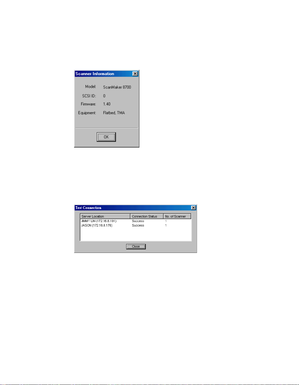
Get Current Scanner Info
This command provides information about your current scanner. When you
choose this command, a dialog box appears showing the scanner model, SCSI ID
number, and firmware version.
Scanner Probe
This command detects both the local and remote scanners on the network.
When scanners are detected, the window below appears.
To select a connected scanner for use, choose it from the Scanner menu of the
ScanWizard Pro Overview window. The selected scanner is shown with a check
mark.
Reference: The Preview window 9
Page 18
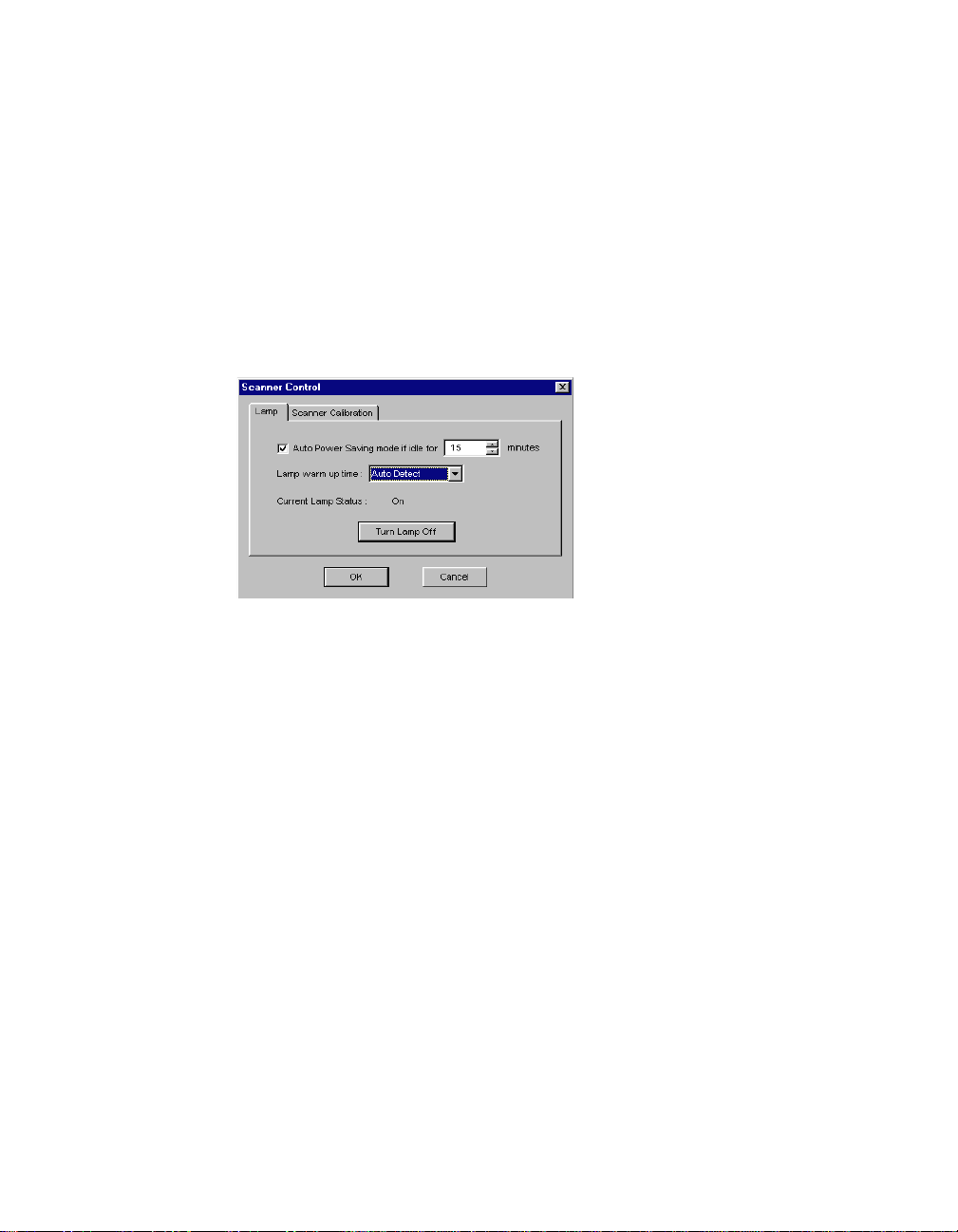
Scanner Control (Power Saving Control)
Not all Microtek scanner models support scanning lamp power saving feature. If
your Microtek scanner is implemented with this function, you can set the time
for scanning lamp time-out. By default, if the scanner is idled for 15 minutes, the
scanning lamp turns off. The power saving feature extends the service life of the
scanning lamp. To disable power saving function, uncheck the “Auto Power
Saving mode” lamp control check box.
Not all Microtek scanner models support Scanner Control function. If your
scanner is implemented with these functions.
10 Microtek ScanWizard Pro for Windows
Page 19
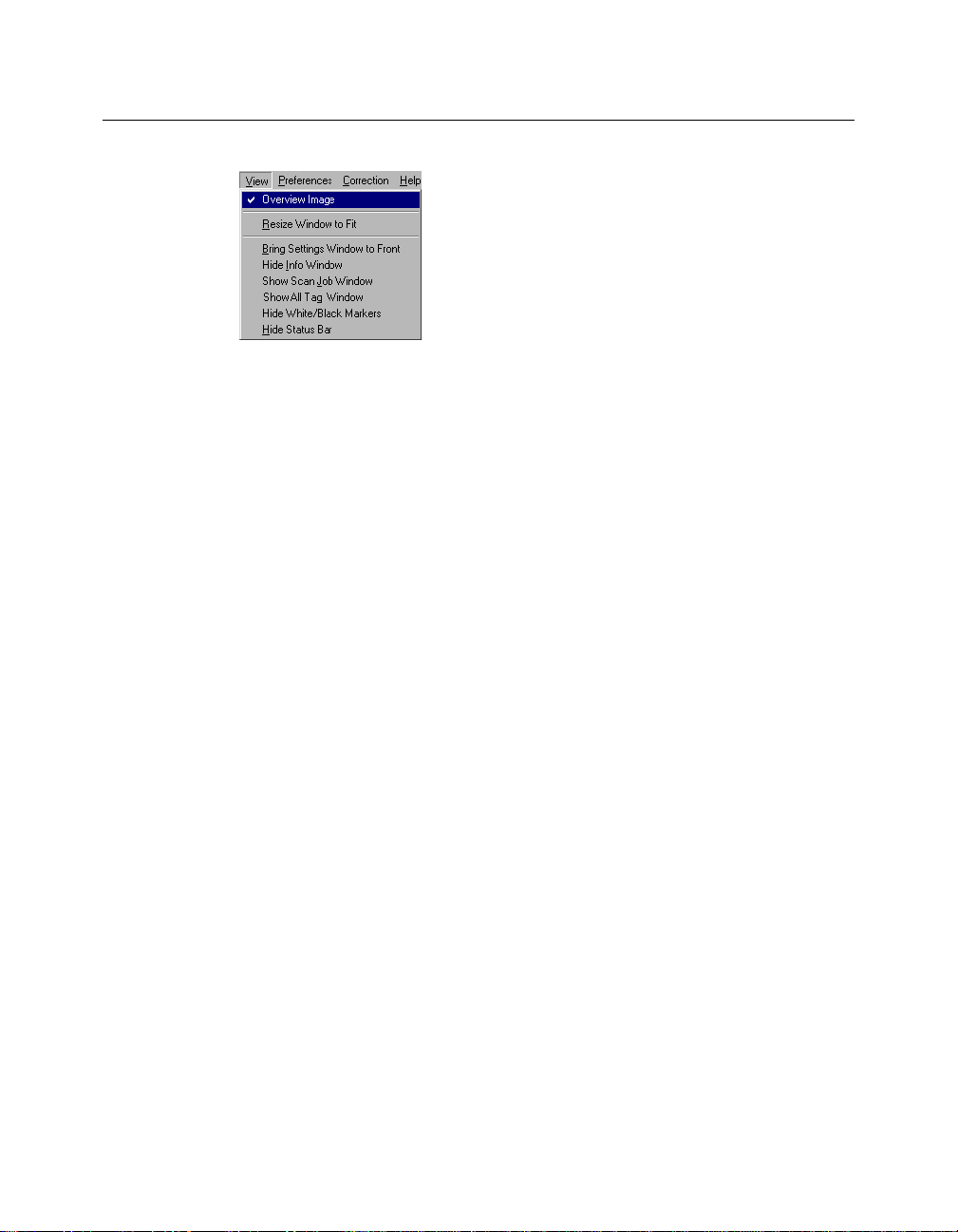
The View Menu
The View menu lets you:
• Get an overview or prescan view of an image
• Resize the Preview window
• Show or hide the Information and Scan Job windows
• Show or hide Status Bar
Overview Image
This command switches to Overview mode, lets you view the Overview image
among the scan jobs.
The Overview is a preview of your image as defined by the parameters set in the
Overview Setup command (in the Preferences menu). For instance, if your image
is 8" x 5" but the dimensions in the Overview Setup are 4" x 3", your overview
will be 4" x 3".
The maximum size of the Overview varies, depending on your scanner model.
For example, if the scan bed (the glass surface) of your scanner has a maximum
size of 8.5" x 11", the maximum Overview will be limited to those dimensions.
The size of the Overview can be changed by setting new dimensions in the
Overview Setup command. The new dimensions will take effect, however, only
with the next Overview. This means you need to click on the Overview button so
that the scanner does a new Overview; only then will you see the new
dimensions of the Overview.
Reference: The Preview window 11
Page 20
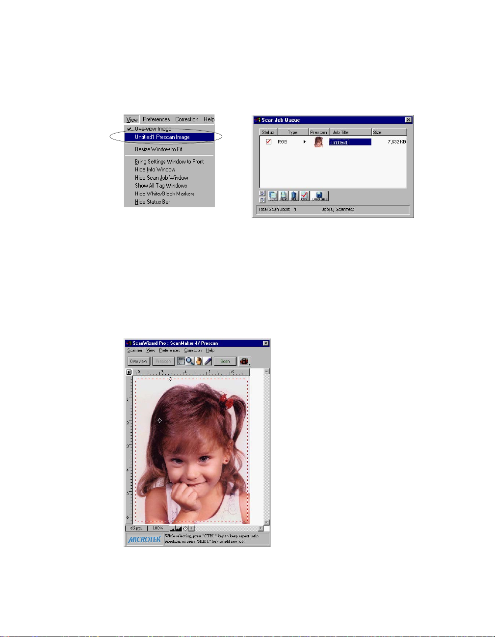
Prescan Image
By default, the Prescan Image Command does not exist, unless you press the
Prescan button. Each prescan image belongs to the respective scan job.
In the above screen, the Untitled 1 Prescan Image is resulted ever since you
clicked the Prescan button for a scan job named Untitled 1
When you select the prescan image item (e.g., Untitled 1 Prescan Image), the
preview window switches to the Prescan mode.
12 Microtek ScanWizard Pro for Windows
Page 21
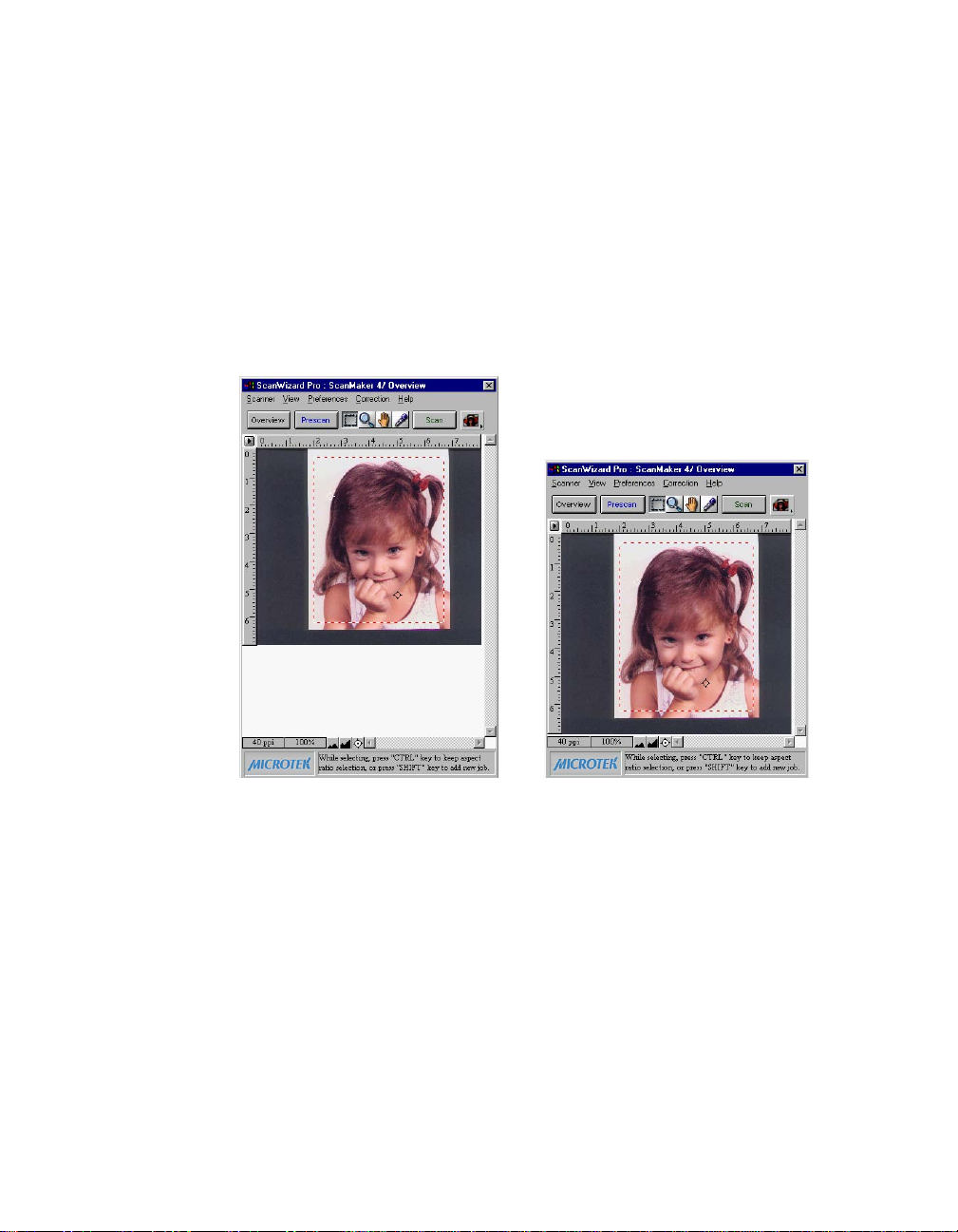
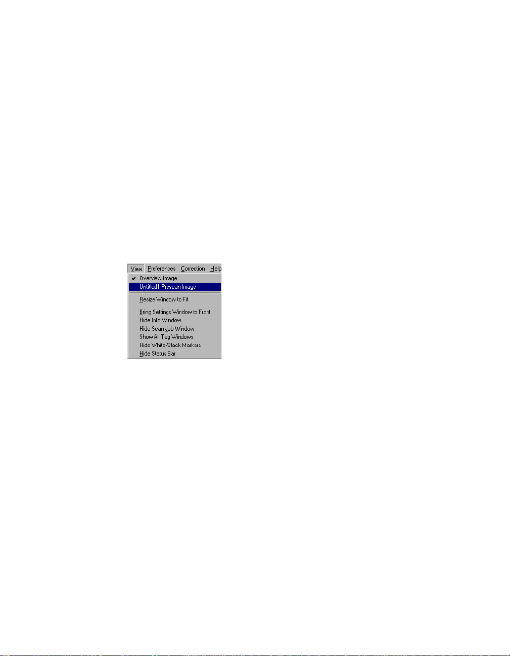
Resize Window to Fit
This command adjusts the Preview window to fit the Overview area.
In the example below, the Preview window is larger than the Overview area, as
denoted by the empty space below the vertical ruler. In other instances, the
Preview window may also exceed the Overview area if you manually enlarged
the Preview window (by dragging on the resize box).
To utilize window space more efficiently, use this command to resize the
Preview window.
Before resizing After resizing
To use this feature:
Choose the command Resize Window to Fit in the View menu or enter “Ctrl+r”
key.
This command is available only if the current zoom level is 100%, and is disabled
if zoom is set to other levels.
Reference: The Preview window 13
Page 22
Bring Settings Window to Front
This command brings the Settings window to the forefront, which is useful if you
have the Settings window hidden behind other windows or if you have a
expanded your Preview window such that it covers the Settings window.
Show/Hide commands
These commands allow you to switch between showing or hiding the Scan Job,
Information windows, Tag window, White/Black Markers, and Status Bar on your
screen.
To use this feature, choose the correct command from the View menu for
viewing a window. When the window appears, you can hide it by choosing the
particular Hide command for it.
Show/Hide All Tag Windows
When you click any location on the preview image, the Information window will
display a tag window to show the information of the clicked pixel color. You may
choose to hide All Tag Windows, if the tag information is of no use to you.
Show/Hide White/Black Markers
This command allows you to show or hide the White and Black Markers in the
Preview window. By default, the White and Black Markers are shown in the form
of a circular cross bar. A white circle in the middle represents the black marker,
and a black circle in the middle represents the white marker.
14 Microtek ScanWizard Pro for Windows
Page 23
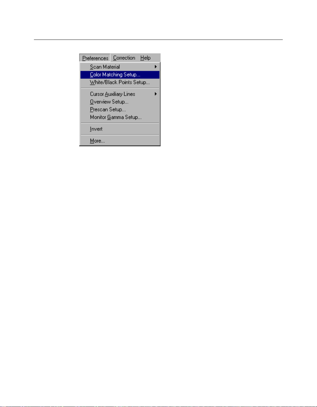
The Preferences Menu
The Preferences menu lets you:
• Choose the correct scan material
• Set up color matching system
• Set up White/black point parameters
• Hide/show auxiliary cursor lines
• Set up Overview mode parameters
• Set up Prescan mode parameters
• Fine-tune monitor gamma values
• Invert images on the screen
• Further settings
Reference: The Preview Window 15
Page 24
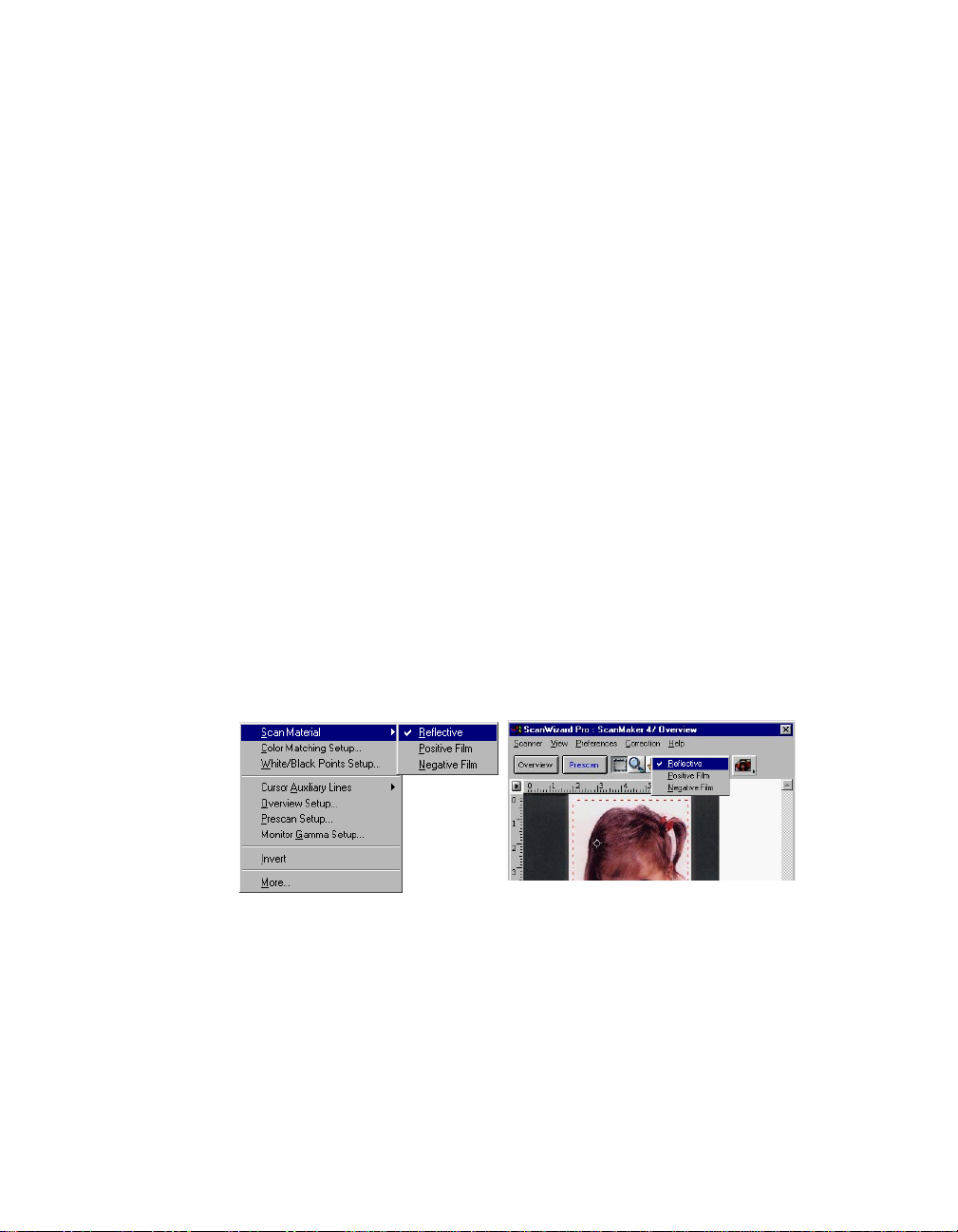
Scan Material
This command allows you to select the correct scan material. Scan materials can
be classified into three types:
• Reflectives, such as photographs or prints.
• Positives, such as slides.
• Negatives, such as the negative film you use for your camera.
The default scan material depends upon the scanner you're using, and the
choices available to you in the Scan Material submenu will also depend on your
equipment.
For instance, the positive option appears only if you're using a Transparent
Media Adapter (TMA) with your scanner. Some scanners, such as ScanMaker 5
and ScanMaker 2000, include a built-in TMA.
If you are scanning negatives or positives, make sure you specify the correct
scan material, or you will get inaccurate scanning results.
To use the scan material feature:
Choose the Scan Material command in the Preferences menu. From the submenu
that appears, select your scan material; a check will appear next to the selected
option. The selected option will also be shown in the Scan Material Status icon
(discussed below).
Note: If your Preview window is close to the right edge of your monitor, the Scan
Material submenu may appear on the left side instead of on the right (as shown above).
To resolve this, move the Preview window towards the left to create enough room for the
submenu to drop down on the right.
16 Microtek ScanWizard Pro for Windows
Page 25
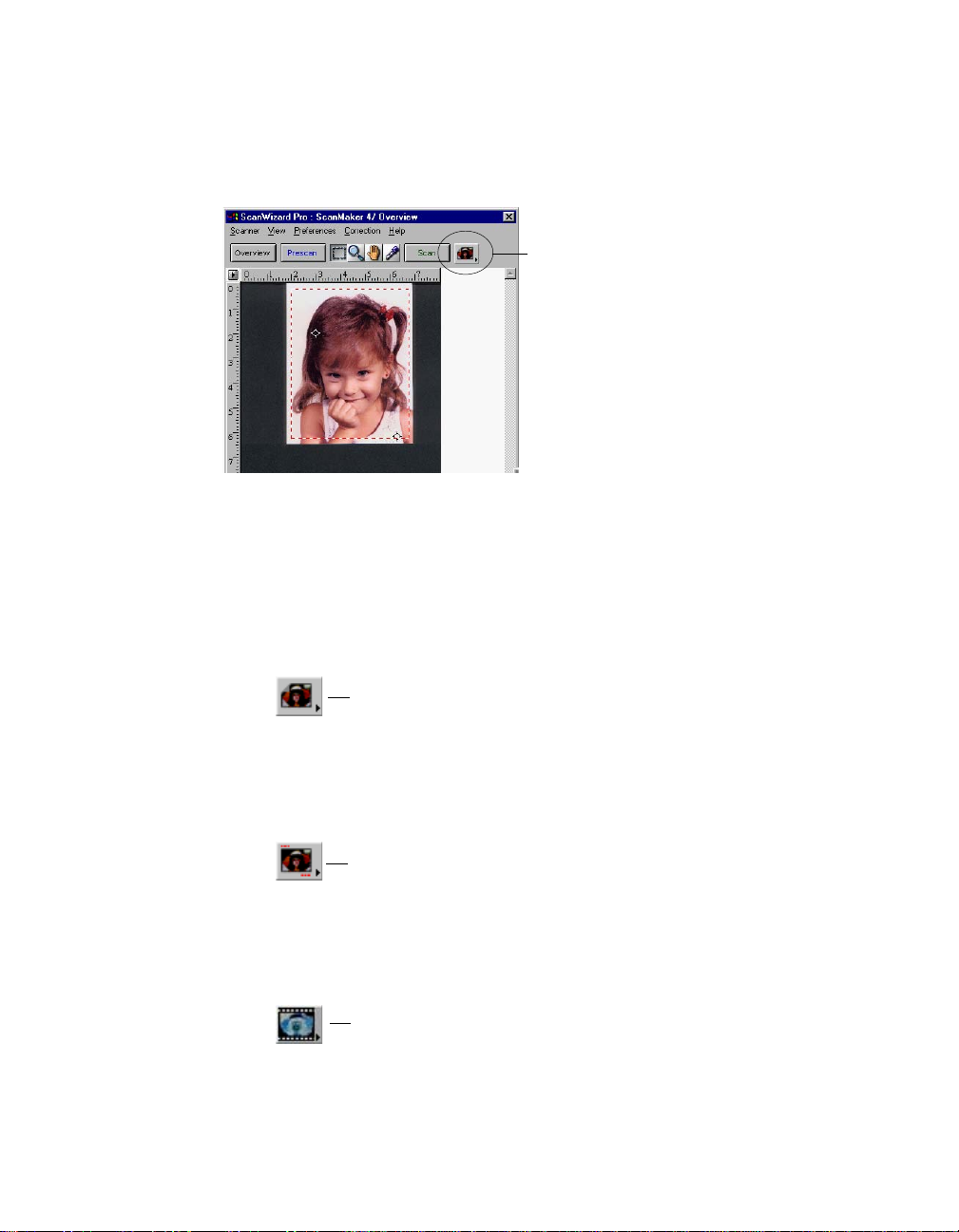
The Scan Material Status icon
Another way to access the Scan Material menu is to use the Scan Material Status
icon, located to the right of the Scan button.
Scan Material Status icon
The appearance of the Scan Material icon changes, depending on whether your
scan material is reflective, positive, or negative.
• If you're scanning a reflective (such as a photo or print), this icon will
appear in its normal form like an ordinary icon. When you click on the icon
and hold down the mouse, you'll see the Reflective option checked.
Appearance of the Scan Material Status icon when scanning
reflective materials.
• If you're scanning a positive transparency or filmstrip, this icon will appear
in the form of a positive. When you click on the icon and hold down the
mouse, you'll see the Positive Film option checked.
Appearance of the Scan Material Status icon when scanning a
positive transparency or filmstrip. Notice the perforations on the
top and bottom of the icon (characteristic of slides) to distinguish it
from the reflective icon.
• If you're scanning a negative transparency or filmstrip, this icon will appear
in the form of a negative. When you click on the icon and hold down the
mouse, you'll see the Negative Film option checked.
Appearance of the Scan Material Status icon when
scanning a negative transparency or filmstrip.
Reference: The Preview Window 17
Page 26
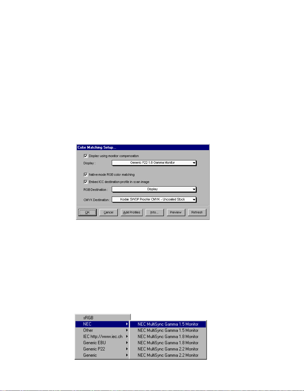
Color Matching Setup
To keep color consistency between the scanner, monitor, and printing device,
ScanWizard Pro applies Kodak CMS (Color management system) with ICC
(International Color Consortium) profile standards. For more information on
Color Management System, see Appendix.
Color Matching Set Up command lets you select the correct ICC profile for
matching with your color monitor and color printer.
When you install ScanWizard Pro, the CMS installer will prompt you to match
your color monitor and printer with the provided list. You may, however, change
and update your existing settings from this command. The default profile for
color monitor is “Generic P22 1.8 Gamma Monitor” and printer will set to
“Display”.
Display using monitor compensation
This option controls how the RGB destination data will be displayed. If this
option is unchecked, the RGB data is displayed directly to the monitor. If
checked, RGB destination data will be compensated to the selected monitor type
before it is displayed on the monitor.
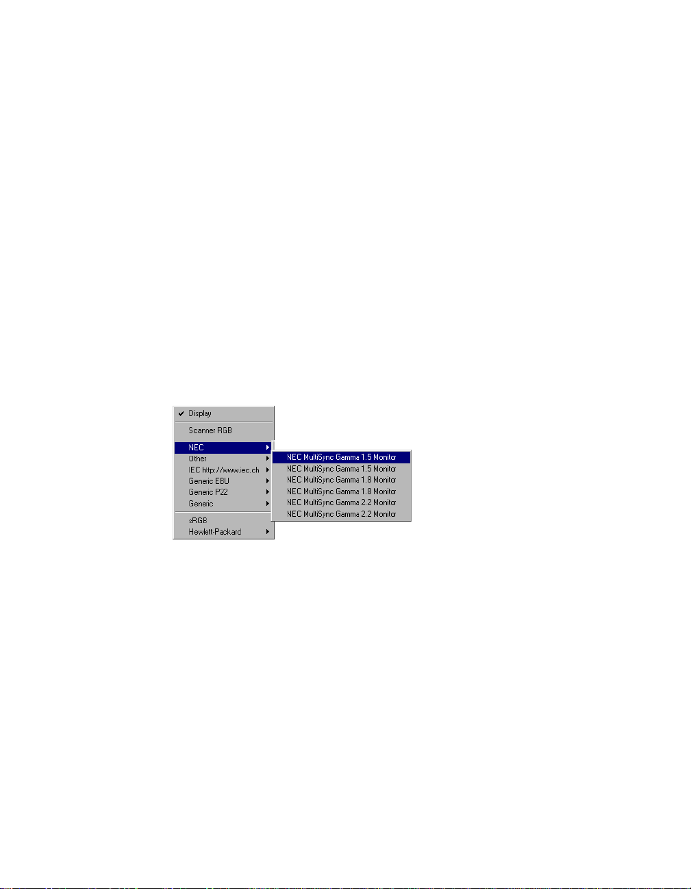
Display
This feature allows you select color monitor type that is used for displaying RGB
data. The monitor profile will be applied only when “Display using monitor
compensation” option is checked.
18 Microtek ScanWizard Pro for Windows
Note: If the available
monitor types do not
include the one you
have, select Generic P22
or Generic EBU. These
two profiles are suitable
for most of the monitors.
Page 27
Native mode RGB colo
rr
r matching (Native Color Mode only)
rr
If unchecked, the ICC profile only applies to the RGB color for matching without
applying to other output devices (e.g., printer or image typesetter). If checked
the ICC profile applies to both the color monitor and output devices.
This check box should generally be checked unless you want to scan raw color
data, in which case you lose the compensatory effects of the Color Matching
system. Also note that it is not desirable to scan in raw data and then perform
data conversion, which will not generate the correct CMS effect.
Embed ICC destination profile in scan image
If checked, the ICC information is saved into the image file. This option is useful
especially for image application software, such as Photoshop.
RGB Destination
This feature lets you select the RGB output device (e.g., display monitor, or RGBbased printer) for matching RGB Color family images (including RGB colors, 48bit RGB colors, and 256 colors image types).
A number of RGB profiles is supplied by ScanWizard Pro. If you do not see the
ICC profile for your monitor or RGB device, contact your device manufacturer.
To add a specific ICC profile, click “Add Profiles” button to load it from the
floppy disk or CD-ROM that contains the ICC profile. Some device suppliers
(e.g., Kodak) have placed the ICC profiles in their web site. You may require to
download the ICC profile from their web sites.
Reference: The Preview Window 19
Page 28
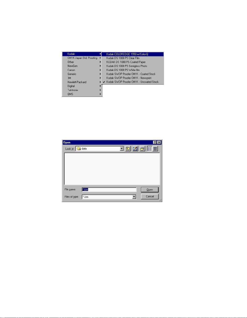
CMYK Destination
If your image type is CMYK color, this function lets you select the CMYK based
color printer or commercial offset printing standards for color separation.
Add Profiles
This command allows you add additional ICC profiles normally came with your
device (e.g., display monitor or printer).
Select the profiles you need, then click on the Open button to load the profiles
to ScanWizard Pro. This process takes a while for initialization.
Note: When you purchase color monitor or color printer, check to make sure your
supplier provides the corresponding ICC profiles.
20 Microtek ScanWizard Pro for Windows
Page 29
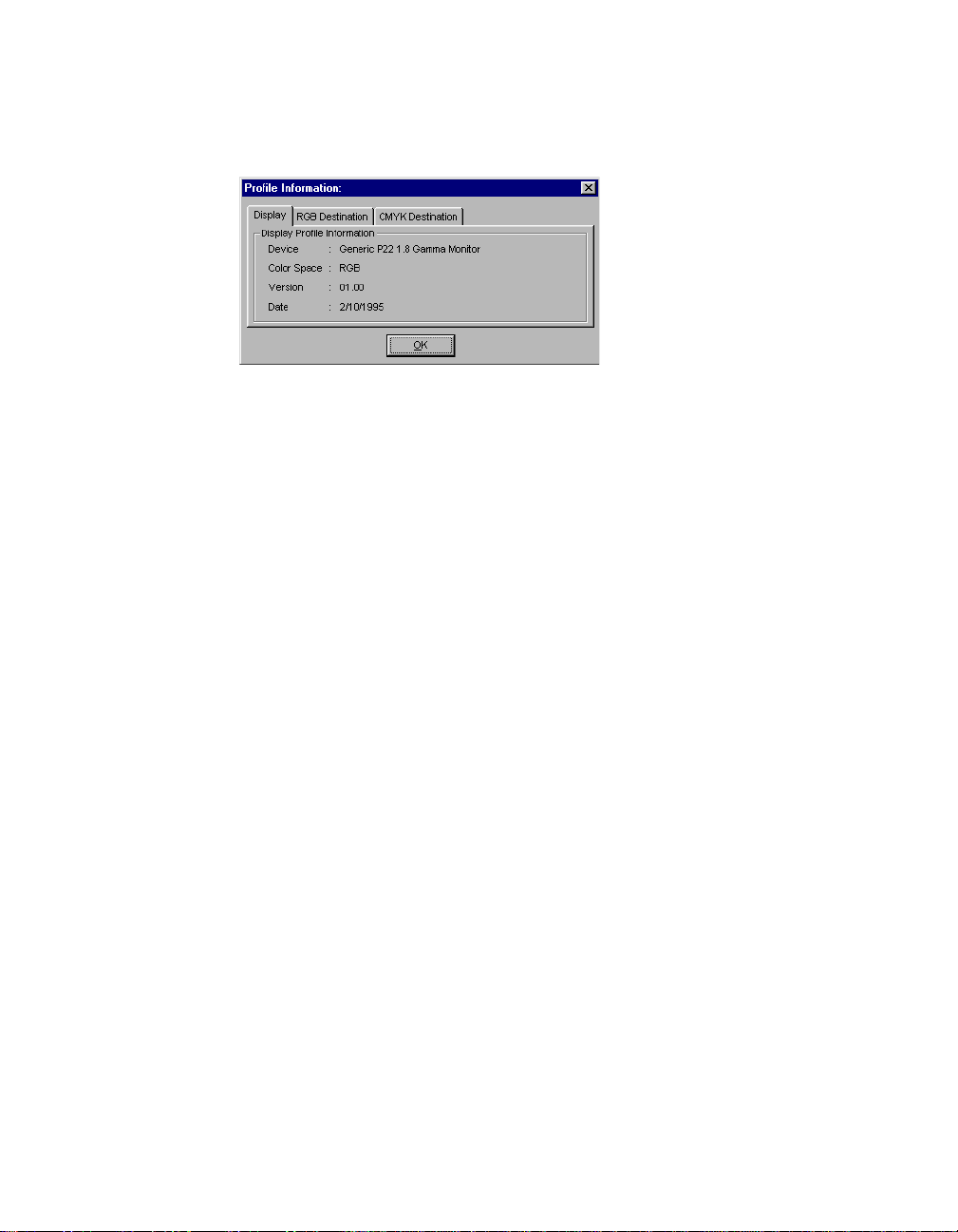
Info
This command displays basic profile information for the current selected devices
Preview
Clicking on the Preview button immediately updates the Preview window image
when a new color profile is selected. This will reflect colors consistent with the
newly selected profile.
Refresh
Clicking on the Refresh button updates the ICC profiles that have been stored in
\Windows\System\ color and \Windows\System32\color folder.
Reference: The Preview Window 21
Page 30
White/Black Points Setup
White point is a reference point that specifies the lightest area in an image,
making other areas to be adjusted accordingly. Likewise, black point is the
darkest reference area.
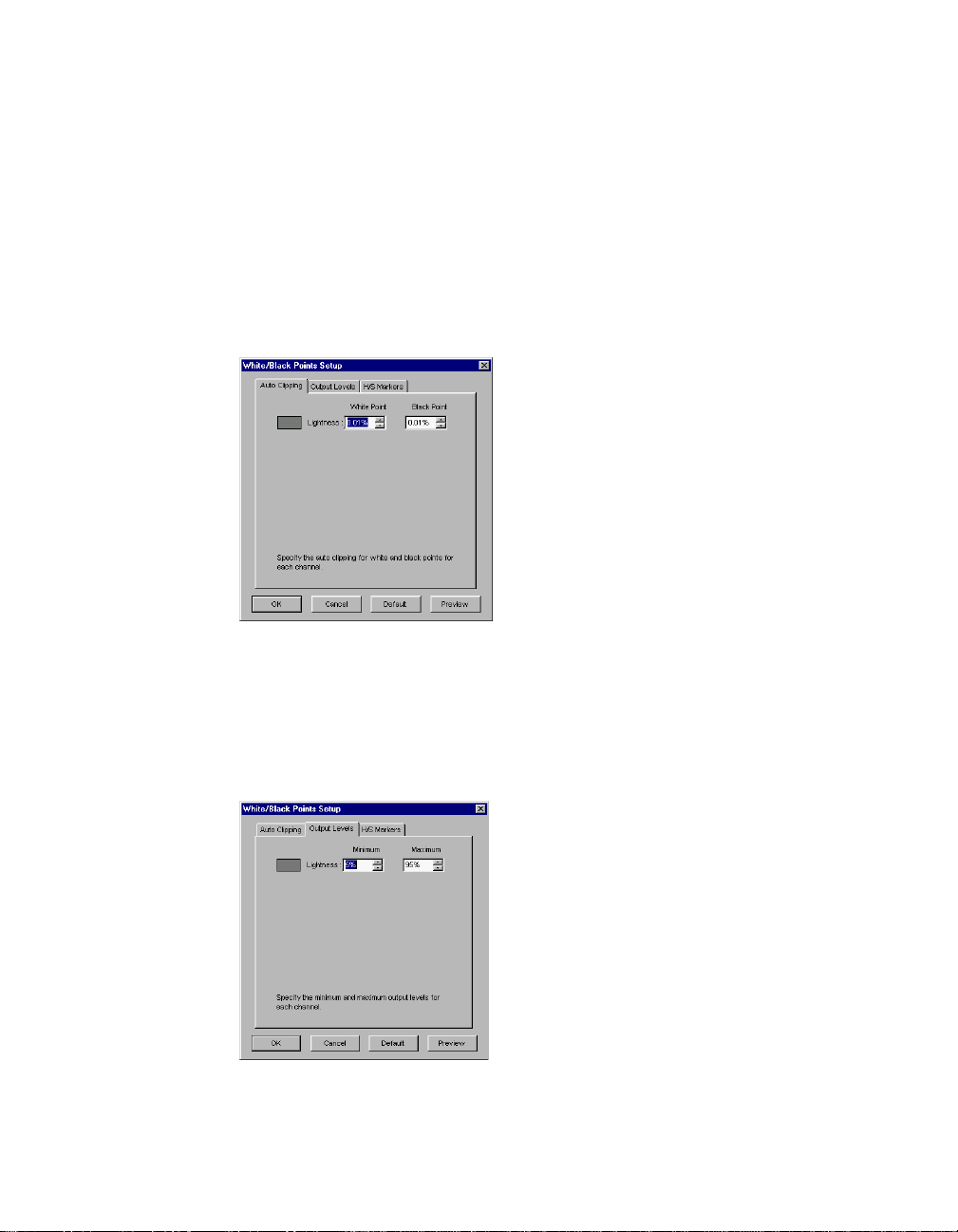
Auto Clipping
Auto white point clipping: For the lightness channel, you can assign black or
white level for clipping. To the White Point, colors under the percentage you
assigned are mapped to white; similar situation can be applied to the Black Point.
Output Levels
Minimum output level: For the lightness channel, you can assign minimum or
maximum level for clipping. To the Minimum level, colors under the percentage
you assigned are cropped out; similar situation can be applied to the Minimum
level.
22 Microtek ScanWizard Pro for Windows
Page 31

H/S Markers
Let’s you set the Highlight level (shown as a black circle) and Shadow level
(shown as a white circle). You can specify the range of the Highlight/shadow
markers to either the entire preview (selecting the “Overview or Preview image”
option) or only within the scan frame (selecting the “Current Scan Frame”).
In the White/Black Points Setup window, clicking the “Preview” button will get
instant result; clicking the “OK” button will exit from the Setup window and
apply the H/S markers setting you have made to the preview image.
Reference: The Preview Window 23
Page 32

Cursor Auxiliary Lines
This command allows you to create horizontal and vertical grid lines with your
cursor to help define a scan frame precisely. Using the grid lines, you can also
read the measurements off your ruler more easily.
Cursor auxiliary lines on the
x and y axis
To use this feature:
1. Choose the Cursor Auxiliary Lines command in the Preferences menu. From
the submenu that appears, select how the cursor lines will appear.
• On both x (horizontal) and y (vertical) axes
• On x axis only
• On y axis only
• None (no cursor lines)
Note: If your Preview window is close to the right edge of your monitor, the Cursor
Auxiliary Lines submenu may appear on the left side instead of on the right (as shown
above). To resolve this, move the Preview window towards the left to create enough room
for the submenu to drop down on the right.
24 Microtek ScanWizard Pro for Windows
Page 33

2. Click on the Frame tool.
To see how the cursor lines work, draw a scan frame. Click on the top left
corner of the image as your starting point, then drag down to form a scan
frame.
As you draw the scan frame, cursor lines will appear to help you draw the
scan frame precisely.
When you release the mouse, your scan frame will be aligned with the
cursor lines.
Click on the Frame tool, then
define a starting point.
Cursor lines appear to the
top and left of the image.
As you drag the mouse down,
the scan frame is aligned with
cursor lines on the x and y
axis (based on your selected
option in the submenu).
Reference: The Preview Window 25
Page 34

Overview Setup
Specifies overview scanning speed options and the overview area for executing
the Overview command.
Overview Area
Choose Maximum Size, other fixed dimensions, or choose Custom Size then
enter the required dimensions. You may also set the Overview Area by dragging
the dotted boarders.
Unit
Lets you set the ruler units such as inch, cm, and mm.
26 Microtek ScanWizard Pro for Windows
Page 35

Fast Overview
The Fast option supports faster scanning with the sacrifice of overview image
quality; on the contrary, if Fast Overview is unchecked, Overview scanning
speed is slow, but it obtains better overview image quality.
Overview automatically when ScanWizard Pro is started
If this option is checked, when ScanWizard Pro is launched, your scanner
automatically performs prescan, and shows the prescanned image in the preview
window. If unchecked, auto-preview is disabled, you should click the Overview
button to execute prescan.
Keep Overview image
If unchecked, the preview image will be cleared when you exit from ScanWizard
Pro and re-launch ScanWizard pro. If checked, the preview image stays on the
screen unless subsequent overview or prescan is performed.
Show confirmation message box if there is any prescan image
If this option is checked, a confirmation message appears, notifying you in the
preview window, a previously prescanned image exists. If unchecked, there is no
warning message in this occasion.
Preview
Click this button to get a scanning preview.
Reference: The Preview Window 27
Page 36

Prescan Setup
This command allows you to set the parameters of scanning a prescan image.
Major difference between Overview and Prescan is, Overview button scans the
area specified in the Overview Setup command getting a low resolution preview
image; where Prescan button only scans the selected scanning frame, resulting a
more detailed preview image. When the Prescan Setup dialog box (below) comes
up, click on the option you need or specify your parameters.
Fast Prescan
If checked, you get an coarse image at a faster scanning speed; if unchecked,
you get a quality image with the sacrifice of scanning speed.
Keep All prescan images
If unchecked, all of the preview images will be cleared when you exit from
ScanWizard Pro and re-launch ScanWizard pro. If checked, the preview images
stay on the screen unless subsequent overview or prescan is performed.
Prescan Image Margin
This option allows you to specify margin around the scan job in the first place,
subsequently you can adjust the scan frame slightly in the Prescan mode.
Available options are: None, Small, Medium (default), and Large.
Prescan Image Dimension
This option allows you to specify the size of the prescan image. Available options
are: Full screen, 75% screen, 50% screen, and Fit Preview Window. Size of the
Prescan image is not necessarily to fit into the specified option, it only is based
on the height/width ratio to get the maximum covered area.
Background Prescan
If checked, the background prescan function is enabled. You can assign a
number of scan jobs to execute prescan, in the mean time, carrying out other
jobs. If unchecked, this function is disabled.
28 Microtek ScanWizard Pro for Windows
Page 37

Monitor Gamma Setup
The Monitor Gamma Setup command lets you compensate linear intensity of the
monitor, making them consistent between preview image and the final scanned
image.
Monitor Gamma
Check this box to enable monitor gamma value setting.
When the monitor gamma option is checked, click the up/down arrow buttons,
making gray-level of the two boxes as close as possible. Click OK to confirm.
Reference: The Preview Window 29
Page 38

Invert
This command creates a negative of an image. The Invert effect is applied to all
scan jobs, not just the selected scan job.
When an image is inverted, the brightness value of each pixel is converted to the
inverse value on the 256-step color values scale. For example, a pixel in a
positive image with a value of 255 is changed to 0, and a pixel with a value of 5 is
changed to 250.
To use this feature:
Choose the Invert command in the Preferences menu. A check appears next to
the command when it is enabled.
30 Microtek ScanWizard Pro for Windows
InvertOriginal
Page 39

More command
The More command lets you specify less-frequently used, miscellaneous
parameters.
Smoked Glass Background
This command helps you distinguish the current scan frame from the rest of the
preview image for greater visibility of the current scan frame.
With the Smoked Glass feature turned on, the part of the image within the
current scan frame will stand out, while the rest of the image (the “irrelevant”
material) is relegated to a background resembling smoked glass.
Current scan frame
(with pulsing lines)
Part of image not in
any scan frame and
also hidden by smoked
glass background
Reference: The Preview Window 31
Page 40

Confirmation Message
If checked, a confirmation message appears when you set image effect functions
such as Rotate or Flip. If unchecked, the message does not appear.
If checked, the image that is prescanned in the overview command remains on
the screen until another image acquisition is performed. If unchecked, the
overview image is deleted when you exit from ScanWizard Pro.
Color Space Mode
If LCH mode is selected, the color space is represented by Lightness, Chroma
(saturation), and Hue. If Native mode is selected, color enhancements are
performed in RGB, CMYK or Lab.
Scan Mode
During scan, you have these selections: Speed, Quality, and Best Quality.
The following selections are available as scan modes:
Speed Higher scanning speed results in lower image quality.
Quality With this option, the scan head remains stationary while the
CCD is being exposed to light source, resulting in better
images. Most scan materials can obtain a “quality” scan if this
mode is chosen.
Best Quality This option is available for 10-, 12- or 16-bit scanners only.
The CCD exposure scheme is similar to that in the “Quality”
option, but image correction is first applied on the 10- or 12bit image, then converted to an 8-bit image. RGB Colors (48bit) image is always scanned in Best Quality option regardless
of any other option is selected. This option is useful for
scanning originals that have deteriorated in quality and for
performing image correction on them without losing detail.
Note: RGB color images are always scanned in the Best Quality mode, regardless of the
scan mode option selected.
32 Microtek ScanWizard Pro for Windows
Page 41

Best Quality: Multiple Sampling
This feature is only implemented on high-end scanner models. If your scanner
does not support this function, no sampling lines are available for choosing.
The Multiple Sampling function allows your scanner to perform multiple scans
on each line, and then converts their average results into one line. This scheme
reduces image noise while increasing the dynamic range of the scanner.
To use this function, select Best Quality in the Scan Mode option, and in the
submenu, choose the sampling lines you need. Your selection will be used for the
final scan. Available sampling lines are 2, 4, 8, and 16; choose None if multiple
sampling is not required. The greater the number of sampling lines chosen, the
greater the amount of image data being processed. A trade-off occurs, however,
between sampling and speed, and the higher the number of sampling lines, the
slower the scanning time.
Interpolation Mode
This command is used when the output resolution of the scanned image does
not match the resolution at which the image is scanned. To compensate for the
deviation, ScanWizard Pro performs interpolation. Available options are
“Nearest neighbor (speed)” and “Bilinear (quality)”. The Speed option supports
scanning and yields images at fair quality. The Quality option takes a longer
scanning time but produces images of finer quality comparable to those
obtained from Adobe Photoshop's bi-linear interpolation mode.
Working Directory
This command lets you place to store temporary working files (e.g., scan job
files) during ScanWizard Pro's session. If the directory you specify is not found
or does not exist, a warning message appears, and ScanWizard Pro will create a
new one for it.
If the computer on which the working
directory is created is being shared for use
among several people, each person may
specify a working directory of their own.
Reference: The Preview Window 33
Page 42

The Help Menu
The Help menu lets you access on-line help for ScanWizard Pro for Windows.
The Help menu uses standard Windows conventions for obtaining on-line help.
If you are not familiar with this procedure, refer to your Microsoft Windows
user's guide.
About
This command gives you information on the ScanWizard Pro for Windows
scanning software. ScanWizard Pro for Windows is also referred to in the About
screen as the ScanWizard Pro scanner controller.
34 Microtek ScanWizard Pro for Windows
Page 43

The Tool Buttons
Frame
Magnify Glass
Pane
Dropper
Reference: The Preview Window 35
Page 44

Scan Frame tool
The Frame tool lets you create a scan frame or multiple scan frames in the
preview image, which is the active area on which controls and commands can
be applied.
The Frame tool can also be used to create multiple scan frames, but only one
can be current at a time; the current scan frame is indicated by a marquee
(marching ants, or dotted boarders). The current scan frame can be more easily
distinguished if you turn on the Smoked Glass Background command (in the
Preferences menu).
Image with single scan frame
Current scan frame is denoted
by marquee
Another scan frames,
which can be
distinguished by the
marquee around the
right half of the image.
This is not the current
scan frame, however, as
the part of the image
enclosed by the scan
frame is dimmed.
Smoked Glass
Background is on so that
the current scan frames
can be seen more
clearly.
36 Microtek ScanWizard Pro for Windows
Image with multiple scan frames
Current
scan frame
Page 45

Scan Frame Keyboard Shortcuts
To get a better controls of scan frame settings, use Ctrl and Shift keys on your
keyboard.
Ctrl key Holding down the Ctrl key and drag the
marquee results a square selection.
Shift key Holding down the Shift key and drag the
marquee generates a new frame for a scan job.
A more detailed table is listed below.
Function Keys Result
Move/Resize click+move Move scan frame.
Change Job click+move Change to the current job.
Redraw/Add click+drag Redraw current frame.
Prescan double-click Change to the Prescan mode and set the
click+drag Resize scan frame.
Ctrl+click+drag Toggle between “Keep Square” and “resize”.
click+drag Select the job and set it to the current job.
Ctrl+click Toggle between “Job selection” and
“make it as the current job”.
Ctrl+click+drag Redraw current frame square.
Shift+click+drag Add new job.
Ctrl+Shift+click+drag Add new job in a square boundary.
job as current.
Reference: The Preview Window 37
Page 46

To use the Frame tool:
1. Click on the Frame tool.
2. Move the pointer (now a crossbar) to the preview image, and draw a frame
enclosing the area to be selected. When you release the mouse, the scan
frame will be in a marquee.
To make multiple scan frames (which would add scan jobs), hold down the
Shift key and drag the mouse. For more information on scan jobs, refer to
the Scan Job section of the Reference.
3. To resize the scan frame, do either of the following:
• Move the cursor to any corner of the frame; the pointer will change to
a double-headed arrow. Hold down the mouse, and drag to form a new
area, then release the mouse; or
• Click on the Frame tool again and restart the area-selection process.
38 Microtek ScanWizard Pro for Windows
Page 47

Magnify Glass tool
The Magnify Glass tool enlarges your view of the preview image, allowing you to
set the scan frame with greater precision if you need to. Only your view of the
preview image is changed; the actual size of the image remains unaffected.
Each click of the Magnify Glass tool magnifies or reduces by a factor of 2. Thus,
the magnification levels increase from 100% to 200%, to 400%, and to the
maximum 800%.
Original image view
Image view enlarged with
Magnify Glass tool
To enlarge the view:
1. Click on the Magnify Glass tool.
2. Place the pointer — now a lens with a plus sign inside it — on the image
and click.
To reduce the view, hold down the Shift key and click again. The plus sign
changes to a minus sign when you hold down the Shift key.
Reference: The Preview Window 39
Page 48

Pane tool
The Pane tool lets you scroll through a preview image, allowing you to move
parts of the image into view.
The Pane tool can be used for zoomed-in images (enlarged through the Magnify
Glass tool), or images not included completely within the frame of the preview
window (for instance, if your preview image is 7 inches wide and you resized
the width of your overview/preview window to only 3 inches).
Scrolled imageZoomed-in image
To use the Pane tool:
1. Click on the Pane tool.
2. Move the pointer (now a hand) to the image. Hold down the mouse and
move the hand left, right, up, or down, and see portions of the image come
into view. You can also use the scroll bars to scroll through the image.
40 Microtek ScanWizard Pro for Windows
Page 49

Dropper tool
The Dropper tool creates tag windows for setting White and Black points. If in
LCH mode, Add/Remove Cast is present. When you click on the preview image,
the tag window instantly displays the pixel information.
The Dropper tool allows you to sample color from an area of an image, and to
designate a new white or black point. The two buttons let you select black and
white points for the current job. Using the same pair of tag windows, you can
apply black and white points to several jobs.
With the Dropper tool, you can determine the color values for any pixel in an
image. When you click on the Dropper tool and pass over a pixel, the value of
that pixel will be displayed in the Information window, based on the sample size
also selected in the Information window. Pixel-value information is useful
especially when you're making color adjustments based on color values.
To create a Tag window
The Tag window displays coordination (x, y) position and the pixel values
(RGB, CMYK, Lab, et. al.), depending on the image mode you select for the
current scan job. The tag contents are updated according to the current job
settings.
Reference: The Preview Window 41
Page 50

To close the Tag window
Clicking on the Close box closes the Tag window. To close all Tag windows,
holding down the Shift key, then click on any Close box.
Choosing Black and White Droppers
Holding down the Ctrl key enables the Black dropper. Holding down the Alt key
enables the White dropper.
Input display Mode switch
To change the input display (Native color or LCH color), click on the Mode
Changing triangle.
Black, White, and Color diamonds
The black (for the shadow) and white (for the highlight) diamonds are used to
apply the shadow and highlight points indicated on the Tag windows to the
image.
• To set the shadow point on the image to its Tag Windows value, click the
black diamond.
• To set the highlight point on the image to its Tag Windows value, click the
white diamond.
• The Color diamond: The color diamond is used to add or remove color cast
to the selected color. Remove color cast is the default, indicated by a minus
sign. To add color cast, click the title bar of the Tag Window, then hold
down the Alt key, the minus sign is changed to plus sign, than add the
color cast.
• Color display: The color strip shows the color selected by the Tag Windows
Tools
42 Microtek ScanWizard Pro for Windows
Page 51

Setting White/Black points
There are two ways to set White and Black points:
1) Choose it from the Tag window, and 2) choose it directly from the Dropper
(holding down the Ctrl key to select Black point, and the Alt key to select White
point).
To restore original settings:
Select “No Correction” from the White/Black points menu.
- or -
Click on the “Reset” button.
Before restore After restore
Reference: The Preview Window 43
Page 52

To change the sample size of the Dropper:
1. Open the Information window by choosing the Show Info Window
command in the View menu.
2. Click on the Sample Size button, located to the right of the RGB values in
the Information window.
3. Choose your options.
Select the sample size. For instance, the 1 by 1 option will display the value
of one pixel — the one in the middle of the Color Meter Display. The 3 X 3
option reads the average value of a 3-pixel by 3-pixel area.
To display color information for a pixel or an averaged area:
1. Click on the Dropper tool.
2. As you pass over a point in the image, see the Information Window — the
RGB, CMYK, or Lab values will be displayed in the Color Meter Display.
These values are in turn based on the sample size you selected.
Dropper Keyboard Shortcuts
To get a better controls of scan frame settings, use Ctrl and Shift keys on your
keyboard.
Key Function
Click Clicking on the preview image generates a Tag window.
Ctrl key Holding down the Ctrl key, the Dropper tool becomes a
Alt key Holding down the Alt key, the Dropper tool becomes a
44 Microtek ScanWizard Pro for Windows
Black Point
White Point
tool.
tool.
Page 53

Action Buttons
The Overview button scans a low resolution preview at a size
specified in the Overview Setup command.
The Prescan button performs high resolution preview for the
selected scan jobs.
The Scan button lets you scan the image in your scanner and
delivers it to your image-editing software. The scanned image
is based on the specifications you have chosen in the Settings
window and on controls you may have applied to the preview
image if a preview was performed.
If you bring up ScanWizard Pro directly without using other
application program, the Scan button turns out to be Batch
button, and you are in the Batch scanning mode. In this mode,
you can scan multiple jobs in a single pass.
Reference: The Preview Window 45
Page 54

Rulers
The rulers on both sides of the preview window help you with operations that
need precise measurement and alignment of your image.
The unit of measurement in the rulers is determined by the unit of
measurement you have selected. This can be done either in the Image
Dimension controls, located in the Settings window, or by clicking on the ruler
unit button at the 0,0 point of the rulers in the Preview window.
Depending on your chosen unit of measurement, the rulers can mark off
measurement in these units: inch, centimeter, millimeter, point, and pixel. The
pixel option is dimmed if the selected resolution unit is lpi, and vice versa.
Pressing the ruler unit
button displays the
measurement menu.
Select the unit of measurement for the rulers in
either the Settings window or the Preview window.
To select the unit of measurement for the rulers:
Click on the unit box in the Settings window, or click on the ruler unit button
at the 0,0 point of the rulers in the Preview window. When the submenu
appears, select the unit of measurement.
46 Microtek ScanWizard Pro for Windows
Page 55

Preview Area
The preview area is where the preview image appears.
The dimension of the preview area varies, depending on your scanner model.
The size can be changed, however, through the Overview Setup command in the
Preferences menu. You can increase the size of the preview area to see more
detail in your image, or you can reduce the preview area to save on memory.
For details on how to change the size of the preview area, refer to the Overview
Setup command in the Preferences menu section.
Preview area
Reference: The Preview Window 47
Page 56

Auxiliary information
Preview image
resolution
Zoom scale
Zoom-out
PP
review image resolutionreview image resolution
P
review image resolution:
PP
review image resolutionreview image resolution
Flash Markers
Zoom-in
When Overview or Prescan command is executed, the preview window displays
the prescan image, also the auxiliary information shows the preview image
resolution. Preview image resolution is changed according to the size of the
preview window. To resize preview window, drag any side or corner of the
window.
Zoom scale
Lets you choose the size of the preview image, ranging from 100%, 200%, 400%
to 800%.
Zoom-out
Each time you click on this zoom-out icon, the preview image is reduced one
zoom scale level, minimum 100%.
Zoom-inZoom-in
Zoom-in
Zoom-inZoom-in
Each time you click on this zoom-in icon, the preview image is enlarged one
zoom scale level, maximum 800%.
White/Dark points marker flasher
When preview image is displayed, the white point marker (the extremely white
reference point) and the dark point marker (the extremely black reference
point) are shown. Sometimes the two markers cannot be visually detected,
clicking on the White/Dark points marker flasher activates the markers to flash
5 times. When they flash, the locations can be seen.
48 Microtek ScanWizard Pro for Windows
Page 57

The Settings Window
The Settings window contains the parameters for outputting your scanned
image for the current scan job and includes the advanced image correction tools
of the program.
Elements of the Settings window
Resolution edit
box: Lets you enter
a resolution value in
which your image will
be output (not
scanned).
Image Dimension
controls: include
various parameters
for specifying scan
frame width and
height, scaling,
output width and
height, and unit of
measurement.
Type menu: Lets you
select the image type in
which your image will be
scanned and
processed.
Unit selection: Lets
you choose the unit of
measurement for
resolution in either ppi
(pixel per inch) or lpi
(lines per inch).
Advanced Image
Correction tools:
Improve image quality
by enhancing image
characteristics such as
brightness and contrast,
white and black points,
and others.
Reference: The Settings Window 49
Page 58

Output Image Parameters
The Output Image Parameters include the various controls that determine how
your image is scanned and processed.
The Output Image Parameters include:
• Type
• Resolution
• Unit Selection
• Image Dimension controls
Type (Image Type or Scan Mode)
The Type menu determines what your resulting scan will be. It does not refer to
the original image mode. For instance, if you have a color photo but choose 256
grayscale for the scan mode, the photo is scanned and processed as grayscale.
To use the Type menu, from the Type menu, select your scan mode. Choose the
correct image type, as the wrong choice will simply create bigger files that won't
be of any use to you.
• If you have a grayscale original, do not set image type to RGB Colors (48-bit).
RGB colors are 24-bit, and RGB (48-bit) colors are used for applications
such as Photoshop 5.0.
Note: The options of RGB Colors (48-bit) and Gray Scale (16-bit) are available
only for 36-bit or above scanners, such as ScanMaker 5. Only a few applications
(e.g., Photoshop 5.0) in the market today support these two options.
50 Microtek ScanWizard Pro for Windows
Page 59

• CMYK color separation is used for commercial printing. Some image editing
software program, such as Photoshop 5.0 full version, have the capability of
processing CMYK file format. ScanWizard Pro CMYK color supports US
SWOP, European, and Japanese printing ink standards. For more information, refer to Appendix C.
• Web/Internet color is 256-indexed color image converted with uniform
palette and error diffusion. The sRGB (web color standards) profile is used
for color matching with this image type.
• Customized 256 color option lets you select the attributes of indexed color.
If this option is selected, the following dialog box displayed.
Palette
Lets you choose the method of creating
color palette table. “Uniform” uses 6-6-6
levels fixed color palette table,
independent of the contents of the 24-bit
RGB image. By default, the “Adaptive” is
selected, this option creates color palette
table from commonly used areas of the
color spectrum that appears in the image.
Since colors in most images are
concentrated in particular areas of the
spectrum, this option is generally used.
Dither
Lets you choose the dithering method. Dithering can further improves the
256-index color image quality by mixing the available colors to simulate the
missing colors. “None” disables dithering; “Pattern” uses a structured pattern
to simulate the missing colors, this option is grayed out for Adaptive palette;
and “Diffusion”, which is the default, produces the best quality of 256indexed color image with lowering a little bit the scanning speed due to
intensive algorithm computation is required.
• Default attribute of 256-color is the last customized 256-color setting.
• B&W Diffusion image type is 1-bit B&W image dithered with error
diffusion effect.
• Save As 256 color
You may save the palette and Dither selections as the defaulted 256
colors, to be selected from the Type menu.
Reference: The Settings Window 51
Page 60

Resolution
Resolution in the Settings window refers to the desired resolution for outputting
the image to a device, such as a monitor or printer. It does not refer to the
resolution in which the image is scanned.
To set your resolution:
Enter a resolution setting in the Resolution edit box, then press Enter. If the
value you enter is too low or too high, the minimum or maximum resolution
value is entered for you instead.
According to the image type you select, default resolution is displayed. When
you specify the resolution you need, this value is recorded for subsequent use.
ScanWizard Pro records last 6 different resolution settings.
Note: In setting resolution, choose the setting that best matches your output device.
Remember that the higher the resolution, the larger the resulting file will be and the
longer it will take to output.
52 Microtek ScanWizard Pro for Windows
Page 61

Unit selection
The unit of measurement for resolution is in ppi (pixel per inch) or lpi (lines per
inch). Lpi settings are dimmed if the ruler unit is in pixels, and vice versa for
ppi.
To select your option:
• Choose lpi (1x) if you know precisely the resolution you need for your
image. Or, in case of Stochastic halftone and contone (continuous tone)
printing.
• Choose lpi (1.5x) to produce resolution that is one and one-half times the
screen frequency. Normally used on the screen higher than 133 lpi halftone
printing.
• Choose lpi (2x) to produce resolution that is two times the screen frequency.
Normally used on the screen equal to or less than 133 lpi halftone printing.
• Choose lpi Custom to produce customized resolution.
Lpi is widely used in professional offset printing. Values of ppi and lpi are
exchangeable. During scanning, ScanWizard Pro first converts the unit into ppi
before sending image data to the scanner.
Quality Factor represents multiplication factor for converting lpi to ppi. For
example, an 85 lpi printing is 127 ppi multiplying quality factor 1.5; or 170 ppi
multiplying quality factor 2. The Custom setting allows you to define values
from 1 to 4, decimal value is accepted, such as 1.33.
Reference: The Settings Window 53
Page 62

Image Dimension controls
These controls allow you to adjust the various factors that affect the image,
including the width and height of your image when it is first scanned (Scan
Frame), the scaling factor, and the dimensions of the image in final output.
Scan Frame (input) x Scaling = output
This mathematical formula indicates the relation of the input dimensions to
scaling and how these factors affect image dimensions when the image is
scanned.
The Input-Output dimensions consist of four edit boxes: Scan Frame width,
Scan Frame height, output width, and output height. These edit boxes are
linked to the use of Fixed Scan Frame, and the boxes may or may not be edited
depending on whether the Fixed Output Sized is checked or not. Below are the
details.
Scan Frame
Use the Scan Frame dimensions to specify your scan frame; or drag on the scan
frame to whatever size you want, and the dimensions will be reflected in the
Scan Frame width and height boxes.
The Scan Frame dimensions can be changed only if the Fixed Scan Frame is
unchecked, and this is evident because only the Scan Frame dimensions are
active (not grayed out).
Output
The output dimensions determine the width and
height of your image when output to a device
such as a monitor or printer. The output
dimensions can be changed only if the Fixed
Output Size is unchecked.
The output dimensions are grayed out, indicating
that they cannot be edited in this situation. The output boxes, however, will
respond to any changes in the Scan Frame boxes (and scaling).
54 Microtek ScanWizard Pro for Windows
Page 63

Scaling
Scaling Scaling
The
Scaling lets you create large or small images so that the
Scaling Scaling
images don't have to be resized subsequently, which is usually
done in your image-editing software.
Scaling is the process of creating larger or smaller images in your
scanning software so that you need not resize the images later
when they are delivered to your image-editing program.
Specific scales: Choose from 1/2x (half size), 1x (full scale), 2x (enlarged to
twice size), 4x, and 8x. Film scale mapping: Choose your image material and the
output dimension. For example, “35mm to 5” x 7"” means your image source is
35mm film, and output size is 5" x 7". Add to Menu: You can customize the
image mapping scale, and name it for later use. Restore: Retrieve the image scale
name you assigned in the Add to Menu command.
The above assumes that your resolution is held constant throughout the
changes. When you change resolution and specify a value that has no exact
equivalent for scaling, the scaling may be affected and adjusts itself to the
nearest allowed value. For instance, if your resolution is 100, your scaling
becomes 99 (instead of a full 100), because that is the closest scaling equivalent,
given the resolution value.
Image Size
Size Size
The
Size indicates how big the file will be when you accept the dimensions
Size Size
shown in the edit boxes, together with the resolution setting that you selected.
Size is calculated automatically.
Unit of Measurement
Unit of MeasurUnit of Measur
The
Unit of Measur
Unit of MeasurUnit of Measur
ement ement
ement allows you to select your unit of measure. The
ement ement
options include inch, centimeter (cm), millimeter (mm), point, pixel, and pica.
Keep Proportion
The
Keep PrKeep Pr
Keep Pr
Keep PrKeep Pr
oporopor
tion tion
opor
tion option allows you to keep the ratio of the image width
oporopor
tion tion
and height constant.
Transform (Rotate and Flip tool)
Click the “F” icon to bring up rotate and horizontal image
flip selections. The “F” icon represents the current selected
orientation job.
Image effect of the Flip tool applies to prescan and
scanned image, not the overview image.
Reference: The Settings Window 55
Page 64

To use the Image Dimension controls
1. Select the unit of measurement
2. Enter a value in the applicable edit boxes (width input, height input,
scaling, width output, height output)
3. Scan Frame width and Scan Frame height refer to the dimensions of the
scan frame that you draw. For example, if the image on your scanner is 5" x
7" and you draw a scan frame that is 3" x 4", then your Scan Frame width
will show 3.00 and your Scan Frame height will show 4.00.
The Scan Frame width, Scan Frame height, output width, and output height are
affected by your scaling and whether you have checked the Keep Proportion
option or not.
To specify a name for frame: You may give a specific resolution a name for easier
access. To begin, set the Width/Height of the scan frame, click the small triangle
underneath the Resolution setting. A dialog box appears for your entering the
frame name. Input a name you want, then choose Add to menu.
You may also specify names for the Scaling and Output values.
56 Microtek ScanWizard Pro for Windows
Page 65

Advanced Image Correction Tools
LCH Color Space Mode AIC Tools Native Color Space Mode AIC Tools
Available Image Correction Effects
ScanWizard Pro automatically locates all settings (default and the existing
custom settings) from a specific directory, and made them available in the
Advance Image Correction (AIC) dialog box.
Not all image correction tools are available for all types of scan material and
output images. Non-applicable AIC tools are dimmed when the selected image
type is not supported by such tools.
RGB CMYK Lab Gray Line-art B & W Remark
Dynamic Range 9 9 9 9
White/Black Points 9 9 9 9 9 *
Gradation 9 9 9 9 LCH mode only
Color Cast 9 9 9 LCH mode only
Saturation 9 9 9 LCH mode only
Selective 9 9 9 LCH mode only
Tone Curve 9 9 9 9
Filter 9 9 9 9 9
Descreen 9 9 9 9 **
Brightness & Contrast 9 9 Native mode only
Color Correction 9 Native mode only
* For “Line-art” output, White/Black Points will switch to Threshold AIC tool.
When output type is “B&W diffusion”, this AIC tool is dimmed.
**For negative films scan material, the Descreen AIC tool changes to Film Type selection.
Reference: The Settings Window 57
Diffusion
Page 66

Introducing the Image Correction tools
With the image correction tools, you can edit the characteristics of your image
during scan stage. The image correction tools in ScanWizard Pro save you time
and provide you with the needed flexibility to adjust images right within the
scanning software.
Although you can use all the image correction tools, you don't need to use
everyone of them to achieve a great image. Perhaps all that's needed is a change
in the shadows or gamma curve. Try experimenting with the tools to see which
one provides the optimal results.
Using the Advanced Image Correction dialog
box
When you click on any of the image correction tools, or select Custom... in the
Settings window, the Advanced Image Correction (AIC) dialog box appears. In
this box, you can do the following:
..
1
. These are the thumbnails of the image captured by your scanner. The left
..
thumbnail is the “before” version — which shows the effects of the last
saved settings values. The right thumbnail is the “after” version — which
shows the effects of the new settings added in the AIC.
2. To select another image correction tool, click on any of the buttons
displayed in the vertical toolbar on the right side of the dialog box.
3. Click on an action button to achieve a particular effect.
58 Microtek ScanWizard Pro for Windows
Page 67

The Action Buttons in the AIC dialog box
The Action buttons in the AIC dialog box carry out a specific action.
1:1 Thumbnails
If checked, size of the thumbnail is about the same as the image shown in the
Preview window. If unchecked, the image size appears fit into the shown dialog
box.
Hide Thumbnails
If checked, the “before” and “after” thumbnails becomes hidden. To redisplay,
click the “Up” arrow at the left side of the dialog box.
Preview
If checked, the AIC image correction effect applies to the Preview image in real
time.
Reference: The Settings Window 59
Page 68

The OK button
Clicking on this button will apply whatever Image Corrections you have
performed on the current scan job, and close the AIC dialog box.
ExampleExample
Example: If you increased brightness, changed the saturation, and then clicked
ExampleExample
OK, all the changes are applied, and you exit the AIC dialog box. The settings
are changed as Customized status.
The Cancel button
Clicking on this button will cancel out all image correction changes you have
made to the current scan job, and then close the AIC dialog box. The settings
remained unchanged.
Example: If you applied filters, changed the curve, and then clicked Cancel,
none of the changes will take effect, and you exit the AIC dialog box.
The Default button
If Reset is selected, the settings are restored to their default values; if Cancel is
selected, the operation has no effect.
The Revert button
Clicking on this button cancels out the changes you made with the current
image correction tool. This means that if you used several tools (and achieved a
look that is the cumulative effect of all the tools), using Revert will cancel the
effect of only the current tool and preserve the effects of the other preceding
tools.
The Add to Menu button
Clicking on this button to save the settings you have made as a name. You may
retrieve this user-defined AIC setting afterwards from the Setting windows.
Maximum 20 sets of user-defined settings for each AIC function.
Example: Suppose you have set a Dynamic Range for future use, at the
Description column, you input “24-bit color” string.
60 Microtek ScanWizard Pro for Windows
Page 69

To retrieve user-defined AIC settings
From Settings window, select the AIC settings you have made from the respective
AIC command.
Example: Suppose the Dynamic Range settings of your input (e.g., 24-bit color)
is available for choosing.
The Reset button
Clicking on this button brings up the Reset dialog box, where you can specify
which settings are to be reset, then click Reset or Cancel. If Reset is selected, the
settings are restored to their default values; if Cancel is selected, the operation
has no effect.
Example: If you changed white/black points, changed brightness, then clicked
on Reset and chose to reset brightness, the brightness setting of the scan job is
restored to its default; but the altered shadows and highlights remains in effect.
If you reset both white/black points and brightness, then those values are both
restored to default.
Reference: The Settings Window 61
Page 70

To remove user-defined AIC settings
From Settings window, choose the AIC function, then select the Remove
Settings item.
A Settings dialog box appears.
Select the Settings you want to remove, click the Remove button.
62 Microtek ScanWizard Pro for Windows
Page 71

Dynamic Range tool
This tool lets you locate the lightest tone (Dmin) and the darkest tone (Dmax)
of the original in the prescan image; and then capture the full tonal range of the
final scan image without posterization.
The maximum dynamic range depends on the bit depth of the scanner model.
For example, a 12-bit per (R, G, and B) color scanner may have 3.6D in
dynamic range; where a 8-bit per color scanner will have lower dynamic range.
Dynamic range differs from scan materials as well. A piece of positive original
can have a dynamic range up to 4.0D, yet negative original or reflective material
(picture or printed document) results a dynamic range possibly equal or lower
than 2.0D. Without optimized remapping from scanner's dynamic range to the
dynamic range of the original, tonal range of the image will not be fully
captured, resulting poor contrast.
Automatic dynamic range setting determines the lightest tone (Dmin) and
darkest tone (Dmax) of the original automatically, then captures the image with
the full input tonal range of the scanner. This setting optimizes the contrast of
the output image, most useful for scanning negative films.
Note: Automatic dynamic range is not suitable for originals such as image contains
direct light sources or specular highlights such as reflections from shining metal or
bright glass surfaces, these should be kept as purely white. An automatic Dmin may
generally be placed incorrectly in specular highlights, causing other highlights and
midtones to be darkened. In addition, automatic Dmin/Dmax setting is not suitable
for low-key and high-key images.
Reference: The Settings Window 63
Page 72

Access to
other AIC tools
Drag sliders to
define custom
Dmin/Dmax
settings
Enter custom
Dmax setting
here
Enter custom
Dmin setting
here
Click to revert to the
Scan Wizard Pro
default setting
The Dynamic Range dialog box
By default, this tool automatically determines the lightest density or tone (Dmin)
and darkest tone (Dmax) of the original; then it captures the image color data
(histogram area) with the full input tonal range of the scanner. This setting
optimizes color balance and the contrast of the output image, and is most useful
for scanning negative films. You can override the auto-settings by defining your
own custom dynamic range (Dmin/Dmax) values to all or each individual RGB
channels. Manual setting tools are provided in the AIC
box shown below.
"Automatic" is
checked & will
display to indicate
auto setting is on
when the Auto
button is clicked
Click to automatically or
manually balance
all RGB channels
Click to automatically or
manually balance
individual RGB
channel
Dynamic RangeDynamic Range
Dynamic Range dialog
Dynamic RangeDynamic Range
Click to automatically apply the
full range setting
"Custom" is
checked & will
display to indicate
manual setting is
on when the Dmin
or Dmax is
manually adjusted
Click to delete
saved custom
Dynamic Range
settings (if any)
from folder
Click to apply or revert to
automatic setting (Scan-
Wizard Pro algorithm) when
dissatisfied with manual
setting
64 Microtek ScanWizard Pro for Windows
Click to revert to
the custom setting
defined right after
current start up
Click to save and add
the current custom
setting to Dynamic
Range pre-set
settings
Observe histogram
density values at cursor
position as it is swept
around the histogram
Page 73

You can also use the Eyedropper tools to define Dmin and Dmax settings. Just
move the cursor toward the prescan image while the AIC Dynamic Range dialog
box is on display. Notice that the cursor automatically transform itself into Black
Eyedropper tool (default).
Enable this check box to
The Black Eyedropper tool appears when
you move cursor toward the prescan
while AIC Dynamic Range dialog box is
on display.
Use this tool to manually define your Dmin
(shadow) setting.
Press Alt key to switch tool into White
Eyedropper and use it to assign the Dmax
(highlight) setting.
Release Alt key to revert back to Black
Eyedropper tool.
show simulated effect of
the adjustment on the
prescan image
Reference: The Settings Window 65
Page 74

White/Black Points tool
For color and gray images, this tool allows you set white/black points; for lineart image, it carries out threshold adjustment feature.
The White/Black Points dialog box
By default, this tool automatically determines the lightness (but not chroma and
hue) of a prescan color or gray image. When the default setting fails to provide
the lightness you want for your prescan, you can click the
the tool to analyze your prescan and then auto-clip the White and Black points
of the Lightness histogram to optimize lightness of the output image. You can
override the auto setting by providing your own custom clipping values in the
LL
"
L" edit box for both White and Black points or .
LL
The tool also provide option to auto-neutralize undesirable color cast in either
or both highlight and shadow areas of the image.
Access to
other AIC tools
Drag sliders to define
custom Lightness settings
Enter custom Lightness,
Chroma, & Hue values for
Shadow (Black) area here.
Auto Neutralize is enabled
Chroma, & Hue values for
Highlight (White) area here.
Auto Neutralize is enabled
C & H values are
applicable only when the
Shadow check box of
Enter custom Lightness,
C & H values are
applicable only when the
Highlight check box of
Observe Histogram Input Lightness,
Click to revert to
the Scan Wizard
Pro default setting
Pixel Counts, & % of Lightness
values at cursor position as it is
swept around the histogram
Click to revert to the
custom setting defined
right after current start up
(Color/Gray image)
Auto Auto
Auto button to allow
Auto Auto
Check to AutoNeutralize unwanted
color cast in Shadow
(Black) area (LCH
Mode only)
Check to AutoNeutralize unwanted
color cast in Highlight
(White) area (LCH
Mode only)
Click to define custom
parameters (in %) for
Auto Clipping, Output
Levels, and Highlight/
Shadow Markers
Click to apply the
automatic (ScanWizard Pro algorithm)
or custom clipping
setup values of the
prescan
Click to save and add
the current custom
setting to Lightness
preset settings
66 Microtek ScanWizard Pro for Windows
Page 75

You can also use the Eyedropper tools to define the two end points of the
Highlight (White) and Shadow (Black). Simply move the cursor toward the
prescan image while the AIC White/Black Points dialog box is on display. Notice
that the cursor automatically transform itself into Black Eyedropper tool
(default).
Enable this check box to
show simulated effect of
The Black Eyedropper tool appears when
you move cursor toward the prescan
while AIC White/Black Points dialog box is
on display.
Use this tool to manually define your
Black (Shadow) Point setting.
Press Alt key to switch tool into White
Eyedropper and use it to assign the White
(Highlight) Point setting.
Release Alt key to revert back to Black
Eyedropper tool.
the adjustment on the
prescan image
Reference: The Settings Window 67
Page 76

The Threshold dialog box (Line-art image)
For line-art image, the White/Black Point tool becomes a Threshold correction
tool.
The threshold values are in the range of 0 through 255.
Sharpen
This option lets you further enhance line-art image quality if your original lineart material appears blur (e.g., text printed by inkjet, dot matrix printer, or
contains text of small points).
68 Microtek ScanWizard Pro for Windows
Page 77

Gradation Curve tool (LCH mode only)
The Gradation Curve tool lets you control the gamma, which measures the
intensity affecting the mid-level grays (midtones) of an image.
Gamma is commonly used to describe the relationship between output density
to the original density across the mid-tones. Adjusting the gamma lets you
change the values of the middle range of gray tones without dramatically
altering the shadows and highlights.
In many ways, the Gradation Curve tool gives you the most control for adjusting
an image's values, but beginners may take some time to master its intricacies.
The Gradation Curve tool applies to grayscale and color images and is not
available for use with line-art or halftone scan modes.
How to read the curve
Original curve: Straight
diagonal line
Modified curve with
points moved up
The curve shows the relationship of the brightness changes across the middle
pixels between the resulting image and the original.
When you open the Curves dialog box, the line on the graph is diagonal
because the Input and Output values are the same.
The x axis of the graph represents the original brightness values of the pixels,
from 0 to 255, for 8-bit scanners (see the table on next page); the y axis
represents the new brightness values. Clicking on the diagonal line then plots a
point that can be adjusted.
Reference: The Settings Window 69
Page 78

Scan Original brightness value
8-bit color 0 - 255
10-bit color 0 - 1023
12-bit color 0 - 4095
CMYK 0 - 100%
Gray 0 - 100%
In the above table, 100% indicates purely black.
When the curve is moved up or down, the relationship between input value and
output value changes accordingly.
• In areas where the curve is moved down, pixels in that portion of the image
are darkened.
• In areas where the curve is moved up, pixels in that portion of the image are
lightened.
Contrast in an image can be seen by the angle of the line. The steeper the slope,
the higher the contrast. The closer the line is to horizontal, the lower the
contrast.
70 Microtek ScanWizard Pro for Windows
Page 79

Dragging the top-
right section of
the curve below
the default
diagonal line will
add shadow to
light tones
Dragging the
bottom-left section
of the curve above
the default diagonal
line will add
lightenness to
shadow tones
Click to create handles
from which to drag and
manipulate a portion of
the curve. The more
handles is created, the
easier and smoother it
is to manipulate the
curve. The handles
also allow you to
precisely isolate tone
areas that you want to
exclude from your
manipulation.
The Gradation Curve dialog box
GradationGradation
The
Gradation tool enables you adjust the toner distribution of an image to
GradationGradation
create a gradual transition between two or more colors. This is where LCH color
system has its great advantage. With this tool you can easily change the
brightness and contrast without affecting the gray balance and saturation of an
image. This is because chroma and hue values are always kept constant.
To prevent the color images from becoming too light or too dark, ScanWizard
Pro provides a
given chroma range will not be affected by the gradation curve manipulation.
Saturation RangeSaturation Range
Saturation Range option. With this option, colors outside of a
Saturation RangeSaturation Range
NONO
TETE
NO
TE To separately adjust toner of individual RGB channel, a
NONO
TETE
TT
separate
one Curone Cur
T
one Cur
TT
one Curone Cur
veve
ve tool is provided for such purpose. See section on
veve
"Optimizing Image with Tone Curve Tool" in this chapter.
Current Gradation method
used is "Curve" (default).
Click Auto to apply the auto
(based on ScanWizard Pro
algorithm) Gradation setting
of the prescan
Coordinates information of
cursor position within the
grids
Check to enable Saturation
Range option check box. Then
drag sliders or enter values in
the setting edit boxes to define
saturation (chroma) range
(colors outside the chroma
range will not be affected by
Click to revert to
the Scan Wizard
Pro default setting
Click to revert to the
custom setting defined
right after current start
up
the Gradation curve)
Click to save current custom
(curve) parameters to
Gradation preset settings
See "Line"
and "Gamma"
methods next
page
Reference: The Settings Window 71
Page 80

Dragging the lower
left section of the
line above the
default diagonal line
will add shadow to
light tones
Dragging the upper
right section of the
line below the default
diagonal line will add
lightness to shadow
tones
Current Gradation method
used is
"Line"
Coordinates information of
cursor position within grid
This section (higher chroma
and outside the set
Saturation Range; 51 to
100) will NOT be affected
by Gradation adjustment
These sections
of color tones are
unchanged
Dragging the Gamma handle toward left
(Gamma value above 1.00), will lighten the
dark tones. Likewise, dragging the handle
toward right (Gamma value below 1.00), will
add shadow to light tones & vise versa
Only this section (lower
chroma) of Saturation
Range; 0 to 50, will be
affected by Gradation
adjustment
Enable this check box to
show simulated effect of
the adjustment on the
prescan image
Current Gradation method
used is
"Gamma"
Instead of dragging the
Gamma handle, you may
directly enter the appropriate
Gamma value in this setting
edit box
72 Microtek ScanWizard Pro for Windows
Page 81

You can also use the Eyedropper tools to define the Saturation Range. Simply
move the cursor toward the prescan image while the
Saturation RangeSaturation Range
Saturation Range check
Saturation RangeSaturation Range
box is enabled. Notice that the cursor automatically transform itself into White
Eyedropper tool (default).
Check this check box to
enable Saturation Range
The White Eyedropper tool appears when
you move cursor toward the prescan
while the Saturation Range check box
is enabled
Use this tool to manually define your high
chroma range setting
Press Alt key to switch tool into Black
Eyedropper and use it to assign the low
chroma setting
Release Alt key to revert back to White
Eyedropper tool
option. You can use either
the saturation sliders or
Eyedropper tool to set
saturation range to be
subjected for Gradation
Reference: The Settings Window 73
Page 82

Color Cast tool (LCH Mode Only)
Color Cast Color Cast
The
Color Cast tool is most useful in eliminating unwanted color cast and
Color Cast Color Cast
adding color cast where proper color cast is lacking to maintain the neutral and
gray balance of an image. You must initially select mode before color casting.
The Color Cast dialog box
Lightness
Handle
Chroma and
Hue Handle
Click to revert to the
default "C&H"
Handle position
Click to revert to the
custom setting defined
right after current start
up
Select Color Cast mode
"Remove Cast"
is the default
Define Lightness by adjusting "L"
Handle and observe corresponding "L" value in the edit box.
You can also enter "L" value
directly in the box
Select desired color to add or
remove by dragging the Chroma &
Hue Handle toward desired color
cast; and observe corresponding
"C&H" values on the edit boxes.
You can also directly enter "C&H"
values in their respective edit
boxes
Click to save current custom
(curve) parameters in Color
Cast preset settings
74 Microtek ScanWizard Pro for Windows
Page 83

It is more convenient to use the neutral Eyedropper tool in removing or adding
color cast. Simply move the cursor toward the prescan image while the
CastCast
Cast dialog box is only display. Notice that the cursor automatically transform
CastCast
ColorColor
Color
ColorColor
itself into Neutral Eyedropper tool. Use this tool to click on the color cast from
the image you want removed or added.
The Neutral Eyedropper
tool auto displays when
you move cursor toward the
prescan while the Color Cast
dialog box is on
Use this tool to click and define
the color cast you want to add or
remove
Reference: The Settings Window 75
Page 84

Saturation tool (LCH Mode Only)
Saturation tool allows you to optimize image by manipulating the
Curve Curve
Curve while correcting the chroma channel of the LCH at the same time. Full
Curve Curve
SaturationSaturation
Saturation
SaturationSaturation
range effect is the default, while options to saturate highlight, midtone, or
shadow area only, are also available.
The Saturation dialog box
Dragging the curve (or line) above the default
diagonal line will create a result color with
luminance & hue of the base color (relative to the
selected Range)
Dragging the curve (or line) below the default
diagonal line will de-saturate color into gray level
Select Saturation method.
Enable this check box to show
simulated effect of the adjustment made on the prescan
image
Select Saturation Range. "All"
"Curve" is the
default
is the default
Click to revert to the
default Scan Wizard
Pro default setting
76 Microtek ScanWizard Pro for Windows
Click to revert to the
custom setting defined
right after recent start up
Coordinates information of
cursor position within the
grids
Click to save current custom
(curve) parameters in
Saturation preset settings
Page 85

Selective Color Tool (LCH Mode Only)
Selective Color Selective Color
The
Selective Color tool supports local color correction of an image to specific
Selective Color Selective Color
color ranges without altering the other colors in the image.
The Selective Color dialog box
These basic steps required for each color corrections are summarized below.
There is no limit to the number of colors that can be changed in an image.
1.1.
Define a "From" color setting as follows:Define a "From" color setting as follows:
1.
Define a "From" color setting as follows:
1.1.
Define a "From" color setting as follows:Define a "From" color setting as follows:
a) Except for the first color selection, you need to click on the "
button (near bottom-left of the dialog box) before starting to define each
FromFrom
From color setting.
FromFrom
b) Select color to be altered with one of the following methods-
• Go to your prescan, with the pointer (now a Neutral Eyedropper); pinpoint the
• Click on the color wheel to select the
color region is enclosed in a sector. To change choice of color, click
on the new region. The sector jumps to the new color region. Note
that the hollow dot position in the sector corresponds to the "
color" chroma and hue values. Changing the dot position also changes
the C&H values. To do so, click at new position within the sector.
• Enter the numerical values of the
edit boxes.
2.2.
Drag the "From" slider (black arrowhead with hollow dot) ofDrag the "From" slider (black arrowhead with hollow dot) of
2.
Drag the "From" slider (black arrowhead with hollow dot) of
2.2.
Drag the "From" slider (black arrowhead with hollow dot) ofDrag the "From" slider (black arrowhead with hollow dot) of
lightness bar to the desired tone (lightness to shadow) range to belightness bar to the desired tone (lightness to shadow) range to be
lightness bar to the desired tone (lightness to shadow) range to be
lightness bar to the desired tone (lightness to shadow) range to belightness bar to the desired tone (lightness to shadow) range to be
affected by color adjustment.affected by color adjustment.
affected by color adjustment.
affected by color adjustment.affected by color adjustment.
3.3.
Adjust the delta LCH to expand or reduce the region of the color toneAdjust the delta LCH to expand or reduce the region of the color tone
3.
Adjust the delta LCH to expand or reduce the region of the color tone
3.3.
Adjust the delta LCH to expand or reduce the region of the color toneAdjust the delta LCH to expand or reduce the region of the color tone
area to be altered. This could be done by one of the following:area to be altered. This could be done by one of the following:
area to be altered. This could be done by one of the following:
area to be altered. This could be done by one of the following:area to be altered. This could be done by one of the following:
• Adjust the Lightness bar and the radius, intersection, and arc of the
sector in the color wheel.
• Directly enter numerical values in the Delta L, Delta C and Delta H edit
boxes.
FromFrom
From color you wish to alter from the prescan.
FromFrom
FrFr
omom
Fr
om color. Note that selected
FrFr
omom
FromFrom
From color directly in the LCH
FromFrom
NEW"
FromFrom
From
FromFrom
FromFrom
From
FromFrom
Reference: The Settings Window 77
Page 86

Selected From color is
enclosed in a sector with
a hollow dot in it.
Resizing From color
sector corresponds to
Delta LCH values
Hollow dot position
reflects C&H From
color values
To move the
C&H values), press
switches into the "Hand" pointer. Drag the sector with the "Hand" pointer to a
new position. Note that movement of the sector is limited to within the vicinity
of the hollow dot. Otherwise you need to reposition the hollow dot which
changes the C&H values.
Drag this "From" slider of Lightness bar to
the desired tone ("L" From color value)
range to be affected by color adjustment
FrFr
omom
Fr
om color sector without changing the hollow dot position (fixed
FrFr
omom
Ctrl Ctrl
Ctrl key and click inside the sector. Notice the pointer now
Ctrl Ctrl
To reposition From color sector without moving the
hollow dot, press Ctrl key and click. When the
"Hand" pointer displays, drag sector around the
hollow dot position. Note that the sector can not
break away from the fixed position of the hollow
dot
From color sector
Enable this check
box to view which
areas on the image
will be affected by
the From color
change. The larger
the sector (Delta
LCH), the wider the
affected area will be
LCH From color edit
boxes. Be sure the
"From" on top of the
column is underscored
Click NEW button to specify
additional colors to be altered
78 Microtek ScanWizard Pro for Windows
Hollow dot
To color preview (also click here to define To
color)
From color preview (also click here to define
From color)
Page 87

Likewise, you can also move a defined
LightnessLightness
Lightness bar without moving the "From" slider (fixed "L" value). Press
LightnessLightness
From From
From color lightness range along the
From From
Ctrl Ctrl
Ctrl key
Ctrl Ctrl
and click on the lightness range. When the "Hand" pointer displays, drag the
lightness range vertically to its new position. Note that the lightness range can
not go beyond the fixed "From" slider position.
To reposition lightness range without moving
the "From" slider, press Ctrl key and click
inside the lightness range. When the "Hand"
"From" slider
pointer displays, drag sector vertically to the
desired new location. Note that the lightness
range can not be moved past the fixed
position of the "From" slider.
Lightness bar
4.4.
Define your "TDefine your "T
4.
Define your "T
4.4.
Define your "TDefine your "T
o" color setting as follows:o" color setting as follows:
o" color setting as follows:
o" color setting as follows:o" color setting as follows:
a) You need to enable the
• Click on the "
• Directly enter LCH
TT
Observe the
b) Select a
oo
T
o on top of LCH edit box being underscored (
TT
oo
TT
oo
T
o color to change the
TT
oo
TT
oo
T
o LCH column by doing one of the following
TT
oo
TT
oo
T
o" located on top of LCH edit box.
TT
oo
TT
oo
T
o values in the
TT
oo
"To" slider
TT
oo
T
o LCH edit boxes.
TT
oo
FrFr
omom
Fr
om color with one of the following
FrFr
omom
methods-
• Go to your prescan, with the pointer (now a Neutral Eyedropper); pin-
TT
point the
oo
T
o color you wish to turn the specified
TT
oo
• Click on the color wheel to select the
color spot is highlighted with a Plus (
TT
oo
T
o color. Note that the selected
TT
oo
++
+) sign. Observe color change
++
FrFr
omom
Fr
om color into.
FrFr
omom
result in your "After" thumbnail image or prescan. If not satisfied, try
clicking at other spots of the color wheel.
Click near the arc of the
selected color. Note that the
FromFrom
From color sector to increase hue of the
FromFrom
++
+ position corresponds to the "
++
chroma and hue values. Hence, C&H values changes as you click at
new position within the color wheel.
TT
• Directly enter the numerical values of the
TT
oo
T
o edit boxes.
TT
oo
oo
T
o color directly in the LCH
TT
oo
TT
oo
T
o
TT
oo
).
TT
oo
T
o" color
TT
oo
::
:
::
Reference: The Settings Window 79
Page 88

5.5.
Adjust tonal range (Adjust tonal range (
5.
Adjust tonal range (
5.5.
Adjust tonal range (Adjust tonal range (
the following methods:the following methods:
the following methods:
the following methods:the following methods:
• Drag the "To" slider (black arrowhead with "plus" sign) of the
TT
oo
"L" value) of the r "L" value) of the r
T
o
"L" value) of the r
TT
oo
"L" value) of the r "L" value) of the r
esulting color with either ofesulting color with either of
esulting color with either of
esulting color with either ofesulting color with either of
LightnessLightness
Lightness
LightnessLightness
bar to the desired tone.
• Enter the
"L" "L"
"L" numerical value directly into the "L" edit box under
"L" "L"
column.
If you are not satisfied with the resulting image on preview, you can always
FrFr
go back to redefined your
FromFrom
From color setting environment, press
FromFrom
being underscored) and perform
TT
oo
the
T
o
color setting is again enabled.
TT
oo
"To" slider positioned at
83.9 tonal range (the
target tonal range for
the specified From
color tonal range)
From lightness range
(the tonal range within
the selected From
color to be subjected to
tonal change)
om om
Fr
om color settings . To temporarily go back to
FrFr
om om
AltAlt
Alt key (watch
AltAlt
FromFrom
From color adjustment. Release
FromFrom
"From" slider positioned at 36.8
FromFrom
From color setting
FromFrom
TT
oo
T
o
TT
oo
AltAlt
Alt key and
AltAlt
80 Microtek ScanWizard Pro for Windows
Page 89

Click NEW button to
correct additional
color
6.6.
Using CMYK or RGB values as "FrUsing CMYK or RGB values as "Fr
6.
Using CMYK or RGB values as "Fr
6.6.
Using CMYK or RGB values as "FrUsing CMYK or RGB values as "Fr
can be done in one of the following ways:can be done in one of the following ways:
can be done in one of the following ways:
can be done in one of the following ways:can be done in one of the following ways:
• Define such requirement in the
• Click on the expansion arrow provided in the
om" and "Tom" and "T
om" and "T
om" and "Tom" and "T
CMS SetupCMS Setup
CMS Setup dialog box.
CMS SetupCMS Setup
o" Selective colors. Thiso" Selective colors. This
o" Selective colors. This
o" Selective colors. Thiso" Selective colors. This
Selective ColorSelective Color
Selective Color dialog
Selective ColorSelective Color
box.
Then proceed to set
omom
Fr
om and
FrFr
omom
TT
oo
T
o settings as it were done under LCH mode.
TT
oo
FrFr
Note that changes to LCH settings remain visible as you manipulate colors in
CMYK/RGB mode.
CMYK/RGB expansion arrow
RGB/CMYK select arrow
Click DEL button to
delete a selected
color
Add To & From colors by clicking the NEW button.
Enable/Disable selected color by clicking on check
mark
Delete selected color (enclosed in a frame) by clicking
DEL button
Click any of the From (left) or To (right) colors to
redefine the "From" settings of the particular color
Reference: The Settings Window 81
Page 90

Tone Curve tool
TT
one Curone Cur
The
T
one Cur
TT
one Curone Cur
it provides an additional functions that allows separate adjustments of toner
distribution for each individual RGB or CMYK channels (depending on which
image type is defined in the
By default, "Curve" method is used to manipulate toner distribution. You can
change it to "Line" or "Gamma" whenever the need arise. While "Curve" and
"Line" will maintain the same setting when you switches between the two,
"Gamma" has to be manipulated independently.
The Tone Curve dialog box
ve ve
ve tool functions is just like the
ve ve
SettingSetting
Setting window).
SettingSetting
GradationGradation
Gradation
GradationGradation
CurCur
veve
Cur
ve tool, except that
CurCur
veve
Dragging the top-
right section of the
curve below the
default diagonal line
will add shadow to
lightness tones.
(Here, it is dragged
above the diagonal
line to add more
lightness to brighter
tone to intensify
contrast)
Dragging the
bottom-left section
of the curve above
the default diagonal
line will add lighten
ness to shadow
tones. (Here, it is
dragged below the
diagonal line to add
more shadow to
darker tone to
intensify contrast)
Click to revert to
the Scan Wizard
Pro default setting
Click to create handles from which to drag and
manipulate a portion of the curve. The more
handles is created, the easier and smoother it
is to manipulate the curve. The handles also
allow you to precisely isolate tone areas that
you want to exclude from your manipulation
Click to revert to the
custom setting defined
right after current start up
Current Tone Curve method
used is "Curve" (default).
See "Line"
and "Gamma"
methods next
page
Click to select individual RGB/
CMYK
channel to
adjust tone
distribution
Coordinates information of
cursor position within the
grids
See applications for these
tools next page
Click "Save As" to save the
current curve/line parameters as preset tone curve
setting for future use. Click
"Load" to apply the setting
Same as "Save As" above
but the tone curve
parameters is save in and
retrieve from Tone Curve
preset settings of Setting
window (see below)
82 Microtek ScanWizard Pro for Windows
Page 91

Click on this expansion
arrowhead to retrieve a
custom setting (
) saved under
test4
"Save As" button
e.g.,
Dragging the lower
left section of the
line above the
default diagonal line
will add shadow to
light tones
of color tones are
Dragging the Gamma handle toward left
(Gamma value above 1.00), will lighten the
dark tones. Likewise, dragging the handle
toward right (Gamma value below 1.00), will
add shadow to light tones & vise versa
Dragging the upper
right section of the
line below the default
diagonal line will add
lightness to shadow
tones
These sections
unchanged
Use this pointer to click
and create handles on
the zoomed in curve or
line
Current Tone Curve method
used is
"Line"
Coordinates information of cursor
position within grid
Drag Zoom tool to grid and click to
magnify the curve/line. Then use the
Hand pointer to pan around the
zoomed curve/line to fine tune its
position on the grid. Press Shift key
and click Zoom tool to zoom out grid
back to normal size
Enable this check box to
show simulated effect of
the adjustment on the
prescan image
Current Tone Curve method
used is
"Gamma"
Instead of dragging the
Gamma handle, you may
directly enter the appropriate
Gamma value in this setting
edit box
Reference: The Settings Window 83
Page 92

Filter tool
Filter Filter
The
Filter tool is used to create special effects to your images such as blur,
Filter Filter
Gaussian blur, sharpen, edge enhancement, emboss and unsharp masking.
The Filter dialog box
The final scan result for Unsharp Masking filter can now be simulated and
PrPr
previewed from the
evieweview
Pr
eview window.
PrPr
evieweview
Click to display menu listing of
all available filter tools
Enable check box to
ensure that image
displayed on Preview
window simulates that
of the final scan
(applicable to Unsharp
Masking only)
84 Microtek ScanWizard Pro for Windows
Applies to "L" channel
of LCH (LCH mode only)
Page 93

Blur filters eliminate noise in the parts of the image where
significant color transitions occur. The filter decreases the
contrast between adjacent pixels, making the image appear
hazy and out of focus
• Blur smooths out the transitions by lightening pixels next to
the hard edges of defined lines and shaded areas
• Blur More produces an effect three or four times stronger
than Blur
Edge Enhancement filter gives
greater contrast to edges. The filter
can do this because edges usually
are the areas in an image where gray
or color levels change abruptly. It is
best to use this tool for improving
geometrical contouring shape
BlurOriginal Blur More
The Custom filter changes the
brightness values of each pixel in
the image according to a predefined
algorithm known as convolution.
This filter allows you to define a 3x3
or 5x5 mask size custom filter (see
dialog box next page for details)
Gaussian Blur filter is used to blur
or defocus the area of an image
where significant color transitions
occur, or noise exists. “Gaussian”
refers to the bell-shaped curve that
is generated when this filter adjust
the color values of the affected
pixels. This filter produces a hazy
effect (see dialog box in the
following pages for details)
Sharpen and Sharpen More filters do the
opposite of the Blur filters and increase the contrast
of adjacent pixels, making images appear sharper
and more focused. Both filters improve clarity. The
Sharpen More filter has a stronger sharpening
effect than Sharpen filter.
Original Sharpen Sharpen More
Original
Emboss filter makes a selection
appears engraved or stamped
by suppressing the color within
the selection and then tracing its
edges with dark shadow
Original Emboss
Unsharp Masking (USM) filter is used
to adjust the contrast of edge detail,
creating the illusion of more image
sharpness. This filter is used for
refocusing an image that has become
blurry from interpolation or scanning. It is
an essential tool for doing CMYK color
separation. In general, unsharp mask is
needed to make a good sharpness color
reproduction, especially when you want
to make a large color reproduction from a
small original (see dialog box in the
following pages for details)
Edge
Enhancement
Reference: The Settings Window 85
Page 94

Choose a filter mask size, 3x3 or
5x5. Notice the Weight edit boxes
switches between 5x5 (25) and 3x3
(9) edit boxes.
Click the center Weight edit box. This represents the pixel
being evaluated. Enter the value by which you want to
multiply that pixel’s brightness value. Value range is +/-99
Click a weight edit box representing an adjacent pixel for
you to assign a weighted value. Enter the value by which
you want to multiply the pixel in that position multiplied. For
example, if you want the brightness value of the pixel to
the immediate bottom of the current pixel multiplied by 1,
enter 1 in the Weight edit box right under the center
Weight edit box
Repeat the last two steps for all the pixels you want to
include in the operation. It is not necessary to enter values
in all the weight boxes
In the Scale edit box, enter the value by which to divide
the sum of the brightness values of the pixels included in
the operation
In the Offset edit box, enter the value to be added to the
result of the scale calculation
Enter a filename in the Filter edit box, and click
the Add button to save current Custom filter
parameters in the Filter menu. Click Remove
button to delete
Sample Custom Filter setting and result
Original
Settings of
Find Edge
Fine Edge
effect
86 Microtek ScanWizard Pro for Windows
Page 95

Enter a value (0-255) in the Threshold edit box
(or drag the slider). This option allows you to
specify a tolerance range to prevent overall
blurring that might generate a too smooth or
defocused result on undesired image area. The
Threshold defines the required range of contrast
between adjacent pixels before blurring is
applied. Only the pixels with the range of
contrast below Threshold value, will be
subjected to blur effect. Therefore, the smaller
the Threshold value, the weaker the blurring
effect.
Select a mask size from the Mask Size list box. This
Enter a value (1-10) in the Strength edit box (or drag
the slider) to specify the degree of the filter’s effect. The
higher the value, the stronger the blurring effect of the
filter.
Sample Gaussian Blur filter result
Original Gaussian Blur
parameter determines the depth of
surrounding pixels that will be
affected. The larger the mask size,
the stronger the blurring effect of the
filter.
3 x 3
Gaussian
Blur
Enter a value (0-
100) in the
Strength edit
box (or drag the
slider) to
specify the
degree of the
filter’s effect.
The higher the
value, the
stronger the
effect of the
filter
Enter a value (0-255) in the
Threshold edit box (or drag the
slider) to specify a tolerance
range to prevent overall
sharpening that might generate
noise. Threshold defines the
required range of contrast
between adjacent pixels before
sharpening is applied to an
edge. A lower value produces a
clearer effect
Select a mask size from the Mask Size list box. This
Drag sliders or enter a Dark value (0-100%) and Light
value (0-60%) to control the sharpness effect of the light
and dark edges to be applied separately to the image. In
general, too much Unsharp Mask on light edges would
make the image looks unnatural due to sensitivity of
human vision toward bright image area. If both values are
0, Unsharp Masking is disabled
Sample Unsharp Masking filter result
Original Unsharp
Reference: The Settings Window 87
parameter determines the depth of
pixels that will be affected at the
edge. For small, low resolution image
file, 3x3 is sufficient. For higher
resolution or large scaled image file,
use 7x7
Mask
Unsharp Mask
5 x 5
Page 96

Descreen
Descreen allows you to remove moiré patterns in images.
A moiré is an undesirable pattern in printing that results from incorrect screen
angles of overprinting halftone. Moiré usually result when you scan images
taken directly from a magazine (instead of scanning a continuous glossy
photographic original or a transparency).
After DescreenBefore Descreen
To use Descreen:
1. Click on the Descreen pop-up menu.
2. When the Descreen menu comes up, select the screen for your needs.
• Choose Newspaper (85 lpi) if the original image has a coarse dot
pattern (like images in a newspaper).
• Choose Magazine (150 lpi) for images with a finer dot pattern.
• Choose Art Magazine (175 lpi) for images with near-photographic
quality with a very tight dot pattern.
• Choose Custom to set your own descreen options.
A check appears next to the descreen option that is enabled.
Clicking the “Add to Menu...” brings up a dialog box for your saving
the descreen as a name for future retrieval.
88 Microtek ScanWizard Pro for Windows
Page 97

Brightness and Contrast tool (Native Color Mode only)
The Brightness and Contrast tool changes the brightness, contrast of the entire
image.
Brightness
Brightness Brightness
The
Brightness control lets you change the brightness setting. Too much
Brightness Brightness
brightness can make an image look washed out.
Contrast
Contrast Contrast
The
Contrast control lets you change the contrast setting.
Contrast Contrast
• High contrast can make an image look like a photocopy of a picture with
little or no gray shades.
• Low contrast can make an image look dull and flat.
• Very low brightness levels can make an image look very dark.
Individual channel adjustment for brightness/contrast is not supported. For
RGB color image, the same effect applies to all channels. For Lab color image,
brightness and contrast applies to L (Lightness) channel only.
Reference: The Settings Window 89
Page 98

Color Correction tool (Native Color Mode only)
This tool changes hue and saturation of the image. The Color Correction tool
lets you click on the preview image to remove the unwanted color cast. The
parameters needed to balance the clicked pixel is reflected on the color wheel,
angle and radius values are updated accordingly.
The Color Correction tool is useful when the image has a particular color cast
and you wish to remove the cast to make the image look neutral.
1
2
Color Wheel
Color Wheel Color Wheel
The
Color Wheel shows you the position of colors — green is across magenta,
Color Wheel Color Wheel
and red is across cyan. By moving the pointer (a small dot in the center of the
wheel) to another place in the color wheel, the hue of the image is altered. For
instance, if you move the pointer towards the green area of the wheel, the image
will acquire a greenish cast.
Saturation bar
Saturation bar Saturation bar
The
Saturation bar lets you change the intensity of the hues (colors) in your
Saturation bar Saturation bar
image. Use Saturation selectively, because increasing saturation will intensify all
hues in the image.
90 Microtek ScanWizard Pro for Windows
3
Page 99

Using the Color Correction tool
1. To change the hue of an image, move the pointer in the color wheel to its
new color position in the wheel.
2. To change the saturation of an image, drag on the saturation bar. Dragging
the slide bar to the left decreases saturation; dragging it to the right
increases saturation.
3. Click on an action button.
• Click OK to accept changes and exit the AIC dialog box.
• Click Cancel to abandon all changes and exit the AIC dialog box.
• Click Reset to restore settings to original default values.
• Click Revert to cancel the effect of the current image-enhancement
tool.
Reference: The Settings Window 91
Page 100

The Information Window
The Information window is a floating window that provides preview image
information at the cursor location. It also allows you to change zoom levels
directly, in much the same way like using the Magnify Glass tool in the Preview
window.
To display the information window, click on the Show Info window command in
the View menu in the Preview window.
Elements of the Information window
Cursor Locator
Input value
Sample size button
Output value
Pixel Display
92 Microtek ScanWizard Pro for Windows
 Loading...