

Page 1
Nokia 31 GSM Connectivity Terminal
User’s Guide for Modem Use
Issue 6 – Final Draft
Page 2

LEGAL INFORMATION
Part No. 9353859, Issue 1
© 2002 Nokia Mobile Phones. All rights reserved.
Nokia is a registered trademark of Nokia Corporation. Nokia, Nokia Connecting People and the Original Accessories logos are
trademarks of Nokia Corporation and/or its affiliates.
US Patent Number s 4868846, 4969192, 5001372, 5101175, 52128 34 , 523 0091, 5241583 , 531 1179, 5331638, 5331638,
5335362, 5384782, 5384782, 5390223, 5396657, 5400949, 5416435, 5442521, 5444816, 5446364, 5479476, 5487084,
5519885, 5526366, 5553125, 5557639, 5581244, 5625274, 5640395, 5664053, 5677620, 5692032, 5699406, 5699482,
5701392, 5722087, 5729534, 5729541, 5754976, 5760568, 5782646, 5805301, 5827082, 5835889, 5839101, 5844884,
5845219, 5857151, 5862178, 5870683, 5887266, 5889770, 5892475, 5898925, 5907823, 5914796, 5915440, 5917868,
5920826, 5926138, 5926769, 5930233, 5946651, 5953675, 5956625, 5956633, 5960389, 5963901, 5966374, 5966378,
5970059, 5987137, 5991716, 5991857, 6005857, 6011853, 6014573, 6026161, 6028567, 6029128, 6032034, 6038238,
6043760, 6047196, 6049796, 6055439, 6060193, 6069923, 6078820, 6081534, 6084962, 6085080, 6088746, 6094587,
6097964, 6108531, 6112099, 6115617, 6118775, 6122498, 6125281, 6128322, 6128509, 6138038, 6138091, 6144243,
6144676, 6148209, 6151507, 6163609, 6164547, 6167248, 6170073, 6185295, 6188909, 6195338, 6199035, 6201876,
6240076, 6240079, 6249584, 6266330, 6292668, 6295286, 6310609, 6324412, 6357466
Includes RSA BSAFE cryptographic or security prot o col s of tware fro m RS A Security.
The information contained in this user guide was written for Nokia 3 1 GS M Connectivity T ermi nal. Nokia operates a policy of
continuous development. Nokia reserves the right to make changes and improvements to an y of the products described in this
document without prior notice.
UNDER NO CIRCUMSTANCES SHALL NOKIA BE RESPONSIBLE FOR ANY LOSS OF DATA OR INCOME OR ANY SPE CIAL,
INCIDENTAL, AND CONSEQUENTIAL OR INDIRECT DAMAGES HOWSOEVER CAUSED.
THE CONTENTS OF THIS DOC UMEN T AR E PROV IDED “AS IS.” EXC EPT AS R EQ UIRED BY APPLICABL E L AW, NO WA RR ANTIES OF
ANY KIND, EITHER EXPR ESS OR IMP LIED, I NCLUDIN G, BU T NOT LIMITED TO , THE IMP LIED W ARRANTI ES OF MERCHANT ABILI TY
AND FITNESS FOR A PARTICULAR PURPOSE, ARE MADE IN RELATION TO THE ACCURACY AND RELIABILITY OR CONTENTS OF
THIS DOCUMENT. NOKIA RESERVES THE RIGHT TO REVISE THIS DOCUMENT OR WITHDRAW IT AT ANY TIME WITHOUT PRIOR
NOTICE.
EXPORT CONTROLS
This product contains commodities, technology or software exported from the United States in accordance with the Export
Administration regulations. Diversion contrary to U.S. law is prohibited.
Page 3

FCC/INDUSTRY CANADA NOTICE
Your terminal may cause TV or radio interference (for example, when using a terminal in close proximity to receiving
equipment). The FCC or Industry Canada can require you to stop using your terminal if such interference cannot be eliminated.
If you require assistance, contact your local service facility. This device complies with part 15 of the FCC rules. Operation is
subject to the following two conditions: (1) This device may not cause harmful interference, and (2) this device must accept
any interference received, including interference that may cause undesired operation.
OEM LABELING
A label must be affixed to the outside o f the end p roduct into which the author ized terminal is in corporated, with a statement
similar to the following: This device contains TX FCC ID: P4JTME-4"
2002 Nokia Corporation. All rights reserved.
U.S. English
3
Page 4
FOR YOUR SAFETY
Please read and follow these simple guidelines. Breaking these rules may be dangerous or illegal.
Switch off termin al where prohibited
Do not switch the wireless terminal on when wireless device use is prohibited or when
it may cause interference or danger.
Be aware of interference
All wireless devices may get interference that could affect performance.
Switch off in hosp itals
Follow any regulations or rules.
Switch off when refueling
Do not use this wireless device at a refueling p oint. Do not use it near fuel o r chemicals.
Switch off near blasting
Do not use your wireless terminal where blasting is in progress. Observe restrictions and
follow any regulations or rules.
2002 Nokia Corporation. All rights reserved.4
Page 5
Keep out of water
Your wireless terminal is not water-resistant. Keep it dry.
Use your terminal sensibly
Do not touch the antenna unnecessarily.
Use only qualified service personnel
Only qualified personnel may install or repair equipment.
Use approved accessories
Use only approved accessories. Do not connect incompatible products.
Backup copies
Remember to make backup copies of all important data.
Connecting to other devices
When connecting to any other device, read its user's guide for detailed safety
instructions. Do not connect incompatible products.
2002 Nokia Corporation. All rights reserved.
U.S. English
5
Page 6
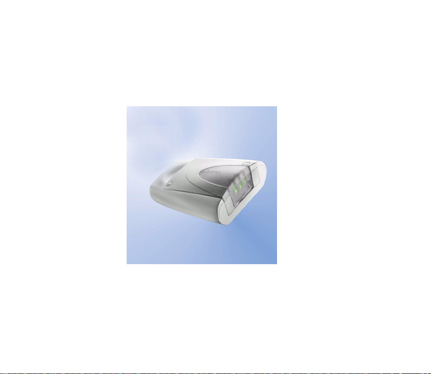
1 Introduction
The Nokia 31 is a GSM Connectivity Terminal which offers high
speed wireless connections over GSM 850/1900 MHz
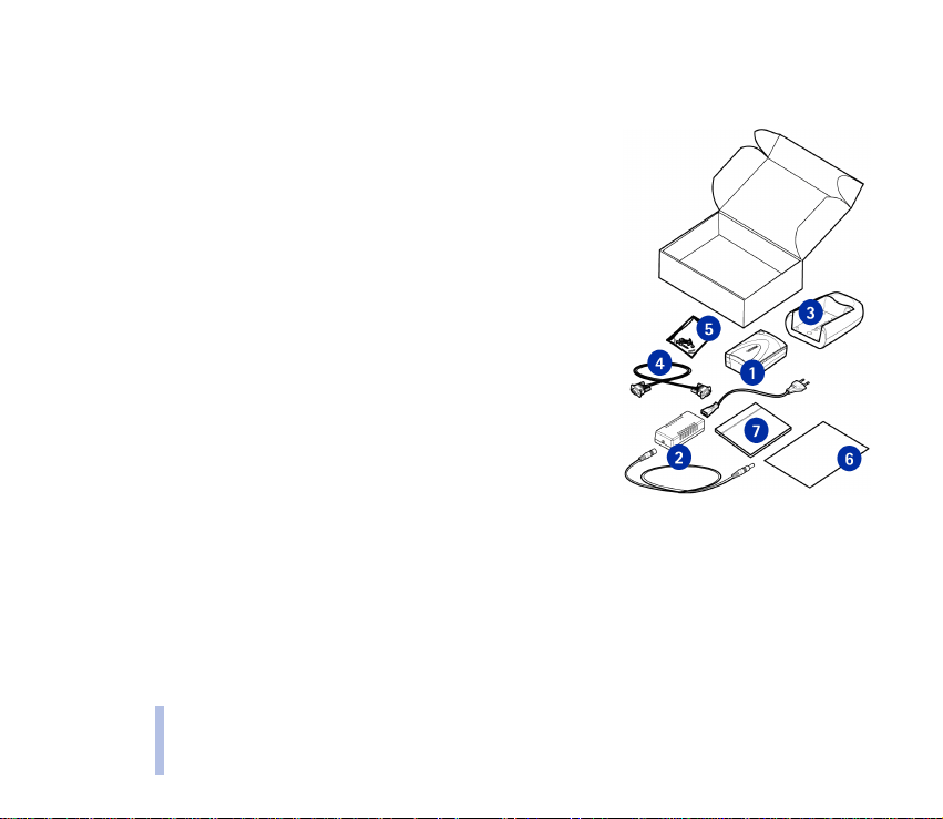
networks. The contents of the "Complete" Terminal package
include:
1 Nokia 31 GSM Connectivity Terminal
2 Power supply ACW-5A
3 Data adapter RS-232
4 Data cable RS-232
5 Installation kit
6 Product note
7 Nokia 31 CD-ROM
8 Installation pad (not shown)
OPERATION MODES
M2M
M2M stands for "machine-to-machine, man-to-machine or machine-to-man" communication.
M2M is a simple way to use wireless data transmission as a link between sys tems, remote devices
or locations and individuals.
2002 Nokia Corporation. All rights reserved.6
Page 7

The Nokia 31 terminal can be combined with the Nokia M2M Gateway to provide wireless
connections (Text Messaging, USSD, GPRS, CSD) for machine-to-machine communications. This
combination forms part of an application solution which can remotely monitor or control a pool
of devices or to connect them with existing systems.
With the Nokia 31 terminal connected to a machine through a control application, you can
remotely control a pool of devices and receive status information. The Nokia 31 terminal can be
easily integrated into various applications such as vending, security and meter control.
As an M2M communications device, the Nokia 31 terminal can be used in three operation modes:
AT command mode
M2M system mode
User control mode
AT command mode
In the AT command mode, the Nokia 31 terminal operates as a wireless modem. The wireless
connection is established and data is sent using AT commands. The AT commands which are used
to control the Nokia 31 terminal can be found in the AT Command Guide found on the Nokia 31
CD-ROM or www. americas.forum.nokia.com.
By physically connecting the Nokia 31 terminal to the RS-232 data adapter, the terminal can be
connected to a compatible PC and used as a stand-alone GSM wireless modem. The modem uses
normal communication applications such as e-mail, fax and Internet browsers.
2002 Nokia Corporation. All rights reserved.
U.S. English
7
Page 8

M2M system mode
In the M2M system mode, the Nokia 31 terminal is combined with the Nokia M2M Gateway to
form a complete, wireless end-to-end solution for machine communication.
Some of the enhanced M2M features incorporated into the Nokia 31 terminal include:
enhanced reliability and security
automatic reset if the connection between the Nokia 31 terminal and the application module
is found to be broken
mutual authentication between the Nokia 31 terminal and the Nokia M2M Gateway
data can be exchanged using CORBA method calls integrated in the application module
User control mode
User control mode enables simple applications to be controlled by mobile handsets with text
messages (Short Message Service). The control or monitoring is through general-purpose inputs
and outputs of the M2M System connector of the Nokia 31 terminal. T ext message templates that
are sent from the mobile to the Nokia 31 terminal instruct the terminal, which in turn controls a
device or system, attached to it through the M2M System connector.
DATA CONNECTIONS AND MESSAGING
The Nokia 31 terminal supports four GSM wireless network data protocols.
2002 Nokia Corporation. All rights reserved.8
Page 9

GPRS
With General Packet Radio Service (GPRS), data is transferred over the network in small, efficient,
standardized packets. The Nokia 31 terminal supports GPRS multi-slot class 6 protocol which
provides multiple timeslots for data transfer. Th e use of G PRS s ervices requires that y our netw ork
service provider supports GPRS (General Packet Radio Service) technology and you must have
subscribed to this service. The pricing of GPRS services may differ from that of normal GSM data
services. Please contact your network service provider for more information.
CSD
Circuit Switched Data (CSD) offers wireless data transfer at rates of up to 14.4 kilobits/sec.
Text Messaging
Text messaging (also called "Short Message Service") is used to send and receive messages
containing a maximum of 160 characters. Text messaging is a convenient way to pass data quickly
and easily among Nokia 31 terminals.
USSD
Unstructured Supplementary Services Data (USSD) offers reliable , interactive messa ging service s.
USSD can be used to send and receive messages containing a maximum of 182 characters. With
USSD, the session is established for the duration of the connection. This increases data transfer
reliability and shortens response times.The use of USSD services requires that your network service
provider supports USSD technology and you must have subscribed to this service.
2002 Nokia Corporation. All rights reserved.
U.S. English
9
Page 10

Note: USSD messages can only be sent to the network, not directly to another mobile
terminal.
SUPPLEME NTARY SERVICES
The Nokia 31 terminal also supports additional network dependent services such as:
Call forwarding – forwards your calls to another number which you specify.
Call restriction – restricts outgoing and incoming calls.
Call transfer – connects two different callers with each other then disconnects one’s own call
without disturbing the other two callers.
Call waiting – alerts you to an incoming call during a phone call.
In-call handling – switches between incoming and active calls.
Multiparty call – connects several callers in a single conversation.
Security option – allows restrictions such as call barring.
SECURITY
By default, the Nokia 31 terminal uses a stand ard PIN reques t. For ad ditional s ecurity, there is an
"AutoPIN" feature which can be configured to relay the PIN code to the terminal’s memory and
make the SIM card useless to any unauthorized user. The AutoPIN feature is activated by
connecting the Nokia 31 terminal to a PC and running the Nokia 31 Configurator software located
on the Nokia 31 CD-ROM or downloadable from www.americas.forum.nokia.com
terminal also includes security-related features such as GSM security codes and GSM encryption.
2002 Nokia Corporation. All rights reserved.10
. The Nokia 31
Page 11

2Set up
Install the SIM card
The terminal uses small-size, 3V SIM cards. If
another type of SIM card is installed the terminal
will not be able to recognize the card.
To install a SIM card in the Nokia 31 terminal:
1 Remove the SIM card cover by lifting the
wide end of the cover out and upwards.
2 Insert your SIM card into the slot. Make sure
that the golden contact area is facing up and
the bevelled corner is on the left (see
illustration).
3 Replace the terminal cover by pushing the
narrow end back into the terminal, then
snapping the cover closed.
Warning: Do not install, move or remove the SIM card if the terminal’s power supply
is connected to an AC wall outlet. Insert the SIM card and attach the terminal to the
data adapter before connecting the power supply.
2002 Nokia Corporation. All rights reserved.
U.S. English
11
Page 12

ATTACH THE DATA ADAPTER
There is a special M2M system connector located at the
bottom of the Nokia 31 terminal. When mounting the
terminal for modem use, this connector attaches to a
matching connector on the data adapter.
If you plan to mount the terminal on a wall , attach the data
adapter to the wall and then mount the terminal onto it.
For more details on installing the Nokia 31 terminal, see
www.americas.forum.nokia.com
.
Please note that the SIM card cannot be removed from the
Nokia 31 terminal if it is connected to the data adapter.
2002 Nokia Corporation. All rights reserved.12
Nokia 31
RS-232
Data Adapter
Page 13

CONNECT THE DATA CABLE
1 Attach the Nokia 31 terminal data cable to the data adapter.
2 Connect the other end of the data cable to the serial port of a PC
or other compatible device.
Note:You should only use the data cable (RS-232) supplied
by Nokia.
C
ONNECT THE POWER
The power connector for the Nokia 31 terminal is located at the back
end of the terminal, next to the data cable connector. When the Nokia
31 terminal is mounted into the data adapter, the power interface is
found under the edge of the data adapter.
1 Connect the power cord from the power supply to the terminal.
2 Connect the power supply to an AC wall outlet.
MOUNT THE TERMINAL
The Nokia 31 terminal can be mounted either horizontally or vertically on a suitable flat surface.
2002 Nokia Corporation. All rights reserved.
U.S. English
13
Page 14

To find the best installation location, you can use the Intensity of Field strength (IoF) function
through the terminal’s light indicators (LEDs) to find the strongest signal (see “Signal Strength”
on page 17). For more detailed information on placing the terminal, refer to the information at
www.americas.forum.nokia.com
Note: All radio transmitting devices send signals which may cause interference in
different electronic devices ( PC, television etc.). To avoid interference, place the
terminal as far as possible from other electronic devices.
.
ANTENNA S
The Nokia 31 terminal is equipped with an
efficient internal dual-band antenna;
however, depending on the installation
location and surrounding materials, the
signal strength reaching the Nokia 31
terminal may not be sufficient.
The Nokia 31 terminal has an external
antenna connector which allows you to
connect an external antenna adapter (XRM-
1). The adapter allows you to connect an external GSM antenna (with standard FME connector)
and improve signal reception. Once the external antenna is connected, the internal antenna of the
Nokia 31 terminal is not in use.
In order to properly fit the antenna cable adapter to the Nokia 31 terminal , yo u nee d to cut out a
small piece of the terminal cover which normally covers the external antenna connector.
2002 Nokia Corporation. All rights reserved.14
Page 15

Caution: In order to comply with FCC RF exposure requirements, install the Nokia 31
terminal or external antenna so that a minimum distance of 8 inches (20cm) can be
maintained between the antenna in use and all persons, with external antenna (if used)
gain not exceeding 3 dBi.
2002 Nokia Corporation. All rights reserved.
U.S. English
15
Page 16

3 User interface
The Nokia 31 terminal has three light emitting diode (LED) indicators which form the terminal’s
user interface. The LEDs appear in various combinations of red and green indicating the state of
the terminal in three different conditions:
Start-up
Normal operation
Special operation
All three LEDs can also be configured, using the Nokia 31
Configurator software application, to remain unlit during operation.
START-UP
LED 1 LED 2 LED 3 Description
- - - Power off / silent mode
Green (scan) Green (scan) Green (scan) Power on, connecting to network
- Red (blink) - PIN query / new PIN query; see Enter the
- Red (blink) Red (blink) PUK query
2002 Nokia Corporation. All rights reserved.16
PIN code, p. 20
Page 17

SIGNAL STRENGTH
The Intensity of Field (signal) strength indicators are visible during the start-up for approximately
10 seconds before the terminal shifts to Normal operation mode.
LED 1 LED 2 LED 3 Signal Strength
Red (blink) - - < -105 dBm
Green (blink) - - -105 ...-100 dBm
Green - - -100...-95 dBm
Green Green (blink) - -95... -90 dBm
Green Green - -90... -85 dBm
Green Green Green (blink) -85... -80 dBm
Green Green Green > -80 dBm Good
Note: These signal strength recommendations are especially critical for data
transmission.
Non-acceptable
Weak
Moderate
2002 Nokia Corporation. All rights reserved.
U.S. English
17
Page 18

NORMAL OPERATION
LED 1* LED 2* LED 3 Description
– – Green In service
– – Green (blink) Call on
– – Green (blink) Incoming call
– – Green/Red (blink) Message received / Voice mail in box
– – Red (blink) Message arriving and memory is full
* Controlled by using the application module in M2M System mode.
Note: If the terminal’s LEDs indicate that you have received messages, you can use a
communication application such as HyperTerminal and type in the command
AT+CMGR to read the received messages. For more detailed information, see the List
of AT commands on the Nokia 31 CD-ROM or www.americas.forum.nokia.com
SPECIAL OPERATION
LED 1 LED 2 LED 3 Description
Green/Red
(blink)
Red (blink) Red (blink) Red (blink) Failure, contact service.
Yellow Yellow Yellow Initializing.
2002 Nokia Corporation. All rights reserved.18
Green/Red
(blink)
Green/Red
(blink)
Insert SIM card.
.
Page 19

4 Modem operation
After you have properly connected the Nokia 31 terminal to the data adapter, data cable and a PC,
you must enter an access code and install the proper software drivers for your operating system.
ACCESS CODES
You can use the access codes de scribed in this section to avo id unauthorized use of the SIM ca rd
in your Nokia 31 terminal. These access codes can be changed using the Nokia 31 Configurator
software or using specific AT commands via an appropriate software application such as
HyperTerminal.
PIN code
The Personal Identification Number (PIN) code protects your SIM card against unauthorized use.
The PIN code is usually supplied with the SIM card. When the PIN code request is enabled, the
code is requested each time the Nokia 31 terminal is switched on.
If the AutoPIN feature is enabled, the PIN code will only be requested the first time you co nfigure
the Nokia 31 terminal.
PIN2 code
The PIN2 code, supplied with some SIM cards, is required to access certain functions, such as
charging unit counters. These functions are only available if supported by your SIM card.
2002 Nokia Corporation. All rights reserved.
U.S. English
19
Page 20

PUK code
The Personal Unblocking Key (PUK) code is required to change a blocked PIN code. The PUK code
may be supplied with the SIM card. If not, contact your local service provider for the code. If you
lose the code, contact your service provider.
PUK2 code
The PUK2 code, supplied with some SIM cards, is required to change a blocked PIN2 code. If you
lose the code, contact your service provider.
Security code
The security code can be used to avoid unauthorized use of your Nokia 31 terminal. The factory
setting for the security code is 12345. You can change the security code using the Nokia 31
Configurator software. Keep the new code secret and in a safe place.
Call Barring password
The barring password is needed when using the Call Barring function. You must contact your
service provider to get this password.
ENTER THE PIN CODE
The PIN code, issued by the SIM ca rd provider, p rotec ts the SIM c ard agai nst unaut horize d us e. If
the SIM card requires a PIN code, you must enter this code before you can use the Nokia 31
terminal.
2002 Nokia Corporation. All rights reserved.20
 Loading...