


 Loading...
www.mgeups.com
Network
Management Cards
User Manual
Minislot 66244
Transverse 66074
Environment Sensor 66846
T H E U N I N T E R R U P T I B L E P O W E R P R O V I D E R
Network Management Card – User Manual 34003676EN/GA Page 1/69

www.mgeups.com
Network
Management Cards
User Manual
Table of Contents
1MGE NETWORK SOLUTION____________________________________________________________4
1.1INTRODUCTION_____________________________________________________________________4
1.1.1Connecting the UPS to the Network ________________________________________________4 The Network Management Card or Proxy: __________________________________________________4
1.1.2Protecting the computers / servers _________________________________________________5
1.1.3Monitoring the UPSs over the network ______________________________________________5
1.1.4Connection ___________________________________________________________________6
1.2PRESENTATION OF THE NETWORK MANAGEMENT CARDS (NMC) ________________________________6
1.3PRESENTATION OF THE ENVIRONMENT SENSOR SOLUTION _____________________________________6
1.4DIRECT SENDING OF E-MAIL ___________________________________________________________7
1.5SENDING TEXT MESSAGES (SMS) _______________________________________________________7
1.6COMPATIBILITY WITH THE NETWORK MANAGEMENT SYSTEMS (NMS) – TRAP SENDING________________7
1.7COMPATIBILITY WITH THE LEGACY SOLUTION-PAC WAN OFFERING ______________________________7
1.8TECHNICAL DATA ___________________________________________________________________8
1.8.1Configuration _________________________________________________________________8
1.8.2Administration_________________________________________________________________8
1.8.3Network _____________________________________________________________________8
1.8.4MIB (Management Information Base)_______________________________________________8
1.8.5Environment sensor ____________________________________________________________8
2INSTALLATION AND CONFIGURATION _________________________________________________10
2.1INSTALLATION ____________________________________________________________________10
2.1.1Installing the card in the UPS ____________________________________________________10
2.1.2Connecting the card to the IT network _____________________________________________10
2.1.3Understanding front panel signals ________________________________________________10
2.2BASIC CONFIGURATION _____________________________________________________________10
2.2.1List of default parameters _______________________________________________________10
2.2.2Adjusting the network parameters ________________________________________________10
2.2.3Rebooting the card ____________________________________________________________10
2.2.4Restoring factory configuration ___________________________________________________10
2.2.5Lost password – restoring the default password _____________________________________10
2.2.6Checking that the card is working_________________________________________________10
2.3ENVIRONMENT SENSOR _____________________________________________________________10
3SUPERVISION / ADMINISTRATION VIA A WEB BROWSER _________________________________11
3.1.1Optimising the performance of your browser ________________________________________11
3.2UPS ___________________________________________________________________________12
3.2.1“UPS properties” page _________________________________________________________12
3.2.2On-line help _________________________________________________________________14
3.2.33-Phase display ______________________________________________________________15
3.2.4UPS Control _________________________________________________________________16
3.2.5UPS weekly schedule programming_______________________________________________18
3.2.6Shutdown parameters__________________________________________________________19
3.2.7Viewing the alarms ____________________________________________________________21
3.3LOGS __________________________________________________________________________22
3.3.1Measurements _______________________________________________________________22
3.3.2Event log____________________________________________________________________24
3.3.3System log __________________________________________________________________25
3.4NOTIFICATION ____________________________________________________________________26
3.4.1Email Notification _____________________________________________________________26
3.4.2Email Message Settings ________________________________________________________28
T H E U N I N T E R R U P T I B L E P O W E R P R O V I D E R
Network Management Card – User Manual 34003676EN/GA Page 2/69

www.mgeups.com
Network
Management Cards
User Manual
3.5CONFIGURATION __________________________________________________________________30
3.5.1Network Settings _____________________________________________________________31
3.5.2System _____________________________________________________________________33
3.5.3Notified Applications ___________________________________________________________35
3.5.4Central Shutdown Configuration__________________________________________________36
3.5.5Access control _______________________________________________________________37
3.5.6Time _______________________________________________________________________40
3.6ENVIRONMENT ____________________________________________________________________41
3.6.1Characteristics _______________________________________________________________41
3.6.2Environment status____________________________________________________________42
3.6.3Environment Settings __________________________________________________________43
3.6.4Log ________________________________________________________________________44
4SERVERS PROTECTION _____________________________________________________________45
4.1SET-UP OF THE SHUTDOWN PARAMETERS ________________________________________________45
4.1.1Shutdown criteria managed by the Management Card ________________________________45
4.1.2Specific set-up for long autonomy installation (> 30 mn) _______________________________46
4.1.3Controlled outlets _____________________________________________________________46
4.1.4Connecting a server protected by UM-Client to a programmable outlet ____________________46
4.2THE DIFFERENT SERVER AND UPS SHUTDOWN SEQUENCES ___________________________________48
4.2.1Extended power outage, shutdown initiated by the Shutdown Timer ______________________48
4.2.2Extended power outage, shutdown initiated by the “Low battery power” message ___________50
4.2.3Extended power outage, shutdown initiated by the Shutdown Timer, but utility restoration before the end of the Shutdown Duration________________________________________________________52
4.2.4Off/On command _____________________________________________________________54
5CONFIGURING A SET OF CARDS WITH MUPGRADE ______________________________________56
6CONFIGURATION IN LOCAL MODE AND VIA TELNET OR SSH______________________________56
6.1CONFIGURATION IN LOCAL MODE ______________________________________________________56
6.1.1Choice 1: SNMP agent configuration menu _________________________________________57
6.1.2Choice 2: UPS parameters ______________________________________________________58
6.1.3Choice 3: Access control _______________________________________________________58
6.1.4Choice 4: Restore default configuration ____________________________________________59
6.1.5Choice 5: Reset the card _______________________________________________________59
6.2CONFIGURATION VIA TELNET _________________________________________________________60
6.3CONFIGURATION VIA SSH ___________________________________________________________60
6.3.1PuTTY SSH Client Program _____________________________________________________60
7MAINTENANCE _____________________________________________________________________62
7.1SOFTWARE UPGRADE_______________________________________________________________62
7.1.1Card firmware upgrade using Mupgrade (Windows) __________________________________62
7.1.2Card software upgrade via TFTP (UNIX and Windows) ________________________________62
7.1.3Recovery tool software via the serial link ___________________________________________62
8APPENDICES_______________________________________________________________________63
8.1TABLES OF ALARMS AND EVENTS ______________________________________________________63
8.1.1Alarm table __________________________________________________________________63
8.1.2UPS event table ______________________________________________________________63
8.1.3System alarm table____________________________________________________________66
8.2GLOSSARY ______________________________________________________________________67
T H E U N I N T E R R U P T I B L E P O W E R P R O V I D E R
Network Management Card – User Manual 34003676EN/GA Page 3/69
www.mgeups.com
Network
Management Cards
User Manual
1 MGE Network Solution
1.1Introduction
Zprovides information on events concerning the supply of power to the computers connected to your computer network,
Zcarries out automatic shutdown of computer systems,
Zmonitors and controls all the UPSs connected to the network.
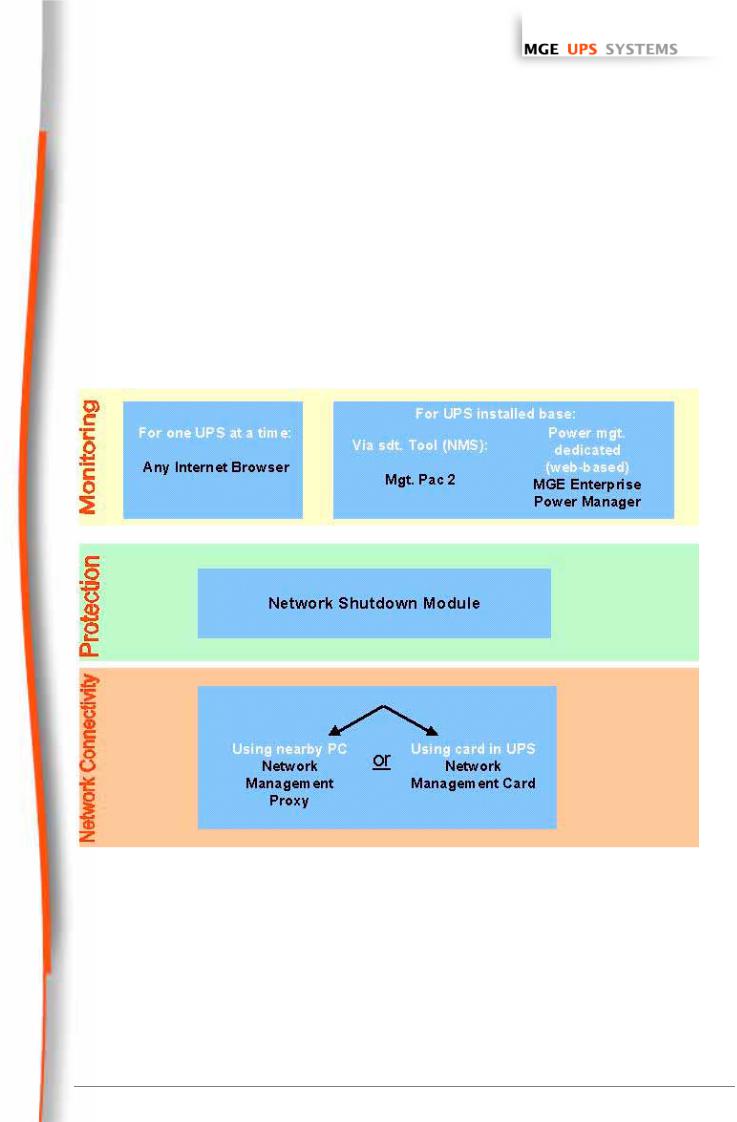
As illustrated in the picture below, MGE Network Solution provides these 3 main functions:
Zconnecting the UPS to the Network,
Zprotecting the computers,
Zmonitoring the UPSs over the Network
1.1.1 Connecting the UPS to the Network
This function can be performed either through network Cards inserted in the UPS (Network Management Card) or through a software “agent” running on a nearby PC that is called the Network Management Proxy.
The Network Management Card or Proxy:
Zmanages communication with the UPS (as well as local protection of the machine on which Proxy is installed),
Zperiodically accesses the information concerning the UPS,
T H E U N I N T E R R U P T I B L E P O W E R P R O V I D E R
Network Management Card – User Manual 34003676EN/GA Page 4/69
www.mgeups.com
Network
Management Cards
User Manual
Zmakes this information available to the connected applications (Network Shutdown Modules, Web Browser, Network Management Systems, Enterprise Power Manager)
Operation may be in standard secure mode (the default mode) or in SSL secure mode (Secure Socket Layer SSL).
1.1.2 Protecting the computers / servers
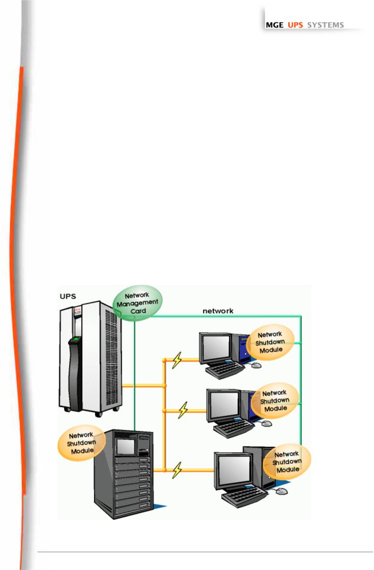
This function is performed by the Network Shutdown Module installed on each of the servers to be protected. Note that the Shutdown Module is available on several Operating Systems.
The Network Shutdown module:
Zcontinuously waits for information from the Network Management Card / Proxy connected to the MGE UPS.
Zwarns administrators and users if AC power fails and proceeds with graceful system shutdown before the
end of battery backup power is reached.
1.1.3 Monitoring the UPSs over the network
Depending on your needs, you can either use:
Zyour Internet browser to monitor each UPS, as Management Proxy and Management Card include a Web server.
Zyour company’s standard Network Management System (HP-Openview, CA Unicenter, HP Insight Manager, IBM Tivoli Netview). To simplify integration of MGE UPSs with these NMS, you can use one of the Network Management System Kits for MGE devices. These kits are available on Management Pac 2 CD-Rom. (ref 66923)
Zthe MGE supervisor " Enterprise Power Manager "
T H E U N I N T E R R U P T I B L E P O W E R P R O V I D E R
Network Management Card – User Manual 34003676EN/GA Page 5/69

www.mgeups.com
Network
Management Cards
User Manual
1.1.4 Connection
Before installing the MGE Network Solution, the UPS must be set up as indicated in the steps below.
ZShut down the computers to be protected by the UPS.
Connect the UPS to a wall outlet. (For UPSs above 3kVA, please refer to the UPS installation manual)
ZConnect the power cord of each computer to an outlet on the UPS. (For UPSs above 3kVA, please refer to the UPS installation manual)
1.1.4.1 |
How to connect UPS / agent / network : |
|
Z |
Insert the optional card in the UPS and connect the UPS to the computer network. |
|
Z |
Start the MGE UPS, then the computers. |
|
1.1.4.2 |
Setting up the protection |
|
ZSet up the Network Management Card (see user manual).
ZInstall Network Shutdown Module on all machines that are to be protected by the UPS (supplied with UPS battery backup power).
The software components for each platform and the user manuals are supplied free-of-charge on the SolutionPac 2 CD or are available for download on the www.mgeups.com Web site, in the “Download area” section”
1.2Presentation of the Network Management Cards (NMC)
MGE provides 2 different form factors for its Network Management Cards :
ZNMC Minislot for UPS systems like the Evolution, EXtreme C, Pulsar EX RT, Pulsar/Comet DX series.
ZNMC Transverse for UPS systems like the Galaxy 3000, Galaxy 5000, Galaxy PW, Pulsar and Comet EXtreme series. Other MGE UPS systems (3-phase Comet, Galaxy, EPS 6000) can be remotely managed
using the Network Management Link
.
The Network Management Cards acquire information on the operation status of the UPS systems and provide remote control of these systems by means of an ETHERNET network from any SNMP administration station or Web browser. They also supply alarms to the Network Shutdown Modules to trigger shutdown or other automatic actions for protected servers.
A simple html browser is used for supervision and configuration.
Network Management Cards are compatible with all MGE UPS SYSTEMS supervision / protection systems:
ZNetwork Shutdown Modules
ZEntreprise Power Manager
ZManagement-Pac 2
1.3Presentation of the Environment Sensor solution
The Environment Sensor solution comprises a box to be connected to the Card Settings port of the Network Management Cards:
Environment Sensor enables measurement of temperature and humidity around the UPS, consideration of external alarms via 2 dry contacts and notification of alarms according to pre-programmed thresholds.
T H E U N I N T E R R U P T I B L E P O W E R P R O V I D E R
Network Management Card – User Manual 34003676EN/GA Page 6/69

www.mgeups.com
Network
Management Cards
User Manual
1.4Direct sending of E-mail
When a UPS event occurs, the Network Management Card can directly notify up to 4 intranet or extranet addressees by e-mail (see Email Notification and Email Message Settings).
1.5Sending text messages (SMS)
SMS messages can be sent by specific configuration of the e-mail function via the internet access providers making the e-mail / SMS transfer.
1.6Compatibility with the Network Management Systems (NMS) – Trap sending
The Network Management Cards are compatible with the major Network Management Systems (IBM Tivoli, CA Unicenter, HP Insight Manager ..),. The Management-Pac 2 offering includes the necessary SNMP plug-in to allows an easy integration in the NMS. Events are notified by SNMP trap
ZNMS can subscribe on page “Notified Application”
ZSNMP sequences are described in chapter “Server protection”
The trap list can be looked over in the document “Agent's MIB description” available on mgeups.com
1.7Compatibility with the legacy Solution-Pac WAN offering
Network Management Card is compatible with the legacy protection module UM-Client and since the FA release also with the updated protection module Network Shutdown Module . It is possible to use the both modules on the same card, therefore, MGEUPS recommends to use the Network Shutdown Module on new installations.
T H E U N I N T E R R U P T I B L E P O W E R P R O V I D E R
Network Management Card – User Manual 34003676EN/GA Page 7/69

www.mgeups.com
Network
Management Cards
User Manual
1.8Technical data
1.8.1 Configuration
The user can configure the card with one of the following means:
ZWeb browser
ZLocal serial link
ZTelnet console
ZBOOTP/DHCP
ZMupgrade
1.8.2 Administration
ZUp to 50 workstations protected
ZUp to 15 browsers connected at the same time
ZE-mail sending configurable according to UPS alarms and transmission of a periodical report
ZMeasurement of temperature and humidity, adjustable thresholds, possibility of sending e-mails and shutting down the installation
ZControl of UPS on/off switching via the HTML interface
ZAdjustment and control of PowerShare outlets via the HTML interface, sequential starting of the installation and optimisation of backup time by shutting down non-priority systems
ZAdjustment of date and time via NTP server - Daylight Saving Time management
ZProtection by encrypted password.
ZProtection by secured connection SSL and SSH
ZSaving of logs in the non-volatile memory
ZAutomatic language detection according to browser configuration.
ZLanguages available: English / French / Spanish / German / Italian
ZOn-line help available for each page
ZCard firmware updated via the network
ZCard configuration deployment on your installed base through network utility (Mupgrade)
1.8.3 |
Network |
|
Z |
Fast ETHERNET 10/100 Mbits compatibility with auto-negotiation on the RJ45 outlet |
|
Z |
SNMP trap port modifiable (by default = 162) |
|
1.8.4 |
MIB (Management Information Base) |
|
ZMIB IETF UPS (RFC1628) / MIB MGE V1.7
1.8.5 Environment sensor
ZTemperature measurement from 0 to 70 °C with +/- 1°C accuracy
ZMeasurement of humidity from 0 to 100 % with +/- 6 % accuracy
ZMin / max time-stamped function for temperature and humidity
ZChoice of temperature readings in Celsius or Fahrenheit
ZHigh and low thresholds, hysteresis and offset adjustable via Web interface
ZPossibility of notification of status changes by e-mail, SMS or SNMP traps
ZPosition detection of 2 dry contacts (maximum sensor/contact distance: 20 m)
ZName and status of each configurable contact
T H E U N I N T E R R U P T I B L E P O W E R P R O V I D E R
Network Management Card – User Manual 34003676EN/GA Page 8/69

www.mgeups.com
Network
Management Cards
User Manual
ZRecording of events and measurements in the card log
ZPossibility of shutting down the installation in the event of a threshold being exceeded or on opening / closure of a dry contact
ZConnection to the card with straight CAT5 RJ45 network cables (maximum card/sensor distance: 20 m)
T H E U N I N T E R R U P T I B L E P O W E R P R O V I D E R
Network Management Card – User Manual 34003676EN/GA Page 9/69

www.mgeups.com
Network
Management Cards
User Manual
2 Installation and Configuration
For the following sections, read the installation manual supplied with the card or available for download on the www.mgeups.com web site in the “Download area – embedded Software” section
2.1Installation
2.1.1Installing the card in the UPS
2.1.2Connecting the card to the IT network
2.1.3Understanding front panel signals
2.2Basic configuration
2.2.1List of default parameters
2.2.2Adjusting the network parameters
2.2.3Rebooting the card
2.2.4Restoring factory configuration
2.2.5Lost password – restoring the default password
2.2.6Checking that the card is working
2.3Environment Sensor
Read the installation manual supplied with the box.
T H E U N I N T E R R U P T I B L E P O W E R P R O V I D E R
Network Management Card – User Manual 34003676EN/GA Page 10/69
www.mgeups.com
Network
Management Cards
User Manual
3 Supervision / Administration via a Web browser
A JVM (Java Virtual Machine) is required to ensure correct display of information in HTML pages.
ZOn a computer equipped with a Web browser (Internet Explorer or Netscape recommended), enter the address initialised previously in the Installation chapter (e.g.: http://213.30.17.30.)
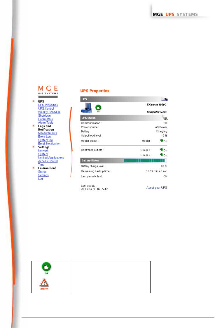
ZThe “UPS properties” home page is displayed.
3.1.1 Optimising the performance of your browser
ZTo view status changes on the UPS in real time, the browser must be configured so that it automatically refreshes all the objects on the current page.
Example on IE 6: Tools / Internet Options / General / Parameters menu, tick Every time this page is visited and validate.
T H E U N I N T E R R U P T I B L E P O W E R P R O V I D E R
Network Management Card – User Manual 34003676EN/GA Page 11/69
www.mgeups.com
Network
Management Cards
User Manual
3.2UPS
3.2.1 “UPS properties” page
ZThis page gives instant access to the essential information about your UPS. This page is automatically refreshed every 10 seconds (by default).
To change this value, go to the “System” page.
3.2.1.1 UPS zone: general information on the UPS.
Indication of the picture and generic name of the UPS range
Computer room: Customised name of your system corresponding to the “upsIdentName” object of the UPS MIB (RFC 1628)
You can change this name on the “System” page.
3.2.1.2 “UPS status” zone: essential information
Z The various icons showing the status of the UPS are:
• Normal operation
•
•Alarm present. This icon links directly to
•the alarm page
T H E U N I N T E R R U P T I B L E P O W E R P R O V I D E R
Network Management Card – User Manual 34003676EN/GA Page 12/69
www.mgeups.com
Network
Management Cards
User Manual
• |
|
|
• |
Battery operation |
|
|
|
|
|
|
|
|
• Loss of communication with the UPS |
|
|
|
|
||
• |
|
|
||
|
|
|
|
|
• |
|
|
• |
Battery fault |
|
|
|
|
|
• |
|
(green outlet) |
• |
Outlet powered – Flashing when an |
|
|
|
|
on/off sequence is in progress |
• |
|
(red outlet) |
• |
Outlet not powered or not protected |
“Communication”: indicates the status of the communication between the card and the UPS “Power source”: indicates whether the power comes from the utility or from the UPS battery “Batteries”: indicates whether the battery is being charged or discharged
“Output load level”: indicates the power percentage used at UPS output “Master output”: indicates if the UPS output is protected
“Controlled outlets”: indicates if the controlled outlets (if available) are powered.
3.2.1.3“Battery status” zone:
Z“Bargraph”: Graph showing the remaining battery charge (in percent).
Z“Battery charge level”: Remaining battery charge (in percent).
Z“Remaining backup time”: Estimation of the maximum backup time remaining before UPS shutdown. This time can be modified by the adjustments on the “Shutdown parameters” page
Z“Last periodical test”: Result of the last automatic battery test carried out by the UPS
Possible values are:
- OK: the test was completed correctly
–NOK: the battery needs to be checked
–Deactivated: the automatic battery test is not validated on the UPS
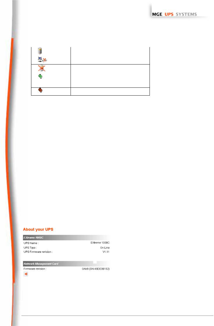
The “About your UPS” zone provides information on the UPS and the Network Shutdown Card, in particular, the model range and software version.
Note: If the UPS is connected by dry contacts, neither picture or name are indicated, the “2 contacts” title is displayed and only the following parameters are specified in the UPS status zone:
T H E U N I N T E R R U P T I B L E P O W E R P R O V I D E R
Network Management Card – User Manual 34003676EN/GA Page 13/69

www.mgeups.com
Network
Management Cards
User Manual
3.2.2 On-line help
On-line contextual help in English is available at the top of each page by clicking on the Help link, which is always located on the top right corner.
The Help page always opens a new window.
T H E U N I N T E R R U P T I B L E P O W E R P R O V I D E R
Network Management Card – User Manual 34003676EN/GA Page 14/69
www.mgeups.com
Network
Management Cards
User Manual
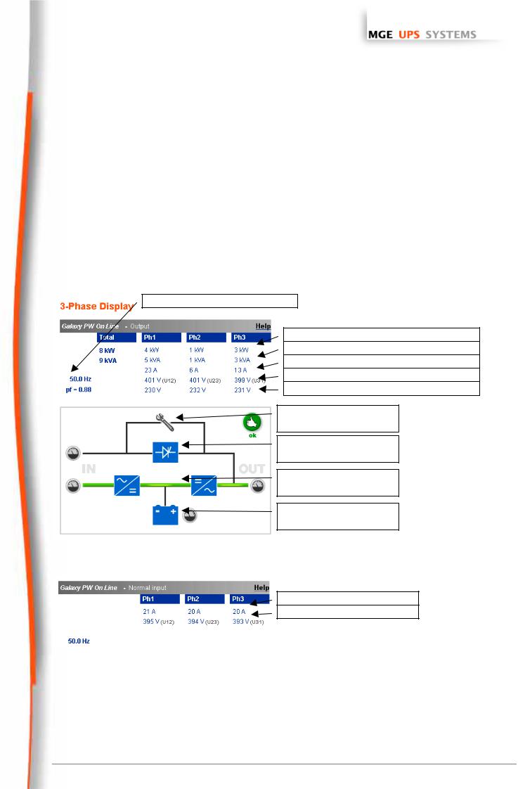
3.2.3 3-Phase display
Click 3-phase display to access to the detailed monitoring page
This item is added to the menu for all single UPSs having a three-phase output.
 The link on the gauge symbols gives access to the measurement page related to the function.
 Function symbols are outlined in red when an alarm is present.

 The red triangle, linked to the alarm page, appears when an alarm is present, otherwise a green symbol is displayed.
This page is automatically refreshed every 10 seconds (by default).
To change this value, go to the “System” page.
Frequency and power factor
Static ByPass
Rectifi |
Inverte |
Battery
3.2.3.1 Normal input measurements
Active power – Global and per phase Apparente power – Global and per phase Output current
Output voltagePhase / Phase Output voltage Phase / neutral
Maintenance position
Static switch operation
Normal operation
Battery
.
Input current
Input voltagePhase / Phase
T H E U N I N T E R R U P T I B L E P O W E R P R O V I D E R
Network Management Card – User Manual 34003676EN/GA Page 15/69
www.mgeups.com
Network Management Cards
User Manual
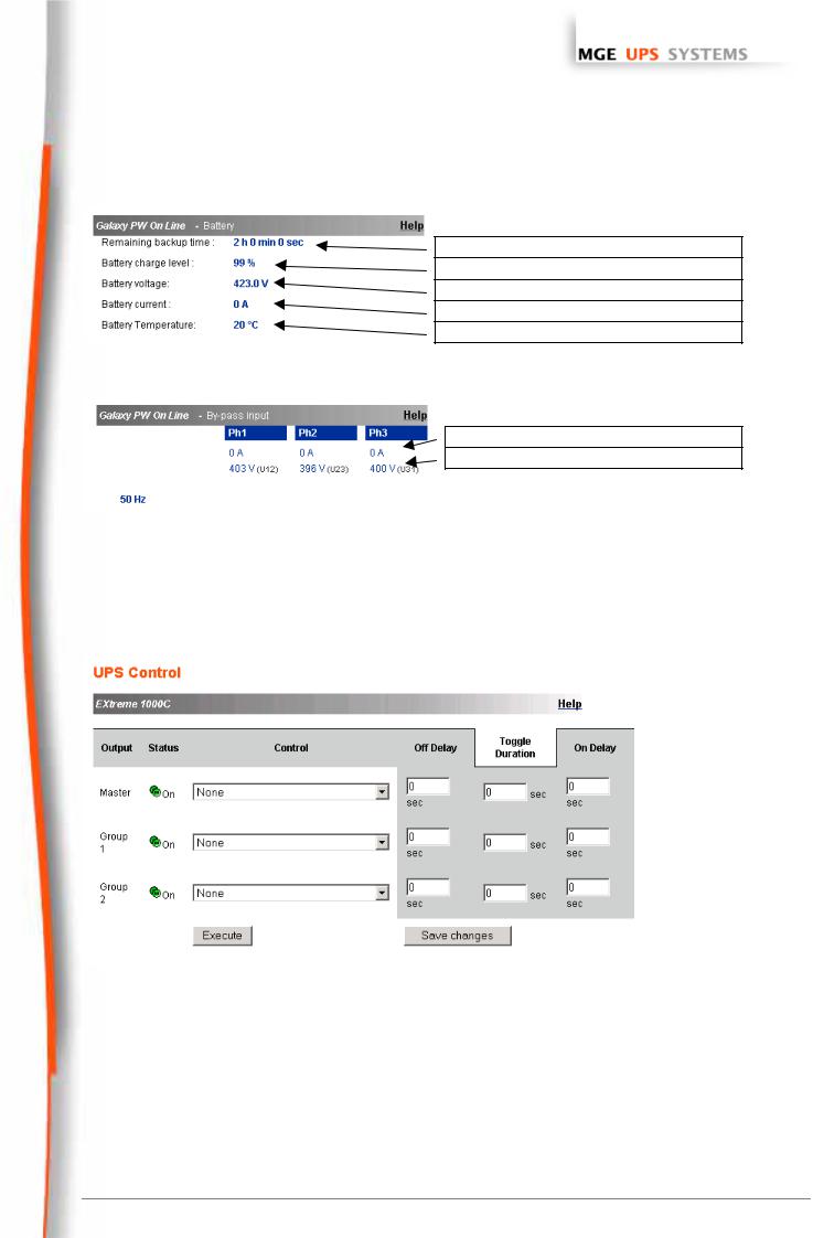
3.2.3.2 Battery measurements
Remaining backup time estimted by the UPS
Battery charge level
Battery voltage
Battery current – Negative when discharging
Battery temp. – Internal temperature probe
3.2.3.3 By Pass measurements
By Pass current
By Pass voltagePhase / Phase
3.2.4 UPS Control
Click on the “UPS Control” section in the menu.
If the UPS is not compatible with this function, a warning message is sent to the user.
UPS configuration may also prevent the commands from being properly run. Read the UPS manual for more information.
This page enables triggering of startup and shutdown sequences for the UPS main output and Controlled outlets.
ZThe status of each output is displayed by a symbol associated with the Off label (red symbol) or Powered (green symbol).
ZThe shutdown sequences take into account the time required for the registered servers to shut down without losing data (see shutdown parameters ). Once the sequence has started, the commands are disabled until it ends.
ZAfter a startup sequence, the commands are disabled for 120 seconds to enable the servers to fully restart
T H E U N I N T E R R U P T I B L E P O W E R P R O V I D E R
Network Management Card – User Manual 34003676EN/GA Page 16/69

www.mgeups.com
Network
Management Cards
User Manual
ZThe main outlet has priority over the auxiliary outlets. Shutdown of the main outlet causes the auxiliary outlets to shut down. Auxiliary outlets can only be started if the main outlet is powered
The Check column proposes six different commands, and a command is only actually started after clicking on
'Execute':
“Safe power down”: a sequence to switch off output power is launched immediately. The symbol representing the output flashes, indicating that the sequence is in progress. The systems supplied are shut down correctly while the shutdown sequence is running, then the output is cut.
“Safe power down & reboot”: A sequence to switch off then restore output power is launched immediately. The symbol representing the output flashes, indicating that the shutdown sequence is in progress. The powered systems are shut down correctly during the shutdown sequence, then the output is switched off. Finally, the restart sequence is launched at the end of the time delay specified in the “Toggle duration” parameter. The output status is updated.
“Immediate On”: a sequence to switch on output power is launched immediately. The output is re-powered and the systems supplied start up again correctly.
“Delayed, safe power down”: this is the same switch off sequence as for the “ Safe power down ” command, but postponed by the number of seconds programmed in the “Off Delay” parameter.
“Delayed, safe power down & reboot:” this is the same switch off then on sequence as for the Safe power down & reboot ” command, but postponed by the number of seconds programmed in the “ Off Delay ” parameter.
“Delayed On ”: this is the same switch on sequence as for the “ Immediate On ” command, but postponed by the number of seconds programmed in the “ On Delay ” parameter.
The Save button saves the Off Delay, Toggle duration and On Delay parameters on the card .
Security: The administrator must click on Save and enter his login / password to save modifications or run commands. The login and password by default are: MGEUPS.
T H E U N I N T E R R U P T I B L E P O W E R P R O V I D E R
Network Management Card – User Manual 34003676EN/GA Page 17/69
www.mgeups.com
Network
Management Cards
User Manual
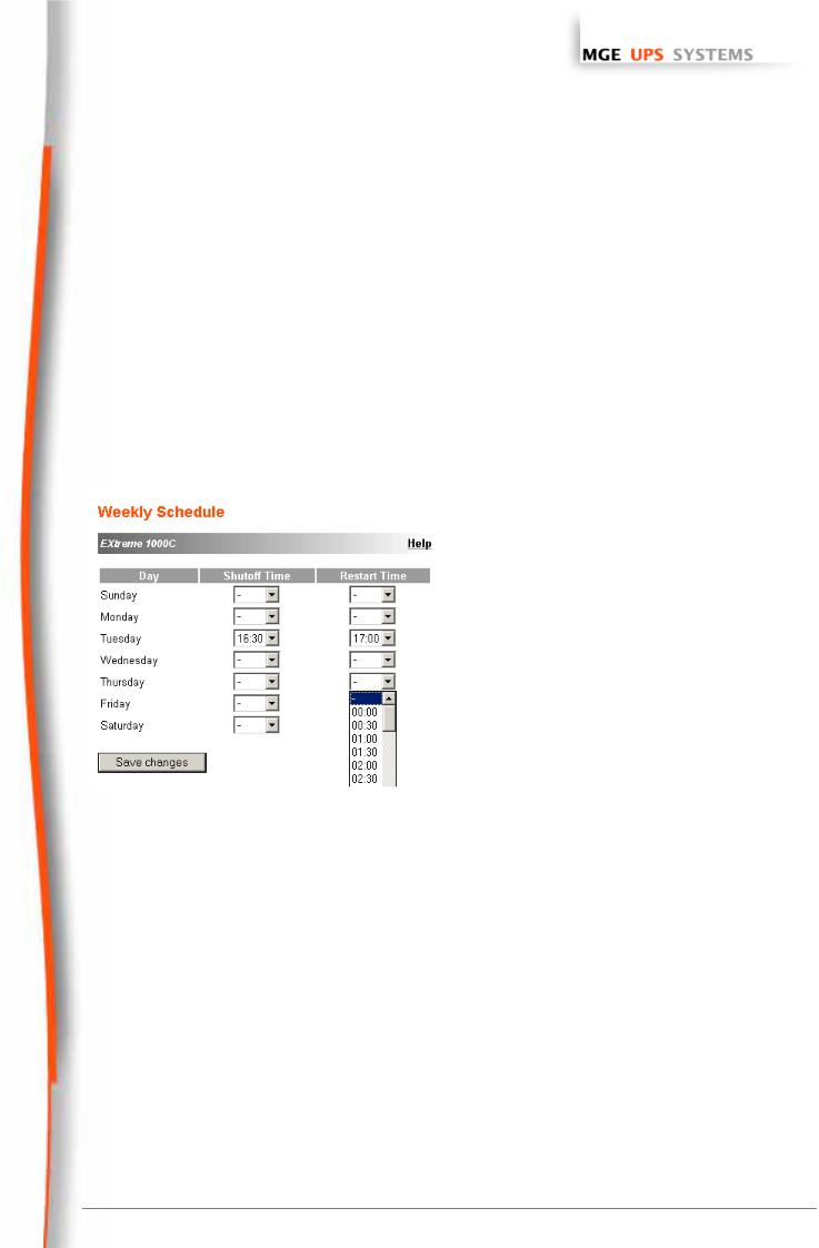
3.2.5UPS weekly schedule programming
Click on the “Weekly schedule” section of the menu.
If the UPS is not compatible with this function, a warning message is sent to the user.
UPS configuration may also prevent the commands from being properly run. Read the UPS manual for more information.
The weekly schedule enables the administrator to optimise power consumption or program a reboot of the protected equipment at a set time.
In a shutdown sequence, the Network Shutdown Modules connected to the card are informed and ensure that each machine is shut down correctly before the UPS output is switched off.
Up to 7 UPS shutdown sequences can be programmed in one week, with a minimum shutdown delay of 30 minutes.
Security: the administrator clicks on “Save” and enters his/her login / password to save any edits. The login and password by default are: MGEUPS.
T H E U N I N T E R R U P T I B L E P O W E R P R O V I D E R
Network Management Card – User Manual 34003676EN/GA Page 18/69
www.mgeups.com
Network
Management Cards
User Manual
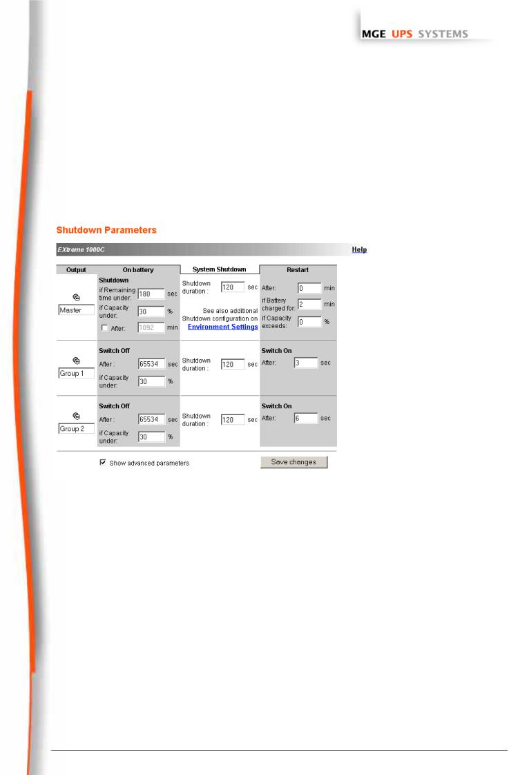
3.2.6 Shutdown parameters
Z Click on the “Shutdown parameters” section in the menu to see the list of parameters.
Important note:
For installations that do not use Network Shutdown Module (backup units, routers and other internetworking equipment, automated systems, etc.) or in the event of long backup periods, the card will send a command to the UPS to shut off end of the programmed Shutdown After time. To prevent this, the Shutdown After box must be not selected (default)
This page enables viewing and configuration of UPS operation parameters in battery mode and for power restoration.
When you tick the Show advanced parameters option, extra parameters are displayed. These parameters enable, in particular, adjustment of certain thresholds related to the percentage of remaining battery charge level.
The Output column enables each output to be named (maximum 30 characters).
Note
Priority is given to the main outlet, so the card does not accept configurations where the auxiliary outlets can be supplied while the main outlet is switched off
For the main outlet (Master)
ZShutdown after is the operating time in minutes left for users after a switch to backup before starting the shutdown sequences of the UPS and its equipment (from 0 to 1092).
ZIf remaining time under (from 0 to 9999 seconds) and If Capacity under (from 0 to 100%) are two extra conditions for remaining backup time and battery level that can trigger shutdown sequences before the “Shutdown after” period runs out
ZShutdown duration is the time required for complete shutdown of systems when a switch to backup time is long enough to trigger the shutdown sequences. It is calculated automatically at the maximum of Shutdown duration of subscribed clients but can be modified in the Advanced mode
T H E U N I N T E R R U P T I B L E P O W E R P R O V I D E R
Network Management Card – User Manual 34003676EN/GA Page 19/69

www.mgeups.com
Network
Management Cards
User Manual
ZRestart after is the minimum shutdown time before restarting the UPS after a shutdown sequence. It is thus possible to limit repeated restarts that may be due to several successive utility failures.
ZIf the Battery is charged for and If Capacity exceeds are two extra conditions for minimum battery level and maximum recharge time to be reached before restarting the UPS after utility restoration
For controlled outlets (group 1 or group 2 ), the page enables programming of operation time and level in backup mode to manage outlet load shedding in the event of electric power failure:
ZSwitch Off after (from 0 to 65534).defines the time during which the outlet is supplied starting from the moment of utility failure. Caution, this time includes the outlet shutdown duration.
ZSwitch Off if capacity under is an extra condition for outlet shutdown that can trigger the shutdown sequence before shutdown duration runs out.
ZShutdown duration is the time required for complete shutdown of the systems supplied by the outlet when an outlet shutdown sequence is launched.
It is calculated automatically using the maximum shutdown durations of subscribed clients.
ZSwitch On (from 0 to 65534). is the period between main output startup and startup of the relevant programmable outlet, therefore outlet startup can be delayed in relation to the main output.
Security: The administrator has to click on Save and enter his login/password to save any modifications. The default login and password are: MGEUPS
T H E U N I N T E R R U P T I B L E P O W E R P R O V I D E R
Network Management Card – User Manual 34003676EN/GA Page 20/69
www.mgeups.com
Network
Management Cards
User Manual
3.2.7 Viewing the alarms
ZClick on the “Alarm table” section in the menu to view the list of current alarms. The table of managed alarms is included in the appendix.
Note: The alarm number is not related to the SNMP trap number
T H E U N I N T E R R U P T I B L E P O W E R P R O V I D E R
Network Management Card – User Manual 34003676EN/GA Page 21/69
Loading...