


w w w . m g e u p s . c o m
 ⁄ ı
⁄ ı
CO
M
M
G
ET
E
U P S S Y S T E M S
Comet 40-150kVA
Uninterruptible Power Supply
Installation and User Manual

Installation and User Manual
Comet
40 - 150kVA
Installation and User Manual
Revision History
Comet 40-150kVA UPS Installation and User Manual |
86-160310-00 |
||
Revision: |
A00 |
Initial Release |
03/1997 |
|
B00 |
ECN#: 289-91 |
01/1998 |
|
C00 |
ECN#: 290-30 |
07/1998 |
|
D00 |
ECN#: 002456 |
02/2002 |
|
E00 |
ECN#: 004466 |
08/2005 |
Copyright © 2005 MGE UPS SYSTEMS, INC.
All rights reserved. Printed in U.S.A.
MGE UPS SYSTEMS, INC.
1660 Scenic Avenue Costa Mesa, CA 92626 (714) 557-1636
Customer Care Center: 1-800-438-7373 (Hours: 24/7)
86-160310-00 E00 |
i |

Comet 40-150kVA
IMPORTANT SAFETY INSTRUCTIONS
SAVE THESE INSTRUCTIONS – This manual contains important instructions for the
Comet 40-150kVA that must be followed during operation and maintenance of the equipment.
WARNING ATTENTION WARNUNG!
WARNING ATTENTION WARNUNG!
NOTE
WARNING
ATTENTION
WARNUNG!
Opening enclosures expose hazardous voltages. Always refer service to qualified personnel only.
L'ouverture des cabinets expose des tensions dangereuses. Assurez-vous toujours que le service ne soit fait que par des personnes qualifiees.
Das öffnen der Gehäuse legen gefährliche Spannungen bloss.
Service sollte immer nur von qualifizierten Personal durchgeführt werden.
As standards, specifications, and designs are subject to change, please ask for confirmation of the information given in this publication.
Comme les normes, spécifications et produits peuvent changer, veuillez demander confirmation des informations contenues dans cette publication.
Normen, Spezifizierungen und Pläne unterliegen Anderungen. Bitte verlangen Sie eine Bestätigung über alle Informationen, die in dieser Ausgabe gemacht wurden.
This equipment has been tested and found to comply with the limits for a Class A digital device, pursuant to part 15 of the FCC rules. These limits are designed to provide reasonable protection against harmful interference when the equipment is operated in a commercial environment.
This equipment generates, uses, and can radiate radio frequency energy and, if not installed and used in accordance with the instruction manual, may cause harmful interference to radio communications. Operation of this equipment in a residential area is likely to cause harmful interference in which case the user will be required to correct the interference at user's own expense.
To reduce the risk of fire or electric shock, install in a controlled indoor environment free of conductive contaminants.
This equipment is intended only for installations in a RESTRICTED ACCESS LOCATION.
Pour réduire le riske d'inccendie ou d'électrocution, installer dans une enciente intérieure contrôlée en température et humidité et sans contaminants conducteurs.
Ce matériel est destiné seulement pour des installations dans un EMPLACEMENT RESTREINT D'ACCES.
Um die Gefahr von Feuer und elektrischem Schock zu reduzieren, muss das Gerät in einem temperatur - und feuchtigkeitskontrollierten Raum, frei von leitungsfähigen Verunreinigungen, installiert werden. Dieses Gerät ist nur für die Installation an einem Ort mit qeingeschränkter Zugangserlaubnis vorgesehen.
Diese Ausrüstung ist nur für Anlagen in einem EINGESCHRäNKTEN ZUGRIFF STANDORT bestimmti.
ii |
Important Safety Instructions |
86-160310-00 E00 |

Installation and User Manual
WARNING
ATTENTION
WARNUNG!
HIGH LEAKAGE CURRENT. Earth connection essential before connecting supply.
COURANT DE FUITE ELEVE. Raccordement a la terre indispensable avant le raccordement au reseau.
Hoher Ableitstrom Vor Inbetriebnahme Schutzleiterverbindung herstellen.
Certification Standards - Three Phase UPS
IEC 1004/ANSI C62.41 Standards for Surge Withstand Ability.
FCC Part 15, Subpart J, Class A.
UL/cUL 1778, Standard for Uninterruptible Power Supply Equipment.
NEMA PE 1 - Uninterruptible Power Systems.
NFPA 70 - National Electrical Code.
ISO 9001.
Safety of Persons
The UPS has its own internal power source (the battery). Consequently, the power outlets may be energized even if the UPS is disconnected from the AC power source.
The UPS must be properly grounded.
The battery supplied with the UPS contains small amounts of toxic materials. To avoid accidents, the directives listed below must be observed:
-Never burn the battery (risk of explosion).
-Do not attempt to open the battery (the electrolyte is dangerous for the eyes and skin).
-Comply with all applicable regulations for the disposal of the battery.
-Batteries constitute a danger (electrical shock, burns). The short-circuit current may be very high. Precautions must be taken for all handling: remove watches, rings, bracelets and any other metal objects, use tools with insulated handles.
-Do not lay tools or metal parts on top of batteries.
Product Safety
A protection circuit breaker must be installed upstream and be easily accessible.
The UPS can be disconnected from the AC power source by opening the input circuit breaker.
UPS must be connected to a nearby power source that is easily accessible.
Never block the ventilation grates of the UPS.
The UPS must be installed in a controlled environment.
Special Precautions
The UPS connection instructions and operation described in the manual must be followed in the indicated order.
Check that the indications on the rating plate correspond to your AC powered system and to the actual electrical consumption of all the equipment to be connected to the UPS.
Before and after the installation, if the UPS remains de-energized for a long period, the UPS must be energized for a period of 24 hours, at least once every 3 months (for a normal storage temperature less than 25°C). This charges the battery, thus avoiding possible irreversible damage.
86-160310-00 E00 |
Certification Standards and Safety of Persons |
iii |

Comet 40-150kVA
(This page left blank intentionally)
iv |
86-160310-00 E00 |

Contents
|
section |
description . . . . . . . . . . . . . . . . . . . . . . . . . . . . . . . . . . . . . . . . . |
. .page |
|
|
Revision History . . . . . . . . . . . . . . . . . . . . . . . . . . . . . . . . . . . . . |
. . . . . .i |
|
|
IMPORTANT SAFETY INSTRUCTIONS . . . . . . . . . . . . . . . . . . |
. . . . .ii |
|
|
Certification Standards - Three Phase UPS . . . . . . . . . . . . . . . |
. . . . .iii |
|
|
Safety of Persons . . . . . . . . . . . . . . . . . . . . . . . . . . . . . . . . . . . . |
. . . . .iii |
|
|
Product Safety . . . . . . . . . . . . . . . . . . . . . . . . . . . . . . . . . . . . . . |
. . . . .iii |
|
|
Special Precautions . . . . . . . . . . . . . . . . . . . . . . . . . . . . . . . . . . |
. . . . .iii |
|
|
CAUTION: Record All Serial Numbers! . . . . . . . . . . . . . . . . . . . |
. . .c iv |
|
|
Symbol Usage . . . . . . . . . . . . . . . . . . . . . . . . . . . . . . . . . . . . . . |
. . .c vi |
|
|
Section Descriptions . . . . . . . . . . . . . . . . . . . . . . . . . . . . . . . . . |
. . .c vi |
Section 1 |
System Description and Specifications |
|
|
|
1.0 |
Scope . . . . . . . . . . . . . . . . . . . . . . . . . . . . . . . . . . . . . . . . . . . . . |
.1 — 1 |
|
1.1 |
General Description . . . . . . . . . . . . . . . . . . . . . . . . . . . . . . . . . . |
.1 — 1 |
|
1.2 |
Major Components . . . . . . . . . . . . . . . . . . . . . . . . . . . . . . . . . . . |
.1 — 3 |
|
1.3 |
Specifications . . . . . . . . . . . . . . . . . . . . . . . . . . . . . . . . . . . . . . . |
.1 — 8 |
|
1.3.1 |
AC Input Ratings . . . . . . . . . . . . . . . . . . . . . . . . . . . . . . . . . . . . |
.1 — 9 |
|
1.3.2 |
AC Output Ratings . . . . . . . . . . . . . . . . . . . . . . . . . . . . . . . . . . . |
.1 — 9 |
|
1.3.3 |
DC Ratings . . . . . . . . . . . . . . . . . . . . . . . . . . . . . . . . . . . . . . . . . |
.1 — 9 |
|
1.3.4 |
Mechanical Specifications (UPS Cabinet Only) . . . . . . . . . . . . . |
1 — 10 |
|
1.3.5 |
Environmental Specifications . . . . . . . . . . . . . . . . . . . . . . . . . . . |
1 — 10 |
|
1.3.6 |
DB15 Connector Pinouts and Designations . . . . . . . . . . . . . . . . |
1 — 10 |
|
1.4 |
Options and Accessories . . . . . . . . . . . . . . . . . . . . . . . . . . . . . . |
1 — 11 |
|
1.4.1 |
UPS Options . . . . . . . . . . . . . . . . . . . . . . . . . . . . . . . . . . . . . . . . |
1 — 11 |
|
1.4.2 |
Software and Communication Package . . . . . . . . . . . . . . . . . . . |
1 — 11 |
Section 2 |
Installation |
|
|
|
2.0 |
Scope . . . . . . . . . . . . . . . . . . . . . . . . . . . . . . . . . . . . . . . . . . . . . |
.2 — 1 |
|
2.1 |
Receiving . . . . . . . . . . . . . . . . . . . . . . . . . . . . . . . . . . . . . . . . . . |
.2 — 1 |
|
2.2 |
Handling . . . . . . . . . . . . . . . . . . . . . . . . . . . . . . . . . . . . . . . . . . . |
.2 — 1 |
|
2.3 |
Storage . . . . . . . . . . . . . . . . . . . . . . . . . . . . . . . . . . . . . . . . . . . . |
.2 — 2 |
|
2.4 |
Prerequisite to Installation . . . . . . . . . . . . . . . . . . . . . . . . . . . . . |
.2 — 2 |
|
2.4.1 |
Environmental . . . . . . . . . . . . . . . . . . . . . . . . . . . . . . . . . . . . . . |
.2 — 2 |
|
2.4.2 |
Mechanical . . . . . . . . . . . . . . . . . . . . . . . . . . . . . . . . . . . . . . . . . |
.2 — 3 |
|
2.4.3 |
Electrical . . . . . . . . . . . . . . . . . . . . . . . . . . . . . . . . . . . . . . . . . . . |
.2 — 3 |
|
2.5 |
Installation Procedures . . . . . . . . . . . . . . . . . . . . . . . . . . . . . . . . |
.2 — 4 |
|
2.5.1 |
Placement . . . . . . . . . . . . . . . . . . . . . . . . . . . . . . . . . . . . . . . . . . |
.2 — 4 |
86-160310-00 E00 |
Contents |
c i |

Comet 40-150kVA
|
section |
description . . . . . . . . . . . . . . . . . . . . . . . . . . . . . . . . . . . . . . . . . |
. .page |
Section 2 |
Installation (continued) |
|
|
|
2.6 |
Connections . . . . . . . . . . . . . . . . . . . . . . . . . . . . . . . . . . . . . . . . |
.2 — 4 |
|
2.6.1 |
Main AC Input . . . . . . . . . . . . . . . . . . . . . . . . . . . . . . . . . . . . . . |
.2 — 4 |
|
2.6.2 |
Bypass AC Input (Optional) . . . . . . . . . . . . . . . . . . . . . . . . . . . . |
.2 — 4 |
|
2.6.3 |
Remote Emergency Power Off (REPO) . . . . . . . . . . . . . . . . . . |
.2 — 4 |
|
2.6.4 |
AC Output . . . . . . . . . . . . . . . . . . . . . . . . . . . . . . . . . . . . . . . . . . |
.2 — 5 |
|
2.6.5 |
Battery . . . . . . . . . . . . . . . . . . . . . . . . . . . . . . . . . . . . . . . . . . . . |
.2 — 5 |
Section 3 |
Operation |
|
|
|
3.0 |
Scope . . . . . . . . . . . . . . . . . . . . . . . . . . . . . . . . . . . . . . . . . . . . . |
.3 — 1 |
|
3.1 |
Power Flow . . . . . . . . . . . . . . . . . . . . . . . . . . . . . . . . . . . . . . . . |
.3 — 1 |
|
3.1.1 |
Power Flow, For Normal Operation . . . . . . . . . . . . . . . . . . . . . . |
.3 — 1 |
|
3.1.2 |
Power Flow, For On Battery Operation . . . . . . . . . . . . . . . . . . . |
.3 — 1 |
|
3.1.3 |
Power Flow, For Bypass Operation . . . . . . . . . . . . . . . . . . . . . . |
.3 — 2 |
|
3.2 |
Graphical User Interface, Controls and Indicators . . . . . . . . . . . |
.3 — 2 |
|
3.3 |
Startup Procedures . . . . . . . . . . . . . . . . . . . . . . . . . . . . . . . . . . . |
.3 — 5 |
|
3.3.1 |
Preliminary Checks . . . . . . . . . . . . . . . . . . . . . . . . . . . . . . . . . . . |
.3 — 5 |
|
3.3.2 |
Powering Up the Comet . . . . . . . . . . . . . . . . . . . . . . . . . . . . . . . |
.3 — 5 |
|
3.4 |
Inverter Manual Startup . . . . . . . . . . . . . . . . . . . . . . . . . . . . . . . |
.3 — 5 |
|
3.5 |
Operating Procedures . . . . . . . . . . . . . . . . . . . . . . . . . . . . . . . . |
.3 — 6 |
|
3.5.1 |
Normal Operation . . . . . . . . . . . . . . . . . . . . . . . . . . . . . . . . . . . . |
.3 — 6 |
|
3.5.2 |
Operation on Battery Power . . . . . . . . . . . . . . . . . . . . . . . . . . . . |
.3 — 6 |
|
3.5.3 |
Battery Duration . . . . . . . . . . . . . . . . . . . . . . . . . . . . . . . . . . . . . |
.3 — 6 |
|
|
3.5.3.1 Return to AC Power . . . . . . . . . . . . . . . . . . . . . . . . . . . |
.3 — 6 |
|
3.5.4 |
Overload . . . . . . . . . . . . . . . . . . . . . . . . . . . . . . . . . . . . . . . . . . . |
.3 — 7 |
|
3.6 |
Emergency Shutdown Using EPO/REPO . . . . . . . . . . . . . . . . . |
.3 — 8 |
|
3.7 |
Forced Transfer . . . . . . . . . . . . . . . . . . . . . . . . . . . . . . . . . . . . . |
.3 — 8 |
|
3.8 |
Maintenance Bypass . . . . . . . . . . . . . . . . . . . . . . . . . . . . . . . . . |
.3 — 8 |
|
3.8.1 |
From Normal Maintenance Bypass Mode . . . . . . . . . . . . . . . . . |
.3 — 8 |
|
3.8.2 |
From Maintenance Bypass to Normal Mode . . . . . . . . . . . . . . . |
.3 — 9 |
|
3.9 |
Shutdown Procedures . . . . . . . . . . . . . . . . . . . . . . . . . . . . . . . . |
3 — 10 |
|
3.9.1 |
Inverter Shutdown . . . . . . . . . . . . . . . . . . . . . . . . . . . . . . . . . . . |
3 — 10 |
|
3.9.2 |
Powering Down . . . . . . . . . . . . . . . . . . . . . . . . . . . . . . . . . . . . . |
3 — 10 |
|
3.10 |
Alarms . . . . . . . . . . . . . . . . . . . . . . . . . . . . . . . . . . . . . . . . . . . . . |
3 — 10 |
Section 4 |
Maintenance |
|
|
|
4.0 |
Scope . . . . . . . . . . . . . . . . . . . . . . . . . . . . . . . . . . . . . . . . . . . . . |
.4 — 1 |
|
4.1 |
Battery Safety . . . . . . . . . . . . . . . . . . . . . . . . . . . . . . . . . . . . . . . |
.4 — 1 |
|
4.2 |
Preventive Maintenance . . . . . . . . . . . . . . . . . . . . . . . . . . . . . . . |
.4 — 1 |
|
4.3 |
Replacement Parts . . . . . . . . . . . . . . . . . . . . . . . . . . . . . . . . . . . |
.4 — 2 |
c ii |
Contents |
86-160310-00 E00 |

Installation and User Manual
Figures
figure description . . . . . . . . . . . . . . . . . . . . . . . . . . . . . . . . . . . . . . . . . . . . . . . . .page
1-1: Comet 40-80kVA. . . . . . . . . . . . . . . . . . . . . . . . . . . . . . . . . . . . . . . . . . . . . . . . .
1-2: Comet 100-150kVA . . . . . . . . . . . . . . . . . . . . . . . . . . . . . . . . . . . . . . . . .1 — 1 1-3: Single Line Diagram for the Comet 40-80kVA . . . . . . . . . . . . . . . . . . . . .1 — 2 1-4: Single Line Diagram for the Comet 100-150kVA . . . . . . . . . . . . . . . . . . .1 — 2
1-5: Front View of the Comet 40-80kVA . . . . . . . . . . . . . . . . . . . . . . . . . . . . .1 — 4 1-6: Rear View of the Comet 40-80kVA . . . . . . . . . . . . . . . . . . . . . . . . . . . . .1 — 5 1-7: Front View of the Comet 100-150kVA . . . . . . . . . . . . . . . . . . . . . . . . . . .1 — 6 1-8: Front View of Communications Components for
the Comet 100-150kVA . . . . . . . . . . . . . . . . . . . . . . . . . . . . . . . . . . . . . .1 — 7 1-9: Pinouts on the DB15 Connector . . . . . . . . . . . . . . . . . . . . . . . . . . . . . . .1 — 10
2-1: The Comet 100-150kVA on Pallet . . . . . . . . . . . . . . . . . . . . . . . . . . . . . .2 — 2
3-1: Power Flow, For Normal Operation . . . . . . . . . . . . . . . . . . . . . . . . . . . . .3 — 1 3-2: Power Flow, For On Battery Operation . . . . . . . . . . . . . . . . . . . . . . . . . .3 — 1 3-3: Power Flow, For Bypass Operation . . . . . . . . . . . . . . . . . . . . . . . . . . . . .3 — 2 3-4: Comet Front Panel GUI, Controls and Indicators . . . . . . . . . . . . . . . . . .3 — 3 3-5: Output Current Overload Curve . . . . . . . . . . . . . . . . . . . . . . . . . . . . . . . .3 — 7 3-6: Output Power Overload Curve . . . . . . . . . . . . . . . . . . . . . . . . . . . . . . . . .3 — 7
Tables
table description . . . . . . . . . . . . . . . . . . . . . . . . . . . . . . . . . . . . . . . . . . . . . . . . .page
1-1: Comet 40-150kVA Specifications . . . . . . . . . . . . . . . . . . . . . . . . . . . . . . .1 — 8 1-2: UPS Manager Dry Contact Interface . . . . . . . . . . . . . . . . . . . . . . . . . . .1 — 10
2-1: Recommended upstream protective device sizing * . . . . . . . . . . . . . . . . |
2 — 3 |
MGE Warranty & Proprietary Rights for Three Phase Products
MGE Standard Three Phase Warranty
Proprietary Rights Statement
Warranty and Product Registration
User Information
Product Information
Warranty Extension (Warranty+)
Customer Care Center - Three Phase Products
Technical Support and Product Services
Who to Contact
Scheduling Field Service Engineer Support
Return Policy for Repair of Three Phase Products (RGA)
Glossary
Reorder Form
86-160310-00 E00 |
Contents |
c iii |

Comet 40-150kVA
CAUTION: Record All Serial Numbers!
RECORD ALL SERIAL NUMBERS FOR THE COMET UPS AND ACCESSORIES. THESE SERIAL NUMBERS WILL BE REQUIRED IF YOUR SYSTEM NEEDS SERVICE. KEEP THIS MANUAL IN A PLACE WHERE YOU CAN REFERENCE THE SERIAL NUMBERS IF SERVICE IS REQUIRED!
UPS SERIAL NUMBER: _______________________________________________________
BATTERY SERIAL NUMBER: ___________________________________________________
ADDITIONAL MODULES SERIAL NUMBERS:
____________________________ ______________________________
____________________________ ______________________________
____________________________ ______________________________
____________________________ ______________________________
____________________________ ______________________________
____________________________ ______________________________
NOTES:
c iv |
CAUTION: Record All Serial Numbers! |
86-160310-00 E00 |
Installation and User Manual
(This page left blank intentionally)
86-160310-00 E00 |
c v |
Comet 40-150kVA
Symbol Usage
This manual uses five icon symbols with text to convey important information and tips.
WARNING |
Information provided to protect the user and service personnel against safety |
|
|
|
hazards and/or possible equipment damage. |
|
|
|
|
|
|
|
|
|
|
CAUTION |
Information provided to protect the user and service personnel against possible |
|
|
|
equipment damage. |
|
|
|
|
|
|
|
|
|
|
ELECTRICAL |
Information provided to protect the user and service personnel against possible |
|
|
|
electrical hazard and equipment damage. |
|
|
|
|
|
|
|
|
|
|
IMPORTANT |
Information provided as an operating instruction, or as an operating tip. |
|
|
NOTE |
|
|
|
|
|
|
|
Information provided as an operating tip or an equipment feature. |
|
||
|
|
|
|
Section Descriptions
1System Description and Specifications
Provides a general description of the Comet 40-150kVA Uninterruptible Power Systems major components, available options, and system specifications.
2Installation
Installation of the Comet 40-150kVA UPS, which include receiving, handling, and storage procedures; prerequisites to installation; installation procedures; and startup procedures.
3Operation
Important information on the Comet 40-150kVA systems’ operation procedure sequences; for normal, on battery, and bypass operation, with descriptions of the control and display indicators.
NOTE |
For details on the Graphical User Interface (GUI) display, please refer to |
|
manual 86-160316-00. |
|
|
4Maintenance
Preventive maintenance and battery safety instructions for Comet 40-150kVA UPS, and information about replacement parts, and customer service.
A Glossary provides definitions of abbreviations and terms used in this manual.
NOTE |
This manual provides technical information required for operation and |
|
maintenance of the Comet 40-150kVA Uninterruptible Power System (UPS). |
|
Please read this manual before operating the Comet 40-150kVA equipment. |
|
Please retain this manual for future reference. |
|
|
c vi |
Symbol Usage and Section Descriptions |
86-160310-00 E00 |
System Description and Specifications
1.0Scope
Provides a general description of the Comet 40-150kVA Uninterruptible Power Systems major components, available options, and system specifications.
1.1General Description
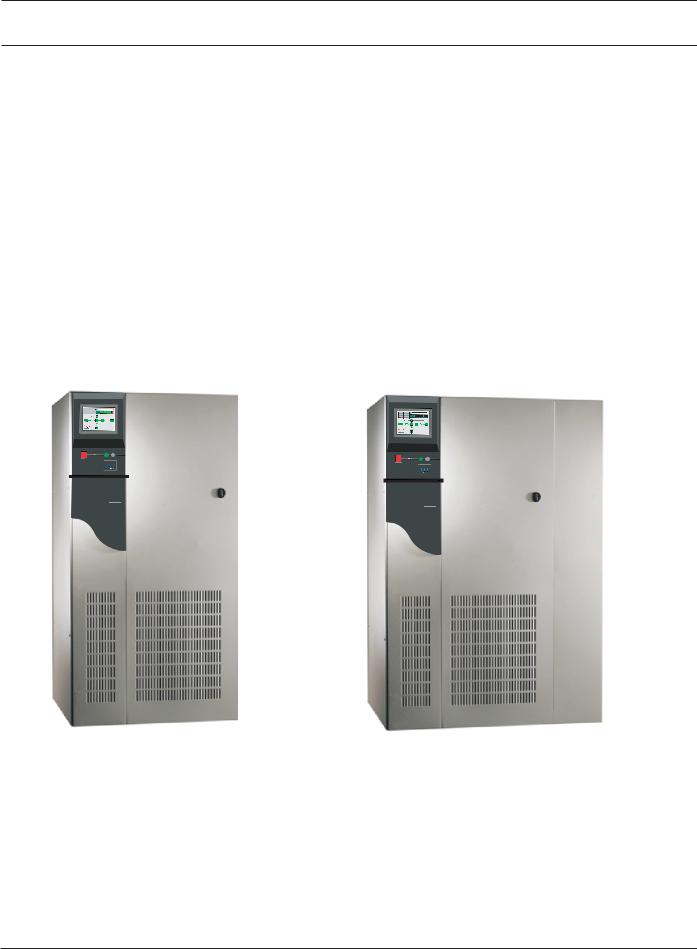
The Comet family consists of compact, high-efficiency Uninterruptible Power Systems which are available in power ratings from 40-150kVA, and are optimized for compatibility with nonlinear computer-type loads. Computer-aided UPS diagnostics and modular construction assure that any required service can be identified and completed rapidly. Remote system monitoring, remote annunciation of UPS performance signals and communication capabilities allow total control of the UPS by its user. See Figures 1-1 and 1-2.
The Comet UPS and its auxiliary equipment are designed for installation in a room where humidity and temperature can be controlled. The recommended and maximum environmental parameters are listed in the Specifications section of this document.
Figure 1-1: Comet 40-80kVA. |
Figure 1-2: Comet 100-150kVA. |
||
|
|
|
|
 ⁄ ı
⁄ ı
COMET
M G E
U P S S Y S T E M S
 ⁄ ı
⁄ ı
COMET
M G E
U P S S Y S T E M S
86-160310-00 E00 |
System Description and Specifications |
1 — 1 |
Comet 40-150kVA
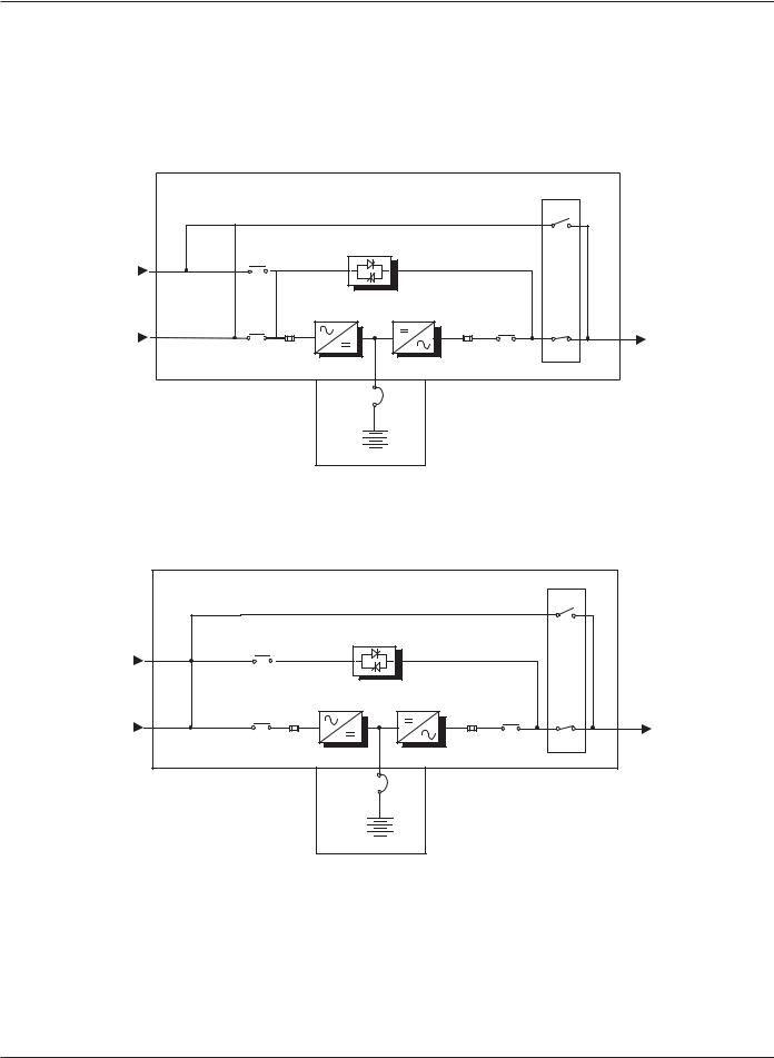
Figure 1-3, and 1-4 show single-line diagrams of a typical UPS system installation. During normal operation, utility power (Main Input) is supplied to the UPS Rectifier where it is converted to DC voltage. The Inverter converts the DC voltage from the Rectifier to three-phase regulated AC voltage, which supplies the critical load. During power failure conditions, the Inverter is supplied by the stored energy in the batteries, and the load is powered continuously with no disruption.
Figure 1-3: Single Line Diagram for the Comet 40-80kVA.
UPS CABINET
|
STATIC SWITCH |
|
||
BYPASS |
KA2 |
|
|
|
|
|
|
||
AC INPUT |
|
|
SR1 |
|
(OPTIONAL) |
|
|
||
|
|
|
||
MAIN |
KA1 |
K3N |
TO |
|
|
||||
|
|
CRITICAL |
||
AC INPUT |
|
|
||
INPUT |
OUTPUT |
LOAD |
||
|
||||
|
FUSES RECTIFIER |
INVERTER FUSES |
|
|
|
BATTERY |
QF1 |
|
|
|
CABINET |
|
||
|
BATTERY |
|
||
Figure 1-4: Single Line Diagram for the Comet 100-150kVA.
|
UPS CABINET |
|
|
|
|
|
KA2 |
STATIC SWITCH |
|
|
|
BYPASS |
|
|
|
|
|
|
|
|
|
|
|
AC INPUT |
|
|
|
|
SR1 |
|
|
|
|
|
|
MAIN |
KA1 |
|
|
K3N |
TO |
|
|
|
|||
|
|
|
|
CRITICAL |
|
AC INPUT |
|
|
|
|
|
INPUT |
|
|
OUTPUT |
LOAD |
|
|
|
|
|||
|
FUSES |
RECTIFIER |
INVERTER |
FUSES |
|
|
|
BATTERY |
QF1 |
|
|
|
|
CABINET |
|
|
|
|
|
|
|
|
|
|
|
BATTERY |
|
|
|
1 — 2 |
System Description and Specifications |
86-160310-00 E00 |

Installation and User Manual
1.2Major Components
The following is a description of the cabinets and major components. Refer to Figures 1-5 to 1-8.
UPS Cabinet |
Converts the input AC power to direct current and charges the battery. DC power |
|
is converted back to clean AC power by the inverter for the critical load. Section |
|
3 describes the operation in detail. |
Auxiliary Cabinet |
Performs the voltage conversion for the input AC and/or bypass AC using step- |
|
up and/or step-down transformers. |
Battery Cabinet |
The battery cabinet stores energy for use by the Inverter. The stored energy is |
|
utilized in the event that the AC input power from the utility source fails, or falls |
|
outside of acceptable tolerances. The internal Battery Charger maintains the |
|
charge of the battery system. The DC output voltage of the charger is tempera- |
|
ture regulated to ensure an optimal charge voltage. If a customer supplied battery |
|
system is to be used, an external battery charger may be necessary. |
|
The standard battery system is housed in a separate enclosure. For systems where |
|
additional back-up time is required, up to two (2) additional battery cabinets are |
|
available. |
|
A standard battery cabinet is available in an adjacent configuration or a stand- |
|
alone configuration. Adjacent battery cabinets are attached to the right side of the |
|
UPS using c-brackets provided with the cabinet. Stand-alone battery cabinets |
|
are remote from the UPS. Refer to the battery cabinet installation drawing for |
|
more details. An external battery system can also be supplied by the customer. |
Rectifier |
Converts the AC input voltage from the utility source into a DC voltage, supplying |
|
the Inverter. |
Inverter |
Converts the DC voltage supplied from either the Rectifier or the battery system into |
|
a three-phase AC voltage. An AC output filter is used to achieve a computer-grade |
|
sinewave output voltage waveform, with a total harmonic distortion of less than 2% |
|
under linear-load conditions. |
Static Switch |
Transfers the load between the Inverter output and the bypass AC source without |
|
interrupting the supply of power to the load, allowing the load to continue |
|
operation in the event of a UPS fault. The Static Switch circuit assures that |
|
voltage from the UPS output cannot be fed back to the utility input lines. |
Battery System |
Stores energy for use by the Inverter. The stored energy is utilized in the event |
|
that the AC input power from the utility source fails, or falls outside of acceptable |
|
tolerances. The internal Battery Charger maintains the charge of the battery |
|
system. The DC output voltage of the charger is temperature regulated to ensure |
|
an optimal charge voltage. If a customer supplied battery system is to be used, |
|
an external battery charger may be necessary. |
86-160310-00 E00 |
System Description and Specifications |
1 — 3 |

Comet 40-150kVA
Figure 1-5: Front View of the Comet 40-80kVA.
1 (KA1) Input Contactor
(K3N) Output Contactor
(KA2) Bypass Input Contactor (Optional)
(F1, F2, F3) Input Fuses
(F4, F5, F6) Output Fuses
(SR1) Rotary Switch
Rectifier/Static Switch Assembly
Inverter Assembly
Feedback PCA
DC Power Supply PCA
Interconnect PCA
High-Frequency Power Supply PCA
(FU1-FU6) Power Supply Fuses
Teleservice Receptacles (J1-J2) & Fuse (FU13)
Heatsink Cooling Fans
(TB3) Separate Bypass Input Terminal Block
Battery Connections
(TB1) Main Input Terminal Block
(TB2) Output Terminal Block
(SR2) Fan Control Switch
DETAIL BEHIND ITEM 25
A
01
04
05
02
(FU7-FU12) Fan and Teleservice Fuses
Ground Busbar
Neutral Busbar
Bottom of Top-Entry Channel
1 — 4 |
System Description and Specifications |
86-160310-00 E00 |
Installation and User Manual
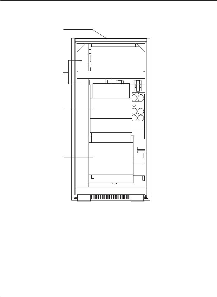
Figure 1-6: Rear View of the Comet 40-80kVA.
TOP ENTRY
CONDUIT LANDING
TOP ENTRY
CHANNEL
T1 INPUT TRANSFORMER (OPTIONAL)
T2 OUTPUT TRANSFORMER (OPTIONAL)
86-160310-00 E00 |
System Description and Specifications |
1 — 5 |
 Loading...