


w w w . m g e u p s . c o m
Galaxy 3000
10-30kVA
Uninterruptible Power Systems
Installation and User Manual

Galaxy 3000 10-30kVA
Galaxy 3000
10-30kVA
Installation and User Manual
Revision History
Galaxy 3000 10-3-kVA UPS Installation and User Manual
Revision: A00 |
Initial Release |
05/01 |
A01 |
ECN 002152 |
08/01 |
A02 |
ECN 002271 |
10/01 |
B00 |
ECN 002473 |
03/02 |
C01 |
ECN 002565 |
02/03 |
C02 |
ECN 003280 |
05/03 |
C03 |
ECN 003507 |
08/03 |
C04 |
ECN 003723 |
01/04 |
C05 |
ECN 004064 |
10/04 |
Copyright © 2004 MGE UPS SYSTEMS, INC.
All rights reserved. Printed in U.S.A.
MGE UPS SYSTEMS, INC.
1660 Scenic Avenue Costa Mesa, CA 92626 (714) 557-1636
Technical Support:
1-800-523-0142 (during business hours)
Customer Care Center: 1-800-438-7373 (Hours: 24/7)
ii |
86-172010-00 C05 |

Contents
section |
description . . . . . . . . . . . . . . . . . . . . . . . . . . . . . . . . . . . . . . . . . . . |
page |
|
Revision History . . . . . . . . . . . . . . . . . . . . . . . . . . . . . . . . . . . . . . . |
. . .ii |
|
IMPORTANT SAFETY INSTRUCTIONS . . . . . . . . . . . . . . . . . . . . |
. . .v |
|
Safety of Persons . . . . . . . . . . . . . . . . . . . . . . . . . . . . . . . . . . . . . . |
. .vii |
|
CAUTION: Record All Serial Numbers! . . . . . . . . . . . . . . . . . . . . . |
. .viii |
|
Typographical and Symbol Usage . . . . . . . . . . . . . . . . . . . . . . . . . |
. . .ix |
|
Section Descriptions . . . . . . . . . . . . . . . . . . . . . . . . . . . . . . . . . . . |
. . .ix |
Quick Start
Getting Started with Galaxy 3000 . . . . . . . . . . . . . . . . . . . . . . . . . . . . . . . . . . |
.QS—1 |
|
First steps by an on-site qualified Technical Engineer . . . . . . . . . . . . . . . . . . |
.QS—1 |
|
Final steps by MGE Field Service Engineer . . . . . . . . . . . . . . . . . . . . . . . . . . . . |
QS—1 |
|
Required Equipment and Tools . . . . . . . . . . . . . . . . . . . . . . . . . . . . . . . . . . . . . |
QS—1 |
|
STEP 1 Unpacking and Positioning . . . . . . . . . . . . . . . . . . . . . . . . . . |
QS—2 |
|
STEP 2 |
Connect the Main Utility Power . . . . . . . . . . . . . . . . . . . . . . |
QS—3 |
STEP 3 |
Connect the Output to the Distribution Panel (Load) . . . . . . |
QS—4 |
STEP 4 |
Call MGE UPS Systems for Field Engineer Service . . . . . . |
QS—4 |
STEP 5 |
Arrival of MGE Field Engineer . . . . . . . . . . . . . . . . . . . . . . . |
QS—4 |
Operator Interface Panel . . . . . . . . . . . . . . . . . . . . . . . . . . . . . . . . . . . . . . . . . . |
QS—5 |
|
Quick Start Notes . . . . . . . . . . . . . . . . . . . . . . . . . . . . . . . . . . . . . . . . . . . . . . . . |
QS—6 |
|
Section 1 |
Introduction |
|
|
|
1.0 |
Scope . . . . . . . . . . . . . . . . . . . . . . . . . . . . . . . . . . . . . . . . . . . . . |
.1 — 1 |
|
1.1 |
General Description . . . . . . . . . . . . . . . . . . . . . . . . . . . . . . . . . . |
.1 — 1 |
|
1.1.1 |
Major Components . . . . . . . . . . . . . . . . . . . . . . . . . . . . . . . . . . . . |
1 — 2 |
|
1.1.2 Galaxy 3000 Micro and Standard Cabinets . . . . . . . . . . . . . . . . . |
1 — 2 |
|
|
1.1.3 |
Preparation for Operation . . . . . . . . . . . . . . . . . . . . . . . . . . . . . . . |
1 — 2 |
|
1.1.4 Cabinet Descriptions and Placement . . . . . . . . . . . . . . . . . . . . . . |
1 — 3 |
|
|
1.1.5 Cabinet Clearance and Environmental Requirements . . . . . . . . . |
1 — 3 |
|
|
|
1.1.5.1 Air Flow / Heat Rejection . . . . . . . . . . . . . . . . . . . . . . . . |
1 — 3 |
|
|
1.1.5.2 Recommended Operating Environments . . . . . . . . . . . . |
1 — 3 |
|
1.2 |
Cabinet Footprints and Electrical Entries . . . . . . . . . . . . . . . . . . . |
1 — 5 |
|
1.2.1 Conduit Plate Locations (top entry) . . . . . . . . . . . . . . . . . . . . . . . |
1 — 5 |
|
|
1.2.2 Conduit Plate Locations (bottom entry) . . . . . . . . . . . . . . . . . . . . |
1 — 5 |
|
|
1.2.3 |
Single Line Diagram . . . . . . . . . . . . . . . . . . . . . . . . . . . . . . . . . . . |
1 — 6 |
|
1.3 |
Preparation for Storage . . . . . . . . . . . . . . . . . . . . . . . . . . . . . . . . |
1 — 6 |
86-172010-00 C05 |
Contents |
i |

Galaxy 3000 10-30kVA
Section 2 |
Setup and Installation |
|
|
|
2.0 |
Scope . . . . . . . . . . . . . . . . . . . . . . . . . . . . . . . . . . . . . . . . . . . . . |
.2 — 1 |
|
2.1 |
Electrical Specifications . . . . . . . . . . . . . . . . . . . . . . . . . . . . . . . . |
2 — 1 |
|
|
Environmental Recommendations . . . . . . . . . . . . . . . . . . . . . . . . |
2 — 1 |
|
2.2 |
Electrical Connections . . . . . . . . . . . . . . . . . . . . . . . . . . . . . . . . . |
2 — 2 |
|
|
2.2.1 Electrical Connections (UPS Module) . . . . . . . . . . . . . . . . . . . . . |
2 — 2 |
|
|
2.2.1.1 Main AC Input Connections . . . . . . . . . . . . . . . . . . . . . |
2 — 3 |
|
|
2.2.1.2 Bypass AC Input Connections (optional) . . . . . . . . . . . |
2 — 3 |
|
|
2.2.1.3 AC Output Connections . . . . . . . . . . . . . . . . . . . . . . . . |
2 — 3 |
|
2.3 |
Connecting Remote Emergency Power Off Cables . . . . . . . . . . . |
2 — 4 |
|
|
2.3.1 Connection of Relay Communication Card . . . . . . . . . . . . . . . . . |
2 — 4 |
|
2.4 |
Removing the Cover . . . . . . . . . . . . . . . . . . . . . . . . . . . . . . . . . . . |
2 — 5 |
|
|
2.4.2 Characteristics of the Output Contacts . . . . . . . . . . . . . . . . . . . . |
2 — 6 |
|
|
2.4.3 Characteristics of the Input Contacts . . . . . . . . . . . . . . . . . . . . . . |
2 — 6 |
|
2.5 |
Check Points Before and After Start Up . . . . . . . . . . . . . . . . . . . . |
2 — 6 |
Section 3 |
Operation |
|
|
|
|
3.0 |
Scope . |
. . . . . . . . . . . . . . . . . . . . . . . . . . . . . . . . . . . . . . . . . . . . |
. .3 —1 |
|
3.1 |
Preparing for Start Up . . . . . . . . . . . . . . . . . . . . . . . . . . . . . . . . . |
.3 —1 |
|
|
3.1.1 Pre-Start Up Safety Check List . . . . . . . . . . . . . . . . . . . . . . . . . . |
.3 —1 |
||
|
3.1.2 Normal Start Up Procedure . . . . . . . . . . . . . . . . . . . . . . . . . . . . . |
.3 —2 |
||
|
3.1.3 Post Start Up Safety Check List . . . . . . . . . . . . . . . . . . . . . . . . . |
.3 —3 |
||
|
3.1.4 |
Normal Shutdown Procedure . . . . . . . . . . . . . . . . . . . . . . . . . . . |
.3 —3 |
|
|
3.2 |
Operator Interface Screens . . . . . . . . . . . . . . . . . . . . . . . . . . . . . |
.3 —4 |
|
|
3.2.1 |
Screen Saver Display . . . . . . . . . . . . . . . . . . . . . . . . . . . . . . . . . |
.3 —5 |
|
|
3.2.2 |
Operational Summary Display . . . . . . . . . . . . . . . . . . . . . . . . . . . |
.3 —5 |
|
|
3.2.3 |
Main Menu Display . . . . . . . . . . . . . . . . . . . . . . . . . . . . . . . . . . . |
.3 —6 |
|
|
3.2.4 |
Battery Measurements Display . . . . . . . . . . . . . . . . . . . . . . . . . . |
.3 —6 |
|
|
3.2.5 |
Power Measurements Display . . . . . . . . . . . . . . . . . . . . . . . . . . . |
.3 —7 |
|
|
3.2.7 |
Voltage Measurements Display . . . . . . . . . . . . . . . . . . . . . . . . . . |
.3 —8 |
|
|
3.2.8 |
Frequency Measurements Display . . . . . . . . . . . . . . . . . . . . . . . |
.3 —8 |
|
|
3.2.9 |
Ratios Display . . . . . . . . . . . . . . . . . . . . . . . . . . . . . . . . . . . . . . . |
.3 —9 |
|
|
|
3.2.10 |
Mimic Diagrams . . . . . . . . . . . . . . . . . . . . . . . . . . . . . . . |
.3 —9 |
|
|
3.2.11 |
Status Displays Menu . . . . . . . . . . . . . . . . . . . . . . . . . . . |
3 —10 |
|
|
3.2.12 |
Commands Menu . . . . . . . . . . . . . . . . . . . . . . . . . . . . . . |
3 —10 |
ii |
Contents |
86-172010-00 C05 |

Installation and User Manual
Section 4 Maintenance
4.0 |
Scope . . . . . . . . . . . . . . . . . . . . . . . . . . . . . . . . . . . . . . . . . . . . . . . |
4 —1 |
4.1 |
Servicing Batteries . . . . . . . . . . . . . . . . . . . . . . . . . . . . . . . . . . . . . |
4 —1 |
MGE Warranty & Proprietary Rights for Single Phase Products
MGE Warranty
Proprietary Rights Statement
Warranty and Product Registration
User Information
Product information
Warranty Extension (Warranty+) not available on products
MGE Customer Care Center
Technical Support and Product Services
Who To Contact
Scheduling Field Service Engineer Support
Return Policy for Repair (RMA)
Glossary
Index
Reorder Form
86-172010-00 C05 |
Contents |
iii |

Galaxy 3000 10-30kVA
Figures
figure |
description . . . . . . . . . . . . . . . . . . . . . . . . . . . . . . . . . . . . . . . . . . . |
page |
QS-1: Pallet Mounting Configuration for the Galaxy 3000. . . . . . . . . . . . . . . . .QS—2 QS-2: Utility Power Connection. . . . . . . . . . . . . . . . . . . . . . . . . . . . . . . . . . . . .QS—3 QS-3: Terminal Blocks. . . . . . . . . . . . . . . . . . . . . . . . . . . . . . . . . . . . . . . . . . . .QS—4 QS-4: Operator Input Panel. . . . . . . . . . . . . . . . . . . . . . . . . . . . . . . . . . . . . . . .QS—5 QS-5: Bypass Switch Set to Bypass Mode. . . . . . . . . . . . . . . . . . . . . . . . . . . .QS—6
1-1: Galaxy 3000 UPS Systems. . . . . . . . . . . . . . . . . . . . . . . . . . . . . . . . . . . . .1 — 1 1-2: UPS Cabinet Showing the Airflow and Recommended Clearance. . . . . . .1 — 4 1-3: A Typical Configuration for Bottom Entry Knockouts and
Footprints for Galaxy 3000. . . . . . . . . . . . . . . . . . . . . . . . . . . . . . . . . . . .1 — 5 1-4: Galaxy 3000 UPS System - Single Line Diagram. . . . . . . . . . . . . . . . . . .1 — 6
2-1: Typical Power Connections. . . . . . . . . . . . . . . . . . . . . . . . . . . . . . . . . . . . . .2 — 3 2-2: Remove Cover Diagram. . . . . . . . . . . . . . . . . . . . . . . . . . . . . . . . . . . . . . . .2 — 5
3-1: |
Bypass Switch. . . . . . . . . . . . . . . . . . . . . . . . . . . . . . . . . . . . . . . . . . . . . . .3 —2 |
|
3-2: |
Operator Input Panel Indicators. . . . . . . . . . . . . . . . . . . . . . . . . . . . . . . . . .3 —4 |
|
3-3: Screen Saver Movement within the |
||
|
display indicates the unit is active. . . . . . . . . . . . . . . . . . . . . . . . . . . . . . .3 —5 |
|
3-4: |
Operational Summary Display. . . . . . . . . . . . . . . . . . . . . . . . . . . . . . . . . . .3 —5 |
|
3-5: |
Main Menu. 3 —6 |
|
3-6: |
Battery Measurements. |
. . . . . . . . . . . . . . . . . . . . . . . . . . . . . . . . . . . . . . . .3 —6 |
3-7: |
Power Measurements. . |
. . . . . . . . . . . . . . . . . . . . . . . . . . . . . . . . . . . . . . . .3 —7 |
3-8: Current Measurements. |
. . . . . . . . . . . . . . . . . . . . . . . . . . . . . . . . . . . . . . . .3 —7 |
|
3-9: Voltage Measurements. |
. . . . . . . . . . . . . . . . . . . . . . . . . . . . . . . . . . . . . . . .3 —8 |
|
3-10: |
Frequency Measurements. . . . . . . . . . . . . . . . . . . . . . . . . . . . . . . . . . . . .3 —8 |
|
3-11: |
Ratios. 3 —9 |
|
3-12: |
Mimic Diagram. . . . . . . . . . . . . . . . . . . . . . . . . . . . . . . . . . . . . . . . . . . . .3 —9 |
|
3-13: |
Status Displays Menu. |
. . . . . . . . . . . . . . . . . . . . . . . . . . . . . . . . . . . . . . .3 —10 |
3-14: |
Commands Menu. . . . . . . . . . . . . . . . . . . . . . . . . . . . . . . . . . . . . . . . . .3 —10 |
|
3-15: |
Settings Menu. . . . . . . . . . . . . . . . . . . . . . . . . . . . . . . . . . . . . . . . . . . . .3 —11 |
|
Tables
table |
description . . . . . . . . . . . . . . . . . . . . . . . . . . . . . . . . . . . . . . . . . . . |
page |
1-1: Heat Rejection Data. . . . . . . . . . . . . . . . . . . . . . . . . . . . . . . . . . . . . . . . . .1 — 3
2-1: Electrical Specifications for the Galaxy 3000. . . . . . . . . . . . . . . . . . . . . . . .2 — 1 2-2: Relay Contacts (communications card). . . . . . . . . . . . . . . . . . . . . . . . . . .2 — 4
iv |
Contents |
86-172010-00 C05 |

Installation and User Manual
IMPORTANT SAFETY INSTRUCTIONS
SAVE THESE INSTRUCTIONS – This manual contains important instructions for Galaxy
4000 that must be followed during operation and maintenance of the equipment.
 WARNING ATTENTION WARNUNG!
 WARNING ATTENTION WARNUNG!
NOTE
WARNING
ATTENTION
WARNUNG!
Opening enclosures expose hazardous voltages. Always refer service to qualified personnel only.
L'ouverture des cabinets expose des tensions dangereuses. Assurez-vous toujours que le service ne soit fait que par des personnes qualifiees.
Das öffnen der Gehäuse legen gefährliche Spannungen bloss. Service sollte immer nur von qualifizierten Personal durchgeführt werden.
As standards, specifications, and designs are subject to change, please ask for confirmation of the information given in this publication.
Comme les normes, spécifications et produits peuvent changer, veuillez demander confirmation des informations contenues dans cette publication.
Normen, Spezifizierungen und Pläne unterliegen Anderungen. Bitte verlangen Sie eine Bestätigung über alle Informationen, die in dieser Ausgabe gemacht wurden.
This equipment has been tested and found to comply with the limits for a Class A digital device, pursuant to part 15 of the FCC rules. These limits are designed to provide reasonable protection against harmful interference when the equipment is operated in a commercial environment.
This equipment generates, uses, and can radiate radio frequency energy and, if not installed and used in accordance with the instruction manual, may cause harmful interference to radio communications. Operation of this equipment in a residential area is likely to cause harmful interference in which case the user will be required to correct the interference at user's own expense.
To reduce the risk of fire or electric shock, install in a controlled indoor environment free of conductive contaminants.
This equipment is intended only for installations in a RESTRICTED ACCESS LOCATION.
Pour réduire le riske d'inccendie ou d'électrocution, installer dans une enciente intérieure contrôlée en température et humidité et sans contaminants conducteurs.
Ce matériel est destiné seulement pour des installations dans un EMPLACEMENT RESTREINT D'ACCES.
Um die Gefahr von Feuer und elektrischem Schock zu reduzieren, muss das Gerät in einem temperatur - und feuchtigkeitskontrollierten Raum, frei von leitungsfähigen Verunreinigungen, installiert werden. Dieses Gerät ist nur für die Installation an einem Ort mit qeingeschränkter Zugangserlaubnis vorgesehen.
Diese Ausrüstung ist nur für Anlagen in einem
EINGESCHRäNKTEN ZUGRIFF STANDORT bestimmti.
86-172010-00 C05 |
Important Safety Instructions |
v |

Galaxy 3000 10-30kVA
WARNING
ATTENTION
WARNUNG!
HIGH LEAKAGE CURRENT. Earth connection essential before connecting supply.
COURANT DE FUITE ELEVE. Raccordement a la terre indispensable avant le raccordement au reseau.
Hoher Ableitstrom Vor Inbetriebnahme Schutzleiterverbindung
herstellen.
Certification Standards - Three Phase UPS
IEEE 587-1980/ANSI C62.41 1980 Standards for Surge Withstand Ability
FCC rules and regulations of Part 15, Subpart J, Class A
UL listed under 1778, Standards for Uninterruptible Power Supply Equipment
NEMA PE 1 (National Electrical Manufacturers Association) - Uninterruptible Power Systems
NEMA 250 (National Electrical Manufacturers Association)
– Enclosures for Electrical Equipment (1000 Volts Maximum)
NFPA 70 – National Electrical Code
ISO 9001
Occupational Safety & Health Administration (OSHA)
vi |
Certification Standards |
86-172010-00 C05 |

Installation and User Manual
Safety of Persons
The UPS has its own internal power source (the battery). Consequently, the power terminals may be energized even if the UPS is disconnected from the AC power source.
The UPS must be properly grounded.
The battery supplied with the UPS contains small amounts of toxic materials. To avoid accidents, the directives listed below must be observed:
-Never burn the battery (risk of explosion).
-Do not attempt to open the battery (the electrolyte is dangerous for the eyes and skin).
-Comply with all applicable regulations for the disposal of the battery.
-Batteries constitute a danger (electrical shock, burns). The short-circuit current may be very high. Precautions must be taken for all handling: remove watches, rings, bracelets and any other metal objects, use tools with insulated handles.
-Do not lay tools or metal parts on top of batteries.
Product Safety
Upstream protectioin must be installed and be easily accessible.
The UPS can be disconnected from the AC power source by opening the input protective devices.
UPS must be connected to a nearby power source that is easily accessible.
Never block the ventilation openings of the UPS.
The UPS must be installed in a controlled environment.
Special Precautions
The UPS connection instructions and operation described in the manual must be followed in the indicated order.
Check that the indications on the rating nameplate correspond to your AC powered system and to the actual electrical consumption of all the equipment to be connected to the UPS.
Before and after the installation, if the UPS remains de-energized for a long period, the UPS must be energized for a period of 24 hours, at least once every 3 months (for a normal storage temperature less than 25°C). This charges the battery, thus avoiding possible irreversible damage.
86-172010-00 C05 |
Safety of Persons |
vii |

Galaxy 3000 10-30kVA
CAUTION: Record All Serial Numbers!
RECORD ALL SERIAL NUMBERS FOR THE GALAXY 3000 AND ACCESSORIES. THESE SERIAL NUMBERS WILL BE REQUIRED IF YOUR SYSTEM NEEDS SERVICE. KEEP THIS MANUAL IN A PLACE WHERE YOU CAN REFERENCE THE SERIAL NUMBERS IF SERVICE IS REQUIRED!
UPS SERIAL NUMBER: _______________________________________________________
BATTERY SERIAL NUMBER: ____________________________________________________
AUXILIARY SERIAL NUMBER: ___________________________________________________
ADDITIONAL SERIAL NUMBERS:
____________________________ ______________________________
____________________________ ______________________________
____________________________ ______________________________
____________________________ ______________________________
____________________________ ______________________________
____________________________ ______________________________
NOTES:
viii |
CAUTION: Record All Serial Numbers |
86-172010-00 C05 |
Installation and User Manual
Typographical and Symbol Usage
Typographical conventions are designed for ease of use and location of information in procedures.
“< >” angle brackets and bolded text in procedures denote a prompt for User action:
For example: 1. After the selections are complete, click on the <Save> button.
Bold text indicates important names and titles related to the subject of the procedure.
For example: 1. Enter a new document name into the Name of File text field.
This manual uses four icon symbols with text to convey important information and tips.
WARNING |
Indicates information provided to protect the user and service |
|
personnel against safety hazards and/or possible equipment damage. |
|
|
|
|
CAUTION |
Indicates information provided to protect the user and service |
|
personnel against possible equipment damage. |
|
|
IMPORTANT |
Indicates information provided as an operating instruction, or as an |
|
operating tip. |
NOTE |
|
|
|
Indicates information provided as an operating tip or an equipment |
|
|
feature. |
|
|
Section Descriptions
Quick Start
This section is a quick start guide to unpack, setup, and make necessary connections before installation of the Galaxy 3000 UPS.
1Introduction
Provides a general description of the Galaxy 4000 systems intended use, major components, and environmental and mechanical specifications.
2Setup and Installation
Guides the user through tools and equipment required for unpacking and performing connections required for initial installation. Included are the electrical specifications, environmental recommendations and connection details.
3Operation
Provides startup, shutdown, and normal operation of the Galaxy 3000 UPS. Included are pre and post startup safety checklists.
4Maintenance
Describes maintenance and safety information on servicing batteries for the Galaxy 3000.
A Glossary provides definitions of abbreviations and terms used in this manual.
86-172010-00 C05 |
Typographical and Symbol Usage |
ix |

Galaxy 3000 10-30kVA
(This page left blank intentionally)
x |
86-172010-00 C05 |
Quick Start
Getting Started with Galaxy 3000
System Setup describes receiving and handling of the Galaxy 3000, a description of major components, the battery cabinet, and definition of the control panel indicators, which includes electrical, mechanical and environmental specifications.
MGE also recommends obtaining an MGE field service engineer for final installation and basic startup for single and parallel units.
CAUTION Scheduling of the MGE Field Service Engineers typically should be done 7 to 10 days before they are required on-site. If the startup of the UPS is critical to maintaining your schedule, please call the MGE toll free telephone number at 1-800-438-7373 for assistance. The MGE Field Service Engineers will insure a quick installation
for the initial safe startup and configuration of your Galaxy 3000.
Final installation and start-up should be completed by a qualified MGE Field Service Engineer.
First steps by an on-site qualified Technical Engineer
Step 1. Unpack and position the unit.
Step 2. Connect the main (utility) power.
Step 3. Connect the output to the power distribution panel.
Final steps by MGE Field Service Engineer
Step 4. Call MGE and wait for the MGE Field Service Engineer to complete the installation.
Step 5. The MGE Field Service Engineer finalizes installation and the startup process.
Optional: |
Procedure for temporary power prior to the final startup. |
Required Equipment and Tools
The following equipment and tools are recommended for on-site installation:
Digital volt meter (DVM)
1/8 inch slotted screwdriver
Pallet jack/forklift
Conduit installation tools
Nut driver set
86-172010-00 C05 |
Quick Start |
QS—1 |

Galaxy 3000 10-30kVA
STEP 1 Unpacking and Positioning
This section describes installation of the Galaxy 3000 10-30 kVA UPS, including receiving, handling, and storage procedures; prerequisites to the installation; installation procedures; and start-up procedures.
Once the Galaxy 3000 UPS System has been inspected and received from the shipping courier, the unit should be moved with the use of a fork lift or pallet jack to a position as close to the final installation location as possible.
Figure QS-1: Pallet Mounting Configuration for the Galaxy 3000.
Installation should be performed by a qualified electrician and should conform to local and national electrical codes.
Prior to any installation, the following items should be observed upon receipt of the Galaxy 3000 10-30 kVA UPS. The casters on the unit will allow it to be positioned into the final installation location. At this point, the leveling legs can be adjusted to provide a level and stable footing for the Galaxy 3000 UPS system. See Figure QS-1.
1)Inspect shipment for any damage prior to receipt. Damage claims should be filed directly with the courier. Replacements for damaged components should be ordered through MGE Customer Support Services at 1-800- 438-7373.
2)Move equipment as close to the final location as possible using a pallet jack or forklift.
3)Once equipment is close to the installation location, and If configuration is optional pallet mount, remove the Galaxy 3000 UPS from the shipping pallet using extreme caution when rolling the cabinet off the pallet as its weight may exceed 500 lbs. See Figure QS-1.
4)All cabinets are equipped with casters allowing the equipment to be placed into final position. Push cabinets very slowly into position to avoid any tipping hazard.
5)Once in position, adjust the leveling legs to provide a fixed and stable footing for the Galaxy 3000 UPS system.
6)At this point, the UPS system can either be prepared for operation, or for storage until such time as it may be required for service.
QS—2 |
Quick Start |
86-172010-00 C05 |

Installation and User Manual
STEP 2 Connect the Main Utility Power
All Galaxy 3000 UPS systems provide the option for dual (redundant) utility power inputs. Whether the single or dual inputs are selected, the connection of the utility feed is made to the same terminal block strip in the Galaxy 3000 UPS system.
From the diagram Figure QS-2 below, it can be seen that the main power feed to the Galaxy 3000 system should be connected to the terminal blocks TB1 on the right hand side of the strip. If a bypass AC source is available (and the unit was specified to include a second AC source), this power should be connected to the middle set of terminal blocks TB3.
If the Galaxy 3000 system was specified for a second (bypass) AC source, but a separate power source is not available, then jumpers should be installed from the primary AC source to the terminal blocks for the bypass AC source.
|
NOTE |
The three phase power should be supplied as a Wye with a separate |
|
|
neutral that will be connected to the input neutral busbar. |
|
|
If the second (bypass) AC source if provided from a source other than |
|
|
|
|
|
that of the main input, it is recommended to use isolation transformers |
|
|
so that the neutral of both AC sources can be grounded to the same |
|
|
potential. |
|
|
|
Figure QS-2: Utility Power Connection.
UPS OUTPUT (TB2)
(UTILITY2) BYPASS INPUT (TB3) (OPTIONAL)
MAIN INPUT CONNECTIONS (TB1)
TERMINAL BLOCK
INPUT NEUTRAL TERMINAL POST 1/4-20 X 3/4" DIA.
OUTPUT NEUTRAL TERMINAL POST 1/4-20 X 3/4" DIA.
|
|
GROUND TERMINAL POSTS |
BOTTOM ENTRY |
|
(INPUT & OUTPUT) |
CONDUIT PLATE |
FRONT VIEW |
1/4-20 X 3/4" DIA. |
86-172010-00 C05 |
Quick Start |
QS—3 |
Galaxy 3000 10-30kVA
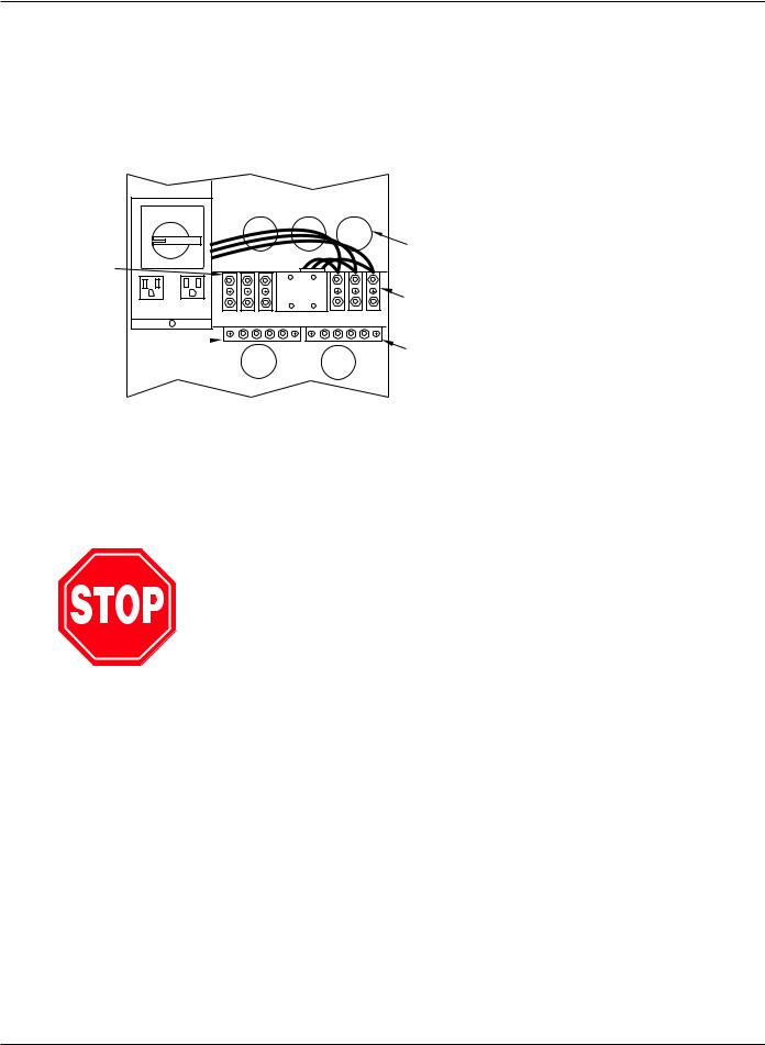
STEP 3 Connect the Output to the Distribution Panel (Load)
The Galaxy 3000 UPS system offers a standard 208 VAC output voltage. Optionally, a transformer can be provided in an auxiliary cabinet that will provide 240 VAC, 480 VAC or 600 VAC for the output.
Figure QS-3: Terminal Blocks.
TRANSFER
NB
OY
R |
P |
KNOCKOUTS |
M |
A |
|
A |
S |
|
L |
S |
|
UPS OUTPUT |
|
|
(TB2) |
|
|
|
|
(OPTIONAL) |
|
|
MAIN INPUT |
J3 |
J4 |
CONNECTIONS |
|
|
|
|
TB2 OUTPUT |
TB1 INPUT |
|
|
(TB1) |
OUTPUT NEUTRAL  TERMINAL POST
1/4-20 X 3/4" DIA.
INPUT NEUTRAL TERMINAL POST 1/4-20 X 3/4" DIA.
FRONT VIEW
The output from either the Galaxy 3000 cabinet or from the external auxiliary transformer cabinet should be wired to the existing power distribution panel, or to an appropriate power management panel.
The output from the Galaxy 3000 UPS system should be connected to the left most set of terminal blocks (see Figure QS-3.).
STEP 4 Call MGE UPS Systems for Field Engineer Service
Call MGE Field Engineer Service support at 800 438-7373 to finalize the installation of the unit.
STEP 5 Arrival of MGE Field Engineer
The MGE Field Engineer will finalize the initial Galaxy 3000 UPS start-up. To insure a successful installation and reliable UPS service, the MGE Field Engineer will verify all of the installation connections, fusing, and then will examine the extensive set of Galaxy 3000 UPS personalization parameters to insure that the operation of the UPS exactly matches your installation requirements.
QS—4 |
Quick Start |
86-172010-00 C05 |

Installation and User Manual
Operator Interface Panel
The Galaxy 3000 system is simple to operate and yet provides a wealth of continuous monitoring and diagnostic features to insure the proper operation of the unit.
Operators gain access to information in the Galaxy 3000 system through the operator interface. This display panel and keyboard is conveniently located on the front of the UPS cabinet see Figure QS-4.
Operator Interface - The Galaxy 3000 Operator Interface provides an easy to use method to access and control the Galaxy features. Through the use of four (4) "soft" keys and four (4) dedicated purpose keys, the operators can quickly move through the available displays, and control the performance of the unit.
Figure QS-4: Operator Input Panel.
OPERATOR
INPUT PANEL
|
Galaxy 3000 |
|
|
|
|
COLOR DISPLAY |
|
|
|
|
|
(Screen Saver shown) |
|
|
SOFT KEYS |
||
|
|
|
1 |
= |
Scroll up |
|
|
|
2 |
= |
Scroll down |
|
|
|
3 |
= View Alarm messages |
|
|
|
? |
4 |
= Detail of Alarm message |
|
|
|
|
|
|
|
( 1 |
2 3 4 |
( |
|
|
|
MAIN MENU KEY |
|
|
ONLINE HELP KEY |
||
|
|
|
|||
!!
LED INDICATORS |
INVERTER OFF/STOP KEY |
|
INVERTER ON/START KEY |
NOTE:SEE DETAILS OF OPERATOR PANEL IN SEXTION 3.3
GALAXY 3000
FRONT VIEW
86-172010-00 C05 |
Quick Start |
QS—5 |
Galaxy 3000 10-30kVA
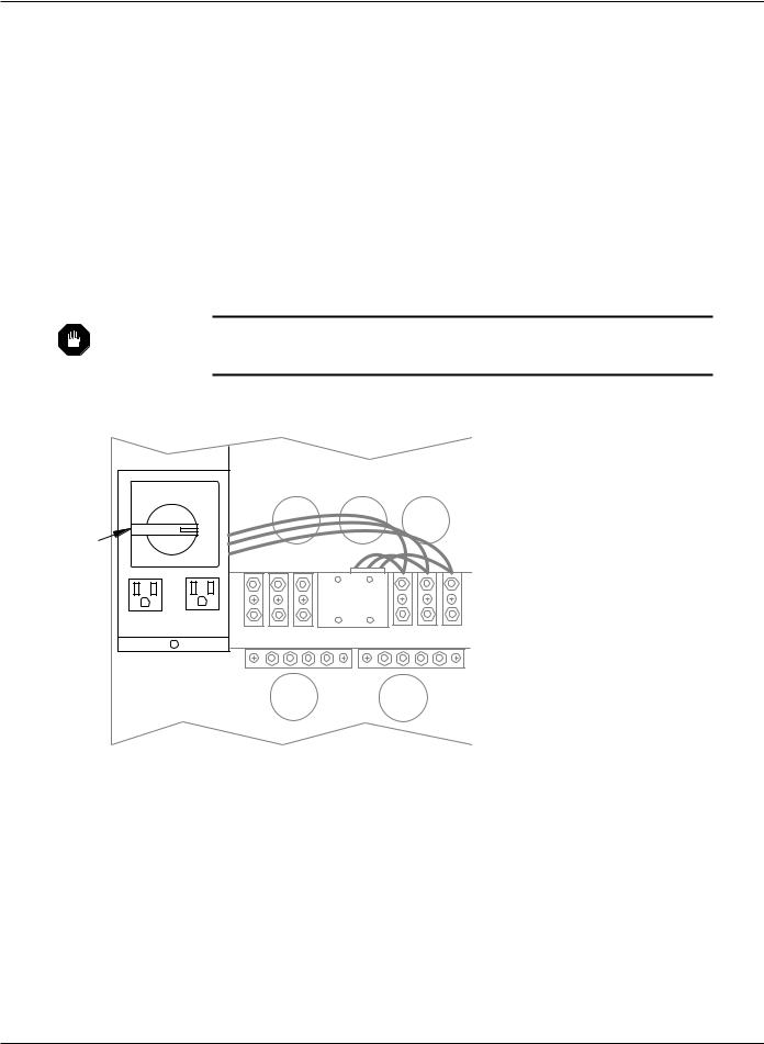
Quick Start Notes
If AC power is required on site prior to the arrival of the MGE Field Engineer, the following procedure will provide the AC power without powering the UPS. Any questions about this procedure contact the MGE Field Service support line at 800 438-7373.
A.Insure that the Bypass Switch is in the BYPASS position.
B.Insure that the battery breaker, QF1, is open.
C.Close the input power breaker to energize the AC power.
D.At this point, power will be available for site usage until the UPS is properly commissioned.
E.Upon arrival of the MGE Field Service Engineer, the main power must be disconnected so that a safe and proper commissioning of the unit may be accomplished.
WARNING Do not, under any circumstance, rotate the switch to the TRANSFER or NORMAL position, or close the battery breaker, QF1, until the unit has been commissioned by an MGE Field Engineer.
Figure QS-5: Bypass Switch Set to Bypass Mode.
TRANSFER
|
N |
B |
|
|
O |
Y |
|
|
R |
P |
|
BYPASS |
M |
A |
|
A |
S |
||
SWITCH |
|||
|
L |
S |
J3 J4
TB2 OUTPUT |
TB1 INPUT |
FRONT VIEW
QS—6 |
Quick Start |
86-172010-00 C05 |
 Loading...