


w w w . m g e u p s . c o m
Graphical Command Center
User Manual

Graphical Command Center
I M P O R TA N T S A F E T Y I N S T R U C T I O N S
SAVE THESE INSTRUCTIONS – This manual contains important instructions for all GCC's that must be followed during operation of the equipment.
WARNING: |
Opening enclosures expose hazardous voltages. Always refer |
|
service to qualified personnel only. |
ATTENTION: L'ouverture des cabinets expose des tensions dangereuses. Assurez-vous toujours que le service ne soit fait que par des personnes qualifiees.
WARNUNG!: Das öffnen der Gehäuse legen gefährliche Spannungen bloss. Service sollte immer nur von qualifizierten Personal durchgeführt werden.
WARNING: |
As standards, specifications, and designs are subject to |
|
change, please ask for confirmation of the information given |
|
in this publication. |
ATTENTION: Comme les normes, spécifications et produits peuvent changer, veuillez demander confirmation des informations contenues dans cette publication.
..
WARNUNG!: Normen, Spezifizierungen und Pläne unterliegen Anderungen. Bitte verlangen Sie eine Bestätigung über alle Informationen, die in dieser Ausgabe gemacht wurden.
page ii |
Important Safety information |

User Manual
Graphical Command Center
User Manual
For service call
1-800-438-7373
86-132204-00 A00 01/03
Copyright © 2002 MGE UPS SYSTEMS, Inc. All rights reserved. Printed in U.S.A.
MGE UPS SYSTEMS, Inc. 1660 Scenic Avenue Costa Mesa, CA 92626 (714) 557-1636
page iii

Graphical Command Center
Graphical Command Center
User Manual
Warranty
The liability of MGE UPS SYSTEMS, Inc. hereunder is limited to replacing or repairing at MGE UPS SYSTEMS, Inc.’s factory or on the job site at MGE UPS SYSTEMS, Inc.’s option, any part or parts which are defective, including labor, for a period of 12 months from the date of purchase. The MGE UPS SYSTEMS, Inc. shall have the sole right to determine if the parts are to be repaired at the job site or whether they are to be returned to the factory for repair or replacement. All items returned to MGE UPS SYSTEMS, Inc. for repair or replacement must be sent freight prepaid to its factory. Purchaser must obtain MGE UPS SYSTEMS, Inc.’s Return Materials Authorization prior to returning items. The above conditions must be met if warranty is to be valid. MGE UPS SYSTEMS, Inc. will not be liable for any damage done by unauthorized repair work, unauthorized replacement parts, from any misapplication of the item, or for damage due to accident, abuse, or Act of God.
In no event shall the MGE UPS SYSTEMS, Inc. be liable for loss, damage, or expense directly or indirectly arising from the use of the units, or from any other cause, except as expressly stated in this warranty. MGE UPS SYSTEMS, Inc. makes no warranties, express or implied, including any warranty as to merchantability or fitness for a particular purpose or use. MGE UPS SYSTEMS, Inc. is not liable for and Purchaser waives any right of action it has or may have against MGE UPS SYSTEMS, Inc. for any consequential or special damages arising out of any breach of warranty, and for any damages Purchaser may claim for damage to any property or injury or death to any person arising out of its purchase of the use, operation or maintenance of the product. MGE UPS SYSTEMS, Inc. will not be liable for any labor subcontracted or performed by Purchaser for preparation of warranted item for return to MGE UPS SYSTEMS, Inc.’s factory or for preparation work for field repair or replacement. Invoicing of MGE UPS SYSTEMS, Inc. for labor either performed or subcontracted by Purchaser will not be considered as a liability by the MGE UPS SYSTEMS, Inc.
This warranty shall be exclusive of any and all other warranties express or implied and may be modified only by a writing signed by an officer of the MGE UPS SYSTEMS, Inc. This warranty shall extend to the Purchaser but to no one else. Accessories supplied by MGE UPS SYSTEMS, Inc., but manufactured by others, carry any warranty the manufacturers have made to MGE UPS SYSTEMS, Inc. and which can be passed on to Purchaser.
MGE UPS SYSTEMS, Inc. makes no warranty with respect to whether the products sold hereunder infringe any patent, U.S. or foreign, and Purchaser represents that any specially ordered products do not infringe any patent. Purchaser agrees to indemnify and hold MGE UPS SYSTEMS, Inc. harmless from any liability by virtue of any patent claims where Purchaser has ordered a product conforming to Purchaser’s specifications, or conforming to Purchaser’s specific design.
Purchaser has not relied and shall not rely on any oral representation regarding the Product sold hereunder and any oral representation shall not bind MGE UPS SYSTEMS, Inc. and shall not be part of any warranty.
There are no warranties which extend beyond the description on the face hereof. In no event shall MGE UPS SYSTEMS, Inc. be responsible for consequential damages or for any damages except as expressly stated herein.
Service and Factory Repair - Call 1 - 800 - 438 - 7373
Direct questions about the operation, repair, or servicing of this equipment to MGE UPS SYSTEMS, Inc. Technical Support Services. Include the part number and serial number of the unit in any correspondence. Should you require factory service for your equipment, contact MGE UPS SYSTEMS, Inc. Technical Support Services and obtain a Return Materials Authorization (RMA) prior to shipping your unit. Never ship equipment to MGE UPS SYSTEMS, Inc. without first obtaining an RMA.
Proprietary Rights Statement
The information in this manual is the property of MGE UPS SYSTEMS, Inc., and represents a proprietary article in which MGE UPS SYSTEMS, Inc., retains any and all patent rights, including exclusive rights of use and/or manufacture and/or sale. Possession of this information does not convey any permission to reproduce, print, or manufacture the article or articles shown herein. Such permission may be granted only by specific written authorization, signed by an officer of MGE UPS SYSTEMS, Inc.
IBM, PC-AT, ES/9000, and AS/400 are trademarks of International Business Machines Corporation. MGE and MGE UPS SYSTEMS are trademarks of MGE UPS SYSTEMS, Inc. Other trademarks that may be used herein are owned by their respective companies and are referred to in an editorial fashion only.
Revision History
Graphical Command Center, User Manual |
|
|
|
86-132204-00 |
|
|
|
Copyright © 2003 MGE UPS SYSTEMS, Inc. |
All rights reserved |
Printed in U.S.A. |
|
Revision: A00 |
ECN # 003098 |
01/2003 |
|
page iv |
Warranty Information |

User Manual
How To Use This Manual:
This manual is designed for ease of use and easy location of information.
To quickly find the meaning of terms used within the text, look to the Glossary.
To quickly find a specific topic, look at the Table of Contents.
This manual uses icons with text to convey important information.
The icons come in four varieties.
WARNING: |
Indicates information provided to protect the User and service |
|
personnel against safety hazards and possible equipment |
|
damage. |
|
|
|
|
CAUTION: |
Indicates information provided to protect the User and serv- |
|
ice personnel against possible equipment damage. |
|
|
|
|
NOTE: |
Indicates information provided as an operating tip or an |
|
equipment feature. |
|
|
|
|
IMPORTANT: Indicates information provided as an operating instruction or as a tip.
NOTE: |
A version of this manual is available in color on the MGE |
|
website, www.mgeups.com. |
|
|
|
|
How To Use This Manual |
page v |

Graphical Command Center
(This page left blank intentionally)
page vi

|
|
|
|
|
User Manual |
|
|
|
|
|
|
|
|
|
|
|
C o n t e n t s |
|
|
|
section |
description . . . . . . . . . . . . . . . . . . . . . . . . . . . |
. . . . . . . . . . .page |
|
|
|
|
Important Safety Instructions . . . . . . . . . . . . . . |
Inside Front Cover |
|
|
|
|
Warranty . . . . . . . . . . . . . . . . . . . . . . . . . . . . . |
. . . . . . . . . . . . .iii |
|
|
|
|
Revision History . . . . . . . . . . . . . . . . . . . . . . . |
. . . . . . . . . . . . .iii |
|
|
|
|
How to Use This Manual . . . . . . . . . . . . . . . . . |
. . . . . . . . . . . . .iv |
|
|
|
|
Table of Contents . . . . . . . . . . . . . . . . . . . . . . . |
. . . . . . . . . . . .c i |
Section |
1 |
Introduction |
|
|
|
|
|
|
section |
description . . . . . . . . . . . . . . . . . . . . . . . . . . . . |
. . . . . . . . . .page |
|
|
|
1.0 |
Scope . . . . . . . . . . . . . . . . . . . . . . . . . . . . . . . . |
. . . . . . . . . . .1-1 |
|
|
|
1.1 |
Reference Manuals . . . . . . . . . . . . . . . . . . . . . . |
. . . . . . . . . . .1-1 |
|
|
|
1.2 |
Section Descriptions . . . . . . . . . . . . . . . . . . . . . |
. . . . . . . . . . .1-1 |
|
|
|
1.3 |
GCC System Overview . . . . . . . . . . . . . . . . . . . |
. . . . . . . . . . .1-2 |
|
|
|
1.4 |
Keypad . . . . . . . . . . . . . . . . . . . . . . . . . . . . . . . |
. . . . . . . . . . .1-3 |
|
|
|
1.5 |
GCC Configurations . . . . . . . . . . . . . . . . . . . . . . |
. . . . . . . . . . .1-4 |
Section |
2 |
GCC Setup |
|
|
|
|
|
|
section |
description . . . . . . . . . . . . . . . . . . . . . . . . . . . . |
. . . . . . . . . .page |
|
|
|
2.0 |
Scope . . . . . . . . . . . . . . . . . . . . . . . . . . . . . . . . |
. . . . . . . . . . .2-1 |
|
|
|
2.1 |
GCC Setup Screen . . . . . . . . . . . . . . . . . . . . . . |
. . . . . . . . . . .2-1 |
|
|
|
2.1.1 |
Enter Setup Screen . . . . . . . . . . . . . . . . . . . . . . |
. . . . . . . . . . .2-1 |
|
|
|
2.1.2 |
Identification Setup Screen . . . . . . . . . . . . . . . . |
. . . . . . . . . . .2-2 |
|
|
|
2.1.3 |
Change Password . . . . . . . . . . . . . . . . . . . . . . . |
. . . . . . . . . . .2-5 |
|
|
|
2.1.4 |
Control Panel . . . . . . . . . . . . . . . . . . . . . . . . . . |
. . . . . . . . . . .2-6 |
Contents |
page c i |

Graphical Command Center
Section |
3 |
GCC Screens |
|
|
|
|
|
section |
description . . . . . . . . . . . . . . . . . . . . . . . . . . . . . . . . . . . . . . . . . . |
. page |
|
|
|
3.0 |
|
Scope . . . . . . . . . . . . . . . . . . . . . . . . . . . . . . . . . . . . . . . . . |
. .3-1 |
|
|
3.1 |
|
GCC Menu Structure . . . . . . . . . . . . . . . . . . . . . . . . . . . . . . |
. .3-1 |
|
|
3.2 |
|
Main Menu Screen . . . . . . . . . . . . . . . . . . . . . . . . . . . . . . . . |
.3-2 |
|
|
3.2.1 |
|
Menu Buttons . . . . . . . . . . . . . . . . . . . . . . . . . . . . . . . . . . . . |
.3-2 |
|
|
3.2.2 |
|
UPS Status Panel . . . . . . . . . . . . . . . . . . . . . . . . . . . . . . . . . |
.3-4 |
|
|
3.3 |
|
System Main Menu Screen . . . . . . . . . . . . . . . . . . . . . . . . . . |
.3-5 |
|
|
3.4 |
|
Inverter Screen . . . . . . . . . . . . . . . . . . . . . . . . . . . . . . . . . . . |
.3-6 |
|
|
3.5 |
|
Rectifier Screen . . . . . . . . . . . . . . . . . . . . . . . . . . . . . . . . . . . |
.3-7 |
|
|
3.6 |
|
Single-Module Load Screen . . . . . . . . . . . . . . . . . . . . . . . . . . |
.3-8 |
|
|
3.7 |
|
Multi-Module Load UPS Screen . . . . . . . . . . . . . . . . . . . . . . . |
.3-9 |
|
|
3.8 |
|
Multi-Module System Load Screen . . . . . . . . . . . . . . . . . . . . . |
3-10 |
|
|
3.9 |
|
Single-Module Battery Screen . . . . . . . . . . . . . . . . . . . . . . . . |
3-11 |
|
|
3.10 |
|
Multi-Module Battery Screen . . . . . . . . . . . . . . . . . . . . . . . . . |
3-12 |
|
|
3.11 |
|
Online Trending Screen . . . . . . . . . . . . . . . . . . . . . . . . . . . . . |
3-13 |
|
|
3.11.1 |
Online Trending Selection Menu . . . . . . . . . . . . . . . . . . . . . . |
3-13 |
|
|
|
3.11.2 |
UPS Status Menu . . . . . . . . . . . . . . . . . . . . . . . . . . . . . . . . . |
3-13 |
|
|
|
3.12 |
|
Input Screen . . . . . . . . . . . . . . . . . . . . . . . . . . . . . . . . . . . . . |
3-14 |
Section |
4 |
GCC Mimic Diagrams |
|
||
|
|
section |
description . . . . . . . . . . . . . . . . . . . . . . . . . . . . . . . . . . . . . . . . . . . |
page |
|
|
|
4.0 |
|
Scope . . . . . . . . . . . . . . . . . . . . . . . . . . . . . . . . . . . . . . . . . . |
.4-1 |
|
|
4.1 |
|
Color Status Indicator . . . . . . . . . . . . . . . . . . . . . . . . . . . . . . |
.4-1 |
|
|
4.2 |
|
Power Flow . . . . . . . . . . . . . . . . . . . . . . . . . . . . . . . . . . . . . . |
.4-1 |
|
|
4.3 |
|
Single-Module UPS Online . . . . . . . . . . . . . . . . . . . . . . . . . . |
.4-2 |
|
|
4.4 |
|
Single-Module UPS On Bypass . . . . . . . . . . . . . . . . . . . . . . . |
.4-3 |
|
|
4.5 |
|
Single-Module UPS On Battery . . . . . . . . . . . . . . . . . . . . . . . |
.4-4 |
|
|
4.6 |
|
S-M UPS Battery CB Open . . . . . . . . . . . . . . . . . . . . . . . . . . |
.4-5 |
|
|
4.7 |
|
Multi-Module Online . . . . . . . . . . . . . . . . . . . . . . . . . . . . . . . . |
.4-6 |
|
|
4.8 |
|
Multi-Module 1 UPS on Battery . . . . . . . . . . . . . . . . . . . . . . . |
.4-7 |
|
|
4.9 |
|
Multi-Module on Bypass . . . . . . . . . . . . . . . . . . . . . . . . . . . . . |
.4-8 |
|
|
4.10 |
|
Multi-Module Test and Maintenance Mode on UPS . . . . . . . . |
.4-9 |
|
|
4.11 |
|
Multi-Module Test and Maintenance Mode on Bypass . . . . . . |
4-10 |
|
|
4.12 |
|
Multi-Module Transfer Mode . . . . . . . . . . . . . . . . . . . . . . . . . . |
4-11 |
|
|
4.13 |
|
Multi-Module Communication Fault . . . . . . . . . . . . . . . . . . . . |
4-12 |
page c ii |
Contents |

User Manual
Section |
5 |
GCC Alarms |
|
|
|
|
section |
description . . . . . . . . . . . . . . . . . . . . . . . . . . . . . . . . . . . . . . . . . . |
. page |
|
|
5.0 |
Scope . . . . . . . . . . . . . . . . . . . . . . . . . . . . . . . . . . . . . . . . . |
. .5-1 |
|
|
5.1 |
Alarm and Event System . . . . . . . . . . . . . . . . . . . . . . . . . . . |
. .5-1 |
|
|
5.2 |
Alarms and Events Lists . . . . . . . . . . . . . . . . . . . . . . . . . . . . |
.5-1 |
|
|
5.3 |
Alarm/Event Present Log Screen . . . . . . . . . . . . . . . . . . . . . . |
.5-2 |
|
|
5.4 |
Alarm/Event History Log Screen . . . . . . . . . . . . . . . . . . . . . . |
.5-4 |
Section |
6 |
GCC Troubleshooting |
|
|
|
|
section |
description . . . . . . . . . . . . . . . . . . . . . . . . . . . . . . . . . . . . . . . . . . . |
page |
|
|
6.0 |
Scope . . . . . . . . . . . . . . . . . . . . . . . . . . . . . . . . . . . . . . . . . . |
.6-1 |
|
|
6.1 |
Communications and Configuration . . . . . . . . . . . . . . . . . . . . |
.6-1 |
|
|
6.2 |
RS232/RS485 Interface Connections . . . . . . . . . . . . . . . . . . . |
.6-1 |
|
|
6.2.1 |
Twisted Pair Connection using Terminal Blocks . . . . . . . . . . . |
.6-1 |
|
|
6.3 |
Communications Port Switch Settings . . . . . . . . . . . . . . . . . . |
.6-2 |
|
|
6.4 |
Communications Port 2 Personalization . . . . . . . . . . . . . . . . . |
.6-4 |
|
|
6.4.1 |
Slave Address for Single-Module . . . . . . . . . . . . . . . . . . . . . . |
.6-5 |
|
|
6.4.2 |
Slave Address for Multi-Module with |
|
GCC in SSC Cabinet . . . . . . . . . . . . . . . . . . . . . . . . . . . . . . . .6-5
6.4.3Slave Address for Multi-Module with
|
GCC in Each Cabinet . . . . . . . . . . . . . . . . . . . . . . . . . . . . . . |
.6-6 |
6.5 |
GCC Port Connectors and Future Product Updates . . . . . . . . |
.6-6 |
6.6 |
RS232/RS485 Interface Converter . . . . . . . . . . . . . . . . . . . . . . |
6-7 |
6.6.1 |
Switch Setting . . . . . . . . . . . . . . . . . . . . . . . . . . . . . . . . . . . . |
6-7 |
6.7 |
Auto Start . . . . . . . . . . . . . . . . . . . . . . . . . . . . . . . . . . . . . . . . |
6-9 |
6.8 |
GCC Identification Label . . . . . . . . . . . . . . . . . . . . . . . . . . . . . |
6-9 |
6.9 |
Rebooting . . . . . . . . . . . . . . . . . . . . . . . . . . . . . . . . . . . . . . . . |
6-9 |
Glossary |
. . . . . . . . . . . . . . . . . . . . . . . . . . . . . . . . . . . . . . . . . . . . . . . . |
g-1 |
Index |
. . . . . . . . . . . . . . . . . . . . . . . . . . . . . . . . . . . . . . . . . . . . . . . . |
I-1 |
Contents |
page c iii |

Graphical Command Center
Figures
number |
description . . . . . . . . . . . . . . . . . . . . . . . . . . . . . . . . . . . . . . |
page |
1-1 |
Keypad Alphanumeric Characters . . . . . . . . . . . . . . . . . . . . . |
.1-3 |
1-2 |
S-M Configuration , 1 GCC per Module |
|
|
(800 kVA UPS System Shown) . . . . . . . . . . . . . . . . . . . . . . . |
.1-4 |
1-3 |
M-M Configuration , 1 GCC per Module |
|
|
(800 kVA UPS System Shown) . . . . . . . . . . . . . . . . . . . . . . . |
.1-5 |
1-4 |
M-M Configuration , 1 GCC per System Located on the SSC |
|
|
(800 kVA UPS System Shown) . . . . . . . . . . . . . . . . . . . . . . . |
.1-5 |
2-1 |
Enter Setup Screen . . . . . . . . . . . . . . . . . . . . . . . . . . . . . . . |
.2-1 |
2-2 |
S-M Identification Setup Screen . . . . . . . . . . . . . . . . . . . . . . |
.2-3 |
2-3 |
M-M Identification Setup Screen . . . . . . . . . . . . . . . . . . . . . . |
.2-3 |
2-4 |
M-M System Configuration Screen . . . . . . . . . . . . . . . . . . . . |
.2-4 |
2-5 |
The Change Password Screen . . . . . . . . . . . . . . . . . . . . . . . |
.2-5 |
2-6 |
Date and Time Icon Screen . . . . . . . . . . . . . . . . . . . . . . . . . |
.2-6 |
3-1a |
S-M Menu Screen . . . . . . . . . . . . . . . . . . . . . . . . . . . . . . . . . |
.3-2 |
3-1b |
M-M Menu Screen . . . . . . . . . . . . . . . . . . . . . . . . . . . . . . . . |
.3-3 |
3-2 |
Main Menu Screen . . . . . . . . . . . . . . . . . . . . . . . . . . . . . . . . |
.3-4 |
3-3 |
M-M System Main Menu Screen . . . . . . . . . . . . . . . . . . . . . . |
.3-5 |
3-4 |
Inverter Screen . . . . . . . . . . . . . . . . . . . . . . . . . . . . . . . . . . . |
.3-6 |
3-5 |
Rectifier Screen . . . . . . . . . . . . . . . . . . . . . . . . . . . . . . . . . . |
.3-7 |
3-6 |
Single-Module Load Screen . . . . . . . . . . . . . . . . . . . . . . . . . |
.3-8 |
3-7 |
M-M Load UPS Screen . . . . . . . . . . . . . . . . . . . . . . . . . . . . . |
.3-9 |
3-8 |
M-M System Load Screen . . . . . . . . . . . . . . . . . . . . . . . . . . . |
3-10 |
3-9 |
S-m Battery Screen . . . . . . . . . . . . . . . . . . . . . . . . . . . . . . . |
.3-11 |
3-10 |
M-M Battery Screen . . . . . . . . . . . . . . . . . . . . . . . . . . . . . . . |
3-12 |
3-11 |
Online, Trending Screen . . . . . . . . . . . . . . . . . . . . . . . . . . . . |
3-13 |
3-12 |
Input Screen . . . . . . . . . . . . . . . . . . . . . . . . . . . . . . . . . . . . . |
3-14 |
4-1 |
S-M UPS Online . . . . . . . . . . . . . . . . . . . . . . . . . . . . . . . . . . |
.4-2 |
4-2 |
S-M UPS on Bypass . . . . . . . . . . . . . . . . . . . . . . . . . . . . . . . |
.4-3 |
4-3 |
S-M UPS on Battery . . . . . . . . . . . . . . . . . . . . . . . . . . . . . . . |
.4-4 |
4-4 |
S-M Battery CB Open . . . . . . . . . . . . . . . . . . . . . . . . . . . . . . |
.4-5 |
4-5 |
M-M UPS Online . . . . . . . . . . . . . . . . . . . . . . . . . . . . . . . . . |
.4-6 |
4-6 |
M-M UPS on Battery . . . . . . . . . . . . . . . . . . . . . . . . . . . . . . . |
.4-7 |
4-7 |
M-M UPS on Bypass . . . . . . . . . . . . . . . . . . . . . . . . . . . . . . |
.4-8 |
4-8 |
M-M Test/Maintenance Mode on UPS . . . . . . . . . . . . . . . . . . |
.4-9 |
4-9 |
M-M Test/Maintenance Mode on Bypass . . . . . . . . . . . . . . . . |
4-10 |
4-10 |
M-M Transfer Mode on UPS . . . . . . . . . . . . . . . . . . . . . . . . |
.4-11 |
4-11 |
M-M Communications Fault . . . . . . . . . . . . . . . . . . . . . . . . . |
4-12 |
page c iv |
Contents |
User Manual
|
Figures (continued) |
|
|
|
number |
description . . . . . . . . . . . . . . . . . . . . . . . . . . . . . . . . . . . . . |
. page |
|
5-1 |
Alarm/Event Present Log Screen . . . . . . . . . . . . . . . . . . . . |
. .5-3 |
|
5-2 |
Alarm/Event History Log Screen . . . . . . . . . . . . . . . . . . . . . . |
.5-5 |
|
5-3 |
Clear Alarm/Event Log Password Screen . . . . . . . . . . . . . . . |
.5-6 |
|
5-4 |
Clear Log Screen . . . . . . . . . . . . . . . . . . . . . . . . . . . . . . . . . |
.5-6 |
|
6-1 |
S-M RS485 Interface Connections with GCC . . . . . . . . . . . . |
.6-1 |
|
6-2 |
M-M Rs232/RS485 Interface Connections with GCC . . . . . . |
.6-2 |
|
6-3 |
GTCZ/RAUZ1 & GTQZ/RAUZ2 PCB Config. Settings . . . . . . |
.6-3 |
|
6-4 |
S-M Slave Address Settings . . . . . . . . . . . . . . . . . . . . . . . . . |
.6-5 |
|
6-5 |
M-M with GCC Slave Address Settings . . . . . . . . . . . . . . . . . |
.6-5 |
|
6-6 |
M-M with GCC in Each Cabinet Slave Address Settings . . . . .6-6 |
|
|
6-7 |
Converters Location Dip Switch S1 . . . . . . . . . . . . . . . . . . . . |
.6-7 |
|
6-8 |
Converters Location Dip Switch S2 . . . . . . . . . . . . . . . . . . . . |
.6-7 |
|
6-9 |
Converter Switch Access . . . . . . . . . . . . . . . . . . . . . . . . . . . |
.6-8 |
|
6-10 |
Dip Switches . . . . . . . . . . . . . . . . . . . . . . . . . . . . . . . . . . . . |
.6-8 |
|
Tables |
|
|
|
number |
description . . . . . . . . . . . . . . . . . . . . . . . . . . . . . . . . . . . . . . |
page |
|
6-1 |
Two-Module Communications Port Switch Settings . . . . . . . . |
.6-4 |
|
6-2 |
M-M with 1 GCC in each cabinet, the slave address settings . |
.6-6 |
|
6-3 |
Converter Dip Switch Settings . . . . . . . . . . . . . . . . . . . . . . . . |
.6-8 |
|
|
|
|
|
|
|
|
Contents |
page c v |

Graphical Command Center
(This page left blank intentionally)
page c vi

User Manual
I n t r o d u c t i o n
1.0Scope
This section is a general introduction and overview of the MGE Graphical Command Center (GCC).
1.1Reference Manuals
86-132203-00 |
EPS 8000 625-800kVA User Manual, Single-Module |
|
86-132202-00 |
EPS 8000 625-800kVA User Manual, Parallel System |
|
86-132201-55 |
EPS 8000 625-800kVA Installation Manual, Single and Parallel Systems, 50/60 Hz |
|
86-130033-00 |
EPS 6000 |
User Manual, 150-750kVA Single-Module |
86-130034-00 |
EPS 6000 |
User Manual, 150-750kVA Multi-Module |
86-131107-00 |
EPS 6000 |
User Manual, Parallel-Connected Single UPS Units |
6739390XU |
EPS 6000 |
Communication Manual, 50/60 Hz |
1.2Section Descriptions
This manual is divided into six sections:
Section 1 — Introduction
This section is a general introduction and overview of the MGE Graphical Command Center (GCC).
Section 2— GCC Setup
This section guides the User through the GCC login and custom configuration screens.
Section 3 — GCC Screens
This section describes each screen, the menu buttons, and how to navigate from screen to screen.
Section 4— GCC Mimic Diagrams
This section provides GCC mimic diagrams representing the common status and fault modes.
Section 5 — GCC Alarms
This section describes the captured alarms and events, including how to acknowledge and clear the alarm history log.
Section 6 — GCC Troubleshooting
This section contains a troubleshooting guide to assist the User with any communication and configuration problems.
A Glossary in the rear of this manual provides definitions of terms used within the text.
Introduction |
page 1 — 1 |

Graphical Command Center
1.3GCC System Overview
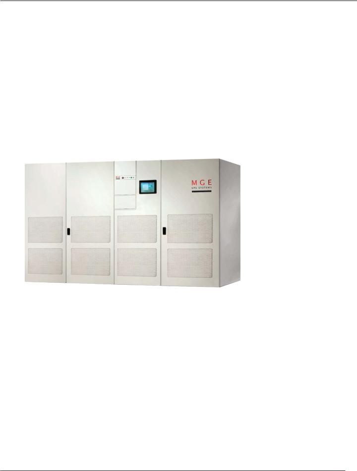
The GCC functions as the monitoring program for your system. The intention of the GCC is to operate only as an aid to the existing indicators and controls. It is only intended as a display device and will not be used for any control purposes. The GCC is factory installed and tested before shipment, therefore, it is ready to use upon receipt.
When powering up the display a boot screen similar to what you see in starting a “Windows PC” appears. The display will proceed with a memory test and other prerequisites, then load the operating system, and finally the UPS monitoring software. The GCC is ready when showing the mimic diagram with the menu selection buttons.
The GCC uses a color liquid crystal display (LCD) with a touch sensitive screen. Touching the screen a single time will enable the User to enter the menu selection buttons or the icons on the mimic diagram. Double-clicking or touching the screen in two quick successions in a text box will enable the User to enter the Keypad of alphanumeric characters. Use of the keypad is required to enter or change the password.
WARNING: |
The touch screen can be damaged by sharp objects. Always |
|
use a soft object or the pad of your finger to navigate through |
|
the screens. |
|
|
|
|
page 1 — 2 |
Introduction |
PRELIMINARY COPY |
User Manual |
|
|
1.4Keypad
The Keypad opens by double-clicking inside any text box.
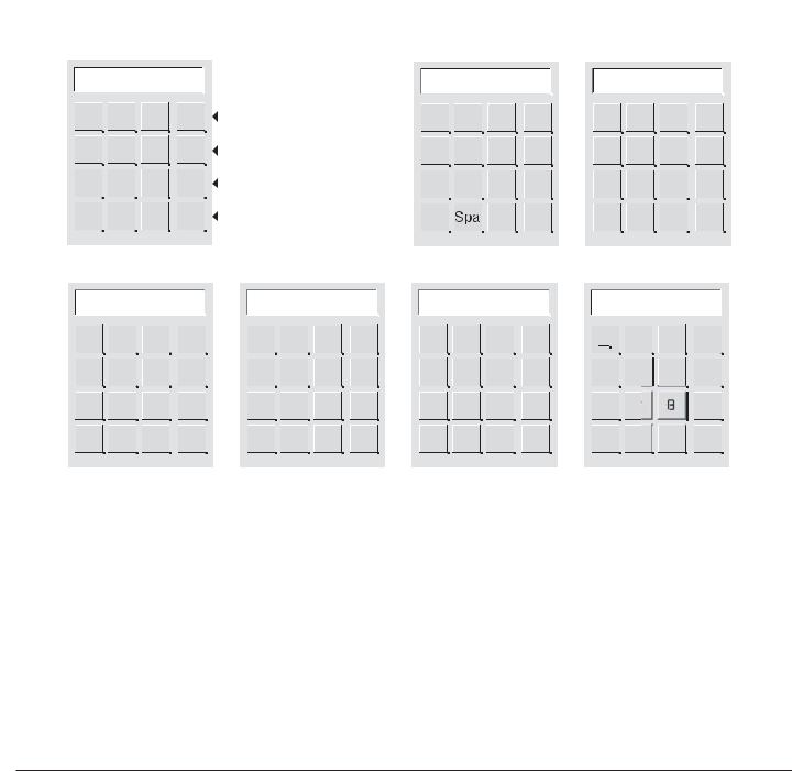
The alphanumeric Keypad provides access to normal keyboard characters, Decimal Point (.), Backspace (Bsp), Space (Spa), Caps (Cps) and other characters.
Use the “<-” and “->” keys to scroll to next group of keys. See Figure 1-1 for all the available keypads.
Press the “OK” key when done entering information. Use the “Esc” key to exit the keypad without saving information.
Figure 1-1: Keypad Alphanumeric Characters.
Keypad 1 |
Keypad 2 |
Keypad 3 |
UPS 1
2 |
3 |
OK |
OK |
a |
b |
c |
OK |
j |
k |
OK |
|
|
|
Will close values stored in field |
|
|
|
|
|
|
|
4 |
5 |
6 |
Esc |
Escape |
d |
e |
f |
Esc |
m |
n |
o |
Esc |
7 |
8 |
9 |
Bsp |
Backspace |
g |
h |
Bsp |
p |
q |
r |
Bsp |
0 |
|
+ |
/- |
> |
Scroll |
|
|
||||||
|
||||||
|
|
|
|
|
To next group |
Cps |
> |
> |
Cps Spa |
> |
> |
Keypad 4 |
|
Keypad 5 |
|
Keypad 6 |
|
Keypad 7 |
|
|
|
|
|
|
|
|
|
|
|
|
|
|
s |
t |
u |
OK |
# |
% |
OK |
@ |
( |
OK |
& |
OK |
v |
w |
x |
Esc |
\ |
$ |
Esc |
) |
? |
Esc |
[ |
] |
a |
Esc |
y |
z |
/ |
Bsp |
+ |
|
Bsp |
> |
< |
Bsp |
0 |
u |
|
Bsp |
Cps Spa |
> |
> |
Cps Spa |
> |
> |
Cps Spa |
> |
> |
Cps Spa |
> |
> |
||
Introduction |
page 1 — 3 |
Graphical Command Center
1.5GCC Configurations
Three separate series of mimic diagrams are available:
1.Single-Module (S-M)
2.Multi-Module (M-M)
3.Static Switch Cabinet (SSC)
The GCC is located on the UPS Module, the Static Switch Cabinet or both. A Single-Module UPS configuration is shown in Figure 1-2. A Multi-Module UPS and SSC with a GCC on each UPS is shown in Figure 1-3. A MultiModule UPS and SSC with one GCC on the SSC is shown in Figure 1-4.
Figure 1-2: S-M Configuration, 1 GCC per Module. (800kVA UPS system shown)
page 1 — 4 |
Introduction |

User Manual
Figure 1-3: M-M Configuration, 1 GCC per each Module and the SSC. (800kVA UPS system shown)
Figure 1-4: M-M Configuration, 1 GCC per system located on the SSC. (800kVA UPS system shown)
|
|
|
|
|
|
|
|
|
Introduction |
page 1 — 5 |
|

Graphical Command Center
(This page left blank intentionally)
page 1 — 6
User Manual
G C C S e t u p
2.0Scope
This section guides the User through the GCC login and custom configuration screens.
2.1GCC Setup Screens
The following GCC Setup screens are described in this section:
Enter Setup
Identification Setup, Single-Module
Identification Setup, Multi-Module
System Configuration, Multi-Module
Change Password
Control Panel
2.1.1Enter Setup Screen
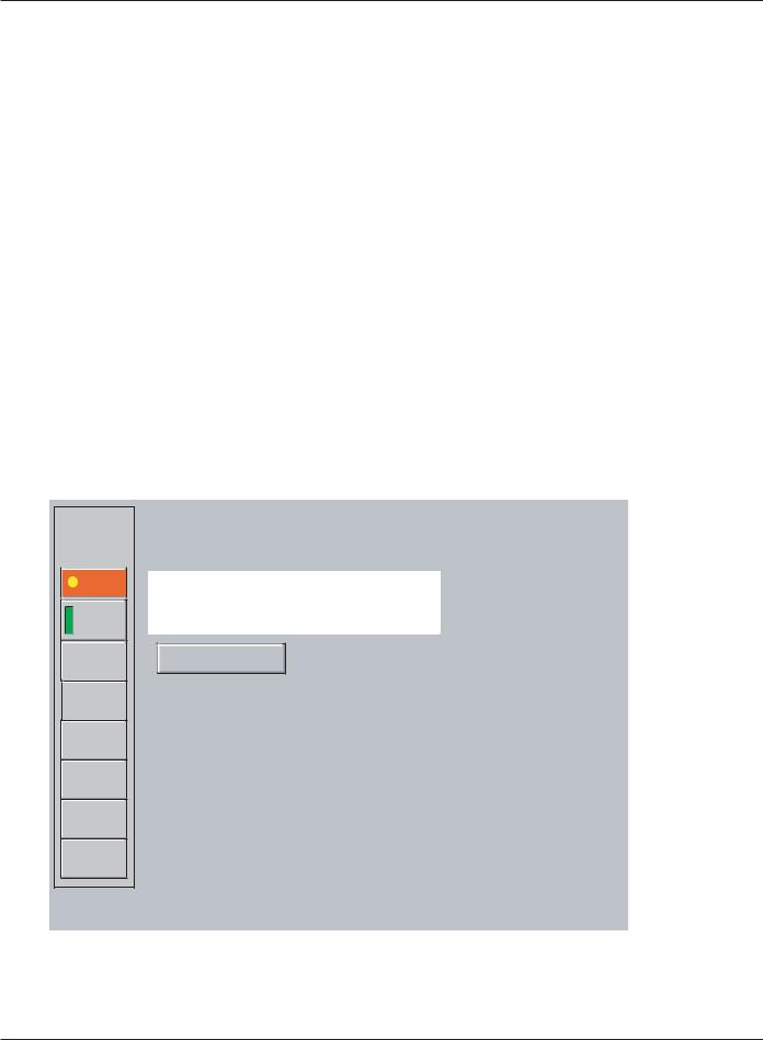
From the menu button click the “Setup” button to open theEnter Setup screen. Type the default password, ‘manager’, as shown in Figure 2-1. When the password is accepted, the Identification Setup screen opens and the User may change the password at that time or continue with the setup. Refer to section 1.4 Keypad for instructions to use the keypad.
Figure 2-1: Enter Setup Screen.
14:02:02 |
Enter Setup |
|
|
|
|
01/24/2003 |
|
Enter default |
|
|
|
Setup |
|
password |
|
|
|
ALARMS |
Password |
‘manager’ |
|
and press |
|
|
|
|
UPS 1 |
manager |
<Enter> |
Load |
|
|
|
|
|
Protected |
|
|
Inverter |
Enter |
|
Rectifier |
|
EXIT |
|
|
|
|
|
|
|
|
|
|
|
|
|
Load |
Battery
Online |
Trend |
Input
GCC Setup |
page 2 — 1 |

Graphical Command Center
2.1.2Identification Setup Screen
The Identification Setup screen is accessed from the Enter Setup screen when the password is entered. For a Single-Module the Identification Setup allows the User to modify the naming conventions for the UPS’s, circuit breakers, and inputs of the unit. For Multi-Module system the Identification Setup and System Configuration screens allow the User to modify the naming conventions. See Figure 2-2 for the Identification Setup for a SingleModule, and Figure 2-3 for a Multi-Module. See Figure 2-4 for the System Configuration screen for the Multi-Module.
The following is a description of the screen buttons.
1 |
Default names |
These are the text fields that appear on the mimic diagram. Change |
|
|
these text fields by double-clicking inside the box, and the keypad |
|
|
|
|
|
will appear allowing you to enter text. The default name (UPS Name |
|
|
= UPS 1) can be changed by double-clicking in the first text field and |
|
|
entering the UPS name. For instructions to use the keypad, see |
|
|
section 1.4 Keypad. |
|
Show CB’s/System CB Configuration |
Enable or disable circuit breakers in the system configuration. Green |
|
||
|
|
is enabled, and gray is disabled. If disabled, the breaker will not be |
|
|
|
|
|
shown in the mimic diagram. |
Battery Temp. Sensor present
Show battery Backup Time
Enable battery temperature monitoring (if that option was installed). Green is enabled, and gray is disabled.
Shows the UPS battery backup time. The UPS needs to have battery parameters programmed in order for this to work correctly. Refer to the UPS Manual, or contact Customer Service Support at
1-800-438-7373.
|
Alarm Pop-up Screen |
When enabled this button will set the Alarm/Event Present screen |
|
|
to open every time there is an unacknowledged alarm. Once |
|
|
|
|
|
enabled, the Alarm/Event Present screen will not close until all |
|
|
alarms/events are acknowledged. This may also be enabled in the |
|
|
Alarm/Event Present screen. |
|
Select if UPS is a 225, 300, 375 or 500KVA Disabling will filter alarms specific to 800 kVA class UPS’s. |
|
|
||
|
Change Password |
Selecting this menu button will open the Change Password screen. |
|
||
|
Refer to section 2.1.3 Change Password for the procedure. |
|
|
|
|
|
WARNING: |
A Password for the Control Panel and clearing the alarm his- |
|
|
tory is required. User should note password and keep in a |
|
|
secure location. |
 Control Panel
CAUTION:
Selecting this menu button will open the Control Panel screen. Refer to section 2.1.4 Control Panel to change the settings.
Use Caution in this menu as some settings can have adverse affects on the GCC operation.
Selects number of UPS’s in a Multi-Module System. Green is enabled and gray is disabled.
page 2 — 2 |
GCC Setup |
User Manual
Figure 2-2: S-M Identification Setup Screen.
07:34:18 |
Identification Setup |
|
|
01/24/2003 |
|
|
Setup |
|
1 |
|
|
|
|
ALARMS |
|
|
|
|
|
|
|
UPS Name |
UPS 1 |
|
|
|
|
UPS 1 |
Rectifier Input CB |
Q1 |
Show CB's |
|
|
|
Load |
|
|
|||
|
|
|
|
|||
|
Protected |
|
|
|
|
|
7 |
Change |
Bypass Input Breaker |
Q4S |
Q4S |
|
|
|
Q5N |
|
2 |
|
||
|
Password |
UPS Output Breaker |
Q5N |
|
||
8 |
Control |
System Bypass Breaker |
Q3BP |
Q3BP |
|
|
|
|
|
||||
|
Panel |
Battery Breaker |
QF1 |
|
|
|
|
|
|
|
|
||
|
|
Input 1 |
Utility 1 |
Battery Temp. |
3 |
|
|
|
|
|
|||
|
|
Input 2 |
Utility 2 |
Sensor present |
||
|
|
|
|
4 |
||
|
|
|
9 character max |
Show battery |
||
|
|
|
|
Backup time |
|
|
Alarm |
|
Set to have Alarm Screen automatically |
|
|
5 |
||
Popup |
|
||
|
open when new Alarm/Event happens |
||
Screen |
|
||
|
|
|
|
|
|
|
|
Select if UPS is a 225, 300, 375 or 500KVA  6
6
Figure 2-3: M-M Identification Setup Screen.
|
|
|
|
|
|
|
|
|
1 |
Identification Setup |
||||||
|
|
|
|
|
|
|
|
|
||||||||
|
07:34:18 |
|
|
|
||||||||||||
|
01/24/2003 |
|
|
|
|
|
|
Battery Breaker UPS 1 |
|
|
|
|||||
|
|
|
|
|
|
|
|
System Name |
|
System |
|
|
QF1 |
|
||
|
|
|
|
|
|
Setup |
|
|||||||||
|
|
|
|
|
|
|
|
|
|
|
|
Battery Breaker UPS 2 |
|
|
|
|
|
|
|
|
|
|
|
|
|
|
|
|
|
|
|
||
|
|
|
|
|
|
|
|
|
|
|
|
|
|
|
|
|
|
|
|
|
|
|
|
|
UPS 1 Name |
|
UPS 1 |
|
|
QF1 |
|
||
|
|
|
|
|
|
ALARMS |
|
|||||||||
|
|
|
|
|
|
|
|
|
|
|
|
Battery Breaker UPS 3 |
|
|
|
|
|
|
|
|
|
|
|
|
|
|
|
|
|
|
|
||
|
|
|
|
|
|
|
UPS 2 Name |
|
UPS 2 |
|
|
QF1 |
|
|||
|
|
|
|
|
|
|
|
|
|
|
|
|||||
|
|
|
|
|
|
|
|
|
|
|
|
|
Battery Breaker UPS 4 |
|
|
|
|
|
|
|
|
|
|
|
|
|
|
|
|
|
|
|
|
|
|
|
|
|
|
UPS 1 |
|
UPS 3 Name |
|
UPS 3 |
|
|
QF1 |
|
||
|
|
|
|
|
|
|
||||||||||
|
|
|
|
|
|
Load |
|
|
|
|
|
|
Battery Breaker UPS 5 |
|
|
|
|
|
|
|
|
|
|
|
|
|
|
|
|
|
|
||
|
|
|
|
|
|
|
UPS 4 Name |
|
UPS 4 |
|
|
QF1 |
|
|||
|
|
|
|
|
|
Protected |
|
|
|
|
|
|||||
|
|
|
|
|
|
|
|
|
|
|
|
Battery Breaker UPS 6 |
|
|
|
|
|
|
|
|
|
|
Change |
|
UPS 5 Name |
|
UPS 5 |
|
|
QF1 |
|
||
7 |
|
|
|
|
|
|
|
|
|
|
|
|
|
|
|
|
|
|
|
|
|
|
|
|
|
|
|
|
|
|
|
||
|
|
|
|
|
|
|
|
|
|
|
|
|
|
|
||
|
|
|
|
|
|
|
|
|
|
|
|
|
|
|
||
|
|
|
Password |
|
UPS 6 Name |
|
UPS 6 |
|
|
|
9 character max |
|||||
|
|
|
|
|
|
|
|
|
|
|
|
|
|
|
||
|
|
|
|
|
|
|
|
|
|
|
|
|
|
|||
8 |
Control |
UPS 1 Input CB |
Q1 |
Static Switch Input Brteaker |
Q4S |
|
|
||||
|
|
|
|
||
|
Panel |
UPS 2 Input CB |
Q1 |
Static Switch |
Q2S |
|
System |
UPS 3 Input CB |
Q1 |
System Output Breaker |
Q5N |
|
|
|
|||
|
|
|
|
|
|
|
Config. |
UPS 4 Input CB |
Q1 |
Maint. Bypass Breaker |
Q3BP |
|
|
UPS 5 Input CB |
Q1 |
Input 1 (UPS Input) |
Main 1 |
|
|
|
|
||
|
|
UPS 6 Input CB |
Q1 |
Input 2 (Bypass) |
Bypass |
|
|
|
|
||
|
|
UPS 1 Output CB |
Q5N |
|
|
|
|
UPS 2 Output CB |
Q5N |
|
|
|
|
UPS 3 Output CB |
Q5N |
|
|
|
|
UPS 4 Output CB |
Q5N |
|
|
|
|
UPS 5 Output CB |
Q5N |
|
|
|
|
UPS 6 Output CB |
Q5N |
|
|
Opens the System Configuration Screen.
GCC Setup |
page 2 — 3 |
Graphical Command Center
Figure 2-4: M-M System Configuration Screen.
|
15:14:01 |
|
Trend |
|
ALARMS |
|
System |
|
Load |
|
Protected |
|
Change |
7 |
Password |
8 |
Control |
|
Panel |
|
Back to |
|
Setup |
System CB |
|
2 |
|
Battery Temp. |
|
3 |
|
||||
|
|
|
|
||||||||
Config. |
|
|
|
|
|||||||
|
|
|
Sensor present |
|
|
|
|||||
|
|
|
|
|
|
|
|
|
|
|
|
|
|
|
|
|
|
|
|
|
|
|
|
Q4S |
|
|
|
|
UPS 1 |
|
UPS 4 |
|
|
|
|
|
|
|
|
|
|
|
|
|
|
|
|
|
|
|
|
|
UPS 2 |
|
UPS 5 |
|
|
|
|
Q5N |
|
|
|
|
|
|
|
||||
|
|
|
|
|
|
|
|
|
|
|
|
|
|
|
|
UPS 3 |
|
UPS 6 |
|
|
|
|
|
|
|
|
|
|
|
|
|
|
|
||
Q3BP |
|
|
|
|
|
|
|
|
|
|
|
|
|
|
|
|
|
|
|
|
|
|
|
Q2S |
|
|
|
|
Show battery |
|
4 |
|
|||
|
|
|
|
|
Backup time |
|
|
|
|||
|
|
|
|
|
|
|
|
|
|
|
|
UPS's |
9 |
|
UPS 1 |
|
UPS 4 |
|
|
|
|||
|
|
|
|
|
|||||||
Present |
|
|
|
|
|
|
|
||||
|
|
|
UPS 2 |
|
UPS 5 |
|
|
|
|||
|
|
|
|
|
|
|
|
|
|||
|
|
|
|
|
|
|
|
|
|
|
|
UPS 1 |
|
|
|
|
UPS 3 |
|
UPS 6 |
|
|
|
|
|
|
|
|
|
|
|
|
|
|
|
|
|
|
|
|
|
|
|
|
|
|
|
|
UPS 2
UPS 3
UPS 4
UPS 5
UPS 6
Alarm |
|
|
|
Set to have Alarm Screen automatically |
|
|
|
||||
|
|
|
|
5 |
|
||||||
Popup |
|
|
|
|
|
||||||
|
|
|
open when new Alarm/Event happens |
|
|
||||||
Screen |
|
|
|
|
|
|
|||||
|
|
|
|
|
|
|
|
||||
|
|
|
|
|
|
|
|
||||
|
|
|
|
|
|
|
|
|
|
|
|
|
|
|
|
|
|
|
|
|
|
||
|
|
|
|
Select if UPS is a 225, 300, 375 or 500KVA |
|
6 |
|
||||
|
|
|
|
|
|
||||||
|
|
|
|
|
|
|
|
|
|
|
|
|
|
|
|
|
|
|
|
|
|
|
|
|
|
|
|
|
|
|
|
|
|
|
|
Returns to the Identification Setup Screen.
page 2 — 4 |
GCC Setup |

User Manual
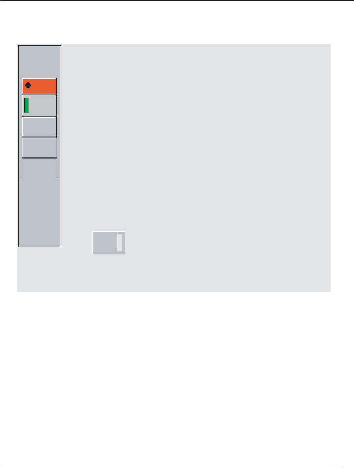
2.1.3Change Password
Change Password will allow the User to change the default password ‘manager’ to a new User password.
NOTE: |
Must be in the Setup Screen to change password. See section |
|
2.1.1 Enter Setup Screen for instructions. |
|
|
|
|
Proceed as follows: (Lower case and 20 characters maximum)
1.From the menu button click the Change Password button.
2.In the “New Password” text field type a new password. (up to 20 characters maximum, lower case) Refer to Figure 2-5. For instructions to use the keypad, see section 1.4 Keypad.
3.In the “Confirm Password” field enter the new password a second time to confirm the change, and press “Enter”. When the new password is changed a confirmation box will appear to verify password is saved.
Figure 2-5: Change Password Screen.
|
|
|
|
|
|
|
|
|
|
|
|
New Password |
|
|
|
||||
|
|
manager |
|
|
|
|
|
||
|
|
|
|
|
|
|
|
|
|
|
|
20 characters max. |
|
|
|
|
|
||
|
|
|
|
|
|
|
|
|
|
|
|
Confirm Password |
|
|
|
||||
|
|
manager |
|
|
|
|
|
||
|
|
|
|
|
|
|
|
|
|
|
|
|
|
|
|
|
|
|
|
|
Double tap on cursor to bring up keyboard |
|
|
||||||
|
|
|
|
|
|
|
|
|
|
|
|
Enter |
|
Password |
|
|
Once the |
||
|
|
|
Changed |
|
|
password is |
|||
|
|
|
|
|
|
|
changed this |
||
|
|
|
|
|
|
|
|
|
|
|
|
|
|
|
|
|
|
||
|
|
|
|
|
|
|
|
|
confirmation |
|
Back to Setup page |
|
|
|
|
|
|||
|
|
|
|
|
|
indicator is |
|||
|
|
|
|
|
|
|
|
|
displayed. |
|
|
|
|
|
|
|
|
||
|
|
|
|
|
|
|
|
|
|
|
|
|
|
|
|
|
|
|
|
|
|
|
|
|
|
|
|
|
|
To exit the screen without changes click “Back to Setup page” button.
GCC Setup |
page 2 — 5 |
 Loading...