


EPS 6000 UPS
Shared Systems
User’s Guide
IMPORTANT SAFETY INSTRUCTION
SAVE THESE INSTRUCTIONS — This manual contains important instructions for the EPS 6000 series UPS Systems that must be followed during installation, operation and maintenance of the equipment.
WARNING
O P E N I N G E N C L O S U R E S E X P O S E S VO LTAG E S . A LWAY S R E F E R QUALIFIED PERSONEL ONLY
H A Z A R D O U S S E RV I C E TO
WARNING
A s s t a n d a rd s , s p e c i f i c a t i o n s , a n d d e s i g n s a r e subject to chang e , please ask for confirmation of the information given in tihs publicaion .
T h i s m a n u a l s h o u l d n o t binder.
i s a c o n t ro l l e d d o c u m e n t , p a g e s i n d i v i d u a l ly b e r e m ov e d f ro m t h i s
NOTE
This equipment g enerates, uses, and can radiate r a d i o f r e q u e n cy e n e rg y a n d , i f n o t i n s t a l l e d a n d
used in |
accordance |
with instruction |
manual, may |
|
c a u s e |
h a r m f u l |
i n t e r f e r e n c e |
t o |
r a d i o |
communications . Operation of this equipment in a r e s i d e n t i a l a r e a i s l i k e l y t o c a u s e h a r m f u l interference in which case the user will be required to correct the interference at his own expense .

prepared for:
EPS 6000
Shared Systems
User’s Guide
For service call
1-800-438-7373
86-130034-00 B00 11/96
Copyright © 1996 MGE UPS Systems, Inc.. All rights reserved. Printed in U.S.A.
MGE UPS Systems
1660 Scenic Avenue Costa Mesa, CA 92626 (714) 557-1636

EPS 6000 UPS
Shared Systems
User’s Guide
Warranty
Seller warrants to the Ultimate Purchaser (the purchaser who buys for use, and not for resale) that all products furnished under this order and which are manufactured by Seller will conform to final specifications, drawings, samples and other written descriptions approved in writing by Seller, and will be free from defects in materials and workmanship. These warranties shall remain in effect for period of twelve (12) months after delivery to the Ultimate Purchaser. But if the Seller installs the equipment or supplies technical direction of installation by contract, said one year shall run from the completion of installation, provided installation is not unreasonably delayed by Ultimate Purchaser. Parts replaced or repaired in the warrant period shall carry the unexpired portion of the original warranty. A unit placed with the Purchaser on consignment and then later purchased will be warranted for twelve (12) months from the time the Seller receives notification of the Purchaser’s intent to purchase said consigned item. The foregoing in its entirety is subject to the provision that in no case will the total warranty period extend beyond 18 months from date Seller ships equipment from point of manufacture.
The liability of Seller hereunder is limited to replacing or repairing at Seller’s factory or on the job site at Seller’s option, any part or parts which have been returned to the Seller and which are defective or do not conform to such specifications, drawings or other written descriptions; provided that such part or parts are returned by the Ultimate Purchaser within ninety (90) days after such defect is discovered. The Seller shall have the sole right to determine if the parts are to be repaired at the job site or whether they are to be returned to the factory for repair or replacement. All items returned to Seller for repair or replacement must be sent freight prepaid to its factory. Purchaser must obtain Seller’s Return Goods Authorization prior to returning items. The above conditions must be met if warranty is to be valid. Seller will not be liable for any damage done by unauthorized repair work, unauthorized replacement parts, from any misapplication of the item, or for damage due to accident, abuse, or Act of God.
In no event shall the Seller be liable for loss, damage, or expense directly or indirectly arising from the use of the units, or from any other cause, except as expressly stated in this warranty. Seller makes no warranties, express or implied, including any warranty as to merchantability or fitness for a particular purpose or use. Seller is not liable for and Purchaser waives any right of action it has or may have against Seller for any consequential or special damages arising out of any breach of warranty, and for any damages Purchaser may claim for damage to any property or injury or death to any person arising out of its purchase of the use, operation or maintenance of the product. Seller will not be liable for any labor subcontracted or performed by Purchaser for preparation of warranted item for return to Seller’s factory or for preparation work for field repair or replacement. Invoicing of Seller for labor either performed or subcontracted by Purchaser will not be considered as a liability by the Seller.
This warranty shall be exclusive of any and all other warranties express or implied and may be modified only by a writing signed by an officer of the Seller. This warranty shall extend to the Ultimate Purchaser but to no one else. Accessories supplied by Seller, but manufactured by others, carry any warranty the manufacturers have made to Seller and which can be passed on to Ultimate Purchaser.
Seller makes no warranty with respect to whether the products sold hereunder infringe any patent, U.S. or foreign, and Buyer represents that any specially ordered products do not infringe any patent. Buyer agrees to indemnify and hold Seller harmless from any liability by virtue of any patent claims where Buyer has ordered a product conforming to Buyer’s specifications, or conforming to Buyer’s specific design.
Buyer has not relied and shall not rely on any oral representation regarding the Product sold hereunder and any oral representation shall not bind Seller and shall not be part of any warranty.
There are no warranties which extend beyond the description on the face hereof. In no event shall MGE UPS Systems, Inc. be responsible for consequential damages or for any damages except as expressly stated herein.
Service and Factory Repair - Call 1 - 800 - 438 - 7373
Direct questions about the operation, repair, or servicing of this equipment to MGE UPS Systems, Inc. Customer Support Services. Include the part number, assembly number, and serial number of the unit in any correspondence. Should you require factory service for your equipment, contact MGE UPS Systems, Inc. Customer Support Services and obtain a Return Goods Authorization (RGA) prior to shipping your unit. Never ship equipment to MGE UPS Systems, Inc. without first obtaining an RGA.
Proprietary Rights Statement
The information in this manual is the property of MGE UPS Systems, Inc., and represents a proprietary article in which MGE UPS Systems, Inc., retains any and all patent rights, including exclusive rights of use and/or manufacture and/or sale. Possession of this information does not convey any permission to reproduce, print, or manufacture the article or articles shown herein. Such permission may be granted only by specific written authorization, signed by an officer of MGE UPS Systems, Inc.
IBM, PC-AT, ES/9000, and AS/400 are trademarks of International Business Machines Corporation. MGE and MGE UPS Systems are trademarks of MGE UPS Systems, Inc. Other trademarks that may be used herein are owned by their respective companies and are referred to in an editorial fashion only.
Revision History
EPS 6000 Uninterruptible Power System Installation Manual 86-130034-00
Copyright © 1996 MGE UPS Systems. All rights reserved. Printed in U.S.A.
Revision: B00 |
11/96 |
|
|

Contents
Section I |
Introduction |
|
1.0 . . . . . . . . . . . . . . . |
Scope |
1 — 1 |
1.1 . . . . . . . . . . . . . . . |
General Description |
1 — 1 |
1.2 . . . . . . . . . . . . . . . |
Description of UPS Module |
|
|
Major Internal Components |
1 — 4 |
1.2.1 |
Rectifier/Battery Charger |
1 — 4 |
1.2.2 |
Inverter |
1 — 4 |
1.2.3 |
Inverter Transformer |
1 — 4 |
1.2.4 |
Battery System |
1 — 4 |
1.3 . . . . . . . . . . . . . . . |
Description of SSC |
|
|
Major Internal Components |
1 — 5 |
1.4 . . . . . . . . . . . . . . . |
Options |
1 — 13 |
1.5 . . . . . . . . . . . . . . . |
Specifications, UPS Modules |
1 — 13 |
1.5.1 |
Electrical |
1 — 13 |
1.5.2 |
Mechanical |
1 — 14 |
1.5.3 |
Environmental |
1 — 15 |
1.6 . . . . . . . . . . . . . . . |
Specifications, |
|
|
Static Switch Cabinet |
1 — 15 |
1.6.1 |
Electrical |
1 — 15 |
1.6.2 |
Mechanical |
1 — 16 |
1.6.2 |
Mechanical |
1 — 12 |
Section II |
Operation |
|
2.0 . . . . . . . . . . . . . . . |
Scope |
2 — 1 |
2.1 . . . . . . . . . . . . . . . |
System Operation Overview |
2 — 1 |
2.1.1 |
Static Switch Cabinet Operation |
2 — 1 |
2.1.2 |
Normal Operation |
2 — 2 |
2.1.3 |
On-Battery Operation |
2 — 2 |
2.2 . . . . . . . . . . . . . . . |
Indicators and Controls |
2 — 3 |
2.2.1 |
Front Panel |
2 — 3 |
2.2.2 |
Alphanumeric Display |
|
|
and Controls |
2 — 6 |
2.2.3 |
Hidden Panel |
2 — 9 |
2.2.4 |
Circuit Breakers, |
|
|
Contactors and Switches |
2 — 13 |
2.3 . . . . . . . . . . . . . . . |
Using the Alphanumeric Display |
2 — 23 |
2.3.1 |
Settings |
2 — 24 |
2.3.2 |
Alarms |
2 — 25 |
2.3.3 |
Measurements |
2 — 26 |
2.3.3.1 |
Voltage Measurements |
2 — 26 |
2.3.3.2 |
Current Measurements |
2 — 27 |
2.3.3.3 |
Power and |
|
|
Frequency Measurements |
2 — 28 |
2.3.3.4 |
Battery Measurements |
2 — 29 |
iii

EPS 6000 UPS Shared Systems
section |
description |
page number |
|
2.4 . . . . . . . . . . . . . . . Normal Operating Procedures |
2 — 29 |
||
2.4.1 |
Checks Before Start-up |
|
2 — 29 |
2.4.2 |
Start-up |
|
2 — 30 |
2.4.3 |
Checks After Start-up |
|
2 — 31 |
2.4.4 |
Shut-down |
|
2 — 32 |
2.4.4.1Emergency Shutdown
|
Using EPO |
2 — 32 |
2.4.4.2 |
Normal Shutdown |
2 — 33 |
2.4.5 |
Isolation for Maintenance |
2 — 33 |
2.4.5.1Isolation of an
|
Individual UPS Module |
2 — 33 |
2.4.5.2 |
Isolation of |
|
|
Static Switch Cabinet (SSC) |
2 — 35 |
2.4.5.2.1 |
Without Maintenance Bypass |
2 — 35 |
2.4.5.2.2 |
With Maintenance Bypass |
2 — 35 |
2.4.6 |
Forced Transfers |
2 — 36 |
2.4.6.1Uninterrupted
|
Transfer Conditions |
2 — 36 |
2.4.6.2 |
Forced Transfer From |
|
|
Bypass AC Input Source |
|
|
to Inverter |
2 — 37 |
2.4.6.3Forced UPS Module Shut Down 2 — 37
2.5 . . . . . . . . . . . . . . . LCD Messages 2 — 37
Section III |
Maintenance and Service |
|
3.0 . . . . . . . . . . . . . . . |
Scope |
3 — 1 |
3.1 . . . . . . . . . . . . . . . |
Safety Instructions |
3 — 1 |
3.2 . . . . . . . . . . . . . . . |
Preventive Maintenance |
3 — 1 |
3.3 . . . . . . . . . . . . . . . |
Replacement Parts |
3 — 2 |
3.4 . . . . . . . . . . . . . . . |
Troubleshooting and |
|
|
MGE Servicing |
3 — 3 |
Glossary . . . . . . . . . . . . . . . . . . . . . . . . . . . . . . . . . . . . . . . . . . g — 1
iv |
Contents |

User’s guide
Illustrations
figure |
description |
page number |
|
1-1 . . . . . . . . . . . . . . . |
Pictorial, Typical EPS 6000 UPS |
|
|
|
Shared Installation |
|
|
|
(Shown With Two 375 kVA |
|
|
|
UPS Modules) |
|
1 — 3 |
1-2 . . . . . . . . . . . . . . . |
Single-Line Diagram, |
|
|
|
Typical EPS 6000 UPS |
|
|
|
Shared Installation |
|
1 — 3 |
1-3 . . . . . . . . . . . . . . . |
EPS 6000 |
|
|
|
Major Internal Components, |
|
|
|
Shared 150 - 225 kVA |
|
|
|
UPS Modules |
|
1 — 5 |
1-4 . . . . . . . . . . . . . . . |
EPS 6000 |
|
|
|
Major Internal Components, |
|
|
|
Shared 375 kVA UPS Modules |
1 — 6 |
|
1-5 . . . . . . . . . . . . . . . |
EPS 6000 |
|
|
|
Major Internal Components, |
|
|
|
Shared 500 kVA UPS |
|
|
|
I/O Cabinet |
|
1 — 7 |
1-6 . . . . . . . . . . . . . . . |
EPS 6000 |
|
|
|
Major Internal Components, |
|
|
|
Shared 500 kVA UPS Cabinet |
1 — 8 |
|
1-7 . . . . . . . . . . . . . . . |
EPS 6000 |
|
|
|
Major Internal Components, |
|
|
|
Shared 750 kVA UPS Cabinet 1 |
1 — 9 |
|
1-8 . . . . . . . . . . . . . . . |
EPS 6000 |
|
|
|
Major Internal Components, |
|
|
|
Shared 750 kVA UPS Cabinet 2 |
1 — 10 |
|
1-9 . . . . . . . . . . . . . . . |
EPS 6000 |
|
|
|
Major Internal Components, |
|
|
|
Shared 750 kVA UPS |
|
|
|
Cabinet 3 |
|
1 — 11 |
1-10 . . . . . . . . . . . . . . |
EPS 6000 |
|
|
|
Major Internal Components, |
|
|
|
Static Switch Cabinet (SSC) |
|
1 — 12 |
2-1 . . . . . . . . . . . . . . . |
Power Flow, Normal Operation |
2 — 1 |
|
2-2 . . . . . . . . . . . . . . . |
Power Flow, |
|
|
|
On-Battery Operation |
|
2 — 2 |
2-3 . . . . . . . . . . . . . . . |
Power Flow, Bypass Operation |
2 — 3 |
|
2-4 . . . . . . . . . . . . . . . |
EPS 6000 |
|
|
|
Controls and Indicators |
|
2 — 4 |
2-5 . . . . . . . . . . . . . . . |
EPS 6000 Front Panel |
|
2 — 4 |
2-6 . . . . . . . . . . . . . . . |
Alphanumeric Display |
|
|
|
and Controls |
|
2 — 7 |
2-7 . . . . . . . . . . . . . . . |
Hidden Panel |
|
2 — 9 |
2-8 . . . . . . . . . . . . . . . |
Hidden Panel Pushbuttons |
|
2 — 12 |
Contents |
v |

EPS 6000 UPS Shared Systems
2-9 . . . . . . . . . . . . . . . |
Single-Line Diagram, |
|
|
Typical EPS 6000 UPS |
|
|
Shared Installation |
2 — 14 |
2-10 . . . . . . . . . . . . . . |
EPS 6000 |
|
|
Major Internal Components, |
|
|
Shared 150 - 225 kVA |
|
|
UPS Module |
2 — 15 |
2-11 . . . . . . . . . . . . . . |
EPS 6000 |
|
|
Major Internal Components, |
|
|
Shared 300 / 375 kVA |
|
|
UPS Module |
2 — 16 |
2-12 . . . . . . . . . . . . . . |
EPS 6000 |
|
|
Major Internal Components, |
|
|
Shared 500 kVA UPS Module |
|
|
I/O Cabinet |
2 — 17 |
2-13 . . . . . . . . . . . . . . |
EPS 6000 |
|
|
Major Internal Components, |
|
|
Shared 500 kVA UPS Module |
|
|
UPS Cabinet |
2 — 18 |
2-14 . . . . . . . . . . . . . . |
EPS 6000 |
|
|
Major Internal Components, |
|
|
Shared 750 kVA UPS Module |
|
|
UPS Cabinet 1 |
2 — 19 |
2-15 . . . . . . . . . . . . . . |
EPS 6000 |
|
|
Major Internal Components, |
|
|
Shared 750 kVA UPS Module |
|
|
UPS Cabinet 2 |
2 — 20 |
2-16 . . . . . . . . . . . . . . |
EPS 6000 |
|
|
Major Internal Components, |
|
|
Shared 750 kVA UPS Module |
|
|
UPS Cabinet 3 |
2 — 21 |
2-17 . . . . . . . . . . . . . . |
EPS 6000 |
|
|
Major Internal Components, |
|
|
Static Switch Cabinet (SSC) |
2 — 22 |
2-18 . . . . . . . . . . . . . . |
Alphanumeric Display |
2 — 23 |
2-19 . . . . . . . . . . . . . . |
General Display Configuration |
2 — 24 |
2-20 . . . . . . . . . . . . . . |
Display Settings Display |
2 — 24 |
2-21 . . . . . . . . . . . . . . |
Displaying Alarm Messages |
2 — 25 |
2-22 . . . . . . . . . . . . . . |
Voltage Measurements |
2 — 26 |
2-23 . . . . . . . . . . . . . . |
Current Measurements |
2 — 27 |
2-24 . . . . . . . . . . . . . . |
Power and |
|
|
Frequency Measurements |
2 — 28 |
2-25 . . . . . . . . . . . . . . |
Battery Measurements |
2 — 29 |
vi |
Contents |

User’s guide
Tables
table |
description |
page number |
|
1-1 . . . . . . . . . . . . . . . |
EPS 6000 Model Numbers, |
|
|
|
Shared System UPS Modules |
1 — 2 |
|
1-2 . . . . . . . . . . . . . . . |
EPS 6000 Model Numbers, |
|
|
|
Static Switch Cabinets (SSC) |
1 — 2 |
|
Contents |
vii |
EPS 6000 UPS Shared Systems
How to use this manual
This manual is designed for ease of use and easy location of information.
To quickly find the meaning of terms used within the text, look in the Glossary.
This manual uses Noteboxes to convey important information. Noteboxes come in four varieties:
WARNING
A WARNING notebox indicates infor mation provided to protect the user and ser vice personnel against safety hazards and/or possible equipment damage
CAUTION
A C AU T I O N n o t e b ox
i n d i c a t e s |
i n fo r m a t i o n |
||
provided |
to |
protect the |
|
u s e r |
a n d |
s e r v i c e |
|
p e r s o n n e l |
a g a i n s t |
||
p o s s i b l e |
|
e q u i p m e n t |
|
damage. |
|
|
|
IMPORTANT
An IMPORTANT notebox indicates infor mation provided as an operating instruction, or as an operating tip.
NOTE
A |
N O T E |
n o t e b o x |
|
i n d i c a t e s |
i n fo r m a t i o n |
||
p r o v i d e d |
a s |
a n |
|
o p e r a t i n g t i p o r a n equipment feature.
viii
Introduction
This manual provides technical information required for operation and maintenance of the shared EPS 6000
uninterruptible power system (UPS). Please read this manual before operating the EPS 6000 equipment. Please retain this manual for future reference.
The manual is divided into three sections:
Section I — General Description
This section introduces the EPS 6000 family of uninterruptible power systems, including a general description of the system and its internal components, a description of available options, and system specifications.
Section II — Operation
This section describes operating information for EPS 6000 UPS shared systems, including an overview of the system, its components, and their function; a description of the indicators and controls and their function; and operational sequences to be followed for all conditions of normal, emergency, and maintenance operation.
Section III — Maintenance and Service
This section describes maintenance of the EPS 6000 UPS, including safety instructions, preventive maintenance, information about replacement parts, and customer service.
A Glossary in the rear of this manual provides definitions of terms used within the text. A separate manual, EPS 6000 UPS Installation Manual (MGE part number 86-130035-00) provides detailed installation instructions.
1.1General Description EPS 6000 is a family of compact, high-efficiency uninter-
ruptible power systems, available in power ratings up to 1,500 kVA. EPS 6000 UPS are optimized for compatibility with non-linear computer-type loads. Computer-aided UPS diagnostics and modular construction assures that any required service on the UPS can be identified and completed rapidly. Remote system monitoring, remote annunciation of UPS performance signals, and telecommunication capabilities allow total control of the UPS by the user.
The EPS 6000 UPS, SSC, battery, and all auxiliary equipment is listed for safety by Underwriter’s Laboratories, Inc. (UL) under UL Standard 1778; and under Canadian Standards Association (CSA) standard C22.107.
Major components of the EPS 6000 UPS family include:
•EPS 6000 UPS module
•EPS 6000 SSC static switch cabinet
•EPS 6000 SSC maintenance bypass cabinet
•EPS 6000 auxiliary cabinet
1 — 1

EPS 6000 UPS Shared Systems
•EPS 6000 battery cabinet
Each of these cabinets is described below. Figure 1-1 shows a typical shared UPS installation, consisting of one static switch cabinet (SSC), two UPS modules, and two adjacent battery cabinets. Figure 1-2 shows a single-line diagram of the same
shared UPS installation. Table 1-1 identifies EPS 6000 UPS model numbers for modules used in shared systems, and Table 1-2 identifies EPS 6000 SSC model numbers.
Table |
|
E P S 6 0 0 0 M o d e l N u m b e rs , S h a r e d S y s t e m U P S M o d u l e s |
|
|
||||||
1-1 |
|
MODEL |
INPUT |
OUTPUT |
OUTPUT |
INPUT CB |
TOTAL WIDTH |
TOTAL |
HEAT |
|
|
VOLTAGE |
VOLTAGE |
RATING |
LOSS |
||||||
|
NUMBER |
(Amps) |
(mm/in) |
WEIGHT (kg/lb) |
||||||
|
|
(VAC) |
(VAC) |
(kVA/kW) |
(Btu/hr) |
|||||
|
|
|
|
|
|
|||||
|
|
|
|
|
|
|
|
|
|
|
|
|
EPS-6150/44,66P |
480 |
480 |
150/120 |
400 |
2,010/81.5 |
2,044/4,508 |
30,818 |
|
|
|
|
|
|
|
|
|
|
|
|
|
|
EPS-6225/44,66P |
480 |
480 |
225/180 |
400 |
2,010/81.5 |
2,044/4,508 |
39,202 |
|
|
|
|
|
|
|
|
|
|
|
|
|
|
EPS-6300/44,66P |
480 |
480 |
300/240 |
600 |
2,010/81.5 |
2,514/5,543 |
52,269 |
|
|
|
|
|
|
|
|
|
|
|
|
|
|
EPS-6375/44,66P |
480 |
480 |
375/300 |
700 |
2,010/81.5 |
2,545/5,612 |
65,336 |
|
|
|
|
|
|
|
|
|
|
|
|
|
|
EPS-6500/44,66P |
480 |
480 |
500/400 |
1000 |
2,865/113 |
4,244/7,211 |
79,453 |
|
|
|
|
|
|
|
|
|
|
|
|
|
|
EPS-6750/44,66P |
480 |
480 |
750/600 |
1600 |
4,900/195 |
6,000/13,200 |
131,000 |
|
|
|
|
|
|
|
|
|
|
|
|
NOTES:
Table 1-2
1.Total width, weight, and heat loss are for system line-up including auxiliary cabinets but excluding pallets.
2.Data does not include battery data; refer to the installation drawings supplied with your equipment.
3.Information provided is for standard configurations; data may change with optional equipment. Consult the installation drawings provided with your equipment.
E P S 6 0 0 0 M o d e l N u m b e rs , S t a t i c S w i t ch C a b i n e t s ( S S C )
MODEL |
INPUT |
OUTPUT |
OUTPUT |
INPUT CB |
TOTAL |
TOTAL |
HEAT |
|
VOLTAGE |
VOLTAGE |
RATING |
WIDTH |
WEIGHT |
LOSS |
|||
NUMBER |
(Amperes) |
|||||||
(VAC) |
(VAC) |
kVA/kW |
(mm/in) |
(kg/lb) |
(Btu/hr) |
|||
|
|
|||||||
|
|
|
|
|
|
|
|
SSC1500 |
480 |
480 |
1500/1200 |
2000 |
1829/72 |
1317/2900 |
(Negligible) |
|
|
|
|
|
|
|
|
1 — 2 |
Introduction |
User’s guide
Figure P i c t o r i a l , Ty p i c a l E P S 6 0 0 0 U P S S h a r e d I n s t a l l a t i o n
1-1 ( S h ow n W i t h Two 3 7 5 k VA U P S M o d u l e s )
MAINTENANCE BYPASS CABINET
(OPTIONAL)
STATIC SWITCH
CABINET (SSC)
BATTERY
CABINET
EPS 6000
AUXILIARY UPS MODULE
CABINET
Figure |
S i n g l e - L i n e D i ag r a m , Ty p i c a l E P S 6 0 0 0 U P S S h a r e d I n s t a l l a t i o n |
|||||||
1-2 |
MAINTENANCE |
|
|
|
|
|
|
|
BYPASS |
|
|
|
|
|
|
|
|
AC INPUT |
|
|
|
|
|
|
|
|
|
|
|
|
|
|
STATIC SWITCH |
MAINTENANCE |
|
|
|
|
|
|
|
CABINET |
BYPASS CABINET |
|
|
|
|
|
|
|
|
(OPTIONAL) |
|
|
|
|
|
|
|
STATIC SWITCH |
Q38P |
|
|
|
Q4S |
|
|
|
|
|
|
|
|
|
|
|
|
|
|
|
|
|
(CUSTOMER |
|
|
|
|
|
|
|
|
SUPPLIED) |
|
|
|
|
|
|
|
|
|
|
|
|
Q2S |
Q5N |
TO |
|
BYPASS |
|
|
|
|
|
|
|
|
|
|
|
|
|
|
ATTACHED |
|
|
AC INPUT/ |
|
|
|
|
|
|
|
|
|
|
|
|
|
|
LOAD |
|
|
MAINS 2 |
|
|
|
|
|
|
|
|
|
|
|
|
|
|
|
|
|
|
EPS 6000 UPS MODULE |
STATIC SWITCH |
|
|
|
|
|
|
|
|
|
|
|
|
|
|
|
|
Q1 |
|
INVERTER |
Q5N |
FROM ADDITIONAL |
|
|
|
MAIN |
|
K3N |
|
|
|||
|
|
UPS MODULES |
|
|
||||
|
|
|
|
|
|
|||
|
AC INPUT/ |
INPUT |
|
OUTPUT |
|
|
|
|
|
MAINS 1 |
|
|
|
|
|
||
|
FUSES |
|
FUSES |
|
|
|
|
|
|
|
RECTIFIER/ |
|
|
|
|
||
|
|
|
CHARGER |
|
|
|
|
|
|
|
|
EPS 6000 |
|
|
|
|
|
|
|
|
BATTERY |
QF1 |
|
|
|
|
|
|
|
CABINET |
|
|
|
|
|
|
|
EPS 6000 UPS MODULE |
STATIC SWITCH |
|
|
|
|
|
|
|
|
|
|
|
|
|
|
|
|
Q1 |
|
INVERTER |
Q5N |
|
|
|
|
|
|
K3N |
|
|
|
||
|
|
|
|
|
|
|
|
|
|
|
INPUT |
|
OUTPUT |
|
|
|
|
|
|
FUSES |
RECTIFIER/ |
FUSES |
|
|
|
|
|
|
|
CHARGER |
|
|
|
|
|
|
|
|
EPS 6000 |
|
|
|
|
|
|
|
|
BATTERY |
QF1 |
|
|
|
|
|
|
|
CABINET |
|
|
|
|
|
|
|
|
|
|
|
|
|
|
Introduction |
1 — 3 |

EPS 6000 UPS Shared Systems
1.2Description of UPS Following is a description of the EPS 6000 UPS major
Module Major
Internal
Components
internal components. Refer to the single-line diagram provided in Figure 1-2, and the component locators provided in Figure 1-3 through Figure 1-10
1.2.1Rectifier/Battery Charger
The rectifier/battery charger converts the AC input voltage from the utility source into a DC voltage, supplying the inverter and regulating the charge of the battery system. A capacitor bank filters the DC voltage.
1.2.2 |
Inverter |
The inverter chops the DC voltage supplied from either the |
|
|
rectifier/battery charger or the battery system into a three- |
|
phase AC voltage. An AC output filter is used to achieve a computer-grade sinewave output |
|
|
voltage waveform, with a total harmonic distortion of less than 2% under linear-load conditions. |
|
1.2.3 |
Inverter |
During normal operation, the inverter transformer provides |
|
Transformer |
complete electrical isolation between the UPS output to the |
|
attached load and the utility power source input as well as |
|
|
|
the UPS battery source. |
1.2.4 |
Battery System |
The battery system stores energy for use by the inverter. |
|
|
The stored energy is utilized in the event that the AC input |
|
power from the utility source fails, or falls outside of acceptable tolerance. |
|
The battery system may be an MGE battery cabinet designed for operation with the EPS 6000 UPS, or a customer-supplied battery installation.
MGE-supplied EPS 6000 battery cabinets may be a provided as stand-alone enclosures, or as enclosures designed to be mounted adjacent to the EPS 6000 UPS module.
The EPS 6000 comes with a special battery ambient temperature sensor which allows the optimization of the DC voltage level as a function of the temperature, ensuring that the battery is properly charged and preserving its longevity.
1 — 4 |
Introduction |
User’s guide
1.3Description of SSC The static switch cabinet (SSC) provides an electrical path
between the output of the UPS modules and the load. When the UPS modules are off, the SSC provides power to the load from the bypass AC input source (mains 2). Up to six (6) modules can be connected to the SSC, supporting loads as great as 1,500 kVA. UPS modules may be turned
off individually for maintenance, provided that the remaining modules can support the load.
The SSC incorporates a static bypass switch. A wrap-around circuit breaker (Q2S) in the SSC switches between the UPS module output and the bypass AC input source (when the UPS modules are off). Optionally, the SSC can be provided with its own maintenance bypass cabinet (MBC), allowing the SSC and/or any attached UPS module to be serviced while the load is supplied via the maintenance bypass AC input source.
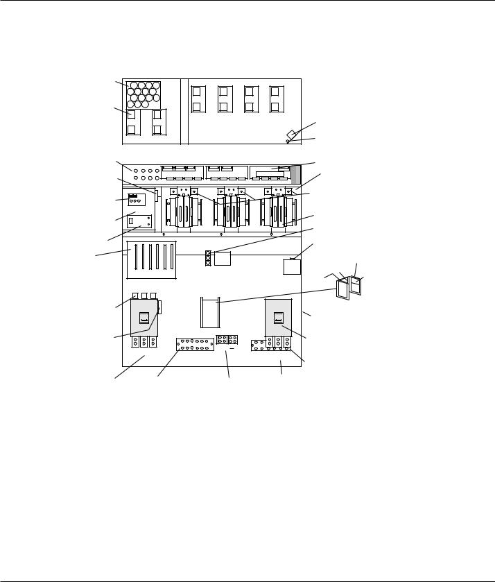
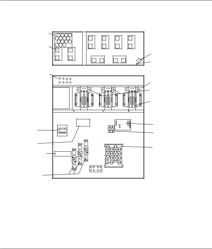
Figure E P S 6 0 0 0 M a j o r I n t e r n a l C o m p o n e n t s ,
1-3 S h a r e d 1 5 0 - 2 2 5 k VA U P S M o d u l e s
AC CAPACITOR |
|
|
|
|
ASSEMBLY |
|
|
|
|
|
3 |
4 |
5 |
6 |
FANS |
|
|
|
|
(x 6) |
|
|
|
|
1 |
2 |
|
|
FAN |
|
|
|
|
TRANSFORMER |
|
|
|
|
FB9 |
TOP VIEW, COVER REMOVED
FB1 TO FB8 |
|
|
|
FRONT VIEW, DOORS AND COVERS REMOVED |
IBEZ PCA |
||||
F10,F11 RATED 2A,500VDC |
FB1 |
FB2 |
FB3 FB4 |
|
RAUZ PCA |
OBEZ PCA |
DC CAPACITORS |
||
FB5 |
FB6 |
FB7 FB8 |
|
|
|
(BEHIND EACH INVERTER) |
|||
F12,F13 |
|
|
|
|
|
|
|
|
|
|
|
|
|
|
|
|
|
INVERTER FUSES (BEHIND) |
|
EPOZ |
|
|
|
|
|
|
|
|
|
CHARGER, STATIC SW, |
|
|
|
|
|
|
|
INVERTERS |
|
BAIZ & TREZ |
|
|
|
|
|
|
|
||
|
|
|
|
|
|
|
|
||
(BEHIND PLATE) |
|
|
|
|
|
|
|
|
|
ALBZ |
|
|
|
|
|
|
|
OUTPUT FUSES F7, F8, F9 |
|
|
|
|
|
|
|
|
|
||
|
|
|
|
|
|
|
|
120V AC OUTLET |
|
CARD CAGE: |
|
|
|
|
|
|
|
(FOR MGE USE ONLY) |
|
|
|
|
|
|
|
K3N |
ARUZ PCA (BEHIND MTG. PLATE) |
||
1- GTCZ PCA |
|
|
|
|
|
|
|||
|
|
|
|
|
|
|
|
||
2- SRIZ PCA |
1 |
2 |
3 |
4 |
5 |
6 |
|
ACPZ PCA |
|
3- CRIZ PCA |
|
K3NZ PCA |
|||||||
|
|
|
|
|
|
|
|||
4- CROZ / DO6Z PCA |
|
|
|
|
|
|
|
APOZ PCA |
|
5- AROZ PCA |
|
|
|
|
|
|
|
|
|
6- ALEZ PCA |
|
|
|
|
|
|
|
|
|
INPUT FUSES F1, F2, F3 |
|
Q1 |
|
|
|
|
Q5N |
||
|
|
|
|
|
|
|
|
OUTPUT XFMR |
|
|
|
|
|
|
|
|
|
(BEHIND BREAKERS) |
|
FUSES F16, F17 |
|
|
|
|
|
|
|
OUTPUT |
|
F18, F19 |
A3 B3 C3 |
|
|
+ |
CIRCUIT BREAKER |
||||
|
|
|
|||||||
|
|
|
A4 B4 C4 |
||||||
|
|
|
|
|
|
|
|
||
|
|
|
|
|
|
|
|
NEUTRAL CONNECTION |
|
|
|
|
|
|
|
|
|
(BEHIND OUTPUT) |
|
INPUT |
|
GROUND |
|
BATTERY |
OUTPUT |
||||
CONNECTIONS |
|
|
CONNECTIONS |
||||||
CONNECTIONS |
CONNECTIONS |
||||||||
|
|
||||||||
Introduction |
1 — 5 |
EPS 6000 UPS Shared Systems
Figure E P S 6 0 0 0 M a j o r
1-4 S h a r e d 3 7 5 k VA
I n t e r n a l C o m p o n e n t s , U P S M o d u l e s
AC CAPACITOR |
|
|
|
|
ASSEMBLY |
|
|
|
|
|
3 |
4 |
5 |
6 |
FANS |
|
|
|
|
(x 6) |
|
|
|
|
1 |
2 |
|
|
FAN |
|
|
|
|
TRANSFORMER |
|
|
|
|
FB9 |
TOP VIEW, COVER REMOVED
FB1 TO FB8 |
|
|
|
FRONT VIEW, DOORS AND COVERS REMOVED |
|
IBEZ PCA |
||||
F10,F11 RATED 2A,500VDC |
FB1 |
FB2 |
FB3 FB4 |
|
RAUZ PCA |
OBEZ PCA |
|
DC CAPACITORS |
||
FB5 |
FB6 |
FB7 FB8 |
|
|
|
|
(BEHIND EACH INVERTER) |
|||
F12,F13 |
|
|
|
|
|
|
|
|
|
|
|
|
|
|
|
|
|
|
|
INVERTER FUSES (BEHIND) |
|
EPOZ |
|
|
|
|
|
1 2 |
3 4 |
5 6 |
F23 TO F34 |
|
CHARGER, STATIC SW, |
|
|
|
|
|
|
|
|
INVERTERS (x6) |
|
BAIZ & TREZ |
|
|
|
|
|
|
|
|
||
|
|
|
|
|
|
|
|
|
||
(BEHIND PLATE) |
|
|
|
|
|
|
|
|
OUTPUT FUSES F7, F8, F9 |
|
|
|
|
|
|
|
|
|
|
||
ALBZ |
|
|
|
|
|
|
|
|
120V AC OUTLET |
|
|
|
|
|
|
|
|
|
|
||
CARD CAGE: |
|
|
|
|
|
|
|
|
(FOR MGE USE ONLY) |
|
|
|
|
|
|
|
K3N |
|
ARUZ PCA (BEHIND MTG. PLATE) |
||
1- GTCZ PCA |
|
|
|
|
|
|
|
|||
|
|
|
|
|
|
|
|
|
||
2- SRIZ PCA |
1 |
2 |
3 |
4 |
5 |
6 |
|
|
ACPZ PCA |
|
3- CRIZ PCA |
|
|
K3NZ PCA |
|||||||
|
|
|
|
|
|
|
|
|||
4- CROZ / DO6Z PCA |
|
|
|
|
|
|
|
|
APOZ PCA |
|
5- AROZ PCA |
|
|
|
|
|
|
|
|
|
|
6- ALEZ PCA |
|
|
|
|
|
|
|
|
|
|
INPUT FUSES F1, F2, F3 |
|
Q1 |
|
|
|
|
Q5N |
|
||
|
|
|
|
|
|
|
|
|
OUTPUT XFMR |
|
|
|
|
|
|
|
|
|
|
(BEHIND BREAKERS) |
|
FUSES F16, F17 |
|
|
|
|
|
|
|
|
OUTPUT |
|
F18, F19 |
A3 B3 C3 |
|
|
+ |
|
CIRCUIT BREAKER |
||||
|
|
|
|
|||||||
|
|
|
A4 B4 C4 |
|
||||||
|
|
|
|
|
|
|
|
NEUTRAL CONNECTION |
||
|
|
|
|
|
|
|
|
|
||
|
|
|
|
|
|
|
|
|
(BEHIND OUTPUT) |
|
INPUT |
|
GROUND |
|
BATTERY |
OUTPUT |
|
||||
CONNECTIONS |
|
|
CONNECTIONS |
|||||||
CONNECTIONS |
CONNECTIONS |
|||||||||
|
|
|
||||||||
1 — 6 |
Introduction |
User’s guide
Figure E P S 6 0 0 0 M a j o r I n t e r n a l C o m p o n e n t s ,
1-5 S h a r e d 5 0 0 k VA U P S I / O C a b i n e t
NEUTRAL CONNECTION |
GROUND CONNECTION |
|
TOP VIEW, COVERS REMOVED
NEUTRAL
FRONT VIEW, DOORS AND COVERS REMOVED
CONNECTION
|
|
INPUT |
OUTPUT |
|
BATTERY |
BONDING |
||
GROUND |
CONNECTIONS |
CONNECTIONS |
CONNECTIONS |
|||||
A3 B3 |
C3 |
A4 B4 |
C4 |
|
|
JUMPER |
||
CONNECTION |
|
|
|
|
|
|
|
|
|
|
|
|
|
|
|
|
SHUNT |
|
|
Q1 |
|
|
Q5N |
|
|
L2 |
|
|
|
|
|
|
|
|
CURRENT XFMRS |
INPUT FUSES |
|
|
|
|
A12 B12 C12 |
|
|
|
F1,F2,F3 |
A1 |
B1 |
C1 |
|
|
|
|
|
|
|
|
|
|
|
|
N12 |
ACPZ |
|
|
|
|
|
|
|
|
|
FUSES F16,F17 |
|
|
|
|
|
|
|
|
|
|
|
|
|
|
A2 |
C2 |
ARUZ |
|
|
|
|
|
|
|
B2 |
|
|
|
|
|
|
|
|
|
|
|
|
|
|
|
|
|
|
L4 |
L3 |
|
|
|
|
|
|
|
|
AC CAPACITORS
Introduction |
1 — 7 |

EPS 6000 UPS Shared Systems
Figure E P S 6 0 0 0 M a j o r I n t e r n a l C o m p o n e n t s ,
1-6 S h a r e d 5 0 0 k VA U P S C a b i n e t
AC CAPACITOR |
|
|
|
|
|
ASSEMBLY |
|
3 |
4 |
5 |
6 |
|
|
||||
FANS |
|
|
|
|
FAN |
1 |
2 |
|
|
TRANSFORMER |
|
(x 8) |
7 |
|
8 |
||
|
|
|
|||
|
|
|
|
TOP VIEW, COVER REMOVED
IBEZ
FB1 TO FB8 |
FRONT VIEW, DOORS AND COVERS REMOVED |
EPOZ |
|
|
|
|
|
|
|
|
|
OBEZ |
CHARGER & TREZ |
|
|
|
|
|
1 2 |
3 4 |
5 |
6 |
RAUZ |
|
|
|
|
|
|
|
|
|
|
|
(BEHIND PLATE) |
|
|
|
|
|
|
|
|
|
DC CAPACITERS |
|
|
|
|
|
|
|
|
|
|
(BEHIND EACH INVERTER) |
|
|
|
|
|
|
|
|
|
|
INVERTERS (x6) |
AC OUTPUT |
|
|
|
|
|
|
|
|
|
APOZ |
CAPACITORS |
|
|
|
|
|
|
|
|
|
|
|
|
|
|
|
|
|
|
|
|
|
CARD CAGE: |
|
|
|
|
|
|
|
|
|
ALBZ |
1- GTCZ PCA |
|
|
|
|
|
|
|
|
|
|
|
|
|
|
|
|
|
|
|
F10,F11,F18,F19 |
|
2- SRIZ PCA |
|
|
|
|
|
|
|
|
|
|
3- CRIZ PCA |
1 |
2 |
3 |
4 |
5 |
6 |
|
|
|
|
4- CROZ / DO6Z PCA |
|
|
|
|
|
|
|
|
|
F12,F13 |
5- AROZ PCA |
|
|
|
|
|
|
|
|
|
|
|
|
|
|
|
|
|
|
|
DELAY |
|
6- ALEZ PCA |
|
|
|
|
|
|
|
|
|
|
|
|
|
|
|
|
|
|
|
|
|
K3NZ |
|
|
|
|
|
|
|
|
|
|
K3N |
|
|
|
|
|
|
|
|
|
BATTERY |
|
|
|
|
|
|
|
|
|
|
CONNECTION |
STATIC SWITCH |
|
|
|
|
|
|
|
|
|
(OPTIONAL) |
OUTPUT FUSES |
|
|
|
|
|
|
NEUTRAL |
|
|
AC CAP ASSY. |
|
|
|
|
|
|
|
|
|
||
F7, F8, F9 |
|
|
|
|
|
|
|
|
|
K1 |
|
|
|
|
|
|
|
|
|
|
1 — 8 |
Introduction |
User’s guide
Figure E P S 6 0 0 0 M a j o r I n t e r n a l C o m p o n e n t s ,
1-7 S h a r e d 7 5 0 k VA U P S C a b i n e t 1
Neutral |
|
Ground |
|
|
Connection |
Choke |
Connection |
|
|
Resistors |
|
|
|
|
Capacitors |
|
|
|
|
|
|
|
( - ) |
|
|
|
|
( + ) |
|
|
|
|
Bonding |
|
|
Top view |
|
jumper |
|
|
|
|
|
|
Ground |
|
|
|
|
Connection |
|
|
|
|
Input |
Output |
|
|
|
Connections |
|
|
|
|
Connections |
Battery |
|
|
|
|
|
|
||
|
|
|
|
|
|
|
Connections |
|
|
A3 B3 C3 |
A4 B4 C4 |
(+) (-) |
Relay |
Shunt |
|
|
|
|
|
|
|
|
Fuses |
|
|
Q5N |
|
|
|
Q1 |
(optional) |
|
|
|
CT (4ea)
Input fuses |
|
|
|
F1, F2, F3 |
|
|
|
|
ARUZ |
|
|
|
ACPZ |
|
|
Power |
|
|
Induction Filter |
CT (6ea) |
|
(2 ea) one on |
|
Interconnect |
|
other side |
|
|
|
||
Input Filter |
|
|
AC capacitors |
|
|
(2ea) one on |
|
Capacitors |
|
|
|
|
|
other side |
|
|
|
|
|
|
|
BAIZ |
Induction filter |
|
|
|
|
|
|
|
(2ea) one on |
|
|
|
other side |
Static Switch |
|
|
Cooling fans |
|
|
|
(2ea) |
Front view, doors, cover and some components removed for clarity. |
|
|
Side View |
Introduction |
1 — 9 |
EPS 6000 UPS Shared Systems
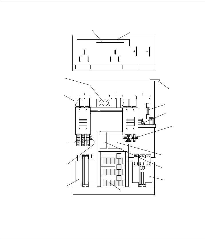
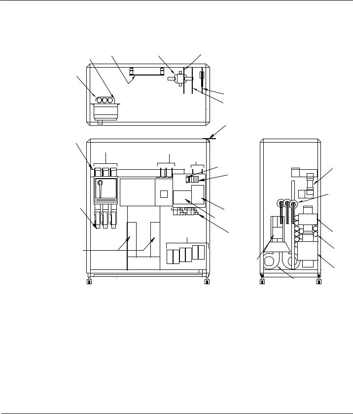
Figure E P S 6 0 0 0 M a j o r I n t e r n a l C o m p o n e n t s ,
1-8 S h a r e d 7 5 0 k VA U P S C a b i n e t 2
AC CAPACITOR |
|
|
|
|
ASSEMBLY |
|
|
|
|
|
3 |
4 |
5 |
6 |
FANS |
|
|
|
|
(x 8) |
|
|
|
FAN |
1 |
2 |
|
|
|
|
|
7 |
8 |
TRANSFORMER |
|
|
FB9 |
||
|
|
|
|
|
|
TOP VIEW, COVER REMOVED |
|
|
|
FB1 TO FB8 |
|
FRONT VIEW, DOORS AND COVERS REMOVED |
|
|
|
|
|
|
|
|
DC CAPACITORS |
FB1 |
FB2 |
FB3 FB4 |
|
|
(BEHIND EACH INVERTER) |
|
|
|
|
|
|
FB5 |
FB6 |
FB7 FB8 |
|
|
|
|
|
|
|
|
INVERTER FUSES (BEHIND) |
|
|
1 2 |
3 4 |
5 6 |
F24,F26,F28,F30,F32,F34 |
|
|
|
|
|
INVERTERS (x6) |
|
|
|
|
|
ALBZ |
K3N |
|
|
|
|
F10,F11 |
|
|
|
|
|
|
K3NZ |
|
|
|
|
AC OUTPUT |
|
|
|
|
|
|
|
|
|
|
|
CAPACITORS |
STATIC SWITCH |
|
|
|
|
|
OUTPUT FUSES |
|
|
NEUTRAL |
|
|
1 — 10 |
Introduction |
User’s guide
F i g u r e E P S 6 0 0 0 M a j o r I n t e r n a l C o m p o n e n t s ,
1-9 S h a r e d 7 5 0 k VA U P S C a b i n e t 3
AC CAPACITOR |
|
|
|
|
ASSEMBLY |
|
|
|
|
|
3 |
4 |
5 |
6 |
FANS |
|
|
|
|
(x 8) |
|
|
|
|
1 |
2 |
|
|
FAN |
|
|
|
|
TRANSFORMER |
|
|
|
|
FB9 |
TOP VIEW, COVER REMOVED
FB1 TO FB8 |
|
|
FRONT VIEW, DOORS AND COVERS REMOVED |
|
IBEZ PCA |
||
|
FB1 |
FB2 |
FB3 FB4 |
RAUZ PCA |
OBEZ PCA |
|
DC CAPACITORS |
|
|
|
|
|
|||
|
FB5 |
FB6 |
FB7 FB8 |
|
|
|
(BEHIND EACH INVERTER) |
|
|
|
|
|
|
|
INVERTER FUSES (BEHIND) |
EPOZ |
|
|
|
1 2 |
3 4 |
5 6 |
F24,F26,F28,F30,F32,F34 |
|
|
|
|
|
|
|
INVERTERS (x6) |
CARD CAGE: |
|
|
|
|
|
|
DOUZ |
|
|
|
|
|
|
|
|
1- GTCZ PCA |
|
|
|
|
|
|
|
2- SRIZ PCA |
|
|
|
|
|
|
ALBZ |
3- CRIZ PCA |
|
|
|
|
|
|
|
|
|
|
|
|
|
|
|
4- CROZ / DO6Z PCA |
|
|
|
|
|
|
|
5- AROZ PCA |
1 2 3 4 |
5 6 |
|
|
F10,F11 |
||
6- ALEZ PCA |
|
|
|
|
|
|
ACOZ |
|
|
|
|
|
|
|
|
POWER |
|
|
|
|
|
|
|
INTERCONNECT |
|
|
|
|
|
|
|
|
|
|
|
|
|
|
AC OUTPUT |
|
|
|
|
|
|
|
CAPACITOR ASSY |
OUTPUT FUSES |
|
|
|
|
|
|
|
Introduction |
1 — 11 |
EPS 6000 UPS Shared Systems
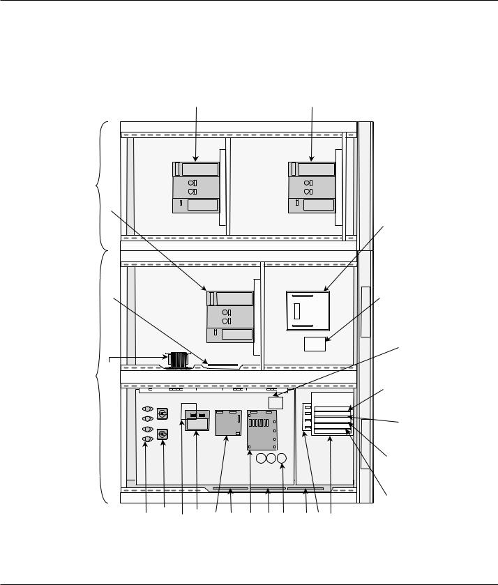
Figure |
E P S 6 0 0 0 M a j o r I n t e r n a l C o m p o n e n t s , |
|
1-10 |
S t a t i c S w i t ch C a b i n e t ( S S C ) |
|
|
CIRCUIT BREAKER (Q3BP) |
CIRCUIT BREAKER (Q5N) |
MAINTENANCE BYPASS CABINET |
(WITH FRONT DOOR REMOVED) |
CIRCUIT BREAKER (Q2S) |
|
|
PCA (CBOZ) |
STATIC SWITCH CABINET |
(WITH FRONT DOORS REMOVED) |
TRANSFORMER (T12) |
BYPASS
UPS
BYPASS
UPS
FUSES (F1, F2, F3, & F4) |
ROTARY SWITCHES (SW1, & SW2) |
TRANSFORMER (T13) FAR SIDE OF PANEL |
PCA (EPOZ) |
PCA (ACOZ) |
PCA (RAUZ) |
PCA (ACPZ) |
PCA (OBEZ) |
CAPACITORS (C11, C12, & C13) FAR SIDE OF PANEL |
PCA (IBEZ) |
PCA (PROZ) |
CARD CAGE |
STATIC SWITCH |
|
STATIC SWITCH PCA (SSSZ) |
|
(GTCZ) |
FUSES (F11, F12, & F13) FAR SIDE OF PANEL |
PCA |
|
|
PCA (SRIZ) |
PCA (AROZ) |
|
PCA (ALEZ) |
|
1 — 12 |
Introduction |

User’s guide
This section describes options available for the EPS 6000 UPS. Some configurations do not support some options.
Most options must be specified at the time of equipment order; some options can be installed in the field. Contact your MGE dealer for complete information.
Additional battery cabinets
Up to a maximum of four battery cabinets can be supplied for a single EPS 6000 UPS module, making additional back-up time available during power outages.
Input filter
An input harmonic current filter is available for the EPS 6000 UPS. For some power levels, the input filter is installed within the UPS enclosure. For others, the input filter is installed in an auxiliary cabinet.
High interrupting capacity circuit breakers
The EPS 6000 UPS module is normally equipped with circuit breakers rated at 30 kAIC. As an option, these breakers can be provided with a rating of 65 kAIC.
Maintenance bypass
For the UPS modules, maintenance bypass is provided by the SSC, allowing any or all attached UPS modules to be taken off-line while the SSC supports the attached load from its bypass source. As an option, the SSC can be equipped with its own maintenance bypass, allowing the SSC as well as any/all attached UPS modules to be serviced while the load is supported by the maintenance bypass AC input source.
Active RS-232/RS-485
A communications port is available that allows the UPS module or the SSC to be monitored from a remote terminal or computer. For detailed information on the communication features, contact your MGE dealer.
1.5Specifications, UPS Modules
1.5.1Electrical
Specifications provided refer to an EPS 6000 UPS module and any required auxiliary cabinets.
AC input ratings |
|
|
|
|
|
|
|
|
Voltage: |
208 or 480 VAC, +10%, -15% |
|
|
|
|
|||
Frequency: |
60 Hz, ± 10% |
|
|
|
|
|
||
Phases: |
3 Ø (phase sequence must be A, B, C) |
|
|
|
||||
Wires: |
3 or 4 wires plus ground |
|
|
|
|
|||
Current: |
|
|
|
|
|
|
|
|
|
rating in kVA |
150 |
225 |
300 |
375 |
500 |
750 |
|
|
|
|
|
|
|
|
|
|
|
Amperes @ 480 VAC |
200 |
300 |
400 |
490 |
702 |
980 |
|
|
|
|
|
|||||
Power factor: |
Up to 0.9 lagging; 0.95 with optional input harmonic filter |
|||||||
Introduction |
1 — 13 |

EPS 6000 UPS Shared Systems
AC output ratings |
|
|
|
|
|
|
|
Voltage: |
480 VAC ± 0.5% (steady-state conditions) |
|
|||||
|
|
480 VAC ± 5% (transient conditions |
|
|
|||
|
|
from 0% to 100% or 100% to 0%) |
|
|
|||
Frequency: |
60 Hz ± 0.1% (free-running) |
|
|
|
|||
Phases: |
3 Ø (phase sequence must be A, B, C) |
|
|||||
Wires: |
4 wires plus ground |
|
|
|
|
||
Current: |
|
|
|
|
|
|
|
|
rating in kVA |
150 |
225 |
300 |
375 |
500 |
750 |
|
|
|
|
|
|
|
|
|
Amperes @ 480 VAC |
180 |
271 |
361 |
451 |
601 |
902 |
|
|
|
|
|
|
|
|
Power factor: |
0.8 lagging |
|
|
|
|
||
Total harmonic distortion |
|
|
|
|
|
|
|
(THD): |
< 2% (linear load) |
|
|
|
|
||
|
|
< 4% (for 100% non-linear load |
|
|
|||
|
|
with a crest factor of up to 3.5) |
|
|
|||
Dynamic regulation: |
± 0.5% for balanced load |
|
|
|
|||
|
|
± 2.5% for 100% unbalanced load |
|
|
|||
Dynamic response: |
± 5% for 100% step load change |
|
|
||||
Overload: |
125% of rated load for 10 minutes |
|
|
||||
|
|
150% of rated load for 1 minute |
|
|
|||
DC ratings |
|
|
|
|
|
|
|
Battery voltage: |
545 Vdc float |
|
|
|
|
||
|
|
480 Vdc nominal |
|
|
|
|
|
|
|
390 Vdc minimum |
|
|
|
|
|
|
rating in kVA |
150 |
225 |
300 |
375 |
500 |
750 |
|
|
|
|
|
|
|
|
|
Maximum battery current |
323 |
485 |
647 |
809 |
1,074 |
1,620 |
|
at cut-off voltage (ADC) |
||||||
|
|
|
|
|
|
|
|
|
|
|
|
|
|
|
|
1.5.2Mechanical
Height: |
1,905 mm (75”) |
Depth: |
815 mm (32”) |
Width: |
See Table 1-1 |
Weight: |
See Table 1-1 |
Finish: |
MGE light gray |
1 — 14 |
Introduction |

User’s guide
1.5.3Environmental
Recommended environment: 20° to 25° C (68° to 77° F.); 50% relative humidity;
|
computer room or other temperatureand humidity- |
|||||
|
controlled environment |
|
|
|
||
Operating temperature: |
0° to 40° C (32° to 104° F.) except battery |
|
||||
Storage: |
-20° to 50° C (-4° to 122° F.) |
|
|
|
||
Humidity: |
up to 90% non-condensing (operating) |
|
|
|||
Altitude: |
sea level to 1,000 meters (sea level to 3,280 feet) |
|||||
|
without derating; 1,000 to 2,000 meters (3,280 |
|
||||
|
to 6,560 feet): derate operating temperature to a |
|||||
|
maximum of 28° C (82° F) |
|
|
|
||
Acoustic noise: |
|
|
|
|
|
|
rating in kVA |
150 |
225 |
300 |
375 |
500 |
750 |
|
|
|
|
|
|
|
Accoustic noise at rated |
|
|
|
|
|
|
load in dBA at 5 feet |
|
|
|
|
|
|
from the front of |
|
|
|
|
|
|
the UPS module |
72 |
72 |
72 |
72 |
75 |
78 |
|
|
|
|
|
|
|
1.6Specifications, Static Switch Cabinet
1.6.1 Electrical
AC input ratings |
|
Voltage: |
480 VAC, ± 15% |
Frequency: |
60 Hz, ± 10% |
Phases: |
3 Ø (phase sequence must be A, B, C) |
Wires: |
3 or 4 wires plus ground |
Current: |
2,000 Amperes |
AC output ratings |
|
Voltage: |
480 VAC |
Frequency: |
60 Hz |
Phases: |
3 Ø |
Wires: |
4 wires plus ground |
Current: |
2,000 Amperes |
Power factor: |
0.8 lagging |
Introduction |
1 — 15 |

EPS 6000 UPS Shared Systems
1.6.2Mechanical
Height: |
1,981 mm/78 in. |
Depth: |
1,219 mm/48 in. |
Width: |
1,829 mm/72 in. |
Weight: |
1,310 kg/2,900 lbs. (SSC) |
|
1,091 kg/2,000 lbs. (MBC) |
Finish: |
MGE light gray |
1 — 16 |
Introduction |
 Loading...