


w w w . m g e u p s . c o m
Pulsar MX
5000 RT — UPS
EXB RT — Extended Battery
Transformer 5000
Installation and User Manual

Installation and User Manual
Pulsar MX
Installation and User Manual
Revision History
Pulsar MX Installation and User Manual, 86-87050-00
Revision: A00 |
ECN#: |
004747 |
04/2006 |
Revision: A01 |
ECN#: |
004773 |
05/2006 |
Copyright © 2006 MGE UPS SYSTEMS, INC.
All rights reserved. Printed in U.S.A.
MGE UPS SYSTEMS, INC. 1660 Scenic Avenue Costa Mesa, CA 92626 (714) 557-1636
Technical Support:
1-800-523-0142 (during business hours)
Customer Care Center: 1-800-438-7373 (Hours: 24/7)
86-87050-00 A01

Pulsar MX
86-87050-00 A01

Contents
Introduction .......................................................................................................................... |
1 |
Important Safety Instructions .............................................................................................................. |
2 |
Symbol Usage .......................................................................................................................... |
3 |
Presentation
1.1 |
Standard Positions.......................................................................................................... |
1 — 1 |
1.2 |
Rear Panels .................................................................................................................. |
1 — 2 |
1.3 |
Display and Control Panel ............................................................................................ |
1 — 3 |
1.4 |
Accessories for Rack Mount .......................................................................................... |
1 — 3 |
1.5 |
Extended Battery (EXB) ................................................................................................ |
1 — 4 |
Installation
2.1 |
Unpacking and Contents Check .................................................................................... |
2 — 1 |
2.2 |
Internal Batteries Connection (Battery Start-Up)............................................................ |
2 — 2 |
2.3 |
Installation in Tower Position ........................................................................................ |
2 — 2 |
2.4 |
Installation in Rack Position............................................................................................ |
2 — 3 |
2.5 |
Communication Ports .................................................................................................... |
2 — 5 |
2.6 |
Required Protective Devices and Cable Cross-Sections .............................................. |
2 — 6 |
2.7 |
Hardwire Connection of Output Power Cable to UPS.................................................... |
2 — 7 |
2.8 |
Connection to Output Receptacles ................................................................................ |
2 — 8 |
2.9 |
Connection of Extended Battery Module, UPS, and Transformer ................................ |
2 — 8 |
Operation |
|
|
3.1 |
Initial Start-Up ................................................................................................................ |
3 — 1 |
3.2 |
Final Start-Up Sequence ................................................................................................ |
3 — 1 |
3.3 |
Operating Modes .......................................................................................................... |
3 — 2 |
3.4 |
Operation on Battery Power .......................................................................................... |
3 — 3 |
3.5 |
Return to Normal AC Source. ........................................................................................ |
3 — 4 |
3.6 |
UPS Shutdown When AC Present ................................................................................ |
3 — 4 |
3.7 |
UPS Shutdown When on Battery .................................................................................. |
3 — 4 |
Access to Maintenance and Personalization Data
4.1 |
Display Organization ...................................................................................................... |
4 — 1 |
4.2 |
Access to Measurements. .............................................................................................. |
4 — 1 |
4.3 |
Access to UPS Set-Up and Maintenance Using the Control Panel .............................. |
4 — 1 |
4.4 |
UPS Set-Up .................................................................................................................. |
4 — 2 |
4.5 |
Maintenance .................................................................................................................. |
4 — 3 |
4.6 |
Personalization Using External Software ...................................................................... |
4 — 3 |
Troubleshooting
5.1 |
Troubleshooting LEDS (21) and (22).............................................................................. |
5 — 1 |
5.2 |
Troubleshooting Not Requiring MGE UPS SYSTEMS .................................................. |
5 — 2 |
5.3 |
Troubleshooting Requiring MGE UPS SYSTEMS After-Sales Support ........................ |
5 — 3 |
86-87050-00 A01 |
Contents |
c i |

Pulsar MX
Life Cycle Monitoring (LCM)
6.1 |
Description .................................................................................................................. |
6 — 1 |
Maintenance
7.1 |
Hot Swapping the Power Sub-Module ........................................................................... |
7 — 1 |
7.2 |
Hot Swapping the Battery Sub-Module ......................................................................... |
7 — 2 |
Appendices
Technical Specifications............................................................................................................... |
8 — 1 |
MGE Warranty & Proprietary Rights for Single Phase Products
MGE Standard Single Phase Warranty
Proprietary Rights Statement
Customer Care Center - Single Phase Products
Technical Support and Product Services
Who to Contact
Scheduling Field Service Engineer Support
Return Policy for Repair of Single Phase Products (RGA)
Glossary
c ii |
Contents |
86-87050-00 A01 |
Introduction
Thank you for selecting an MGE UPS SYSTEMS product to protect your electrical equipment.
The Pulsar MX range has been designed with the utmost care.
We recommend that you take the time to read this manual to take full advantage of the many features of your UPS (Uninterruptible Power System).
Warning: This is a class A UPS product. In a domestic environment, this product may cause radio interference, in which case, the user may be required to take additional measures.
If the device must be installed in overvoltage category III or IV environments, additional upstream overvoltage protection must be provided for.
Before installing Pulsar MX, please read the booklet on the required safety instructions. Then follow the indications in this manual.
To discover the entire range of MGE UPS SYSTEMS products and the options available for the Pulsar MX range, we invite you to visit our web site at www.mgeups.com or contact your MGE UPS SYSTEMS representative.
Environmental protection
MGE UPS SYSTEMS has implemented an environmental-protection policy.
Products are developed according to an eco-design approach.
Substances
This product does not contain CFCs, HCFCs or asbestos.
Packing
To improve waste treatment and facilitate recycling, separate the various packing components.
The cardboard we use comprises over 50% of recycled cardboard.
Sacks and bags are made of polyethylene.
Packing materials are recyclable and bear the appropriate identification symbol. |
01 |
|
||
|
|
PET |
|
|
Material |
Abbreviation |
Symbol |
01 |
|
number PET |
||||
|
|
|||
Polyethylene terephthalate |
PET |
01 |
|
|
|
|
|
|
|
High-density polyethylene |
HDPE |
02 |
|
|
|
|
|
|
|
Polyvinyl chloride |
PVC |
03 |
|
|
|
|
|
|
|
Low-density polyethylene |
LDPE |
04 |
|
|
|
|
|
|
|
Polypropylene |
PP |
05 |
|
|
|
|
|
|
|
Polystyrene |
PS |
06 |
|
|
|
|
|
|
|
Follow all local regulations for the disposal of packing materials.
End of life
MGE UPS SYSTEMS will process products at the end of their service life in compliance with local regulations.
MGE UPS SYSTEMS works with companies in charge of collecting and eliminating our products at the end of their service life.
Product
The product is made up of recyclable materials.
Dismantling and destruction must take place in compliance with all local regulations concerning waste.
At the end of its service life, the product must be transported to a processing centre for electrical and electronic waste.
Battery
The product contains lead-acid batteries that must be processed according to applicable local regulations concerning batteries.
The battery may be removed to comply with regulations and in view of correct disposal. The "Material Safety Data Sheets" (MSDS) for the batteries are available on our web site*.
(*) For more information or to contact the Product Environmental manager, use the "Environmental Form" on the site: www.mgeups.com -> About us -> Environment.
86-87050-00 A01 |
Introduction |
1 |

Pulsar MX
IMPORTANT SAFETY INSTRUCTIONS
SAVE THESE INSTRUCTIONS. This manual contains important instructions that should be followed during installation and maintenance of the UPS and batteries.
The Pulsar MX models that are covered in this manual are intended for installation in an environment within 0 to 40° C, free of conductive contaminant.
This equipment has been tested and found to comply with the limits for a Class A digital device, pursuant to Part 15 of the FCC Rules. These limits are designed to provide reasonable protection against harmful interference when the equipment is operated in a commercial environment. This equipment generates, uses, and can radiate radio frequency energy and, if not installed and used in accordance with the instruction manual, may cause harmful interference to radio communications. Operation of this equipment in a residential area is likely to cause harmful interference in which case the user will be required to correct the interference at his own expense.
Certification Standards
IEEE 587-1980/ANSI C62.41 1980 Standards for Surge Withstand Ability
FCC rules and regulations of Part 15, Subpart J, Class A
UL listed under 1778, Standards for Uninterruptible Power Supply Equipment
IEC 61000-4-2 (ESD): level 4
IEC 61000-4-3 (Radiated field): level 3
IEC 61000-4-4 (EFT): level 4
IEC 61000-4-5 (Fast transients): level 4
IEEE-C6241 Category B (ring wave)
IEC 61000-4-6 (electromagnetic field)
IEC 61000-4-8 (conducted magnetic field)
Safety of persons
The system has its own power source (the battery). Consequently, the power outlets may be energized even if the systems is disconnected from the AC power source.
Dangerous voltage levels are present within the system. It should be opened exclusively by qualified service personnel.
The system must be properly grounded.
The battery supplied with the system contains small amounts of toxic materials. To avoid accidents, the directives listed below must be observed:
-Never burn the battery (risk of explosion).
-Do not attempt to open the battery (the electrolyte is dangerous for the eyes and skin).
-Comply with all applicable regulations for the disposal of the battery.
-Batteries constitute a danger (electrical shock, burns). The short-circuit current may be very high. Precautions must be taken for all handling: remove watches, rings, bracelets and any other metal objects, use tools with insulated handles.
-Do not lay tools or metal parts on top of batteries.
Product Safety
The UPS connection instructions and operation described in the manual must be followed in the indicated order.
A protection circuit breaker must be installed upstream and be easily accessible. The system can be disconnected from the AC power source by opening this circuit breaker.
Check that the indications on the rating plate correspond to your AC powered system and to the actual electrical consumption of all the equipment to be connected to the system.
Never install the system near liquids or in an excessively damp environment.
Never let a foreign body penetrate inside the system.
Never block the ventilation grates of the system.
Never expose the system to direct sunlight or source of heat.
If the system must be stored prior to installation, storage must be in a dry place.
The admissible storage temperature range is -20ºC to +40ºC.
Special Precautions
All handling operations will require at least two people (unpacking, installation in rack system).
Before and after the installation, if the UPS remains de-energized for a long period, the UPS must be energized for a period of 24 hours, at least once every 6 months (for a normal storage temperature less than 25°C). This charges the battery, thus avoiding possible irreversible damage.
During the replacement of the Battery Module, it is imperative to use the same type and number of element as the original Battery Module provided with the UPS to maintain an identical level of performance and safety. In case of doubt, don’t hesitate to contact your MGE representative.
Environment
This product has been designed to respect the environment:
It does not contain any Chlorofluorocarbon (CFC) or Hydrochlorofluorocarbon (HCFC).
UPS recycling at the end of service life:
MGE UPS SYSTEMS, INC. undertakes to recycle, by certified companies and in compliance with all applicable regulations, all UPS products recovered at the end of their service life (contact your MGE UPS SYSTEMS, INC. branch office).
Packing: UPS packing materials must be recycled in compliance with all applicable regulations.
WARNING: This product contains lead-acid batteries. Lead is a dangerous substance for the environment if it is not properly recycled by specialized companies.
2 |
Introduction |
86-87050-00 A01 |
Installation and User Manual
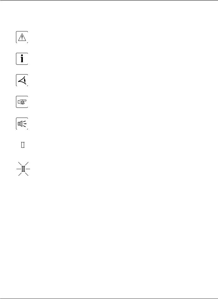
Symbol Usage
Important instructions that must always be followed.
Information, advice, help.
Visual indication.
Action.
Audible signal.
LED off
LED on
86-87050-00 A01 |
Introduction |
3 |

Pulsar MX
(This page left blank intentionally)
4 |
86-87050-00 A01 |
Presentation
1.1 Standard Positions
Tower Position
Dimensions (H x W x D) in inches/mm
Pulsar MX 5000 RT
17.5 x 5.16 x 29.2/
444.5 x 131 x 741.4
Pulsar MX EXB RT
17.5 x 5.16 x 25.6/
444.5 x 131 x 650
Transformer 5000
17.5 x 3.5 x 25.6/
444.5 x 88.9 x 650
Weights in lbs/kg |
|
|
|
Pulsar MX 5000 RT |
125/57 |
|
|
Pulsar MX EXB RT |
154/70 |
|
|
Transformer 5000 |
84/38 |
|
|
Rack Position
Dimensions (H x W x D) in inches/mm
Pulsar MX 5000 RT
5.16 x 17.5 x 29.2/
131 x 444.5 x 741.4
Pulsar MX EXB RT
5.16 x 17.5 x 25.6/
131 x 444.5 x 650
Transformer 5000
3.5 x 17.5 x 25.6/
88.9 x 444.5 x 650
Weights in lbs/kg
Pulsar MX 5000 RT |
125/57 |
|
|
Pulsar MX EXB RT |
154/70 |
|
|
Transformer 5000 |
84/38 |
|
|
86-87050-00 A01 |
Presentation |
1 — 1 |

Pulsar MX
1.2 Rear Panels
Pulsar MX 5000 RT
2
3
4
180VDdc |
CONNECTOR |
BATTERY |
|
LOAD UNDER |
CABLE BATTERY |
CAUTION: DISCONNECT NOT DO |
|
6 |
|
|
|
7 |
|
RS-232 |
BATT. NO. RPO |
|
|
|
Pulsar MX EXB RT
1 12
5 |
11 |
8
9
10
13
12
Transformer 5000
14
4 LOAD BREAKER |
3 LOAD BREAKER |
15
4 LOAD |
/ 3 LOAD |
120V~,16A / |
120V~,16A |
|
|
|
|
|
16 |
BREAKER |
2 LOAD |
|
1 LOAD BREAKER |
|
|
120V~,16A |
1 LOAD |
|
|
|
|
|
|
|
|
|
17 |
120V~,16A |
2 LOAD |
|
|
|
19 |
|
|
|
|
||
208~ |
240~ |
VOLTAGE INPUT SELECTION |
THIS SET WHEN SWITCH UNPOWERED SOURCES ALL BY |
|
18 |
|
|
|
BREAKER |
INPUT |
63 |
|
|
|
|
|
|
|
|
|
TRANSFORMER PROTECTION |
|
64 |
(1)One group of 4 L6-30R outlets for connection of equipment
(2)Output terminal block
(3)Normal AC source input cable with L6-30P
(4)Connector for additional battery module
(5)Slot for optional communication card
(6)USB communication port
(7)RS232 communication port
(8)Communication port by relay
(9)Connector for Remote Power Off control
(10)Connector for automatic detection of battery module(s)
(11)Connectors for automatic detection of battery module(s)
(12)Connectors for battery modules (to the UPS or to the other battery modules)
(13)DC Battery circuit breaker
(14)Resetable 20Amp circuit breakers for NEMA 5-15/20 receptacle
(15)6 NEMA 15/20 receptacle
(16)Resetable 20Amp circuit breakers to protect each L5-20R receptacle
(17)Input cable with L6-30P plug
(18)Input resetable CB
(19)2 NEMA L5-20R receptacle
(63)Input voltage selecting (240V/208)
(64)Transformer protection CB
1 — 2 |
Presentation |
86-87050-00 A01 |
Installation and User Manual
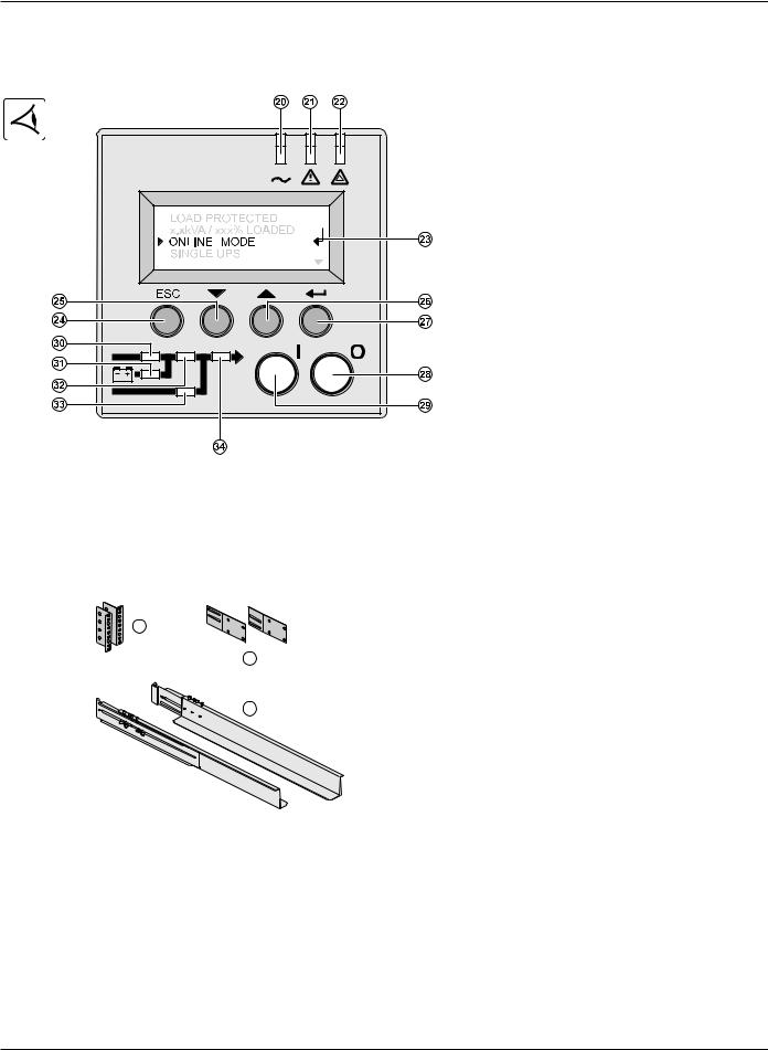
1.3 Display and Control Panel
(20) Load protected LED
(21) Downgraded operation LED
(22) Load not protected LED
(23) Alphanumeric display
(24) Escape (cancel) button
(25) Function buttons (scroll down)
(26) Function buttons (scroll up)
(27) Enter (confirm) button
(28) UPS OFF button
(29) UPS ON button
(30) Rectifier LED
(31) Battery LED
(32) Inverter LED
(33) Bypass LED
(34) Load supplied LED
1.4 Accessories for Rack Mount
Rack Mounting Kit
Telescopic rails for Pulsar MX RT mounting in 19’’ enclosure with mounting hardware
|
(35) |
Front mounting bracket |
35 |
(36) |
Rear support bracket |
|
(37) |
Telescopic rails, 639 mm to 1005 mm |
|
36 |
length (27.36’’ to 39.96’’) |
|
37 |
|
86-87050-00 A01 |
Presentation |
1 — 3 |
Pulsar MX
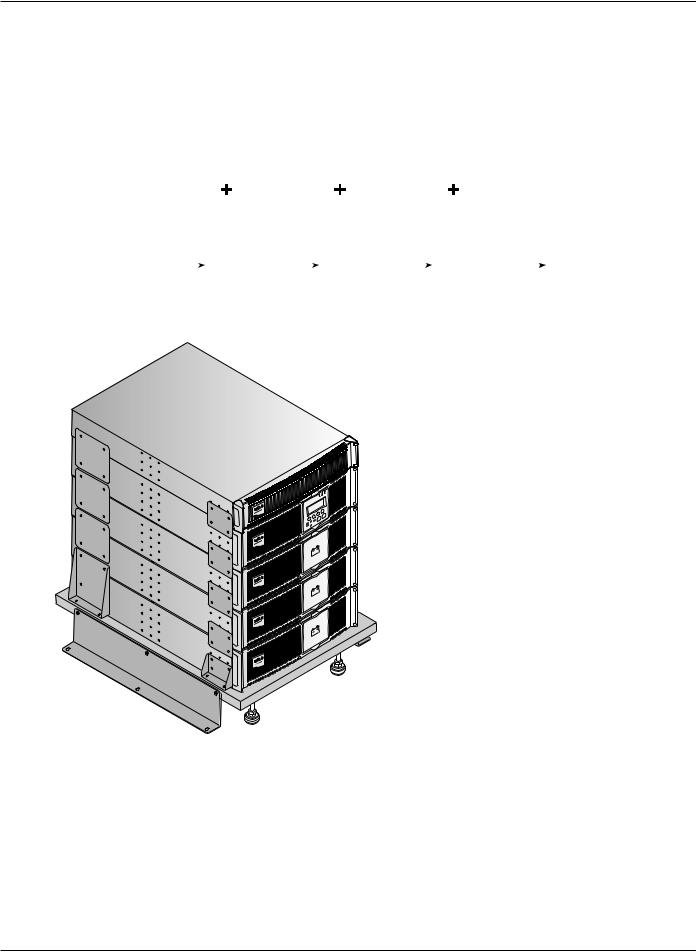
1.5Extended Battery (EXB)
Pulsar MX RT offers a standard backup time of 5 minutes at full load. To increase backup time, it is possible to connect Pulsar MX EXB RT modules to the UPSs for backup times up to 62 minutes (at full load).
Battery extensions for Pulsar MX RT
|
Pulsar MX |
|
|
Pulsar MX |
|
|
Pulsar MX |
|
|
Pulsar MX |
|
5000 RT |
|
|
EXB RT |
|
|
EXB RT |
|
|
EXB RT |
|
|
|
|
|
|
|
|
|
|
|
|
|
|
|
|
|
|
|
|
|
|
Pulsar MX 5000 RT: |
5 min |
22 min |
41 min |
62 min |
Battery Integration System Kit with Casters (86005)
The Battery Integration System is intended for extended backup time configurations to conveniently stack and secure up to 5 modules on the same cart (swivel wheels with brakes, leveling feet, seismic side panels, plates to lock modules, and screws included).
Optional battery extension cable (6 ft/1.8 m)
This extended battery cable will be used instead of the standard battery cable when battery modules are distant from each other (located in two different enclosures, for instance).
1 — 4 |
Presentation |
86-87050-00 A01 |
 Loading...