


www.mgeups.com |
MGE UPS SYSTEMS |
Pulsar EXtreme
2000/3000 VA
Installation and user manual
R
E
T
N
I
N
U
E
H
T
R
U
P
T
I
B
L
P |
O |
|
E
P
R
E
W
R |
O |
|
V
I
D
E
R
51033211EN/AC - Page 1
Introduction
Thank you for selecting an MGE UPS SYSTEMS product to protect your electrical equipment.
The Pulsar EXtreme range has been designed with the utmost care. We recommend that you take the time to read this manual to take full advantage of the many features of your UPS.
MGE UPS SYSTEMS pays great attention to the environmental impact of its products. Measures that have made Pulsar EXtreme a reference in environmental protection include:
Production in an ISO 14001 certified factory,
Recycling of Pulsar EXtreme at the end of its service life.
To discover the entire range of MGE UPS SYSTEMS products and the options available for the Pulsar EXtreme range:
We invite you to visit our Web site at www.mgeups.com
(page: www.mgeups.com/products/pdt230/smallups/extreme/extrem10.htm),Or contact your MGE UPS SYSTEMS representative.
Page 2 - 51033211EN/AC

Foreword
Using this document
Information may be found primarily by consulting:The contents,
The index.
Pictograms
Important instructions that must always be followed.
Information, advice, help.
Visual indication.
Action.
Audio indication.
In the illustrations on the following pages, the symbols below are used:
LED off.
LED on.
LED flashing.
51033211EN/AC - Page 3
Contents
1.Presentation
1.1 |
Pulsar EXtreme range ................................................................................................................. |
7 |
|
Tower model .................................................................................................................................... |
7 |
|
Rack model ..................................................................................................................................... |
7 |
1.2 |
Connection modules ................................................................................................................... |
8 |
|
Fault tolerant ................................................................................................................................... |
8 |
|
Hot swap ......................................................................................................................................... |
8 |
|
Install ............................................................................................................................................... |
8 |
1.3 |
Back ............................................................................................................................................. |
9 |
1.4 |
Options .......................................................................................................................................... |
9 |
|
Transformer for galvanic isolation or earthing arrangement change .............................................. |
9 |
|
Battery extensions for UPS backup times of 66 minutes ................................................................ |
9 |
|
CLA module (Long backup time charger) for backup times of 2 to 8 hours .................................. |
10 |
1.5 |
Control panel ............................................................................................................................... |
10 |
2.Installation
2.1 |
Unpacking and checks ............................................................................................................... |
12 |
|
"Tower" model ............................................................................................................................... |
12 |
|
"Rack" model ................................................................................................................................ |
13 |
2.2 |
Installation of the rack version .................................................................................................. |
14 |
2.3 |
Connection to the RS 232 communications port (optional) ................................................... |
15 |
2.4 |
Installation of the communications-card option ...................................................................... |
15 |
2.5 |
Securing and connecting the connection modules ................................................................. |
16 |
|
Securing the connection modules ................................................................................................. |
16 |
|
Fault tolerant ................................................................................................................................. |
16 |
|
Hot swap ....................................................................................................................................... |
17 |
|
Install ............................................................................................................................................. |
18 |
3.Operation
3.1 |
ON-LINE operating mode ........................................................................................................... |
19 |
3.2 |
Start-up ........................................................................................................................................ |
20 |
3.3 |
Bargraph indications .................................................................................................................. |
20 |
Page 4 - 51033211EN/AC
|
|
Contents |
3.4 Failure of AC input power and operation on battery power |
.................................................... 21 |
|
|
Transfer to battery power .............................................................................................................. |
21 |
|
Threshold for the low-battery shutdown warning .......................................................................... |
21 |
|
End of backup time ....................................................................................................................... |
21 |
|
Sleep mode ................................................................................................................................... |
21 |
|
Return of AC input power .............................................................................................................. |
21 |
3.5 |
Personalization ........................................................................................................................... |
22 |
|
Function ........................................................................................................................................ |
22 |
|
"ON / OFF conditions" tab ............................................................................................................. |
22 |
|
"Battery" tab .................................................................................................................................. |
23 |
|
"Output" tab ................................................................................................................................... |
23 |
|
"By-pass" tab ................................................................................................................................ |
23 |
3.6 |
Shutdown..................................................................................................................................... |
24 |
|
Shutdown of connected equipment............................................................................................... |
24 |
|
Complete shutdown of the UPS .................................................................................................... |
24 |
4.Maintenance
4.1 |
Troubleshooting .......................................................................................................................... |
25 |
4.2 |
UPS replacement ........................................................................................................................ |
27 |
|
Fault-tolerant connection module.................................................................................................. |
27 |
|
Hot-swap and Install connection modules .................................................................................... |
28 |
5. Environment ..................................................................................................................................... |
30 |
|
6.Appendices
6.1 |
Glossary....................................................................................................................................... |
31 |
6.2 |
Index............................................................................................................................................. |
33 |
51033211EN/AC - Page 5
1. Presentation
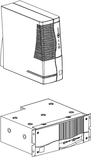
1.1 Pulsar EXtreme range
Tower model
|
Dimensions in mm |
|
(H x W x D) |
EXtreme 2000 - 3000 |
443 x 173 x 465 |
|
|
|
Weight in kg |
|
|
Pulsar EXtreme 2000 |
29 |
Pulsar EXtreme 3000 |
36 |
Rack model
|
Dimensions in mm |
|
(H x W x D) |
EXtreme 2000 - 3000 |
177 (4U) x 483 x 462 |
|
|
|
Weight in kg |
|
|
Pulsar EXtreme 2000 |
31 |
Pulsar EXtreme 3000 |
38 |
Page 6 - 51033211EN/AC
1. Presentation
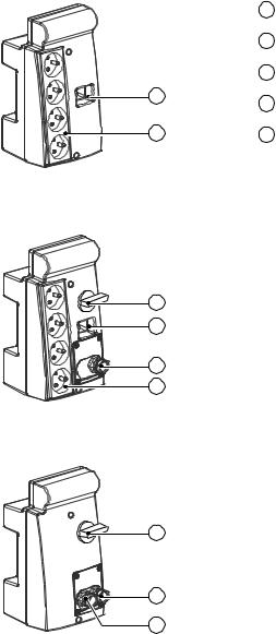
1.2 Connection modules
Fault tolerant
1 Socket for connection to AC-power source.
2 Outlets for direct connection to protected equipment.
3 Manual bypass switch.
1
4 Input terminal block with cable clamp.
2 |
5 Output terminal block with cable clamp. |
Hot swap
Install
Different types of sockets available on Fault tolerant and Hot swap
connection modules:
3 |
|
AC input cord |
Outlet sockets |
Power cords to |
|
|
|
|
|
equipment |
|
1 |
USE |
DIN plug, |
4 |
USE outlets (16A) |
|
|
2.5m cable, |
|
|
|
|
|
|
|
|
|
|
|
|
IEC320C20 cable |
|
|
|
|
|
|
|
|
|
5 |
DIN |
DIN plug, |
4 |
DIN outlets (16A) |
|
|
|
2.5m cable, |
|
|
|
2 |
|
IEC320C20 cable |
|
|
|
|
BS |
BS plug, |
4 |
BS outlets (13A) |
|
|
|
2.5m cable, |
|
|
|
|
|
IEC320C20 cable |
|
|
|
|
|
|
|
|
|
|
IEC |
IEC320C20 plug |
4 |
IEC320C13 outlets |
2 x |
|
|
(not supplied) |
(10A) protected by |
IEC320C13 plug, |
|
|
|
|
10A circuit breaker |
2.5m cable, |
|
|
|
|
and 1 IEC320C20 |
IEC320C13 plug |
|
|
|
|
outlet (16A) |
|
|
|
|
|
|
|
|
|
NEMA |
NEMA plug, |
4 |
NEMA outlets |
|
|
|
2.5m cable, |
(15A / 250V) |
|
|
3 |
|
IEC320C20 cable |
|
|
|
|
|
|
|
|
|
|
SWITZERLAND |
Swiss plug, |
4 |
IEC320C13 outlets |
2 x |
|
|
2.5m cable, |
(10A) protected by |
IEC320C13 plug, |
|
|
|
IEC320C20 cable |
10A circuit breaker |
2.5m cable, |
|
5 |
|
|
and 1 IEC320C20 |
IEC320C13 plug |
|
|
|
outlet (16A) |
|
||
|
|
|
|
||
|
|
|
|
|
|
4 |
AUSTRALIA |
AUSTRALIAN plug, |
4 AUSTRALIAN |
|
|
|
2.5m cable, |
outlets (16A) |
|
||
|
|
IEC320C20 cable |
|
|
|
|
|
|
|
|
|
51033211EN/AC - Page 7
1.Presentation
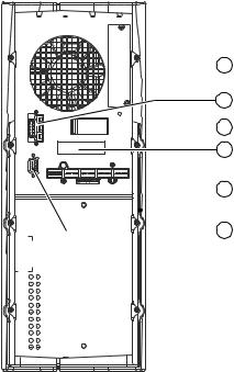
1.3Back
 6 Slot for communications-card option.
7 Battery module connector.

 8 Battery circuit breaker.
9 Rating plate.

 10 Connector for connection modules.
 11 RS232 communications port.
Page 8 - 51033211EN/AC
1. Presentation
1.4 Options
Transformer for galvanic isolation or earthing arrangement change
|
Pulsar EXtreme Transformer |
Nominal power |
3 kVA |
|
|
Nominal current |
16 A |
|
|
Input voltage |
230V (+15%, -20%) |
|
|
Voltage drop |
< 3% |
|
|
Frequency |
50/60 Hz (+/-10%) |
|
|
Isolation (EN 61558-1-2-4) |
3.75 kV / 5 M ohms |
|
|
Operating temperature |
From 0° to +40° C |
|
|
Max. operating rel. humidity |
95% |
|
|
Derating / altitude |
Pn-10% > 1000 m |
|
|
Natural ventilation |
IP20 ANAN |
Dimensions HxWxD (tower) |
443 x 173 x 465 mm |
Dimensions HxWxD (rack 4U) |
177 x 483 x 462 mm |
Weight (tower) |
24 kg |
Weight (rack) |
28 kg |
Important: to simplify installation, connect the Pulsar EXtreme Transformer downsteam of the UPSs. Visit our Web site: www.mgeups.com/products/pdt230/smallups/extreme/transfo.htm
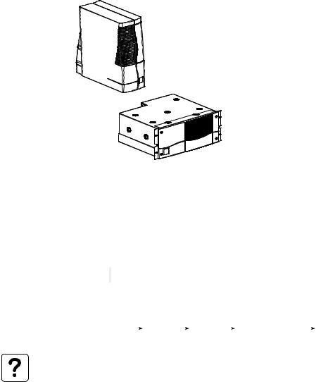
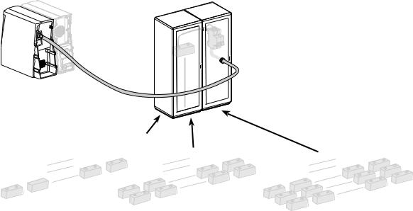
Battery extensions for UPS backup times of 66 minutes
Battery extensions for Pulsar EXtreme:
|
|
|
|
+ |
Pulsar |
+ |
Pulsar |
+ |
Pulsar |
Pulsar |
||||||
Pulsar |
EXtreme |
|||||||||||||||
EXtreme |
EXtreme |
EXtreme |
EXtreme |
|||||||||||||
|
|
|
|
|
|
EXB |
|
|
EXB |
|
|
EXB |
EXB |
|||
|
|
|
|
|
|
|
|
|
|
|
|
|
|
|
|
|
|
|
|
|
|
|
|
|
|
|
|
|
|
|
|
|
|
Pulsar EXtreme offers a standard backup time of 9 minutes.
To increase backup time, it is possible to connect Pulsar EXtreme EXB modules to the UPSs.
Visit our Web site: www.mgeups.com/ products/pdt230/smallups/extreme/ guide.htm.
9 min |
20 min |
36 min |
66 min |
The Pulsar EXtreme EXB modules are available in "tower" and in "rack" models. The Pulsar EXtreme EXB modules come with their connection cables.
51033211EN/AC - Page 9
1. Presentation
CLA module (Long backup time charger) for backup times of 2 to 8 hours
Very long backup times, from 2 to 8 hours at full load, require a Pulsar EXtreme CLA module (2000VA or 3000VA).
Visit our Web site: www.mgeups.com/products/pdt230/smallups/extreme/cla/cla2.htm.
Pulsar
 EXtreme
-65A |
h |
12V |
|
Pulsar
EXtreme
CLA
25A
2
12
1

-65Ah 12V
-65Ah 12V
6
9
-65A |
h |
12V |
|
2 h
|
20 |
00V |
A |
||
|
A |
||||
7 |
00 |
V |
|||
30 |
|||||
|
|||||
10 |
|
|
|||
|
|
|
|||
|
|
|
|
||
-65Ah |
|
|
2 |
||
12V |
|
|
|
|
|
12
1
|
-65Ah |
|
12V |
-65Ah |
-65Ah |
12V |
12V |
-65A |
h |
12V |
|
|
|
20 |
00V |
A |
|
|
|
A |
|||
|
7 |
00 |
V |
||
|
30 |
||||
6 |
|
||||
10 |
|
|
|||
|
|
|
|||
|
|
|
|
||
9 |
|
-65Ah |
|
|
|
|
|
|
|
|
|
|
12V |
|
|
|
|
-65A |
h |
-65Ah |
|
|
|
12V |
h |
12V |
|
|
|
|
-65A |
|
|
|
|
12V |
|
|
|
|
|
4 h
2
12
1
|
-65Ah |
|
|
|
12V |
|
|
-65Ah |
|
-65Ah |
|
12V |
|
12V |
h |
|
|
-65A |
|
12V |
|
|
|
|
12V |
|
|
|
-65A |
h |
|
|
12V |
|
|
|
|
|
|
20 |
00V |
A |
||
|
|
|
|
A |
||||
|
|
7 |
00 |
V |
||||
|
|
30 |
||||||
6 |
|
|
|
|||||
|
10 |
|
|
|
||||
|
|
|
|
|
||||
|
|
|
|
|
|
|||
9 |
|
|
-65Ah |
|
|
|
|
|
|
|
|
|
|
|
|
||
|
|
h |
12V |
|
|
|
|
|
|
-65A |
|
-65Ah |
|
|
|
||
12V |
|
h |
12V |
-65A |
h |
|||
|
|
-65A |
|
|||||
|
|
|
|
|
||||
|
12V |
|
h |
12V |
|
|
||
|
|
|
-65A |
|
|
|
|
|
|
|
12V |
|
|
|
|
|
|
8 h
Page 10 - 51033211EN/AC
1. Presentation
1.5 Control panel
|
|
Alarms |
% battery |
% load |
|
|
|
remaining |
|
|
14 |
UPS overload |
100% |
100% |
|
15 |
Electronics fault |
80% |
80% |
|
16 |
Battery fault |
50% |
50% |
|
17 |
Ambient temp. |
20% |
20% |
|
|
> 40° C |
|
|
|
18 |
Hold down to display |
|
|
|
|
percent load. |
|
|
|
19 |
Lamp test or buzzer OFF. |
|
|
|
20 |
Operation on manual bypass. |
|
|
bypass |
21 |
Operation on automatic bypass. |
|
|
|
22 |
Operation in ON-LINE mode. |
|
|
|
23 |
Operation on battery power. |
|
|
|
24 |
ON/OFF. |
|
|
51033211EN/AC - Page 11
 Loading...