

Page 1

IC equipment
Wall-Jet cell
Manual
8.110.8015EN / 2013-12-12
Page 2

Page 3

Metrohm AG
CH-9100 Herisau
Switzerland
Phone +41 71 353 85 85
Fax +41 71 353 89 01
info@metrohm.com
www.metrohm.com
IC equipment
Wall-Jet cell
6.5337.0x0
8.110.8015EN / 2013-12-12
Manual
zst
Page 4

Teachware
Metrohm AG
CH-9100 Herisau
teachware@metrohm.com
This documentation is protected by copyright. All rights reserved.
Although all the information given in this documentation has been
checked with great care, errors cannot be entirely excluded. Should you
notice any mistakes please send us your comments using the address
given above.
Documentation in additional languages can be found on
http://documents.metrohm.com.
Page 5

■■■■■■■■■■■■■■■■■■■■■■
Table of contents
1 Introduction 1
1.1 Description ............................................................................ 1
1.2 About the documentation ................................................... 1
1.2.1 Content and scope .................................................................. 1
1.2.2 Symbols and conventions ........................................................ 2
2 Overview 4
3 Installation 5
3.1 Inserting the working electrode .......................................... 5
3.2 Inserting the reference electrode ........................................ 6
3.3 Connecting the detector capillaries .................................... 8
3.4 Connecting the electrode cables ....................................... 10
Table of contents
4 Start-up 12
5 Operation and maintenance 13
5.1 Operation ............................................................................ 13
5.2 Maintenance ....................................................................... 13
5.2.1 Replacing the working electrode ............................................ 13
5.2.2 Replacing the reference electrode .......................................... 14
5.2.3 Replacing the spacer .............................................................. 15
5.2.4 Cleaning the measuring cell ................................................... 17
6 Technical specifications 20
6.1 General ................................................................................ 20
6.2 Wall-Jet cell for carbohydrate analysis ............................. 21
6.3 Wall-Jet cell for cyanide analysis ....................................... 21
6.4 Wall-Jet cell for anion analysis .......................................... 22
7 Accessories 23
Index 25
IC equipment Wall-Jet cell
■■■■■■■■
III
Page 6

Table of figures
Table of figures
Figure 1 Wall-Jet cell – Parts and connections ................................................. 4
Figure 2 Inserting the working electrode ......................................................... 5
Figure 3 Ag/AgCl reference electrode (6.1257.720) ......................................... 7
Figure 4 Disassembling the measuring cell .................................................... 16
■■■■■■■■■■■■■■■■■■■■■■
■■■■■■■■
IV
IC equipment Wall-Jet cell
Page 7

■■■■■■■■■■■■■■■■■■■■■■
1 Introduction
1.1 Description
The Wall-Jet cell is used for amperometric detection with the Amperometric Detector. The Wall-Jet cell applies the wall-jet principle, which means
that the inlet is positioned directly opposite the working electrode. A thin
vertical jet of eluate is directed onto the working electrode, thus enabling
an optimum measurement performance.
The IC equipment Wall-Jet cell is available in four versions:
■ Wall-Jet cell without electrodes (6.5337.000).
■ Wall-Jet cell Carb (6.5337.010), with one gold working electrode and
one palladium reference electrode for the analysis of sugars and amino
acids.
■ Wall-Jet cell Cyanide (6.5337.020), with one silver working electrode
and one palladium reference electrode for applications relating to environmental analysis, e.g. the determination of cyanide and sulfide.
■ Wall-Jet cell Anion (6.5331.030), with one glassy carbon working elec-
trode and one silver / silver chloride reference electrode for the analysis
of inorganic anions, e.g. nitrite, sulfite and iodide.
1 Introduction
A more detailed description of the specifications and areas of application
for the individual cells can be found in Chapter 6, page 20.
1.2 About the documentation
CAUTION
Please read through this documentation carefully before putting the
measuring cell into operation. The documentation contains information
and warnings which the user must follow in order to ensure safe operation of the instrument.
1.2.1 Content and scope
Content of this manual
This manual describes:
■ how to insert the working electrode in the Wall-Jet cell.
■ how to insert the reference electrode in the Wall-Jet cell.
■ how to connect the capillaries and the electrode cables.
■ how users can carry out maintenance work.
IC equipment Wall-Jet cell
■■■■■■■■
1
Page 8
1.2 About the documentation
■ the technical specifications of the Wall-Jet cell.
■ the supplied and the optional accessories.
Additional information
Detailed information concerning the insertion of the measuring cell into
the detector can be found in the manuals for the amperometric detector.
Information on the use, care and maintenance of the working electrodes
and reference electrodes can be found in the leaflets enclosed with the
electrodes.
1.2.2 Symbols and conventions
The following symbols and formatting may appear in this documentation:
■■■■■■■■■■■■■■■■■■■■■■
Cross-reference to figure legend
The first number refers to the figure number, the second to the instrument part in the figure.
Instruction step
Carry out these steps in the sequence shown.
Method Dialog text, parameter in the software
File ▶ New Menu or menu item
[Next] Button or key
WARNING
This symbol draws attention to a possible life-threatening hazard or risk of injury.
WARNING
This symbol draws attention to a possible hazard due
to electrical current.
WARNING
This symbol draws attention to a possible hazard due
to heat or hot instrument parts.
WARNING
This symbol draws attention to a possible biological
hazard.
CAUTION
■■■■■■■■
2
This symbol draws attention to possible damage to
instruments or instrument parts.
IC equipment Wall-Jet cell
Page 9

■■■■■■■■■■■■■■■■■■■■■■
1 Introduction
NOTE
This symbol highlights additional information and
tips.
IC equipment Wall-Jet cell
■■■■■■■■
3
Page 10
2 Overview
1
2
3
4
6
8
9
5
5
7
■■■■■■■■■■■■■■■■■■■■■■
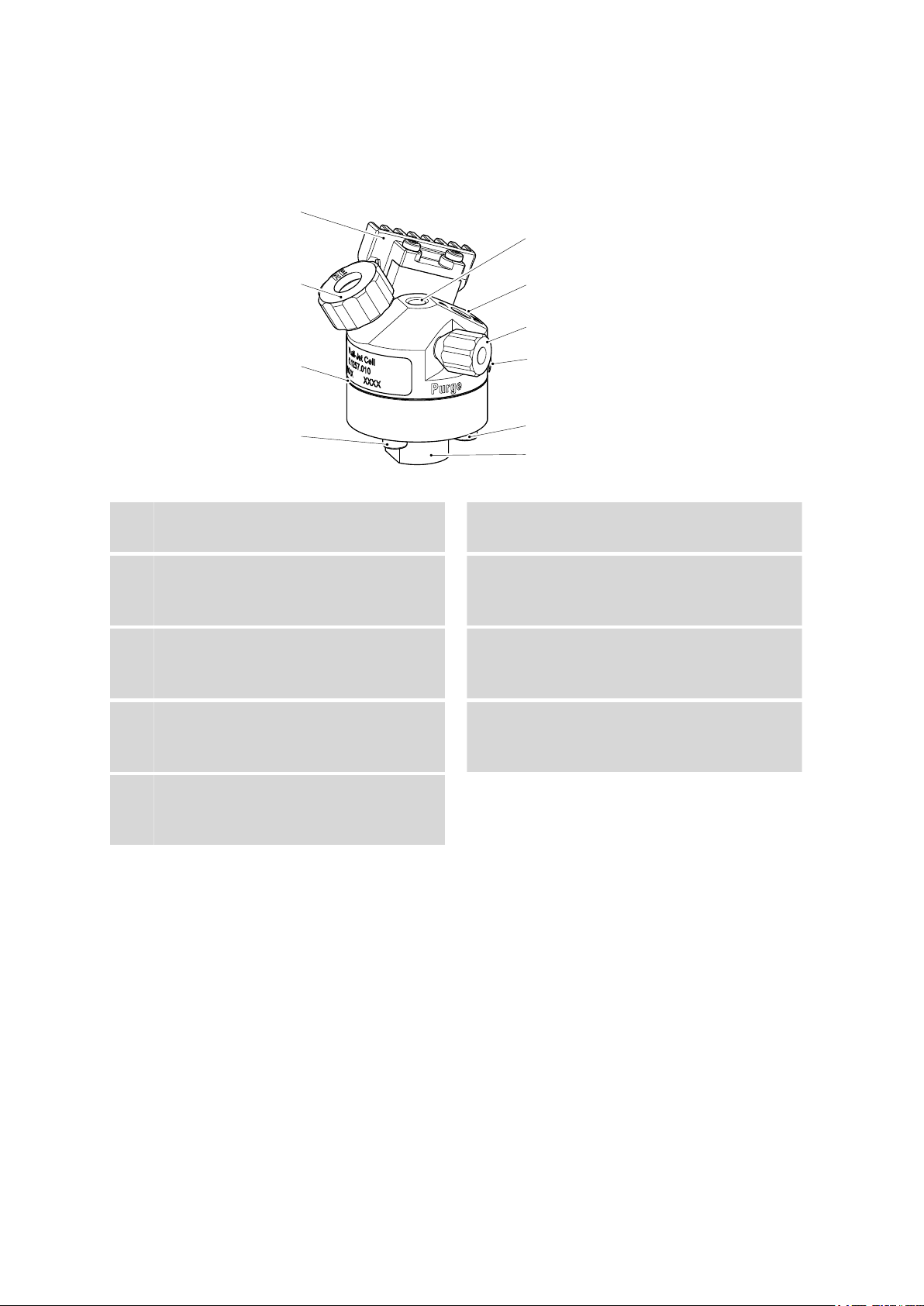
Figure 1 Wall-Jet cell – Parts and connections
Eluent inlet
1
Labeled In.
Stopper
3
For deaeration opening.
Screws (4x)
5
For assembling the Wall-Jet cell.
Spacer
7
Standard: 50 µm (6.1257.810).
Chip
9
Intelligent. For hanging the Wall-Jet cell in
the detector.
Eluent outlet
2
Labeled Out.
Electrode cable connection socket
4
For the auxiliary electrode cable. Labeled
AE.
Pressure screw
6
For fixing the working electrode (WE) in
place.
Fastening screw
8
For fixing the reference electrode in place.
Labeled RE.
■■■■■■■■
4
IC equipment Wall-Jet cell
Page 11

■■■■■■■■■■■■■■■■■■■■■■
3 Installation
CAUTION
Never switch on the measuring cell …
■ … if it is not simultaneously being rinsed by a conductive eluent; or
■ … if the electrode cables are not completely connected.
3.1 Inserting the working electrode
The measuring cell is supplied without electrodes. The working electrode
is either included in your equipment or you have ordered it separately.
Insert the working electrode as follows:
3 Installation
Inserting the working electrode
Figure 2
1
Inserting the working electrode
Unscrew the pressure screw on the base part of the cell and remove
it.
Insert the working electrode in the opening. The working electrode is
2
formed in such a way that it can be inserted into the measuring cell
in only one position.
Slide the pressure screw over the working electrode and screw it
3
tightly.
IC equipment Wall-Jet cell
■■■■■■■■
5
Page 12

3.2 Inserting the reference electrode
3.2 Inserting the reference electrode
The measuring cell is supplied without electrodes. The reference electrode
is either included in your equipment or you have ordered it separately.
Insert the reference electrode as follows:
Inserting the reference electrode
The reference electrode itself and one sealing ring are contained in the
packaging for the reference electrode.
Slide the sealing ring over the reference electrode.
1
■■■■■■■■■■■■■■■■■■■■■■
Unscrew the fastening screw on the RE connector and remove it.
2
Insert the reference electrode into the opening with the flat side fac-
3
ing downward.
Retighten the fastening screw.
4
Special case: Ag/AgCl reference electrode
The Ag/AgCl reference electrode (6.1257.720) is, in contrast to the other
reference electrodes, permanently connected to the reference electrode
cable.
■■■■■■■■
6
IC equipment Wall-Jet cell
Page 13

■■■■■■■■■■■■■■■■■■■■■■
1
2
4
5
3
3 Installation
Figure 3 Ag/AgCl reference electrode (6.1257.720)
Plug
1
Sealing screw
3
For sealing the storage vessel.
Storage vessel
5
For storing the Ag/AgCl reference electrode.
Insert the reference electrode as follows:
Inserting the Ag/AgCl reference electrode
Take the Ag/AgCl reference electrode out of the storage vessel. Pull
1
the sealing screw of the storage vessel over the plug and reseal the
storage vessel with it.
Reference electrode cable
2
Permanently mounted on the reference electrode.
Reference electrode
4
IC equipment Wall-Jet cell
■■■■■■■■
7
Page 14

3.3 Connecting the detector capillaries
Unscrew the fastening screw from the reference electrode holder.
2
Push the fastening screw over the cable of the Ag/AgCl reference
electrode.
Check whether the sealing ring is seated on the reference electrode
3
and insert the reference electrode into the reference electrode
holder.
Tighten the reference electrode to the reference electrode holder
4
with the fastening screw.
Further information regarding the correct handling of the Ag/AgCl reference electrode can be found in the leaflet for the Ag/AgCl reference electrode.
3.3 Connecting the detector capillaries
■■■■■■■■■■■■■■■■■■■■■■
The amperometric detector is equipped with a preheating capillary in its
interior to ensure that the eluent flows through the measuring cell at a
constant temperature.
Connecting the preheating capillary is optional. If the ambient conditions
are optimal or if the eluent is heated in the column, then the measuring
results can be sufficiently accurate, even without the use of the preheating
capillary.
CAUTION
The preheating capillary may not be connected if highly flammable liquids are analyzed!
In the event of a leak, the fluid might evaporate and ignite in the heating area.
If the preheating capillary is not used, proceed as follows:
Connecting capillaries to the measuring cell
1
Connecting the cell inlet
Use a pressure screw (6.2744.014) to fasten the detector input capillary to the In connector of the measuring cell.
■■■■■■■■
8
IC equipment Wall-Jet cell
Page 15

■■■■■■■■■■■■■■■■■■■■■■
2
Connecting the cell outlet
Use a pressure screw (6.2744.014) to fasten a piece of PEEK capillary
(6.1831.010) with a length of 1 to 1.5 m to the Out connector of
the measuring cell.
NOTE
This capillary must be tested with the IC instrument the first time
the detector is put into operation, see the chapter "Start-up" in
the manual for the detector.
If the preheating capillary is used, proceed as follows:
Connecting capillaries to the measuring cell
1
Connecting the preheating capillary
3 Installation
NOTE
The preheating capillary must be tested with the IC instrument the
first time the detector is put into operation, see the chapter "Start-
up" in the manual for the detector.
■ Use a pressure screw (6.2744.014) to connect the detector input
capillary to the Eluent in connector of the detector.
■ Use a pressure screw (6.2744.014) to fasten a piece of PEEK capil-
lary (6.1831.010) to the Eluent to cell connector of the detector.
2
Connecting the cell inlet
Use a pressure screw (6.2744.014) to fasten the other end of the
PEEK capillary (6.1831.010) to the In connector of the measuring
cell.
3
Connecting the cell outlet
Use a pressure screw (6.2744.014) to fasten a piece of PEEK capillary
(6.1831.010) with a length of 1 to 1.5 m to the Out connector of
the measuring cell.
IC equipment Wall-Jet cell
■■■■■■■■
9
Page 16

3.4 Connecting the electrode cables
NOTE
This capillary must be tested with the IC instrument the first time
the detector is put into operation, see the chapter "Start-up" in
the manual for the detector.
3.4 Connecting the electrode cables
CAUTION
The electrode cables may not be plugged or unplugged unless the measuring cell is switched off in the software.
NOTE
■■■■■■■■■■■■■■■■■■■■■■
The sockets and the plugs of the cables must be clean and dry.
Connecting the electrode cables to the detector
Prerequisites:
■ The measuring cell is switched off.
Plug the straight plug of the working electrode cable (red sleeve) into
1
the WE socket of the detector.
Plug the straight plug of the reference electrode cable (black sleeve)
2
into the RE socket of the detector.
Plug the straight plug of the auxiliary electrode cable (blue sleeve)
3
into the AE socket of the detector.
■■■■■■■■
10
IC equipment Wall-Jet cell
Page 17

■■■■■■■■■■■■■■■■■■■■■■
3 Installation
Connecting the electrode cables to the measuring cell
Prerequisites:
■ The working electrode and the reference electrode are inserted into
the measuring cell.
Plug the angled plug of the working electrode cable (labeled WE)
1
into the working electrode socket.
Plug the angled plug of the reference electrode cable (labeled RE)
2
into the reference electrode socket.
Plug the angled plug of the auxiliary electrode cable (labeled AE) into
3
the socket (labeled AE).
IC equipment Wall-Jet cell
■■■■■■■■
11
Page 18

4 Start-up
■■■■■■■■■■■■■■■■■■■■■■
The measuring cell and the amperometric detector are set to work at the
same time. Additional information on this topic can be found in the manual for the detector.
■■■■■■■■
12
IC equipment Wall-Jet cell
Page 19

■■■■■■■■■■■■■■■■■■■■■■
5 Operation and maintenance
5.1 Operation
The measuring cell is operated together with the detector and the entire
IC system with the MagIC Net™ software.
Additional information on operation with MagIC Net™ can be found in
the "MagIC Net™ Tutorial" or in the MagIC Net™ online help.
5.2 Maintenance
The measuring cell must be taken out of the detector for the following
maintenance tasks.
CAUTION
5 Operation and maintenance
The electrode cables may not be unplugged unless the measuring cell is
switched off in the software!
Taking the measuring cell out of the detector
Switch off the measuring cell in the software.
1
Disconnect all three electrode cables.
2
On the measuring cell holder, push the Press button and remove the
3
measuring cell from the holder.
5.2.1 Replacing the working electrode
Depending on the application, the measuring cell can be operated with a
variety of different working electrodes. The different working electrodes
are available as accessories (see Chapter 7, page 23).
Replacing the working electrode
IC equipment Wall-Jet cell
Prerequisites:
■ The measuring cell is switched off.
■ The measuring cell has been removed from the detector.
■ The electrode cables are unplugged.
■■■■■■■■
13
Page 20

5.2 Maintenance
■■■■■■■■■■■■■■■■■■■■■■
No tool is required for replacing the working electrode.
Unscrew the pressure screw (1-6) on the base part of the cell and
1
remove it.
Take out the working electrode.
2
Insert the new working electrode. The working electrode is shaped in
3
such a way that it can be inserted into the measuring cell in only one
position.
Slide the pressure screw over the working electrode and tighten it.
4
5.2.2 Replacing the reference electrode
Depending on the application, the measuring cell can be operated with a
variety of different reference electrodes. The different reference electrodes
are available as accessories (see Chapter 7, page 23).
NOTE
These instructions apply analogously to the Ag/AgCl reference electrode.
Inserting the reference electrode
Prerequisites:
■ The measuring cell is switched off.
■ The measuring cell has been removed from the detector.
■ The electrode cables are unplugged.
No tool is required for replacing the reference electrode.
Slide the supplied sealing ring over the new reference electrode.
1
■■■■■■■■
14
IC equipment Wall-Jet cell
Page 21

■■■■■■■■■■■■■■■■■■■■■■
5 Operation and maintenance
Unscrew the fastening screw for the reference electrode and remove
2
it.
Take out the reference electrode.
3
Insert the new reference electrode.
4
Tighten the fastening screw again.
5
NOTE
Important: After an Ag/AgCl reference electrode has been
removed!
The Ag/AgCl reference electrode may not be allowed to dry out. Follow
the directions for storage contained in the leaflet for the Ag/AgCl reference electrode.
5.2.3 Replacing the spacer
Depending on the application, the measuring cell can be operated with a
variety of different spacers. The different spacers are available as accessories (see Chapter 7, page 23).
The measuring cell must be disassembled in order for the spacer to be
replaced. Proceed as follows to disassemble the measuring cell:
Disassembling the measuring cell
Prerequisites:
■ The measuring cell is switched off.
IC equipment Wall-Jet cell
■■■■■■■■
15
Page 22

5.2 Maintenance
1
2
3
4
■■■■■■■■■■■■■■■■■■■■■■
■ The measuring cell has been removed from the detector.
■ The electrode cables have been removed.
To disassemble the measuring cell, you need a 2.5 mm hex key.
Fastening screw (4x)
1
Spacer
3
6.1257.810 or 6.1257.830.
Figure 4 Disassembling the measuring cell
Base part
2
Measuring part
4
With auxiliary electrode.
Remove the reference electrode.
1
Remove the working electrode.
2
Unscrew the four screws on the base part of the measuring cell with
3
the hex key and remove them.
Remove the base part.
4
Remove the spacer.
5
Replace the spacer as follows:
■■■■■■■■
16
IC equipment Wall-Jet cell
Page 23

■■■■■■■■■■■■■■■■■■■■■■
5 Operation and maintenance
Replacing the spacer
Prerequisites:
■ The measuring cell is disassembled.
■ The new spacer is dry, clean and lint-free.
You will need a 2.5 hex key and a pair of tweezers to replace the spacer.
Wear latex gloves when replacing the spacer.
1
Positioning the spacer
■ Hold the measuring part in your hand as shown in Figure 4, page
16.
■ Use tweezers to place the new spacer on the measuring part.
The straight side of the spacer must lie on the straight edge of the
measuring part and the four small holes in the spacer must be
aligned precisely to the boreholes.
Use your fingertips to hold the spacer in correct position.
2
Attaching the base part
■ Insert the four screws into the boreholes on the base part.
■ Carefully mount the base part of the measuring cell:
The straight edge of the base part must lie on the straight edge of
the measuring part and the four screws must fit precisely in the
four boreholes.
Take care to ensure that the boreholes on the base part, the spacer
and the measuring part are aligned precisely with one another.
3
Tightening the screws
Tighten the four screws evenly in crosswise sequence with the hex
key.
5.2.4 Cleaning the measuring cell
The auxiliary electrode can be readily cleaned when the working electrode
has been removed from the cell.
IC equipment Wall-Jet cell
■■■■■■■■
17
Page 24

5.2 Maintenance
■■■■■■■■■■■■■■■■■■■■■■
Cleaning the auxiliary electrode
Prerequisites:
■ The electrode cables are unplugged.
■ The reference electrode has been removed from the measuring cell.
■ The working electrode has been removed from the measuring cell.
1
NOTE
When cleaning the auxiliary electrode, the edges of the spacer
may get damaged.
The spacer must then be replaced.
■ Moisten a cotton swab with 2 mol/L of nitric acid.
■ Use this to carefully wipe the auxiliary electrode.
The edges of the spacer may be damaged when wiping the auxiliary electrode.
If the auxiliary electrode is tenaciously stained, we recommend
that the spacer be removed prior to cleaning the auxiliary electrode (see Chapter 5.2.3, page 15).
■■■■■■■■
18
Rinse off the measuring cell (except for the working electrode and
2
the reference electrode) under running water and dry with a lint-free
cloth.
NOTE
When you rinse off the measuring part, take care to ensure that
the chip in the cell holder does not get wet.
IC equipment Wall-Jet cell
Page 25

■■■■■■■■■■■■■■■■■■■■■■
5 Operation and maintenance
Cleaning the working electrode
Clean the working electrode in accordance with the directions con-
1
tained in the leaflet for the working electrode or polish it if necessary.
Reinsert the working electrode (see Chapter 3.1, page 5).
2
Inserting the reference electrode
Reinsert the reference electrode (see Chapter 3.2, page 6).
1
IC equipment Wall-Jet cell
■■■■■■■■
19
Page 26

6.1 General
■■■■■■■■■■■■■■■■■■■■■■
6 Technical specifications
6.1 General
Structure Flow-through cell with working, reference and auxiliary electrode.
Material Cell body made of PEEK.
Cell volume Dependent on the thickness of the spacer:
for 3 mm working electrode
and 50 µm
spacer
for 2 mm working electrode
and 25 µm
spacer
< 0.35 µL
< 0.1 µL
Maximum operating pressure
Cell recognition Intelligent cell with automatic identification and monitoring.
Auxiliary electrode
Type Installed
Material Stainless steel
Reference electrode
Type Replaceable
Material ■ Palladium solid-state electrode
0.4 MPa (100 psi)
■ Ag/AgCl gel electrode
■■■■■■■■
20
IC equipment Wall-Jet cell
Page 27

■■■■■■■■■■■■■■■■■■■■■■
6.2 Wall-Jet cell for carbohydrate analysis
Working electrode
Material Gold
Diameter 3 mm
6 Technical specifications
Reference elec-
Palladium solid-state electrode
trode
Applications Sugar and amino acids
■ Mono-, di-, oligo- and polysaccharides
■ Sugar alcohols
■ Amino sugars
■ Sugar acids
■ Amino acids
■ Antibiotics
Working range
Acidic medium
(pH 1)
Ag/AgCl refer-
–0.35 V - +1.10 V
ence electrode
Alkaline
medium (pH 13)
Palladium refer-
–0.9 V - +0.75 V
ence electrode
6.3 Wall-Jet cell for cyanide analysis
Working electrode
Material Silver
Diameter 3 mm
Reference electrode
Applications Applications relating to environmental analysis
IC equipment Wall-Jet cell
Palladium solid-state electrode
■ Halogenides
■ Cyanide, sulfide
■ Thiosulfate
■ Pharmaceuticals
■■■■■■■■
21
Page 28

6.4 Wall-Jet cell for anion analysis
Working range
Acidic medium
(pH 1)
Ag/AgCl refer-
–0.55 V - +0.40 V
ence electrode
Alkaline
medium (pH 13)
Palladium refer-
–1.2 V - +0.1 V
ence electrode
6.4 Wall-Jet cell for anion analysis
Working electrode
Material Glassy carbon
Diameter 3 mm
■■■■■■■■■■■■■■■■■■■■■■
Reference elec-
Ag/AgCl gel electrode
trode
Applications Aromatics and amines
■ Catecholamines, aromatic amines
■ Inorganic anions (nitrite, sulfite, etc.)
■ Phenols
■ Vitamins
■ Some amino acids
Working range
Acidic medium
(pH 1)
Ag/AgCl refer-
–0.8 V - +1.3 V
ence electrode
Alkaline
medium (pH 13)
Ag/AgCl refer-
–1.5 V - +0.6 V
ence electrode
■■■■■■■■
22
IC equipment Wall-Jet cell
Page 29

■■■■■■■■■■■■■■■■■■■■■■
7 Accessories
Up-to-date information on the scope of delivery and optional accessories
for your instrument can be found on the Internet.
When you receive your new instrument, we recommend downloading
the accessories list from the Internet, printing it out and keeping it
together with the manual for reference purposes.
Instruments currently sold
If you do not know the article number of your instrument, proceed as follows:
Downloading the accessories list
7 Accessories
NOTE
Go to the Metrohm website http://www.metrohm.com/com.
1
2
Click on .
The Search webpage will be displayed.
Enter a search term relating to the instrument into the search field
3
and click on Find.
The search results will be displayed.
In the search results, select the Devices tab (if it is not already
4
selected) and then click on the Metrohm article number of the
required instrument (e.g. 2.852.0050).
The page with information pertaining to the searched article is displayed.
Select the Parts tab.
5
The complete list of accessories with the scope of delivery and the
optional accessories will be displayed.
6
Click on .
IC equipment Wall-Jet cell
■■■■■■■■
23
Page 30

■■■■■■■■■■■■■■■■■■■■■■
The Partslists webpage will be displayed.
Select the desired output language.
7
With the article number entered, click on the command Generate
8
PDF.
The PDF file with the accessories data will be created in the language
selected.
Direct access for all instruments
If you are unable to find your instrument using the search as described
above, this may be due to the instrument not being sold anymore. Using
the article number, you can download accessories lists for all instruments
as follows:
Downloading the accessories list
Type http://partslists.metrohm.com into your Internet browser.
1
The Partslists webpage will be displayed.
Select the desired output language.
2
Enter the article number and click on the Generate PDF command.
3
The PDF file with the accessories data will be created in the language
selected.
■■■■■■■■
24
IC equipment Wall-Jet cell
Page 31

■■■■■■■■■■■■■■■■■■■■■■
Index
Index
A
Auxiliary electrode
Cleaning ............................. 17
E
Electrode cable
Connect ............................. 10
I
Installation
Insert Ag/AgCl reference elec-
trode .................................... 7
Insert reference electrode ..... 6
Insert working electrode ....... 5
Measuring cell ...................... 5
M
Measuring cell
Cleaning ............................. 17
Connect capillaries ................ 8
Remove .............................. 13
Take out ............................. 13
R
Reference electrode
Installation ........................... 6
Replace .............................. 14
S
Spacer
Replace .............................. 15
T
Technical specifications ............ 20
W
Wall-Jet cell
Anion analysis .................... 22
Carbohydrate analysis ......... 21
Cyanide analysis ................. 21
Technical specifications . 21, 22
Working electrode .................... 17
Inserting ............................... 5
Replace .............................. 13
IC equipment Wall-Jet cell
■■■■■■■■
25
 Loading...