


Microcook HD2025
Merrychef Microcook HD2025, TA, Microcook HD1725, Microcook HD1925, Microcook 1025 Service Manual
...
Page 1 Microcook HD Ovens 32Z3385 Issue 5
CAUTION MICROWAVE EMISSIONS
DO NOT BECOME EXPOSED TO EMISSIONS FROM THE MICROWAVE
GENERATOR OR PARTS CONDUCTING MICROWAVE ENERGY
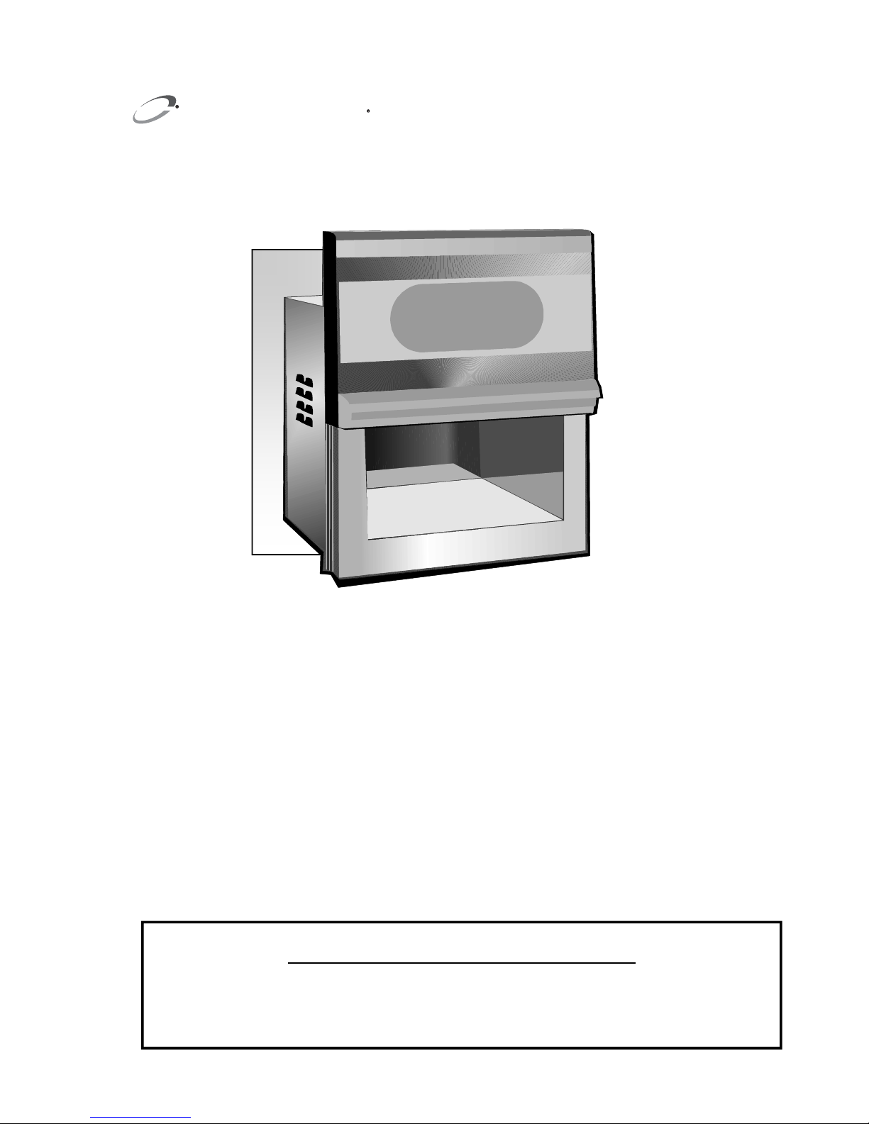
Microcook HD
Microcook TA
SERVICE MANUAL
SERVICE MANUAL
For all Microcook HD & TA models manufactured from January 2001
Part No. 32Z3385 Issue No. 5
Merr ychef

Page 2 Microcook HD Ovens 32Z3385 Issue 5
Table of Contents
Safety Code...........................................................................3
Microcook HD Specification Sheet ........................................4
Microcook TA Specification Sheet…………….............. …….5
Installation Instructions ..........................................................6
Error Codes & Diagnostics ....................................................7
Power Output Test Procedure A............................................8
Simplified Power Output Test B.............................................9
Transformer / Capacitor Test Procedure C & D ..................10
Rectifier Test Procedure E ..................................................11
Door Interlock Operation .....................................................11
Oven Main Features ............................................................12
Rear Cover Assembly.........................................................13
Door Assembly 500mm Die Cast ........................................14
Door Assembly 650mm .......................................................15
Control Panel Assembly ......................................................16
Component Layout HD1025 ................................................17
Component Layout HD1425 / 1725 .....................................18
Component Layout HD1925 ................................................19
Component Layout HD2025…………………..... …………...20
Component Layout TA 1725, TA 1925 ................................21
Cavity Components .............................................................22
Door Mechanism Right side ................................................23
Door Mechanism Left side...................................................24
Hot Air Motor Assembly.......................................................25
Microcook TA Fan Control PCB and Heater Setup ...... 26-27
Input Wiring Details .............................................................28
Part Number Identification List ...................................... 29-30
Wiring Diagrams ............................................................ 31-35
Appendix 1 KFC components .............................................36
Appendix 2 Capacitors and Magnetrons .............................37
Appendix 3 Cleaning ..........................................................38
Appendix 4 MenuKey download ..........................................39
Appendix 5 Fitting 20A Anti surge fuses........................ 40-41
Appendix 6 Logic board and Magnetron Failure Detect ......42
Manual Corrections and Modifications ................................43
Merrychef Limited,
Station Road West,
Ash Vale, Aldershot,
Hampshire, GU12 5XA
United Kingdom
Tel: +44 (0)1252 371000 Fax: +44 (0)1252 371007
Internet address: http://www.merrychef.com
E-mail: sales@merrychef.com or service@merrychef.com

Page 3 Microcook HD Ovens 32Z3385 Issue 5
This manual is designed to assist engineers who have successfully completed a Merrychef
Service training course. It has been prepared to offer technical guidance for the Merrychef
Microcook HD and Microcook TA Commercial Microwave Ovens.
Please remember that it is wiser not to attempt a service task if you are unsure of being able to
complete it competently, quickly, and above all safely.
To avoid injury to yourself, and to protect the appliance from possible damage, please follow
this Safety Code when servicing these ovens.
Before attempting to repair the oven, check it for microwave leakage.
Check that the oven is not emitting microwaves,
even when supposedly not in operation.
Check that the oven is not operating continuously,
whether the display indicates cooking or not.
Always discharge the HT capacitors before working on the oven
using a suitably insulated 10 MΩ Resistor
The following must be carried out prior to removing the rear cover from the oven :
• Switch off the mains supply and remove the plug from the wall socket.
or
• If the oven is hard wired, ensure that the power is turned off at the mains
isolator switch.
Upon completion of a service on an Microcook oven, or before reconnecting the appliance to
the mains supply for testing, check all of the following points:
• All internal electrical connections are correct.
• All wiring insulation is correct and is not touching a sharp edge.
• All Earth connections are electrically and mechanically secure.
• All three door safety interlocks are secure and mechanically sound.
• The door operation is smooth.
• The door activates all three of the door interlock switches in the correct order.
• All fuse-holder safety covers are correctly fitted.
Before finishing the service call, recheck the following points:
• The oven is electrically safe
• All of the electronics are functioning correctly, and all of the touch pads are
working.
• The power output of the oven is correct (see pages (8 & 9).
• Microwave emission is below permissible limit - 5 mW/cm²
(see BS EN 60335-2-90).
• Oven has correct 50mm air gap all round. Air flow should not be restricted.
SAFETY CODE

Page 4 Microcook HD Ovens 32Z3385 Issue 5
Power
Requirements
Model HD1025
Model HD1425
Model HD1725
Model HD1925
Model HD2025
1.75kW
2.60kW
2.88kW
3.12kW
Power Output Microwave 100%
1025W (IEC 705)
1425W (IEC 705)
1725W (IEC 705)
1925W (IEC 705)
External
Dimensions
Height
Width
Depth
475mm (Plus 50mm minimum clearance above)
496mm (Plus 50mm minimum clearance each side)
499mm (Plus 50mm clearance behind)
Internal
Dimensions
Height
Width
Depth
Capacity
200mm
390mm
365mm
28.5 Litres ( 1.01ft³)
Weight Nett
Gross packed
42.5kg
45kg
Construction Cavity
Casework
304 Stainless Steel
304 Stainless Steel
Coated Aluminium extrusions
Settings Microwave
Timer
100%,50%, Defrost
Up to 10 minutes
Up to 3 cooking stages of up to 10 minutes each Program
Model Number: Model prefix + Type + Voltage + Frequency + UK/Export + Customer
For example: 1925C450UK
Model 1925, Microcook, 230-240V, 50Hz, UK model
Product specifications:
Model
prefix
Type Frequency UK/Export
1025
1425
1725
1925
2025
C= Cook
V=Vend
50 = 50 Hz
60 = 60 Hz
UK = UK model
EX = Export model
Voltage
2= 220-230V a.c.
4= 230-240V a.c
Customer
KFC
FP = Feastpoint
BL = Bourne Leisure
Microcook HD1025, HD1425, HD1725, HD1925 & HD2025
Microcook HD Series
Page 5 Microcook HD Ovens 32Z3385 Issue 5
Power
Requirements
TA1725
TA1925
3.12kW
5.50kW ( 3.12kW + 2.38kW )
Power Output
TA1725
Microwave 100%
Hot Air
Combination
TA1925
Microwave 100%
Hot Air
Combination
1725W (IEC 705)
1400W
865W Microwave plus 1400W Hot Air
1925W (IEC 705)
2000W
1925W Microwave plus 2000W Hot Air
Power supply lead
TA1725
TA1925
13 Amp plug BS 1363A ( UK only )
2 x 13 Amp plug BS 1363A ( UK only )
or 1 x 30Amp cable with plug BS4343 ( UK only )
External
Dimensions
Height
Width
Depth
475mm (Plus 50 mm minimum clearance above)
496mm (Plus 50 mm minimum clearance each side)
499mm (Plus 50 mm clearance behind)
Internal
Dimensions
Height
Width
Depth
Capacity
200mm
390mm
365mm
28.5 Litres ( 1.01ft³)
Weight Nett
Gross packed
42.5kg
45kg
Construction Cavity
Casework
304 Stainless Steel
304 Stainless Steel
Coated Aluminium extrusions
Settings Microwave
Timer
TA1725 100%,50%, turbo
TA1925 100%, heat only, turbo
Up to 9 minutes 59 seconds
Up to 3 Programmed cooking stages of up to 9 minutes
59 seconds each ( total 29 minutes 57 seconds)
Model Number: Model prefix + Turbo + Voltage + Frequency + Type
Model
prefix
Turbo
Frequency
Type
TA1725
TA1925
MT = Manual Turbo
VT = Vend Turbo
5 = 50 Hz
6 = 60 Hz
UK = UK model
EX = Export model
EE = Twin 13amp Lead
EX = Single 30 amp Lead
Voltage
2= 220-230V a.c.
4= 230-240V a.c
Product specifications:
Microcook TA1725 & TA1925
Microcook TA Series
Page 6 Microcook HD Ovens 32Z3385 Issue 5
Installation instructions
Power Supply Requirements
The Microcook HD & Microcook TA ovens should be connected to a suitable electricity
supply, which can cope with the switching-on surge that occurs with certain types of
catering equipment, such as microwaves. Because of this requirement, we strongly
recommend that a separate, suitably rated supply is installed for the oven.
The supply for the oven should be fitted with a Type "C" circuit breaker, rated at 16A.
Positioning the Oven
In order to maintain adequate ventilation for air intake and exhaust, and to allow access
for cleaning filters, you must allow a minimum of 50mm clearance all around the oven. Air
intake temperature should not exceed 35°C - excessive temperature can lead to reduced
operating duty cycle or premature ageing of internal components.
NEVER Install an oven above fryers, grills, griddles or any other major heat
source.
NEVER Stack machines on top of each other
ALWAYS Place containers in the cavity carefully - impact damage may chip the
oven shelf.
Note:
The 840mm clearance at the front allows the
complete removal of the door for cleaning
A – HD2025 Model
B – HD1025 Model
Page 7 Microcook HD Ovens 32Z3385 Issue 5
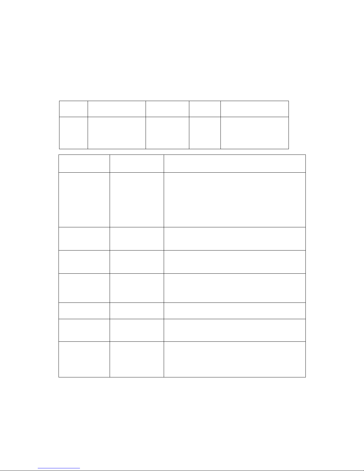
Display Fault (frequency) Recommended Action
1
2
Door not fully closed
(permanent)
Magnetron
overheating
(Intermittent)
Check the door is fully closed.
Check the door down LED is illuminated on the control
board.
Check ribbon connector condition and fit.
Ensure the oven has been
installed correctly.
Check the magnetron cooling fan is operating and free
from obstruction.
1
2
3
Membrane panel
failure
(permanent)
Membrane panel
failure
(Intermittent)
Incorrect time set.
( Intermittent )
Replace membrane panel.
Replace membrane panel.
Check correct time is set
ie : 1.00 minute Not 60 seconds
Error codes and diagnostics
The Microcook will identify some of the most common problems by flashing an error message code
in the time display window.
These are the error messages, and suggestions for repairing them:
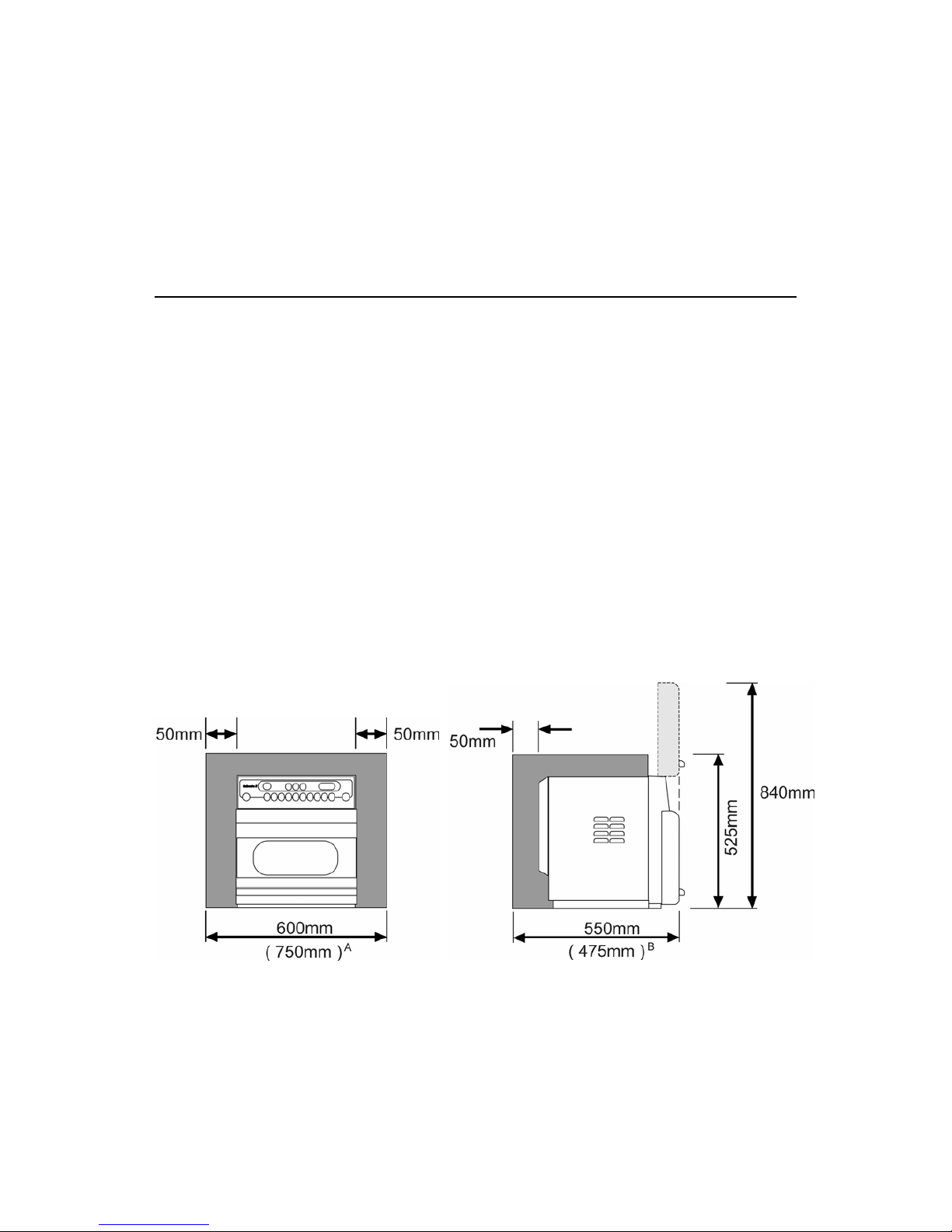
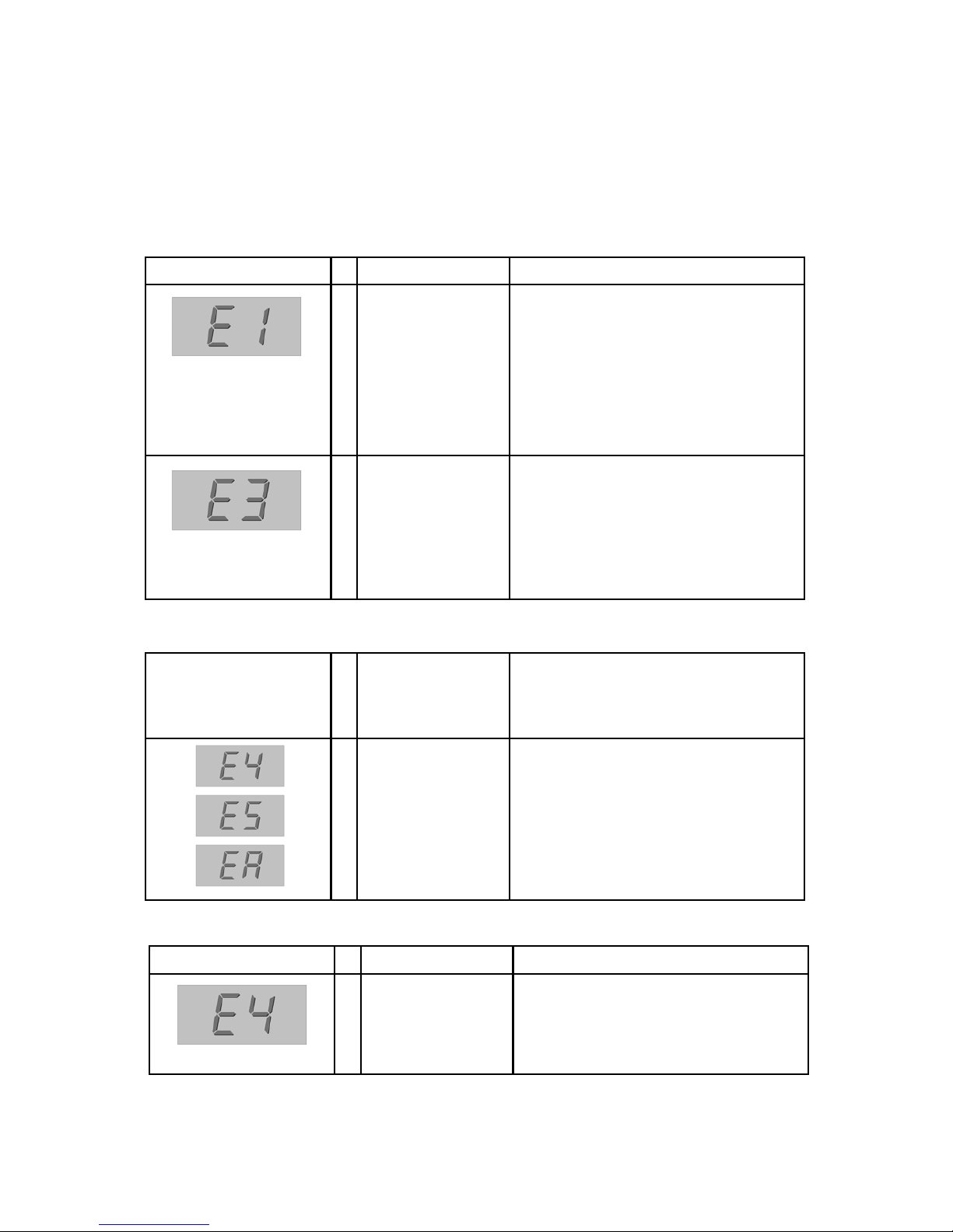
Display Fault (frequency) Recommended Action
1
2
Microcook TA
Convected hot air
failure (permanent)
Intermittent
Check full / half wave LED
on control board
Check heating element
TA Models
KFC HD Models (with Fibre Optic Magnetron Detection)
Display Fault (frequency) Recommended Action
LH Magnetron Failure
RH Magnetron Failure
Both magnetrons have
failed
Check Power supply
Replace magnetron(s)
All HD & TA Models

Page 8 Microcook HD Ovens 32Z3385 Issue 5
Procedure A - Power Output Test in accordance with
BS EN 60335-2-90 Annex AA
This test is given in the BSI test standard for microwave ovens. It is reproduced below - not so that
you can follow it, but to show you why it is impractical in normal conditions. A simplified procedure,
which gives a good approximation to the BSI power output, is given in Procedure B which follows.
Note: This test can only be carried out on a COLD oven. If the oven has been operating, even for
only a few seconds, the power given will be lower than the oven rating. This test must also be
carried out at a stable voltage - the voltage in most kitchens varies considerably even within the
period of the test. If the oven has been operating, go to Procedure B.
You will need:
A thermometer capable of reading to ±0.1°C.
A cylindrical borosilicate glass container, 190mm diameter, with a wall thickness of
3mm or less.
A calculator.
A set of scales capable of reading 1kg to an accuracy of ± 1g.
A glass or plastic stirrer.
A jug capable of holding over 1litre of water.
Drinkable water which is at a temperature of 10°C ± 1°C.
A “Variac” or similar variable transformer capable of supplying the oven to ensure
a stable voltage.
WARNING: The Borosilicate Glass container has thin walls and is therefore fragile
- take care not to break it during use.
Method
A cylindrical container of borosilicate glass is used for the test. It has a maximum thickness of
3mm, an external diameter of approximately 190mm and a height of approximately 90mm. The
mass of the container is determined.
At the start of the test, the oven and the empty container are at ambient temperature. Potable water
having an initial temperature of 10°C ± 1°C is used for the test. The temperature of the water is
measured immediately before it is poured into the container.
A quantity of 1000g ± 5g of water is added to the container and its actual mass obtained. The
container is then immediately placed in the middle of the oven shelf which is in its lowest normal
position. The appliance is supplied at rated voltage and operated at the maximum power setting.
The time for the water temperature to attain 20°C ± 2°C is measured. The oven is then switched off
and the final water temperature is measured within 60’seconds.
NOTES: 1. The water is stirred before its temperature is measured.
2. Stirring and measuring devices are to have a low heat capacity.
The microwave power output is calculated from the formula:
where
P is the microwave power output, in watts;
M
W
is the mass of the water, in grams;
M
C
is the mass of the container, in grams;
T
0
is the ambient temperature, in °C;
T
1
is the initial temperature of the water, in °C;
T
2
is the final temperature of the water, in °C;
t is the heating time in seconds, excluding the magnetron filament heat-up time.
4.187 MW (T2-T1) + 0.55 MC (T2-T0)
t
P =
Page 9 Microcook HD Ovens 32Z3385 Issue 5
Procedure B - Simplified Power Output Test
You will need:
A thermometer capable of reading to ±0.1°C.
A Polypropylene tray approximately 200mm x 200mm.
A measuring jug.
A calculator.
Water which is at a temperature of 10°C ± 2°C.
1 Measure 1 litre of cold water into the tray using the measuring jug.
2 Measure the water temperature, and record it as T[s].
3 Place the tray on the turntable in the oven and close the door.
4 Turn the oven on.
5 Set the timer to 1:02.
6 Press the “100%” power pad.
7 When the oven bleeps, open the door and remove the tray.
8 Stir the water thoroughly, and measure its temperature. Record this as T[e].
Calculation:
1 T[r] = T[e] - T[s]
2 Power = 70 x T[r]. Power is in Watts
The power given by the above test should be within ±10% of the rated power.
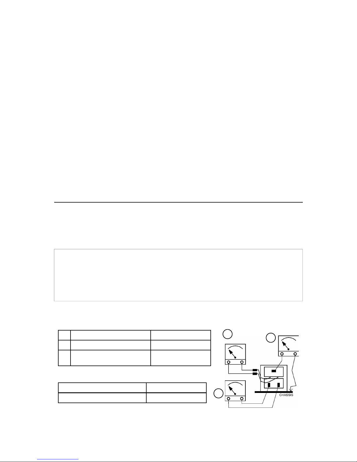
Procedure C - Power Transformer Test
You will need:
A Digital Multi-meter (D.M.M.)
A Megger or similar resistance meter using 500V d.c.
1 Isolate the oven from the mains supply.
WARNING: High voltages and large currents are present at the secondary winding and filament
winding of the Power Transformer. It is very dangerous to work near this part when the
oven is on. NEVER make any voltage measurements at the High Voltage circuits,
including the magnetron filament.
WARNING: Even when the oven is not cooking, the Power Transformer has High Voltages present
because of the Soft Start circuit. Isolate the oven before testing.
a Mains winding between tags
Approx. 1.3 Ω
b High Voltage winding
Approx. 82 Ω
c Filament winding
between terminals
Less than 1 Ω
Primary winding and chassis
Pass if over 10 MΩ
Filament winding and chassis
Pass if over 10 MΩ
2 Ensure that the High Voltage Capacitor is discharged before commencing work.
3 Remove all connections from the Power Transformer.
4 Using a D.M.M., check the continuity of the windings. Results should be as follows:
5 Using a Megger, test the insulation resistance between:
One end of the High Voltage winding is connected to the
chassis, so this is not tested.
a
c
b
Page 10 Microcook HD Ovens 32Z3385 Issue 5
Procedure E - High Voltage Rectifier Test
You will need:
A Megger or similar resistance meter using 500V d.c.
WARNING: High voltages and large currents are present at the High Voltage Rectifier. It is very
dangerous to work near this part when the oven is on. NEVER make any voltage
measurements at the High Voltage circuits, including the magnetron filament .
WARNING: Even when the oven is not cooking, the High Voltage Rectifier has High Voltages
present because of the Soft Start circuit. Isolate the oven before testing.
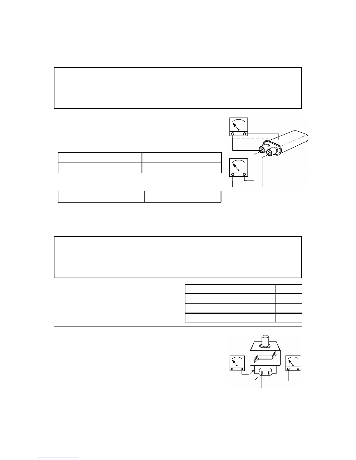
Procedure D - High Voltage Capacitor Test
You will need: A Digital Multi-meter (D.M.M.)
A Megger or similar resistance meter using 500V d.c.
5. Using a Megger, test the insulation resistance between the
terminals and the case.
1. Isolate the oven from the mains supply.
2. Ensure that the High Voltage Capacitor is discharged before
commencing work.
3. Remove all connections from the High Voltage Capacitor.
4. Using a D.M.M., check for continuity between the terminals &
compare results with table.
WARNING: High voltages and large currents are present at the High Voltage Capacitor. It is very
dangerous to work near this part when the oven is on. NEVER make any voltage
measurements at the High Voltage circuits, including the magnetron filament .
WARNING: Even when the oven is not cooking, the High Voltage Capacitor has High Voltages
present because of the Soft Start circuit. Isolate the oven before testing.
Between Terminals
Pass if approximately 10 MΩ
Between Terminals and Case Pass if open circuit
Between Terminals and Case
Pass if over 100 MΩ
Procedure F - Magnetron Test
You will need:
A Megger or similar resistance meter using 500V d.c.
A Magnetron can be tested for an open filament or a short circuit
by carrying out a continuity check.
1. Isolate the oven from the mains supply.
2. Ensure that the High Voltage Capacitor is discharged before
commencing work.
3. Remove all connections from the Magnetron.
4. A continuity check across the Filament terminals should be 1ohm or less
5. A continuity check between each filament terminal and the
metal outer should read open.
1. Isolate the oven from the mains supply.
2. Ensure that the High Voltage Capacitor is
discharged before commencing work.
3. Remove all connections from the High Voltage
Rectifier.
4. Using the Megger, test for continuity in both
directions. Compare results with the table.
Open Circuit both ways
FAIL
Conducts one way only
PASS
Short Circuit both ways
FAIL
Conducts one way, leaks the other
FAIL
Page 11 Microcook HD Ovens 32Z3385 Issue 5
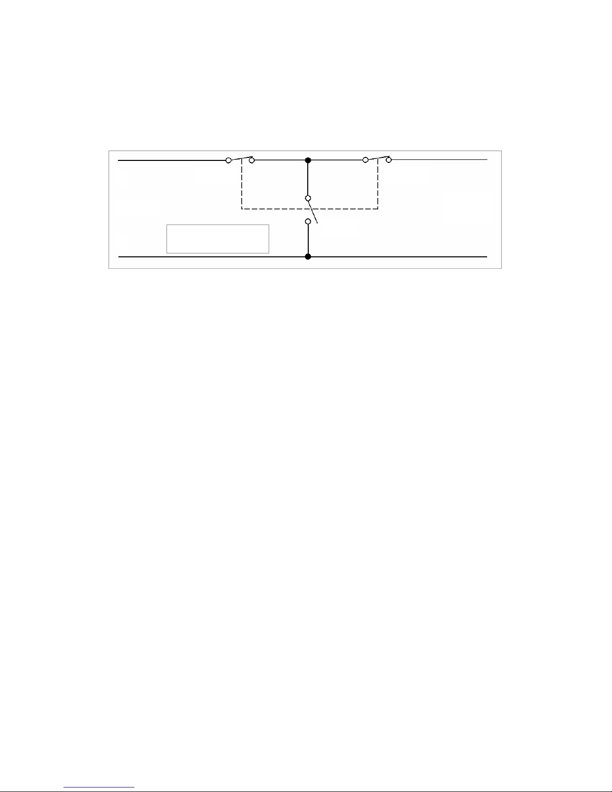
Door interlock operation
The door on the Microcook oven is monitored by three microswitches used in the conventional
“Primary, Secondary and Monitor” switch arrangement shown below.
Door Interlock
Arrangement
Monitor
Secondary
Power In
Power
Out
L
N
Primary
The switches operate as follows:
1. Monitor Switch [TopRight]. As the door is closed, the monitor switch is opened.
2. Primary Interlock Switch [ Bottom Left ]. The Primary switch is then closed.
3. Secondary Interlock Switch [ Bottom Right ]. The Secondary Switch then closes.
When the door is opened, the switches operate in the reverse order.
Page 12 Microcook HD Ovens 32Z3385 Issue 5
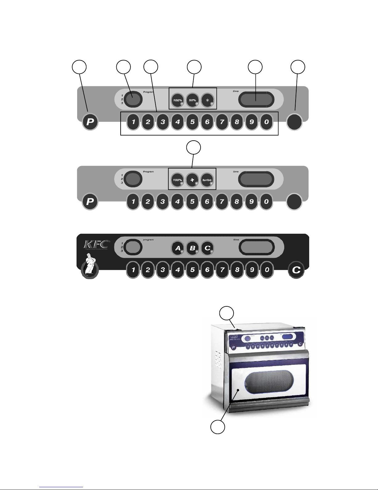
Main features
Description of Features
a. Program Pad
b. On/Off Switch
c. Program Display
d. Program Selection / Time Set Pads
e. Power Selection Pads
HD models:100%, 50% & de-frost
TA models:100%, hot-air & turbo
f. Time Display
g. Cancel / Callback Pad
h. Door
h
b
C
micro
cook
a c
d
f
g
e
turbo
aire ll
C
e
Vend model (KFC)
Page 13 Microcook HD Ovens 32Z3385 Issue 5
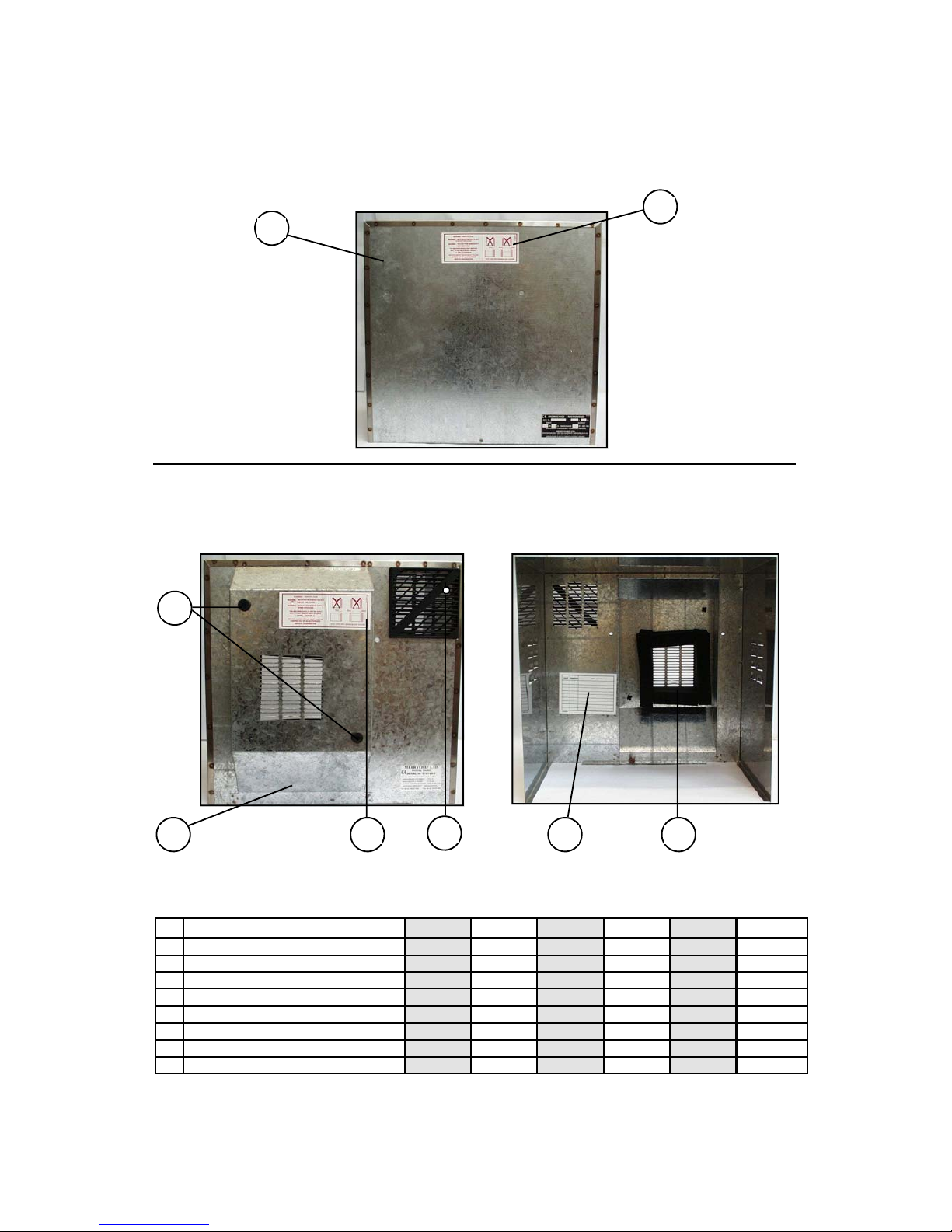
No Description HD1025 HD1425 HD1725 HD1925 HD2025 TA
1 Rear Cover 40M0883 11M0269 11M0269 11M0269 11M0270 11M0269
2 Push Fit Feet —– 31Z1187 31Z1187 31Z1187 31Z1187 31Z1187
3 Air filter —– 31Z1104 31Z1104 31Z1104 31Z1104 31Z1104
4a Screw M5x16 31Z3022 31Z3022 31Z3022 31Z3022 31Z3022 31Z3022
4b M5 Star Washer 31Z5012 31Z5012 31Z5012 31Z5012 31Z5012 31Z5012
5 Installation Label 31Z2071 31Z2071 31Z2071 31Z2071 31Z2071 31Z2071
6 Self Adhesive Foam Tape —– 31Z0158 31Z0158 31Z0158 31Z0158 31Z0158
7 Service History Label 31Z2056 31Z2056 31Z2056 31Z2056 31Z2056 31Z2056
Rear cover assembly
HD1025 only Rear View
All other models
Outer View
Inner View
1
5
1
2
5
3
7 6
 Loading...