


e4s
Service & Parts Manual original Instructions
Part Number 32Z3871 US
Issue 3
1
eikon
TM
CAUTION MICROWAVE EMISSIONS:
DO NOT BECOME EXPOSED TO EMISSIONS FROM THE
MICROWAVE GENERATOR OR PARTS CONDUCTING
MICROWAVE ENERGY.
Service & Parts Manual
eikon e4s

SYMBOLS
The symbols below are used, where applicable, as visual guidance throughout this manual.
DANGER
This symbol is shown if there is a high risk of severe personal physical injury. The relevant safety precautions MUST
be observed and implemented at all times.
WARNING
This symbol is shown if there is a possible risk of personal physical injury or if damage may occur to the equipment.
The relevant safety precautions MUST be observed and implemented at all times.
INFORMATION
This symbol is used to highlight useful or important information. For example: The manual consists of main sections
(tab markers on the extreme left and right of the pages), followed by the main subject heading, sub-headings and
text. Text with a reference number or letter, such as (1) refers to the same reference on the image.
1
2
Service & Parts Manual original Instructions
art Number 32Z3871 US
P
Issue 3
Service & Parts Manual original Instructions
Part Number 32Z3871 US
Issue 3
3
SAFETY &
REGULATIONS
PRODUCT
DETAILS
TESTING
COMPONENTS
SERVICINGSPARES &
REPLACEMENT
FAULT FINDINGELECTRICAL
CIRCUITS
COMMISSIONING
CONTENTS
SAFETY & REGULATIONS
1 SAFETY REQUIREMENTS 4
1.1 Important: 4
PRODUCT DETAILS
2 PRODUCT OVERVIEW & FUNCTIONS 5
3 MAIN FEATURES 6
4 TECHNICAL SPECIFICATIONS 7
4.1 Speci cations 7
4.2 Serial Number (Rating Plate): 7
5 INSTALLATION 8
5.1 OVEN LOCATION AND POSITIONING 8
6 ELECTRICAL INSTALLATION 9
7 QUICK START GUIDE: QUICK SERVICE OVEN 10
7.1 START UP 10
7.2 USING A COOKING PROGRAM 11
8 OPERATING GUIDE: FULL SERVICE OVEN 12
8.1 easyToUCH MAIN MENU & KEYBOARD SCREEN 12
8.2 DEVELOPMENT MODE: CREATING A COOK PROGRAM 13
8.3 PRESS & GO 14
8.4 USING A COOKBOOK PROGRAM 14
8.5 CHANGING THE OVEN TEMPERATURE 15
8.6 VIEWING & EDITING PROGRAMS 15
8.7 ADDING A NEW PROGRAM GROUP 16
8.8 MOVE A PROGRAM WITHIN A PROGRAM GROUP 16
8.9 ADDING A PROGRAM TO A GROUP 17
8.10 MANAGING PROGRAM GROUPS 17
9 OVEN CONTROL SETTINGS 18
9.1 Oven mode/navigation settings (A) 18
9.2 Language options (B) 18
9.3 Oven temperature settings and labels (C) 18
9.4 Recipe counters (E) 19
9.5 Date and Time settings (F) 19
9.6 Sound levels (G) 19
9.7 Oven Timer (H) 19
9.8 USB oven programs (J) 20
9.9 Temperature Band (K) 20
9.10 Change Password (L) 20
9.11 Screen saver (M) 20
10 COOLING THE OVEN DOWN BEFORE CLEANING 21
10.1 Oven cool down 21
10.2 Preparing to clean the oven 21
11 Cold oven CLEANING INSTRUCTIONS e4s 22
SERVICING
12 SERVICING THE OVEN 23
12.1 Servicing Procedure: 23
12.2 Enter Service mode: 23
13 ERRORS & DIAGNOSTICS 24
13.1 ERROR MESSAGES 24
13.2 COPYING ERROR MESSAGES: 24
13.3 ERROR LOG 24
13.4 OVEN COUNTERS 24
13.5 VISUAL VIEW 25
14 FIRMWARE UPDATES 26
TESTING COMPONENTS
15 OVEN TESTING 29
15.1 Equipment required 29
15.2 Earth/Insulation Test: 29
15.3 Screen calibration: 29
15.4 OVEN TESTS 30
15.5 Microwave Power Test 30
15.6 Microwave Leakage Test 31
15.7 Temperature Control Test 32
15.8 Soak Test 33
15.9 Recommission Test 33
16 HIGH VOLTAGE COMPONENTS 34
16.1 Power Transformer Test 34
16.2 High Voltage Recti er Test (Diode) 34
16.3 High Voltage Capacitor Test 35
16.4 High Voltage Magnetron Test 35
17 MAINS VOLTAGE COMPONENTS 36
17.1 Door Interlock Adjustment 36
17.2 Convection Fan Motor & Controller 37
SPARES & REPLACEMENT
18 OVEN COMPONENTS 38
19 SRB & QTS Circuit Boards 40
19.1 SRB replacement 40
19.2 QTS replacement 40
19.3 PM (Personality Module) replacement 41
20 SPARE PARTS EXPLODED VIEW 42
21 SPARE PARTS 43
FAULT FINDING
22 ERROR CODES DISPLAYED 45
ELECTRICAL CIRCUITS
23 SRB & QTS Circuit Boards 47
23.1 QTS LEDs 47
23.2 QTS Terminal Locations 47
23.3 SRB LED’s 48
23.4 SRB Terminal Locations: 49
24 CIRCUIT DIAGRAMS 50
24.1 POWER CONNECTIONS e4s 52
24.2 CONTROL CIRCUIT e4s 53
24.3 HEATER CIRCUIT e4s 54
24.4 MICROWAVE CIRCUIT e4s 55
COMMISSIONING
25 Commissioning the oven 56
25.1 Initial installation 56
25.2 After Service 56
4
Service & Parts Manual original Instructions
P
art Number 32Z3871 US
Issue 3
SAFETY &
REGULATIONS
1.1 Important:
This manual provides technical guidance for engineers
who have successfully undertaken a recognised product
familiarisation and training course run by Merrychef to carry
out service/repair tasks to the appliance/s shown on the front
cover of this manual which must not be used for any other
make or model of appliance.
Please remember that it is wiser not to attempt a service task
if you are unsure of being able to complete it competently,
quickly, and above all safely.
To avoid injury to yourself or others and to protect the
appliance from possible damage, ensure you have read and
understand all the relevant instructions and ALWAYS follow the
Safety Codes when servicing an oven.
1.1.1 Before attempting to repair the oven, check the oven for
microwave emissions using a calibrated microwave emission
detector.
1.1.2 Check that the oven is not emitting microwaves, even
when supposedly not in operation.
1.1.3 Check that the oven is not operating continuously, whether
the display indicates cooking or not.
1.1.4 Never manipulate the mains power lead whilst it is live.
1.1.5 Before removing the oven casing ALWAYS isolate the
oven from the mains electricity power supply; switch o and
disconnect the oven plug from the wall socket, turn o isolator
switch to disconnect xed wired ovens. NOTE: The oven switch
does not provide adequate protection against electric shock as it
does not isolate all of the internal wiring from the mains.
1.1.6 Ensure Electrical supply is locked-o to prevent the oven
from being inadvertently powered up.
1.1.7 Do not leave the oven unattended without the oven panels
tted and keep within sight of other personnel when testing the
oven, ensuring persons other than trained engineers are denied
access.
1.1.8 The minimum number of panels should be removed and
the HT capacitors must be discharged before working on the
oven using a suitably insulated 10 MΩ Resistor.
1.1.9 Temporary insulation should be used to prevent accidental
contact with dangerous conductors.
1.1.10 Do not touch any internal wiring or connectors within the
Oven, whether you believe it is live or not and avoid touching the
Metalwork (Casing, Panels, etc) of the Oven with your Body.
1.1.11 Only use electrically rated screwdrivers for adjusting ‘Pots’
etc., ensuring the tool touches nothing else.
1.1.12 Ensure the Test Equipment is set correctly before use.
1.1.13 Test equipment such as meter test leads or clamps must
be tted and removed whilst the unit is dead, for each and every
test.
1.1.14 Do not undertake functional Magnetron testing with the
oven panels removed.
1.1.15 Avoid touching the Test Equipment, unless necessary for
the operation.
1.1.16 Upon completion of a service follow the steps for
‘Commissioning the oven’ under the Commissioning section of
this manual.
1 SAFETY REQUIREMENTS
DANGER:
BEFORE REMOVING THE OVEN CASING, ISOLATE
THE OVEN FROM THE MAINS ELECTRICITY
POWER SUPPLY; SWITCH OFF, DISCONNECT
OVEN PLUG FROM WALL SOCKET, TURN OFF
ISOLATOR SWITCH TO DISCONNECT FIXED
WIRED OVENS AND LOCKOFF.
WARNING:
ALWAYS DISCHARGE THE HT CAPACITORS
BEFORE WORKING ON THE OVEN USING A
SUITABLY INSULATED 10M RESISTOR.
IF SMOKE IS OBSERVED:
SWITCH OFF THE OVEN DISCONNECT/ISOLATE
FROM THE ELECTRICAL SUPPLY
KEEP THE OVEN DOOR CLOSED TO STIFLE ANY
FLAMES.
CAUTION
WARNING TO SERVICE TECHNICIANS
PRECAUTIONS TO BE OBSERVED BEFORE AND DURING
SERVICING TO AVOID POSSIBLE EXPOSURE TO EXCESSIVE
MICROWAVE ENERGY
1.1.17 Do not operate or allow the oven to be operated
with the door open.
1.1.18 Make the following safety checks on all ovens to
be serviced before activating the magnetron or other
microwave source, and make repairs as necessary:
Interlock operation.
Proper door closing.
Seal and sealing surfaces (arcing, wear, and other
damage).
Damage to or loosening of hinges and latches.
Evidence of dropping or abuse.
1.1.19 Before turning on microwave power for any
service test or inspection within the microwave
generating compartments, check the magnetron,
wave guide or transmission line, and cavity for proper
alignment, integrity and connections.
1.1.20 Any defective or misadjusted components in the
interlock, monitor, door seal, and microwave generation
and transmission systems shall be repaired, replaced, or
adjusted by procedures described in this manual before
the oven is released to the owner.
1.1.21 A microwave leakage check to verify compliance
with the Federal Performance Standard for the U.S.A. or
the Canadian Regulation, HEALTH AND WELFARE, SOR/79
920 for Canada should be performed on each oven prior
to release to the owner.
Service & Parts Manual original Instructions
Part Number 32Z3871 US
Issue 3
5
PRODUCT
DETAILS
2 PRODUCT OVERVIEW & FUNCTIONS
CONSTRUCTION
Stainless Steel cavity and casework.
CONTROL SYSTEM
Colour touchscreen, icon driven.
Storage for up to 1024 programs with 6 stages per
cooking program providing a user instruction for
each stage.
USB memory stick data transfer.
Support for optional remote communications
Ethernet module.
Safety system: ensures control area temperature is
within limits.
MICROWAVE POWER
Two magnetrons.
Distribution system, rotating active antennae.
Microwave settings, o or 5-100% in 1% increments.
Safety system: agency approved monitored
interlock door system, current monitoring and
overheat detection for magnetrons.
CONVECTED HEAT
Temperature settings 0°F o and from 212°F to
527°F in 1°F steps.
Distribution system, recalculating air ow
impingement.
Convection fan setting, 10-100% in 1% increments.
Safety system: oven cavity overheat detection.
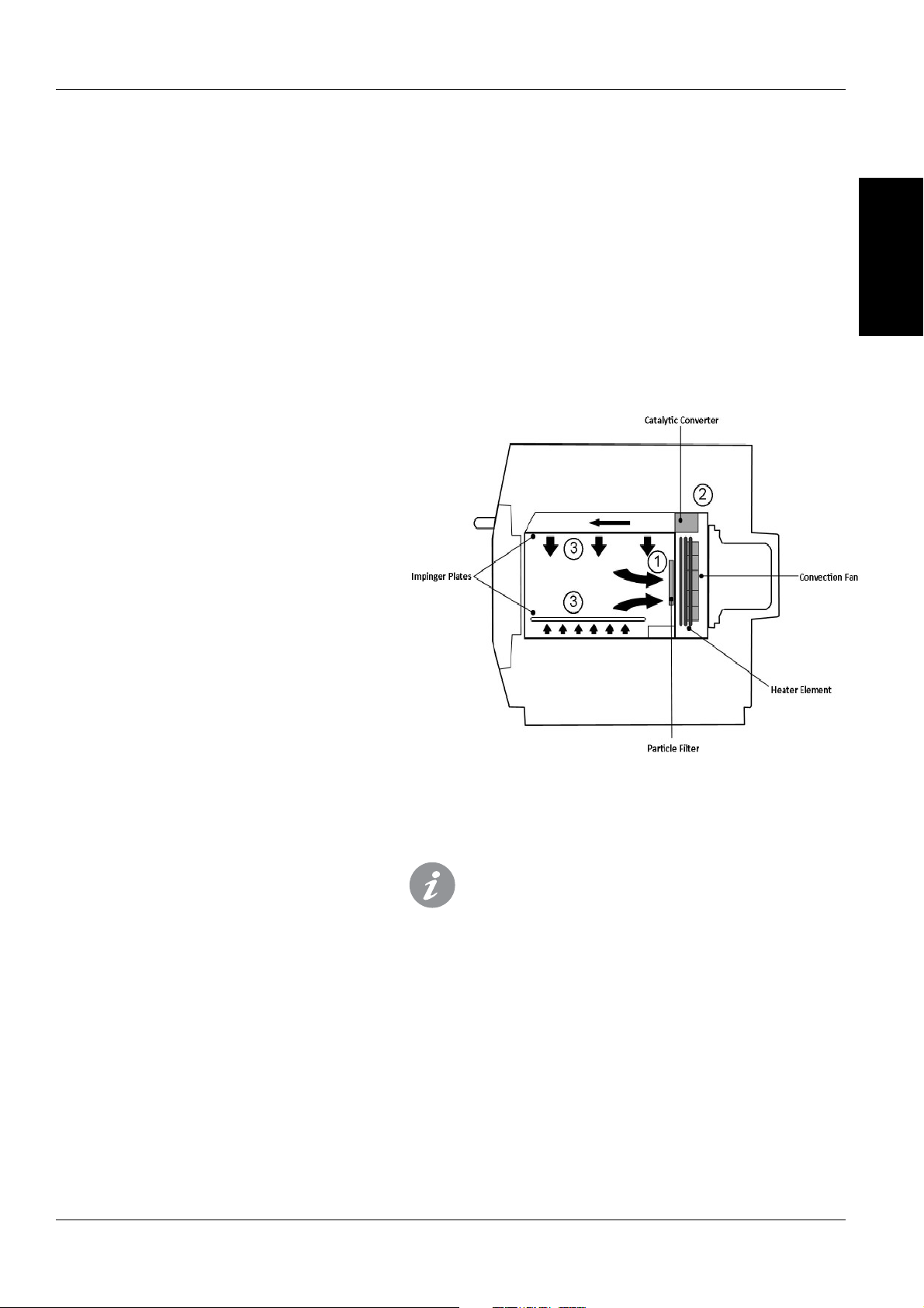
How it works:
The convection fan pulls air in through the Particle lter (1)
which removes the majority of particulates from the air ow.
The air is then heated and returned to the cavity through the catalyst
(2) and impinger plates (3) to produce an even heat pattern in the
oven. This heat layout minimises the areas where grease can build up,
allowing food to cook evenly to produce a crisp golden nish.
Start up Sequence
With the oven switch in the OFF position and the
mains power ON, the QTS & SRB boards boot up.
When the oven switch is turned ON the splash
screen brie y displays oven information and the
cabinet cooling fan is activated.
After completing a successful logic test, the safety
relay is energised and the oven preheats or displays
a preheat temperature choice. Once preheated the
oven displays the main menu if in FS mode or a
recipe selection if in QSR mode.
Shutting Down Sequence
When oven switch is turned OFF the screen displays
‘Shutting Down’ and the cooling fan operates until
the cabinet temperature has been su ciently
reduced (cavity temperature of 122F).
The safety relay is de-energised and the QTS & SRB
boards remain active.
6
Service & Parts Manual original Instructions
P
art Number 32Z3871 US
Issue 3
PRODUCT
DETAILS
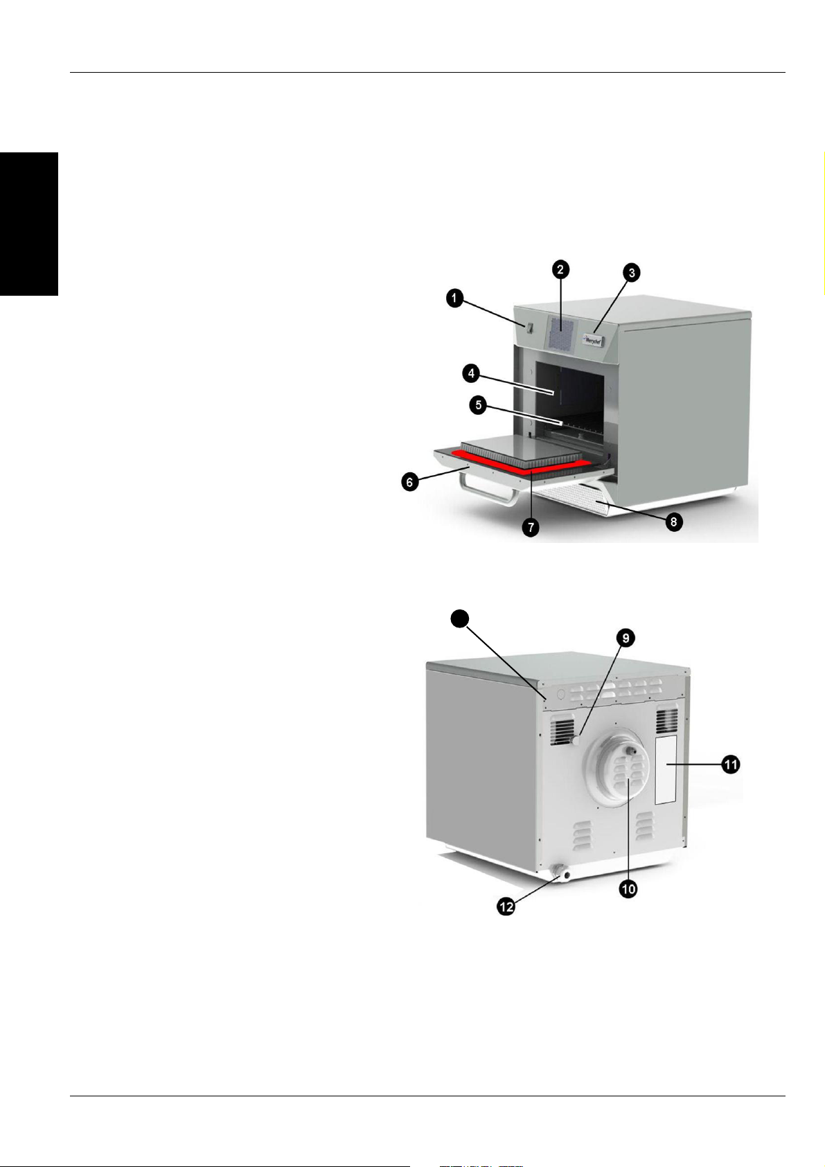
3 MAIN FEATURES
1 ON/OFF SWITCH
ON (I) activates the oven, OFF (0) switches the
oven to standby mode. IT DOES NOT ISOLATE
INTERNAL WIRING FROM THE MAINS SUPPLY.
2 CONTROL PANEL
Touch sensitive controls (easyToUCH) for
controlling oven functions, including diagnostics
and service mode.
3 USB menuKey
A socket
, located under the logo, allows a USB
menuKey to be used to update the cooking
programs and oven rmware on the pcb’s.
4 OVEN CAVITY
T
he oven cavity is mostly constructed from
stainless steel panels which must be kept clean
to avoid contamination of food products and
allow the oven to perform at peak e ciency.
5 IMPINGER PLATES (Upper & Lower)
Dir
ect the air in the cavity. They must be cleaned
on a regular basis, and kept free of debris.
6 OVEN DOOR
The twin-skinned door has a thermally insulated
inner section to lower the surface temperature
and incorporates a microwave choke.
7 DOOR SEAL
Provides a tight seal around the door and
must be kept clean. The seal must be checked
regularly and replaced if worn or damaged.
8 AIR FILTER
T
he air intake provides cooling air for internal
components and must be cleaned daily and
must NOT be obstructed. The lter must be in
place for the oven to function.
9 STEAM VENT
V
ents steam from the oven cavity.
10 HOT AIR FAN
Circulates hot air through the catalytic
convertors and oven cavity.
11 RATING PLATE
The rating plate, located on the rear oven cover,
states the Model, Serial Number, Electrical
Ratings and Manufacturers telephone number.
12 MAINS ELECTRIC POWER CABLE
Located on the rear of the oven and must be
replaced if worn or damaged.
13 OH STAT ACCESS BOLT
To reset cavity OH Stat remove bolt to gain
access to stat.
13
Service & Parts Manual original Instructions
Part Number 32Z3871 US
Issue 3
7
e4s
1024
<40/104
591x584x750
23.3x23.0x29.5
218x375x361
8.6x14.8x14.2
29.5 (1800)
1800
3.2
50 or 60
230 (50Hz), 208/240 or 220 (60Hz)
6.2
86.3 (190)
<60
750mm
29.5in
584mm
23.0in
591m
23.3in
643mm
25.3in
356mm
14.0in
PRODUCT
DETAILS
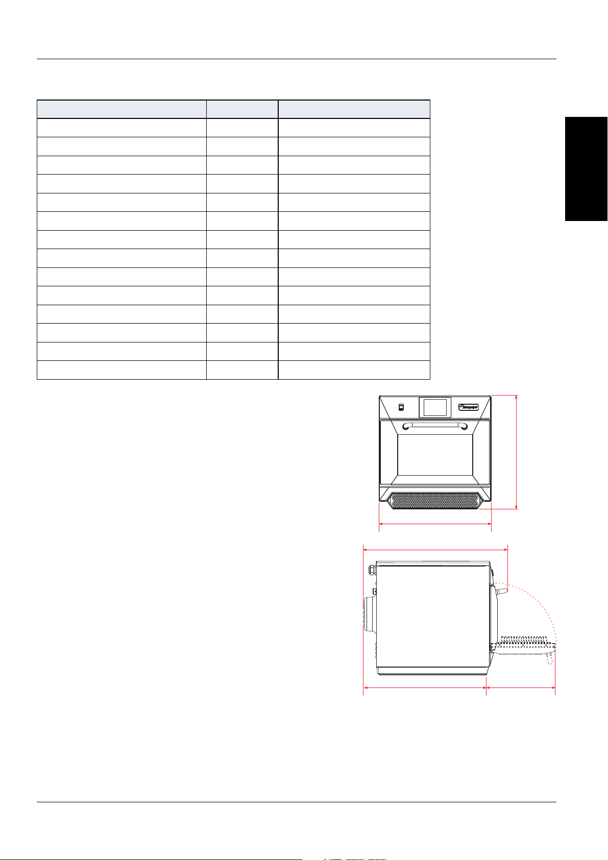
4 TECHNICAL SPECIFICATIONS
4.1 Speci cations
Description unit
Touch screen controls programs
Ambient operating temperature °C/°F
External HxWxD mm
External HxWxD inches
Internal HxWxD mm
Internal HxWxD inches
Cooking chamber Ltr (cu.ins)
Power output microwave Watts
Power output convection kW
Power supply Hz
Power supply V
Power supply kW
Unpackaged oven weight nett Kg (lbs)
Sound pressure level dB(A)
4.2 Serial Number (Rating Plate):
Serial number: YY MM SITE SERIAL
i.e. 10 06 2130 12345 (1006213012345)
Oven manufactured 2010 in June at She eld (UK),
production number 12345.
Model Number: MODEL CONVECTION MICROWAVE
VOLTAGE HERTZ LEAD PLUG COMMUNICATION
VERSION CUSTOMER/ACCESSORY COUNTRY
i.e. e4s S T MV 6 D F U 1 GM US
(e4sSTMV6DFU1GMUS)
model e4s, 3200W, 1800W, 208 or 240, 60Hz,
2P+GND (30A), Moulded NEMA 6-30P Plug, USB, 1,
General Market, USA.
8
Service & Parts Manual original Instructions
P
art Number 32Z3871 US
Issue 3
1
A A
A
B
PRODUCT
DETAILS
The oven will not operate without the AIR
FILTER correctly tted in place.
HANDLING & STORAGE:
When moving an oven always observe and follow
National and local requirements for lifting and
moving heavy objects. Do not use the oven door
handle to lift oven.
When not in use, electrically disconnect the oven
and store safely in a dry cool place, do not stack
ovens.
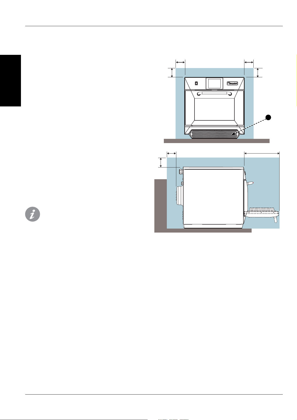
5 INSTALLATION
5.1 OVEN LOCATION AND POSITIONING
Choose a site away from major heat sources.
DO NOT position so that hot air is drawn in from
fryers, grills, griddles, etc.
A heat barrier to the height of the oven must be
installed if sited next to a burner, stove or range.
Place the oven on a permanent nonslip/
non ammable at surface that is LEVEL, STABLE and
STRONG enough for the oven and contents.
Allow a minimum clearance (A) of 2 inches (50mm)
around the oven for hot air to escape.
Allow su cient clearance (B), in front of the oven for
the door to open fully.
Position the oven at least 36 inches (916mm) (C)
above the oor.
The air intake is located at the lower front of the
oven (1) and it is important that the air ow is
as cool as possible and not preheated by other
appliances such as burners, stoves, ranges, fryers,
grills and griddles as this will deteriorate the life
and performance of the oven.
Do not a x labels/stickers to oven other than those
applied or approved by the manufacturer.

Service & Parts Manual original Instructions
Part Number 32Z3871 US
Issue 3
9
PRODUCT
DETAILS
DANGER!
THIS APPLIANCE MUST BE EARTHED.
FAILURE TO DO SO MAY RESULT IN
ELECTRIC SHOCK AND DEATH.
For all cord connected appliances:
GROUNDING INSTRUCTIONS
This appliance must be grounded. In the event of an
electrical short circuit, grounding reduces the risk of
electric shock by providing an escape wire for the electric
current. This appliance is equipped with a cord having
a grounding wire with a grounding plug. The plug must
be plugged into an outlet that is properly installed and
grounded.
WARNING - Improper use of the grounding can result in the
risk of electric shock.
Consult a quali ed electrician or Serviceman if the
grounding instructions are not completely understood
or if doubt exists as to whether the appliance is properly
grounded.
Do not use an extension cord. If the power supply cord is
too short, have a quali ed electrician or serviceman install
an outlet near the appliance.
For a permanently connected appliance:
GROUNDING INSTRUCTIONS
This appliance must be connected to a grounded, metallic,
permanent wiring system, or an equipment grounding
conductor should be run with the circuit conductors and
connected to the equipment grounding terminal or lead
on the appliance.
6 ELECTRICAL INSTALLATION
IN CASE OF RADIO OR TELEVISION INTERFERENCE
This equipment generates and uses radio frequency
energy and if not installed and operated correctly, in
strict accordance with the manufacturer’s instructions,
may cause harmful interference to authorized radio
communication services.
This product complies with the relevant requirements
of CFR 47 Ch.1 Part 18, which are designed to provide
reasonable protection against such interference. However,
there is no guarantee that interference will not occur in
a particular installation. If this equipment does cause
interference to radio or television reception, which can be
determined by turning the equipment o and on, the user
is encouraged to try and correct the interference by one or
more of the following measures:
1) Re-orientate the receiving antenna.
2) Relocate the microwave with respect to the receiver.
3) Plug the microwave into a di erent outlet so that the
receiver and microwave are on di erent branch circuits.
If necessary the user should consult the dealer or an
experienced radio/television technician for additional
suggestions.
Note: Modi cations should only be carried out by the
manufacturer or authorized representative to ensure
continuing conformance.
This device complies with Part 18 of the FCC rules.
POWER SUPPLY REQUIREMENTS
This appliance should be connected to a suitable
electricity supply which can cope with the switching
on surge that occurs with certain types of catering
equipment, including microwaves. Because of this
requirement, ,we strongly recommend that a separate,
suitably rated supply is installed for the oven.
The supply for the oven should be tted with a type “C” or
Time Delay circuit breaker rated at:
30 AMP for 208V electrical supply (2P+GND)
30 AMP for 240V electrical supply (2P+GND)
If the oven is hard wired to the supply, a double-pole
isolator switch with a contact gap of at least 1/8 inch
(3mm) should be tted.
10
Service & Parts Manual original Instructions
P
art Number 32Z3871 US
Issue 3
PRODUCT
DETAILS
2
1
3
4
5
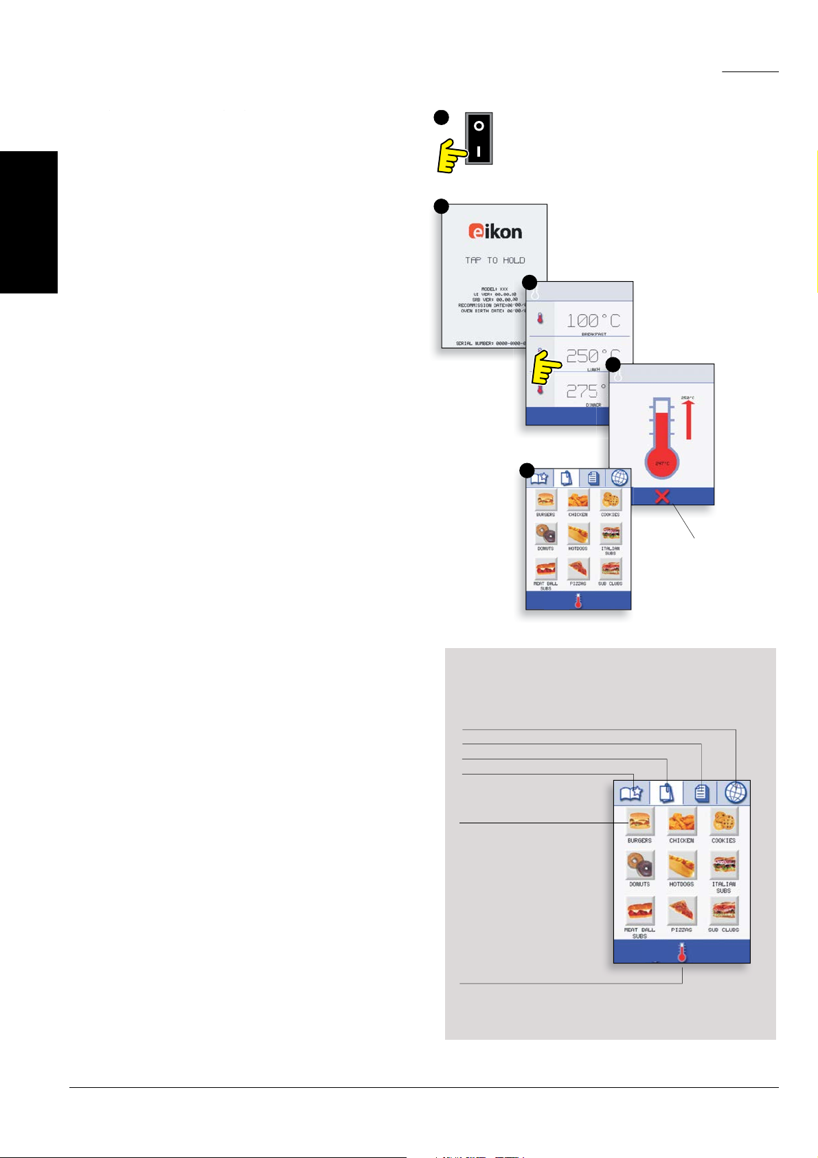
7.1 START UP
1. Switch the oven on;
Make all the relevant safety checks and ensure the
oven is clean and empty before pressing the oven
switch down to activate the oven.
2. The easyToUCH screen illuminates with the
display brie y showing the serial number and oven
data.If required, to keep the data on the screen,
Lightly tap the screen once to freeze the display, tap
again to continue.
3. When the oven is setup with two or more
preheating temperatures a choice is displayed.
Scroll arrows at the bottom of the screen indicates
there are more temperature choices not shown
on screen, if necessary, use the scroll arrows, then
select the temperature required to start preheating
the oven.
4. During preheating the display shows the progress
as the oven heats up to the set temperature. (To
stop the oven heating touch the red ‘X’ symbol.)
5. The oven is ready to use when the ‘COOKBOOK’ is
displayed.
STOP/CANCEL
The easyToUCH screen display, layout and icons
shown herein, are for guidance purposes only and are
not intended to be an exact representation of those
supplied with the oven.
MULTIPLE LANGUAGES INSTALLED
DISPLA
YS ALL COOKING PROGRAMS (Optional)
SHOWS PROGRAM GROUPS
FAVOURITES (Optional)
CHANGE OVEN TEMPERATURE (Optional)
PROGRAM GROUP
Each group contains a
collection of cooking
programs.
COOKBOOK DISPLAY
7 QUICK START GUIDE: QUICK SERVICE OVEN
Service & Parts Manual original Instructions
Part Number 32Z3871 US
Issue 3
11
PRODUCT
DETAILS
1
5
6
2
3
4
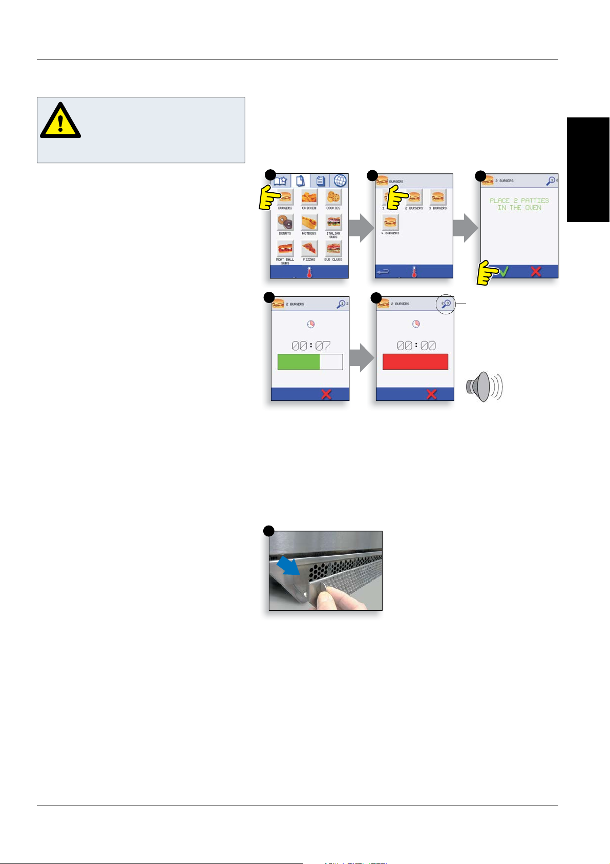
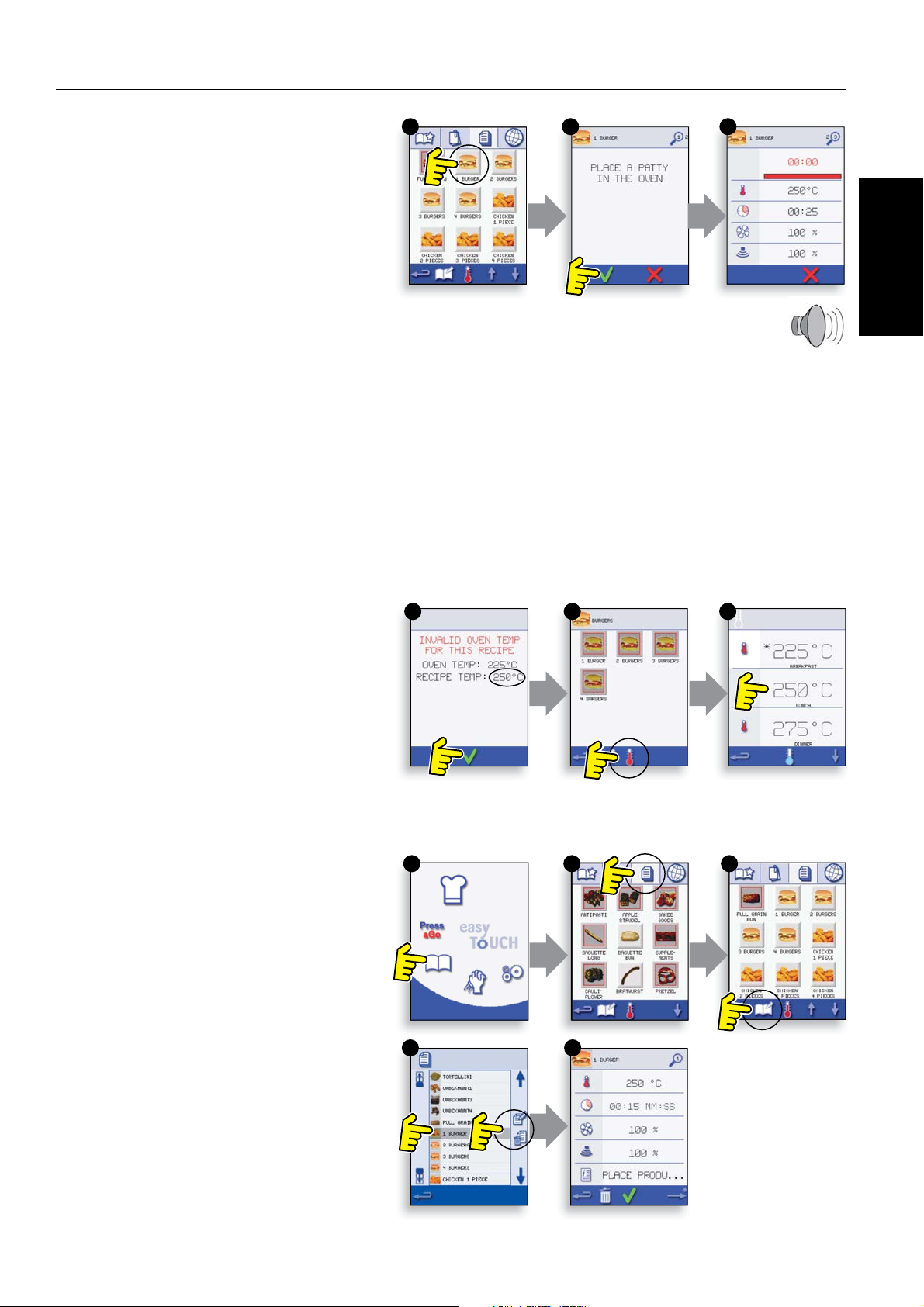
1. Select a program group, for example, ‘BURGERS’ to
displa
y the individual cooking programs.
2. Select a cook program to start, for example, 2
BURGERS.
3. Follow instructions if displayed on the screen.
4. Touch the green tick to cook.
The cooking time counts down for each program
stage.
5. When the program ends a red bar is displayed
usually with an audible sound - open the door or
touch the red ‘X’ to return to the cook program.
Note; opening the oven door during cooking stops the
cooking program and displays a warning. Closing the
door allows the user to continue or cancel the cooking
program.
Taking all the necessary
precautions to ensure you do not
burn yourself, open the oven door
to place the food into the hot oven
and close the door.
PROGRAM STAGE
7.2 USING A COOKING PROGRAM
AIR FILTER
IMPORTANT:
C
lean the AIR FILTER (6) in the base of the oven
every day and ensure that the air lter is in place
prior to operating the oven. See ‘CLEANING &
MAINTENANCE’.
12
Service & Parts Manual original Instructions
P
art Number 32Z3871 US
Issue 3
PRODUCT
DETAILS
1
2
3
4
5
6
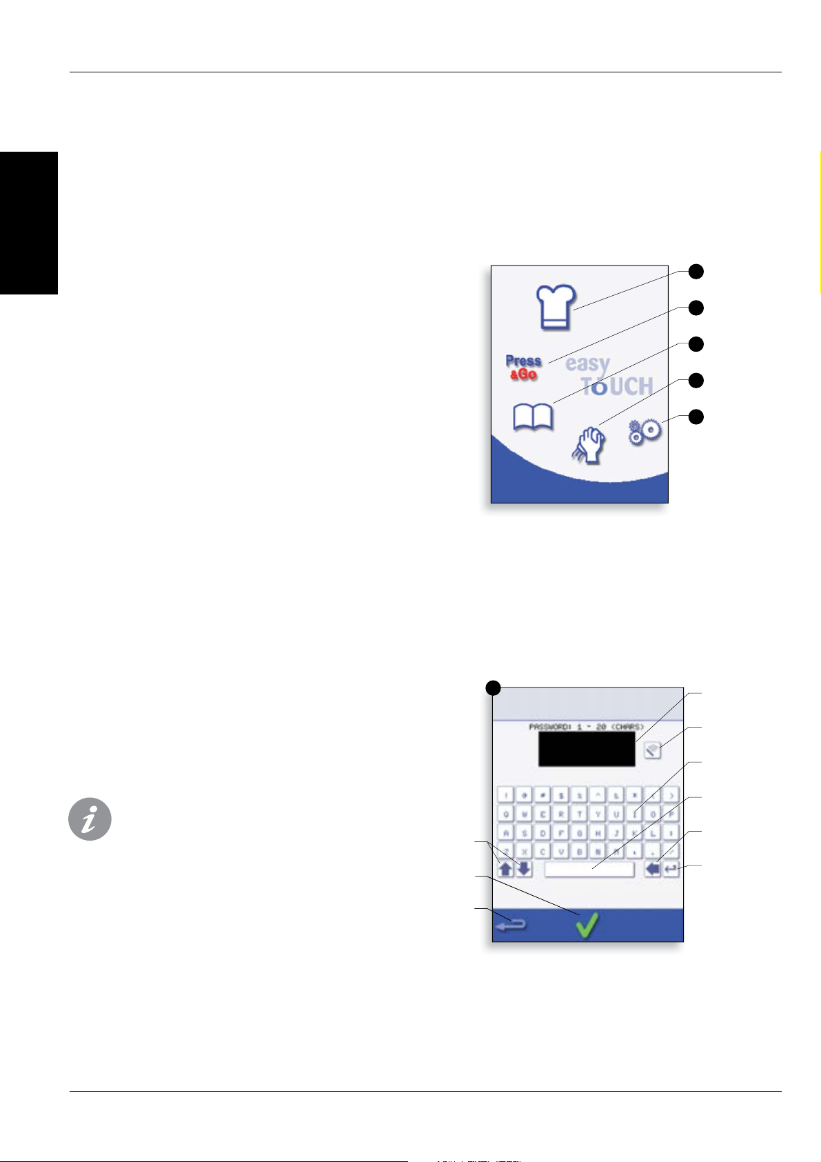
8.1 easyToUCH MAIN MENU &
KEY
BOARD SCREEN
MAIN MENU SCREEN:
1. DEVELOPMENT MODE enables multistage cooking
programs to be developed, then stored under a
name and symbol for reuse.
2. PRESS & GO allows quick access to use the
cooking programs that are already stored.
3. COOKBOOK contains the oven’s cooking
programs. It displays Favourites, Cooking Program
Groups and a complete listing of all cooking
programs available.
4. CLEANING/TEMP CHANGE allows the oven
temperature to be changed and the oven to be
prepared for cleaning with reminders displayed to
assist during the cleaning process.
5. SETTINGS are used to control the oven settings
and functions including time and language, loading
cooking programs and for service and maintenance
purposes.
6. KEYBOARD SCREEN is used to enter an authorised
password to enter data for programs and may
restrict operator access to some functions.
For Program Names, Program Group Names
and Passwords use 1-20 characters in 2 lines
max.
For Stage instructions use 1-54 characters in
5 lines max.
8 OPERATING GUIDE: FULL SERVICE OVEN
DEVELOPMENT
MODE
MENU
SHORTCUT
COOKBOOK
CLEANING/
TEMP CHANGE
SETTINGS
SCREEN
KEYBOARD
SCROLL
KEYBOARD
PREVIOUS
SCREEN
Backspace
CLEAR SCREEN
ENTER / OK
SPACEBAR
RETURN
Service & Parts Manual original Instructions
Part Number 32Z3871 US
Issue 3
13
PRODUCT
DETAILS
2
6
3
4
5
1
7
1
5
2
6
3
4
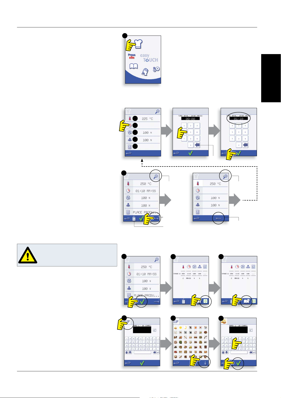
Running and saving the program
1. Select OK to con rm the Program.
2. Run the program (optional).
If the results are not satisfactory, select the
backspace, change the cooking settings and retest.
3. Select the save Cookbook symbol to record the
program to the cookbook.
4. Select the camera icon to open pictures.
5. Select a picture to represent the program. (Use
the scroll arrows for more pictures.)
6. Enter the name for the cooking program, using
a maximum of 20 characters, for example, ‘1
BURGER’, then select OK to save the program to the
Cookbook.
A green tick on a book indicates the program has been
saved to the Cookbook.
8.2 DEVELOPMENT MODE: CREATING A
COOK PROGRAM
1. Select the ‘chef’s hat’ symbol from the main menu
to enter development mode.
Enter stage 1 of the program
2. The temperature displays the set preheated oven
t
emperature.
To increase or decrease the temperature required,
select the temperature symbol (2), enter the
temperature in the keypad within the limits
displayed and select OK.
3. Select and set the cooking time up to a maximum
of 10 minutes for each stage.
For example : Enter 110 (1minute and 10 seconds).
4. Select and set the Microwave Power [0, 5-100%]
5. Select and set a Fan speed (if available) within the
limits shown on screen.
6. Select the information icon to enter an instruction
(Optional). The instruction appears in the display at
the beginning of that stage.
For example : ‘Stage 1 place product in the oven’.
Enter stage 2 of the program (Optional).
7. Programs can have up to a maximum of 6 stages.
R
epeat the steps 2-6 from stage 1 above.
WARNING: ENSURE PRODUCT IS IN THE
OVEN AND ALL SAFETY PRECAUTIONS
ARE FOLLOWED BEFORE RUNNING THE
PROGRAM.
Enter the cooking time
on the pad
.
Select OK to accept the
time.
To Set the cooking Time
select the Time symbol.
Example below; setting the cooking time (step 3):
STAGE 1
DISPLAYED
ADD STAGE
STAGE 2
DISPLAYED
BACK TO STAGE 1
CLEAR
DELETE STAGE
14
Service & Parts Manual original Instructions
P
art Number 32Z3871 US
Issue 3
PRODUCT
DETAILS
1
1
2
2
3
5
3
4
1 2 3
Change the
or
der of a
selected item
shown in the
Press & Go
screen.
Move a
selected item
to or from the
Press & Go
screen.
Select to scroll
a list up or
down.
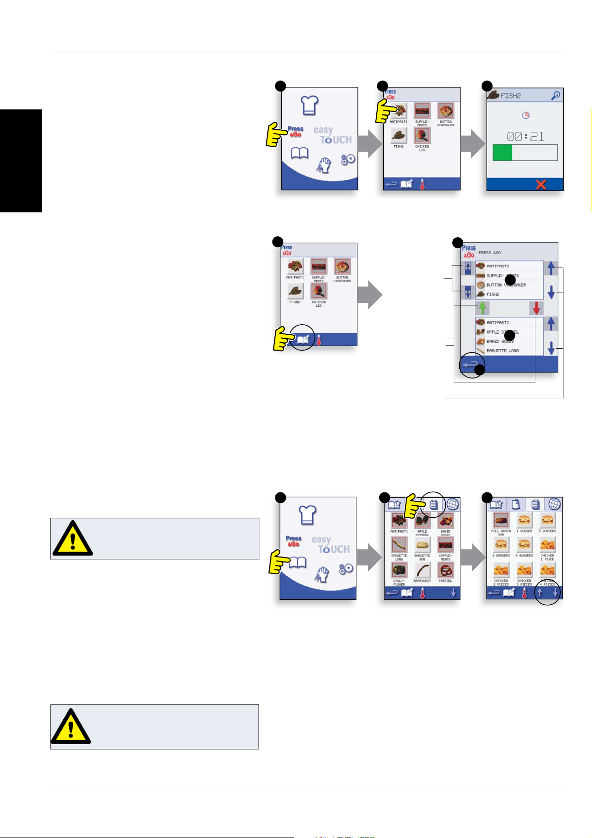
8.3 PRESS & GO
Running a c
ooking program from the Press &
Go menu.
1. Select ‘PRESS & GO’ from the main menu screen.
2. Select the item required to cook.
3. The display shows the cooking time count down.
The timer bar turns red to indicate the cooking cycle
has nished.
Choosing which cooking programs are shown in
the ‘PRESS & GO’ menu screen.
1. After selecting ‘PRESS & GO’ from the main menu
screen, select the EDIT symbol.
2. Two lists are displayed, the ‘PRESS & GO’ menu
items are shown in the upper list and the lower list
shows other menu items which are available. Both
lists can be scrolled up or down using the arrows on
the extreme right.
3. Select an item, then choose whether to change its
order within the menu or to remove it into the lower
list.
4. Select an item to move into the upper list, making
it available in the ‘PRESS & GO’ menu.
5. Select backspace to return to the menu screen
when nished.
WARNING: ENSURE THERE IS FOOD
PRODUCT IN THE OVEN BEFORE
STARTING A COOKING PROGRAM.
WARNING:
HOT SURFACE HAZARD
8.4 USING A COOKBOOK PROGRAM
T
o nd the required Program in the cookbook.
1. Select ‘COOKBOOK’ from the main menu screen.
2. Select the ALL MENUS symbol.
3. Use scroll up/down arrows to nd the program.
NOTE: if an image has a red line around it the oven
temperature is set too high or too low for that
recipe. See ‘CHANGING THE OVEN TEMPERATURE’.
Taking all the necessary precautions to ensure you
do not burn yourself, place the food product into
the hot oven cavity and close the door.
Service & Parts Manual original Instructions
Part Number 32Z3871 US
Issue 3
15
PRODUCT
DETAILS
1 2 3
5 64
1 2 3
4 5
8.5 CHANGING THE OVEN
TEMPER
ATURE
1. Take note of the temperature required for the
recipe and select OK.
2. Select the temperature symbol.
3. An asterisk next to the number indicates the
present oven temperature, select the required oven
temperature for the recipe. Once the oven is at the
required temperature continue from selecting the
‘COOKBOOK’ in step 1.
4. Select the required cooking program to start
cooking.
For example, ‘1 BURGER’.
5. The program either starts immediately displaying
a countdown timer, or an instruction is displayed
rst; follow the stage instruction then select OK to
start cooking. If the oven door is not opened within
30 seconds a warning message appears.
6. The cooking timer counts down to zero and
makes a sound to indicate an operator action is
required at the end of a cooking stage or the end of
a cooking program.
Once the cooking program has nished, opening
the oven door to remove the food returns the
display to the ‘COOKBOOK’ screen.
Note; opening the oven door during cooking stops the
cooking program and displays a warning. Closing the
door allows the user to continue or cancel the cooking
program.
To check the oven temperature when cooking, lightly
tap the temperature displayed, the oven cavity
temperature is shown with an asterisk.
8.6 VIEWING & EDITING PROGRAMS
1. Select ‘COOKBOOK’ from the main menu screen.
2. Select the ALL MENUS symbol.
3. Select ‘EDIT COOKBOOK’.
4. Use the up/down scroll arrows on the right side of
the screen to nd the cooking program, for example
1 BURGER and select the view/edit cooking program
symbol.
5. View or adjust the program as required, see
Development mode for details.
16
Service & Parts Manual original Instructions
P
art Number 32Z3871 US
Issue 3
PRODUCT
DETAILS
1 2 3
4
1
5
2
6
3
4
Scroll to show
pr
ograms in
the current
Program
Group
Move the
selected
program within
the Program
Group
Program Group
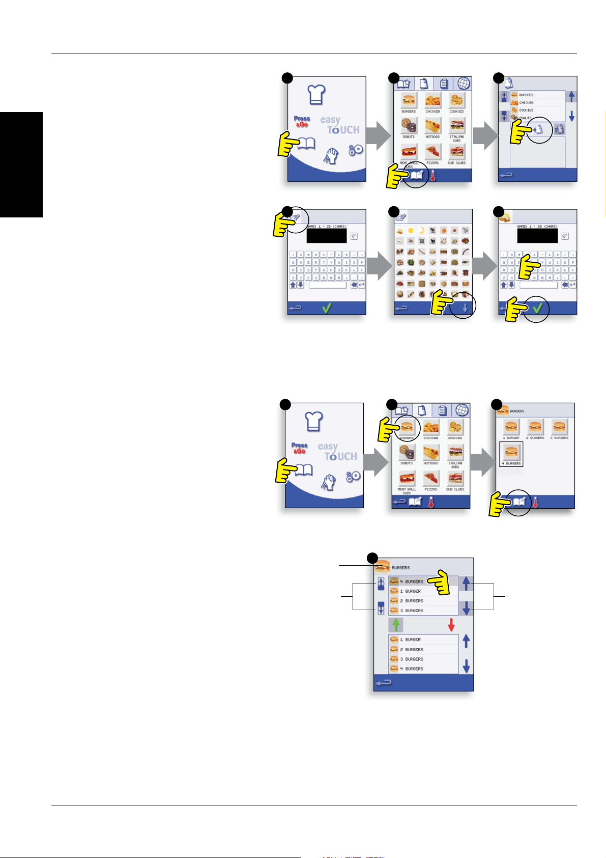
8.7 ADDING A NEW PROGRAM
GR
OUP
To add a new Program Group.
1. Select ‘COOKBOOK’ from the main menu
screen.
2. Select ‘EDIT COOKBOOK’.
3. Select the ‘ADD A NEW GROUP’ symbol.
4. Select the camera icon to open pictures.
5. Select a picture to represent the Group. (Use
the scroll arrows for more pictures.)
6. Enter a name for the new Program Group (max.
20 characters) and select OK to save the Program
Group to the Cookbook.
Select backspace to return to the ‘COOKBOOK’.
8.8 MOVE A PROGRAM WITHIN A
PROGRAM GROUP
Example moving the position of the ‘4 BURGERS’
cooking program within the program group called
‘BURGERS’.
1. Select ‘COOKBOOK’ from the main menu screen.
2. Select the ‘BURGERS’ program group.
3. Select ‘EDIT COOKBOOK’.
4. Use the up/down scroll arrows on the right side
of the upper part of the edit screen to view the
cooking programs in the group.
Then select the cooking program to be moved (‘4
BURGERS’) and use the up/down arrows on the
left side of the upper screen to move the selected
program within the program group.
Select backspace to return to the ‘COOKBOOK’
screen.
Service & Parts Manual original Instructions
Part Number 32Z3871 US
Issue 3
17
PRODUCT
DETAILS
1
5
2
34
1
5
2
6
3
4
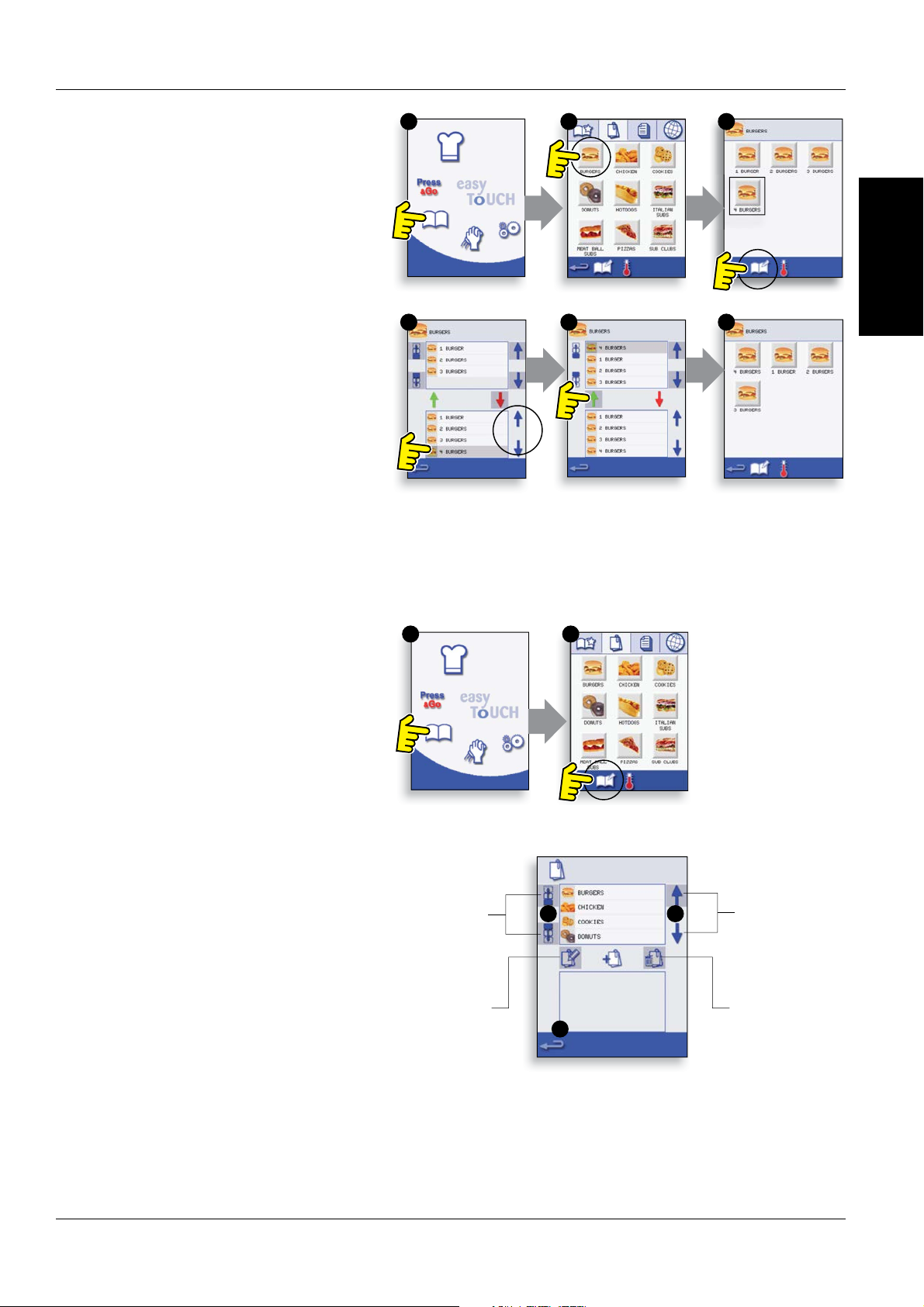
8.10 MANAGING PROGRAM GROUPS
To move a program position in a Program
G
roup
1. Select ‘COOKBOOK’ from the main menu screen.
2. S
elect ‘EDIT COOKBOOK’.
3. Use the scroll arrows, up and down on the right
side of the screen to locate all the Program Groups.
4. Select the Program Group to be moved and use
the up and down arrows, on the left side of the
screen to move the selected program.
5. Select backspace to go back to the ‘COOKBOOK’.
To change the Program Group name.
Select the Program Group.
Select EDIT PROGRAM GROUP.
Enter the new name and select OK.
To delete a Program Group
Select the Program Group.
Select the DELETE Program Group symbol.
Select OK to Delete the Group.
Scroll to show
Program
Groups
Move the
selected
Program
Group
Edit the
selected
Program
Group name
Delete the
selected
Program Group
8.9 ADDING A PROGRAM TO A GROUP
To add a cooking program to an existing
PROGR
AM GROUP.
Example add Program ‘4 BURGERS’ to the program
group ‘BURGERS’.
1. Select ‘COOKBOOK’ from the main menu screen.
2. Select the ‘BURGERS’ Program Group.
3. Select ‘EDIT COOKBOOK’.
4. In the lower part of the screen use the up/down
scroll arrows on the right side to nd and select the
‘4 BURGERS’ cooking program.
5. Select the green UP arrow to add the ‘4 BURGERS’
cooking program to the Program Group in the
upper part of the screen, then select backspace to
return to the cooking programs.
6. Select backspace again to return to the
‘COOKBOOK’.
18
Service & Parts Manual original Instructions
P
art Number 32Z3871 US
Issue 3
PRODUCT
DETAILS
A
B
C
D
1 2
D
G
K
A B
E
C
F
J
M
H
L
3 4
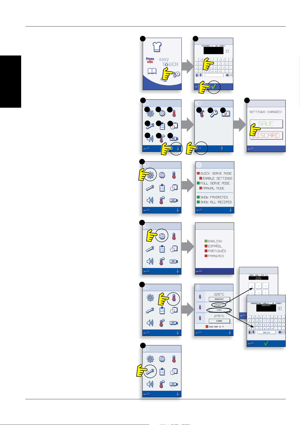
1. Select the ‘settings’ symbol from the main menu
screen.
2. Enter the password and select OK to display the
Settings menu (3) comprising:
A. Oven mode/navigation settings.
B. Language options.
C. Oven temperature settings and labels.
D. Service information and error logs (password
required).
E. Recipe counters.
F. Date & time settings.
G. Speaker sound levels.
H. Oven Timer (Temperature/ON/OFF).
J. USB program connection.
K. Temperature Band.
L. Change Settings/Service access passwords.
M. Screen saver.
When nished with a setting, select backspace to
return to the main settings menu.
To exit the settings menu, select backspace,
a prompt will be displayed to either ‘SAVE’ or
‘DISCARD’ any changed settings (4).
9 OVEN CONTROL SETTINGS
9.1 Oven mode/navigation settings (A)
9.1.1 Select the oven mode/navigation symbol (A)
from the ‘Settings’ menu.
9.1.2 Select ‘Quick Serve Mode’ for cooking only,
or ‘Full Serve Mode’ for cooking & development
programs or ‘Manual mode’ to manually cook only via
the ‘Chef hat’ symbol.
9.1.3 Select ‘Enable Settings’ to display an ‘unlock’
symbol on the Quick Serve Cookbook screen to allow
access to the ‘Settings’ menu.
9.2 Language options (B)
9.2.1 Select the globe symbol (B).
9.2.2 Select the checkbox of the required language
from the list shown.
9.3 Oven temperature settings and
labels (C)
9.3.1 To change the oven preheat temperature, select
the temperature symbol (C) to display the keypad,
enter the required temperature and select OK.
9.3.2 Note, the temperature options screen is only
displayed at start up when two or more temperatures
are set above minimum.
9.3.3 To change a temperature label, select the label
to display the keyboard, enter the required label name
and select OK.
For Service information & error logs (D) refer
to Servicing.
 Loading...