

Merrychef Evolution Service Manual

Page 1
CAUTION MICROWAVE EMISSIONS
DO NOT BECOME EXPOSED TO EMISSIONS FROM THE MICROWAVE
GENERATOR OR PARTS CONDUCTING MICROWAVE ENERGY
SERVICE MANUAL
Evolution
SERVICE MANUAL
For all Evolution models manufactured f r om January 2001
Part No. 32Z3382e Issue No. 3

Page 2
Table of Contents
Safety Code ................................................................3
Product Specifications ................................................4
Dimensions. Location and Installation ........................5
Manual RHS controls .................................................. 7
Error Codes and Diagnostics ...................................... 8
Main Features ............................................................ 9
A -Power Output Testing to EN 60335-2-90:1996 ..... 10
B - Power Output Testing ..........................................11
C - Power Transformer Test .....................................11
D - High Voltage Capacitor Test ............................... 12
E - High Voltage Rectifier Test .................................. 12
Principal Components: Right side view ..................... 13
Principal Components: Right side view ..................... 14
Principal Components: Rear view, top view ..............15
Oven Door Assembly ................................................ 16
Door Interlock Operation ........................................... 17
Error Light Operation ............................................... 17
Input Wiring Details ................................................... 18
Control Panel Assembly ............................................19
Membrane Panel Circuit ............................................ 20
Circuit Diagram .................................................21 & 22
Parts Matrix ............................................................... 23
Reply Form ............................................................... 24
Merrychef Limited,
Station Road West,
Ash Vale,
Aldershot, Hampshire GU12 5XA,UK.
Tel: +44 (0)1252 371000 Fax: +44 (0)1252 371007
Internet address: http://www.merrychef.co.uk
E-mail: sales@merrychef.co.uk
or
service@merrychef.co.uk

Page 3
This manual is designed to assist engineers who have been on a recognised product familiarisation
and training course run by Merrychef Limited. It has been prepared to off er tec hnical guidance f or the
Merrychef Evolution range of Combination Microwave Ovens.
Please remember that it is wiser
not
to attempt a service task if you are unsure of being able to
complete it competently, quickly, and above all
safely
.
To avoid injury to yourself, and to protect the appliance from possible damage, please follow this
Safety Code when servicing these ovens.
Before attempting to repair the oven, check it for microwave leakage.
Check that the oven is not emitting microwaves, even when supposedly not in operation.
Check that the oven is not operating continuously, whether the display indicates cooking
or not.
Always discharge the HT capacitors before working on the oven using a suitably insulated
10 MΩ Resistor
Before removing the rear cover from the oven, do all
of the following:
•
Switch off the mains supply and remove the plug from the wall socket.
or
•
If the oven is hard wired, ensure that the power is turned off at the isolator switch.
Note:
The On/Off switch on the oven is
not
adequate protection against electric shock , as it does
not isolate all of the internal wiring from the mains.
Upon completion of a service on a Evolution oven, or before r econnecting the appliance to the m ains
supply for testing, check all
of the following points:
•
All internal electrical connections are correct.
•
All wiring insulation is correct and is not touching a sharp edge.
•
All Earth connections are electrically and mechanically secure.
•
All four door safety interlocks are secure and mechanically sound.
•
The door operation is smooth, and the arms run freely in the slots.
•
The door activates all four of the door interlock switches
in the correct order
.
•
All fuse-holder safety covers are correctly fitted.
•
The temperature sensor is correctly connected to the Power PCB.
Before finishing the service call, recheck the following points:
•
All of the electronics are functioning correctly, and all of the touch pads are working
•
The turntable is rotating freely
•
The power output of the oven is correct
•
Microwave emission is below permissible limit - 5 mW/cm² (see BS EN 60335-2-90:1998)
•
Oven has correct 120 mm air gap all round and 100 mm above. Air flow should not be
restricted
SAFETY CODE

Page 4
Model Number: EV + Voltage + Frequency + Phase + Version
Power Output
Microwave 100%
Convection Heat
Combination
2000 Watts (IEC 705 Rating) Single & Twin supply
1800 Watts (IEC 705 Rating) Three Phase supply
5000 Watts
2000 Watts Microwave + 5000 Watts Convection Heat
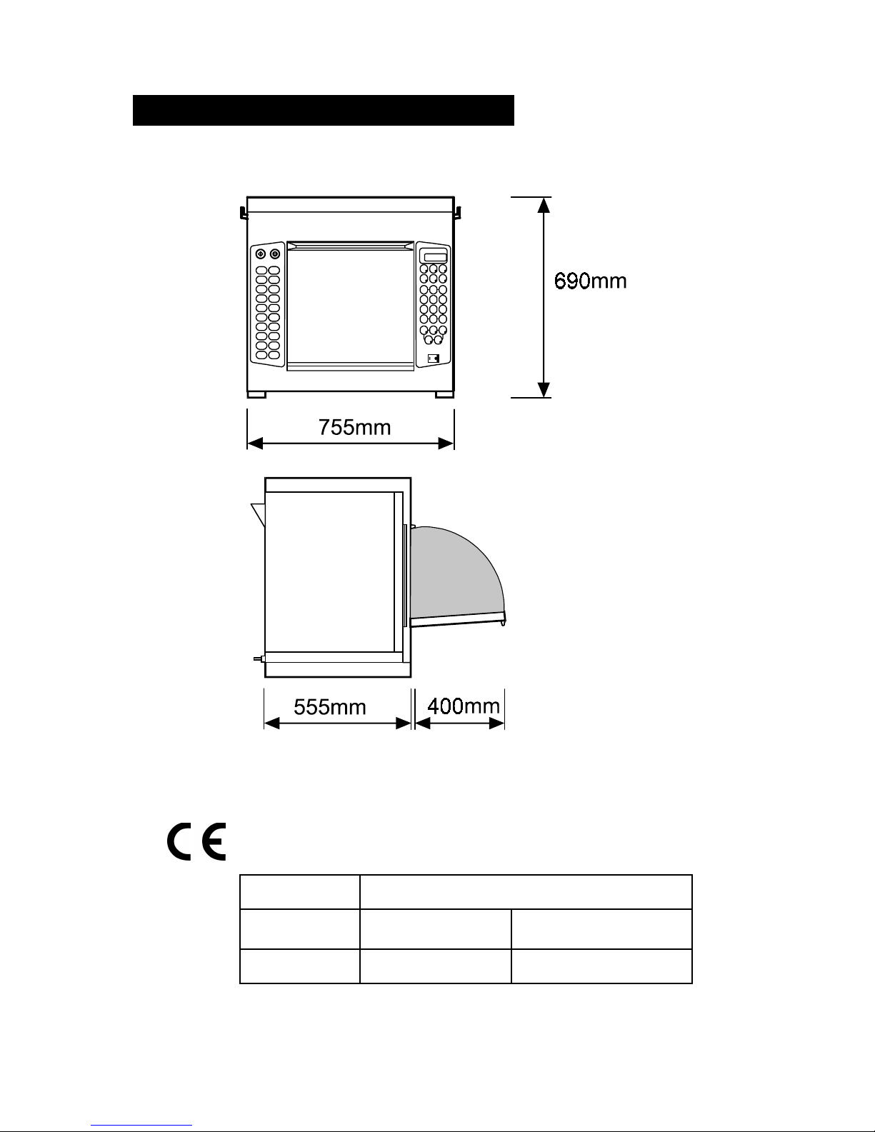
External
Dimensions
Height
Width
Depth
700 mm (Plus 100 mm minimum clearance above = 800 )
755 mm (Plus 100 mm minimum clearance each side = 955 )
555 mm (Plus 100 mm clearance behind = 655 )
Internal
Dimensions
Height
Width
Depth
Turntable
Capacity
315 mm
330 mm
330 mm
300 mm Diameter
34.3 litres (1.21 ft³)
Weight
Net
Gross packed
82 kg
90 kg
Construction
Cavity
Casework
304 Stainless Steel
304 Stainless Steel
Settings
Microwave
Temperature
Timer
100%,75%,50%,25%, Convection only
Off, 150°, 200°, 250°, 275°,300°C
Up to 30 minutes (Manual)
3 cooking stages of up to 30 minutes each (Programed)
Control System
Wipe-clean touch pad operating microprocessor based control system
Single touch control of temperature
Direct readout of time, power and temperature set
Digital readout of cavity temperature available
100 Pre-programmed cooking sequences
Built-in diagnostic messages
Safety
Features
Four door interlock switches
Cavity Overheat Sensor
Magnetron Overheat Sensor
Blocked Air Filter Sensor
Automatic Lock-out on invalid time setting
Convection Fan and Heater disabled when door open
Additional
Features
•
Easy-to-use multistage programming
•
Manual and Pre-programmed mode always available
•
Rapid cavity pre-heat
•
Low-loss insulated cavity and door
•
One-touch selection of temperature
•
Magnetron soft-start circuit for increased life and faster activation
PRODUCT SPECIFICATIONS
Power Requirement Voltage Current Microwave Convection Combination
Single EV2451B
240V 45A 20A 21A 41A
P1 240V 25A 20A 1A 20A
P2 240V 25A 0 20A 20A
Twin EV2452B
Model prefix Voltage Frequency Phase Control Type
24=240V 5 = 50 Hz
6 = 60 Hz
1 = Single
2 = Twin
3= Three Phase
B
EV
Page 5
DIMENSIONS AND LOCATION
A sample of this product has been tes ted and found to be in conformity
with the following directives:
Directive
EMC 89/336 EEC EN 55011
EN 50082-1
1991 (Emissions)
1992 (Immunity)
LVD 73/23 EEC EN 60 335-2-90
Harmonised standards applied.

Page 6
Power Supply Requirements
The Evolution should be connected to a suitable electricity supply, which can cope with the
switching-on surge that occurs with certain types of catering equipment, such as microwaves.
Because of this requirement, we strongly recommend that a separate, suitably rated supply is
installed for the oven.
The supply for the oven should be fitted with a
Type "C"
circuit breaker. Please ref er to rating
plate for details.
If the oven is hard wired to the supply a double-pole isolator switch with a contact gap of at least
3mm should be fitted.
Positioning the Oven
In order to maintain adequate ventilation for air intake and exhaust, and to allow access for
cleaning filters, you must allow a minimum of 100 mm clearance at the sides and 100 at the rear
of the oven, and at least 100 mm above. Air intake temperature should not exceed 35°C excessive temperature can lead to reduced operating duty cycle or premature ageing of internal
components.
NEVER
Install an oven above fryers, grills, griddles or any other major heat source.
NEVER
Stack machines on top of each other - always use a double stand.
INSTALLATION INSTRUCTIONS
Page 7
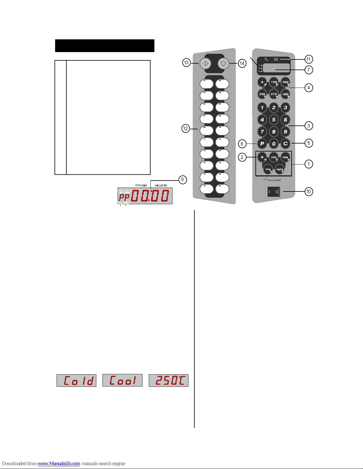
MANUAL CONTROLS
below 100ºC
100C-125ºC
above 125ºC
1 POWER PADS
2 CONVECTION PAD
3 TIME/PROGRAM SELECT PADS
4 TEMPERATURE SETTING PADS
5 CANCEL PAD
6 PROGRAM PAD
7 TIME AND PROGRAM DISPLAY
8 MULTI-STAGE INDICATOR
9 COLON
10 ON/OFF SWITCH
11 ERROR DISPLAY
7 TIME AND
PROGRAM
DISPLAY
1. POWER PADS
There are 4 Microwave Power Pads to select from:
25%, 50%, 75%, and 100%. A light will indicate the
one in use.
2. CONVECTION PAD
This is used when foods only require browning( no
microwave)
Note: when cooking the MICROWAVE and
CONVECTION pads start the cycle and timer. You
may alter power levels during a manual cooking cycle.
When cooking is interrupted, a light will flash as a
reminder that the time is being held (see PAUSE).
3. TIME/PROGRAM SELECT PADS
These pads are used for setting the cooking time in 1
second steps to a maximum of 30 minutes.
They are also used for programs from 21-99.
4. TEMPERATURE SETTING PADS
These pads are used to set the convection
temperature. A light will indicate the temperature set.
Selecting the ‘0’ key will switch convection off. If a
temperature key is pressed and held the current oven
temperature will be displayed in the time display
window.
5. CANCEL/ CALLBACK ‘C’ PAD
Cancels all timed cooking cycles, pre-programmed
operations and stop the microwave energy. It does not
alter the oven temperature . If the oven is hot food will
continue to cook and should be removed from the oven
immediately. This pad will also cancel any incorrect
operations. It will not erase programs. It can also be
used to view the details of stored programs.
(see CALL BACK)
6. PROGRAM ‘P’ PAD
Activate or set program
7. TIME AND PROGRAM DISPLAY
Shows the time set in minutes and seconds and counts down
in 1 second steps during a cooking cycle.
Also displays error messages and oven temperature.
(PROBLEM SOLVING section 8)
The program display indicates the program number
selected. ‘PP’ indicates programming
8. MULTI-STAGE INDICATOR
Indicates stage in multi-stage cooking
9. COLON
W hen programming the colon will flash to indicate the
time may now be entered.
10. ON/OFF SWITCH
11. ERROR DISPLAY See PROBLEM SOLVING Section 8.
12. QUICK ACCESS PADS
For programs 01-20
13. START
Starts a quick access program
14. STOP
Stops a quick access program
PHUU\
FKHI
Page 8
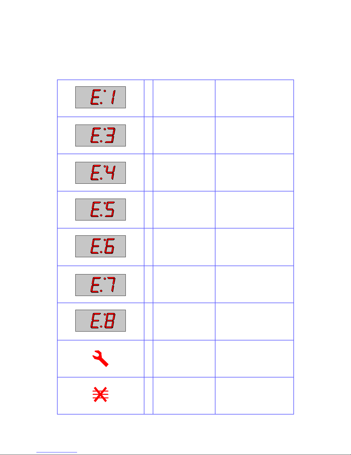
Error Codes and Diagnostics
The Evolution will identify some of the most common problem s by flashing an error m es sage code in
the time display window. (See also Error Light Operation page 17).
These are the error messages and suggestions for repairing them.
1
2
Door not fully shut.
Possible electrical fault
Close door fully.
Door switch inoperative.
1
2
3
No time has been set.
Invalid time has been set.
Invalid program has been
set.
Set a time.
Set a valid time.
Use call-back to check program.
1
2
3
Oven not heating up.
Possible Heater fault.
Possible Sensor fault.
Check heater fuse.
Confirm operation of heater circuit.
(RS units) Check slave heater relay and second supply.
1
Oven Cavity overheating.
Confirm heater relay is operating.
(RS units) Check slave heater re-
lay .
1
Oven is not at correct temperature to start program.
Remove food.
Allow oven to reach correct temperature.
Operator Error !!
1 Left Hand
Magnetron overheating.
Check air filters.
Check location, air inlet temperature and air filters.
Note : this will lead to condition
shown below. See Page 18
1 Right Hand
Magnetron overheating
Check air filters.
Check location, air inlet temperature and air filters.
Note : this will lead to condition
shown below. See Page 18
1
2
Magnetron has overheated but has now recovered.
Internal diagnostic fault
Check that magnetron cooling fan
and turntable are working correctly.
Check installation, air inlet temperature and air filters.
See Page 18
1
Oven control area is overheating.
Check air filters.
Check axial fan.
Check installation for hot air intake.
 Loading...