

Merlin Gerin Sepam 20, Sepam 40 Quick Start Quide
03146790FE+G0+NP00000000
Electrical network protection
59607
Series 20/advanced UMI/24-250V
Séries 20/IHM avancée/24-250V
59607
Test PASS: 12/14/2006
Operator: C99
S10UD
Final testing:
date and
operator code
Sepam series 20
Sepam series 40
PE50465
DANGER
HAZARD OF ELECTRIC SHOCK, BURN
OR EXPLOSION
b turn off all power supplying the Sepam
and the equipment in which it is installed
before working on it.
b always use a proprely rated voltage
sensing device to confim that power is off.
b replace all devices, doors, and covers
before turning on power to this equip ment.
b before energizi ng the power equipment,
replace all barriers and covers.
Failure to observe this instruction will
result in death, serious injury or
equipment damage.
Quick start
Storage
Sepam may be stored in its original packaging in a closed
sheltered location :
b ambient temperature: -25 °C ... +70 °C (or -13 °F ... +160 °F)
b relative humidity y 90 %.
Periodic checking of the storage environment and of the packaging
on a yearly basis is recommended.
Commissioning
Once installed, the Sepam must be energ ized as soon as possible,
especially in a damp location (humidity u 90 %).
Storing an unenergized and unpackaged Sepam f or a long period
may damage the unit.
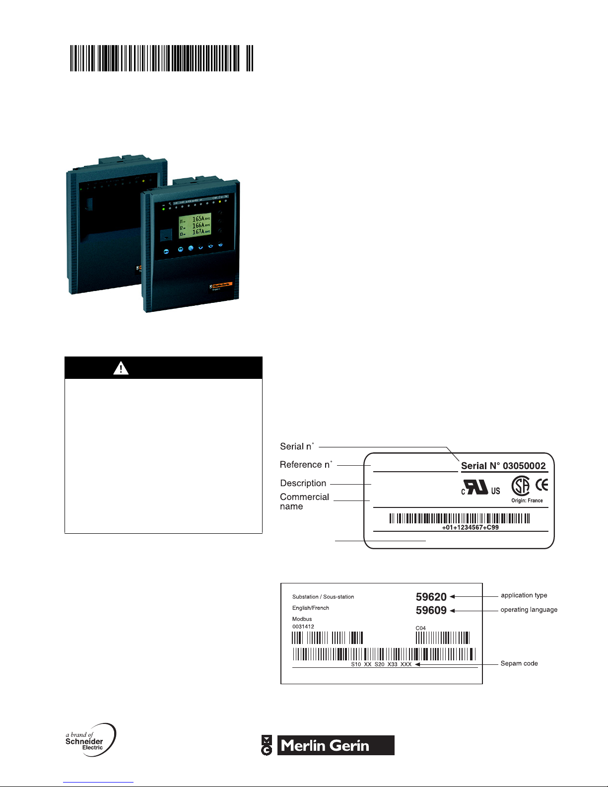
Identification
Each Sepam comes in a single package that contains the base
unit and its connector.
Other optional accessories such as modules, current or voltage
input connectors and cables come in separate packages.
To identify a Sepam, check the 2 labels on the right side panel of
the base unit that describe the firmware and hardware fe atures of
the product:
b hardware equipment label (for instance Sepam series 20)
DE80191
For more informations, please refer to "Sepam series 20
Installation and user’s manual" PCRED301005EN or
"Sepam series 40 Installation and user’s manual"
PCRED301006EN.
b firmware equipment label
DE80197
Installation Safety instructions
Important notes Safety symbols and messages
Restricted liability
Electrical equipment should be serviced and
maintained only by qualified personnel.
No responsibility is assumed by Schneider
Electric for any consequences arising out of the
use of this manual. This document is not
intended as an instruction manual for untrained
persons.
Device operation
The user is responsible for checking that the
rated characteristics of the device are suitable for
its application. The user is responsible for
reading and following the device’s operating and
installation instructions before attempting to
commission or maintain it. Failure to follow these
instructions can affect device operation and
constitute a hazard for people and property.
Read these instructions carefully and look at the equipment to
become familiar with the device before trying to install, operate,
service or maintain it. The following special messages may
appear throughout this bulletin or on the equipment to warn of
potential hazards or to call atte ntion to informati on that clarifies or
simplifies a procedure.
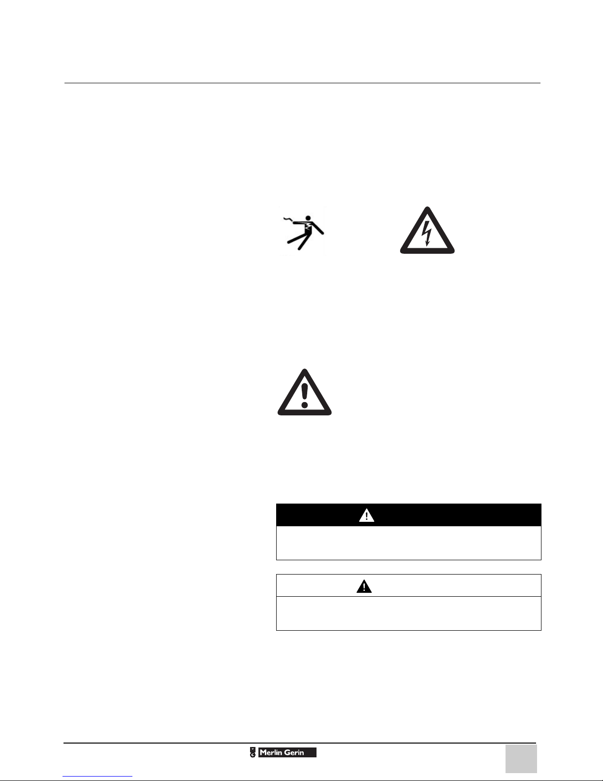
Risk of electric shock
ANSI symbol. IEC symbol.
The addition of either symbol to a “Danger” or “Warning” safety
label on a device indicates that an electrical hazard exists, which
will result in death or personal injury if the instructions are not
followed.
Protective grounding
The user is responsible for compliance with all
the existing international and national electrical
codes concerning protective grounding of any
device.
Safety alert
This is the safety alert symbol. It is used to aler t yo u to pote n tia l
personal injury hazards and prompt you to consult the manual.
Obey all safety instructions that follow this symbol in the manual
to avoid possible injury or death.
Safety messages
DANGER
DANGER indicates an imminently hazardous situ ation
which, if not avoided, will result in death, serious injury or
property damage.
CAUTION
CAUTION indicates a potentially hazar dous situation which,
if not avoided, could result in minor or moderate injury or
property damage.
03146790FE-G0 03/2007
2
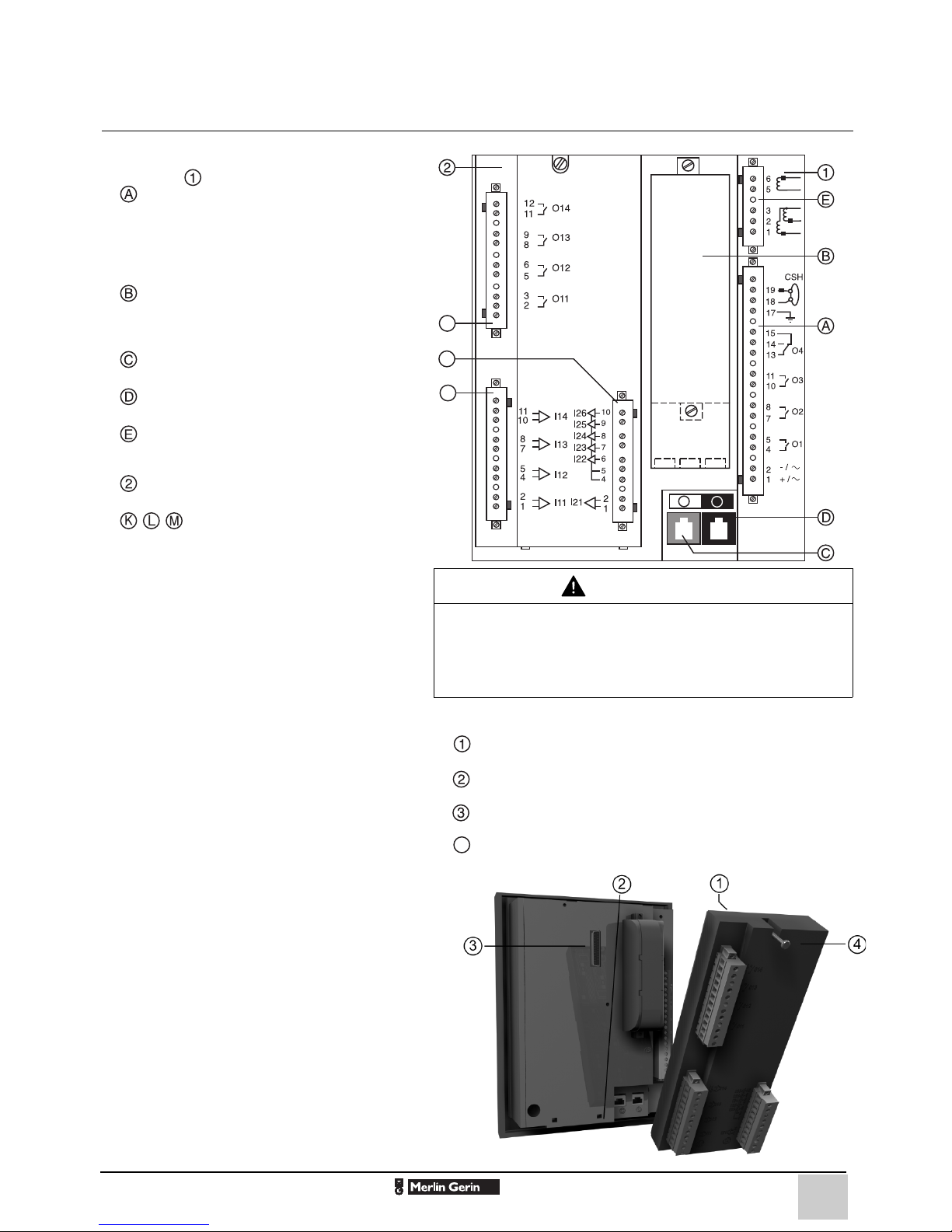
Installation Connection
L
K
M
D
C
4
Sepam components
b Base unit
v base unit connector:
- 24-250 V DC, 110-220 V AC power supply
-output relay
- input CSH30 / CSH120 / CSH200 / ACE990.
Screw type connector (CCA620) represented, or
ring lug connector (CCA622).
v 1 A/5 A CT input current connector
(CCA630 / CCA634), or LPCT input current
connector (CCA670), or voltage input connector
(CCT640 series 20 only)
v communication module link connection
(white)
v remote inter-module link connection
(black)
v input voltage connector (series 40 only):
screw-type connector (CCA626) represented or
ring lug connector (CCA627).
b optional input/output modules
(MES114)
v MES114 module connectors
Connections
Base unit
The Sepam connections are made to the
removable connectors located on the rear of the
device.
All the connectors are screw-lockable.
Wiring of screw connectors:
b without fitting:
v maximum 1 wire cross-section: 0.2 ... 2.5 mm²
(AWG 24-12) or 2 wires with maximum crosssection: 0.2 ... 1 mm² (AWG 24-18)
v stripped length: 8 to 10 mm (0.31 ... 0.39 in)
b with fitting:
v wiring recommended with fitting
Telemecanique:
- DZ5-CE015D for 1 wire: 1.5 mm² (AWG 16)
- DZ5-CE025D for 1 wire: 2.5 mm² (AWG 12)
- AZ5-DE010D for 2 wires: 1 mm² (2 x AWG 18)
v tube length: 8.2 mm (0.32 in)
v stripped length: 8 mm (0.31 in).
Wiring of CCA622 and CCA627 connectors
b ring lug or spade lug 1/4" (6.35 mm)
b maximum wire cross-section: 0.2 to 2.5 mm²
AWG 24-12)
(
b stripped length 6 mm (0.236 in)
b using a suitable crimping tool, crimp lugs onto
wires
b insert no more than 2 ring lugs or spade lugs
under washers
b torque 0.7 to 1 N•m (6 to 9 lb-in).
Wiring of CCA630 and CCA634 connectors
b ring lug or spade lug 0.16 in (4 mm)
b maximum wire cross-section of 1.5 to 6 mm²
(AWG 16-10)
b torque 1.2 N•m (11 l b- i n ) .
DE80214
CAUTION
HAZARD OF IMPROPER OPERATION
Do not use a CCA634 and residual current input I0 on
connector A (terminals 18 and 19).
Failure to follow this instruction can cause equipment
damage.
Installation of the optional MES114 module
b set MES114E and MES114F selector switch on VDC or
VAC
b insert the 2 pins on the MES114 module into the slots of the
base unit
b push the module up against the unit to plug it into the
connector
b tighten the mounting screw
PE80064
03146790FE-G0 03/2007
3
 Loading...