

Page 1

www.mgeups.com
MGE UPS SYSTEMS
Pulsar Evolution
2200/3000/3000 XL
Installation and user
manual
English
Français
Deutsch
Italiano
Español
Nederlands
W
O
N
U
O
Y
P
O
T
S
L
L
I
W
G
N
I
H
T
O
N
3400711500/AA
Page 2
www.mgeups.com
MGE UPS SYSTEMS
Pulsar Evolution
2200/3000/3000 XL
Installation and user
manual
W
O
N
U
O
Y
P
O
T
S
L
L
I
W
G
N
I
H
T
O
N
34007115EN/AA - Page 1
Page 3

Page 2 - 34007115EN/AA
Page 4

Introduction
Thank you for selecting an MGE UPS SYSTEMS product to protect your electrical equipment.
The Pulsar Evolution range has been designed with the utmost care. We recommend that you take the time to read this
manual to take full advantage of the many features of your UPS.
MGE UPS SYSTEMS pays great attention to the environmental impact of its products. Measures that have made Pulsar
Evolution a reference in environmental protection include:
◗ the eco-design approach used in product development,
◗ recycling of Pulsar Evolution at the end of its service life.
To discover the entire range of MGE UPS SYSTEMS products and the options available for the Pulsar Evolution range,
we invite you to visit our web site at www.mgeups.com or contact your MGE UPS SYSTEMS representative.
34007115EN/AA - Page 3
Page 5
Foreword
Using this document
Information may be found in two ways, using:
◗ the contents;
◗ the index.
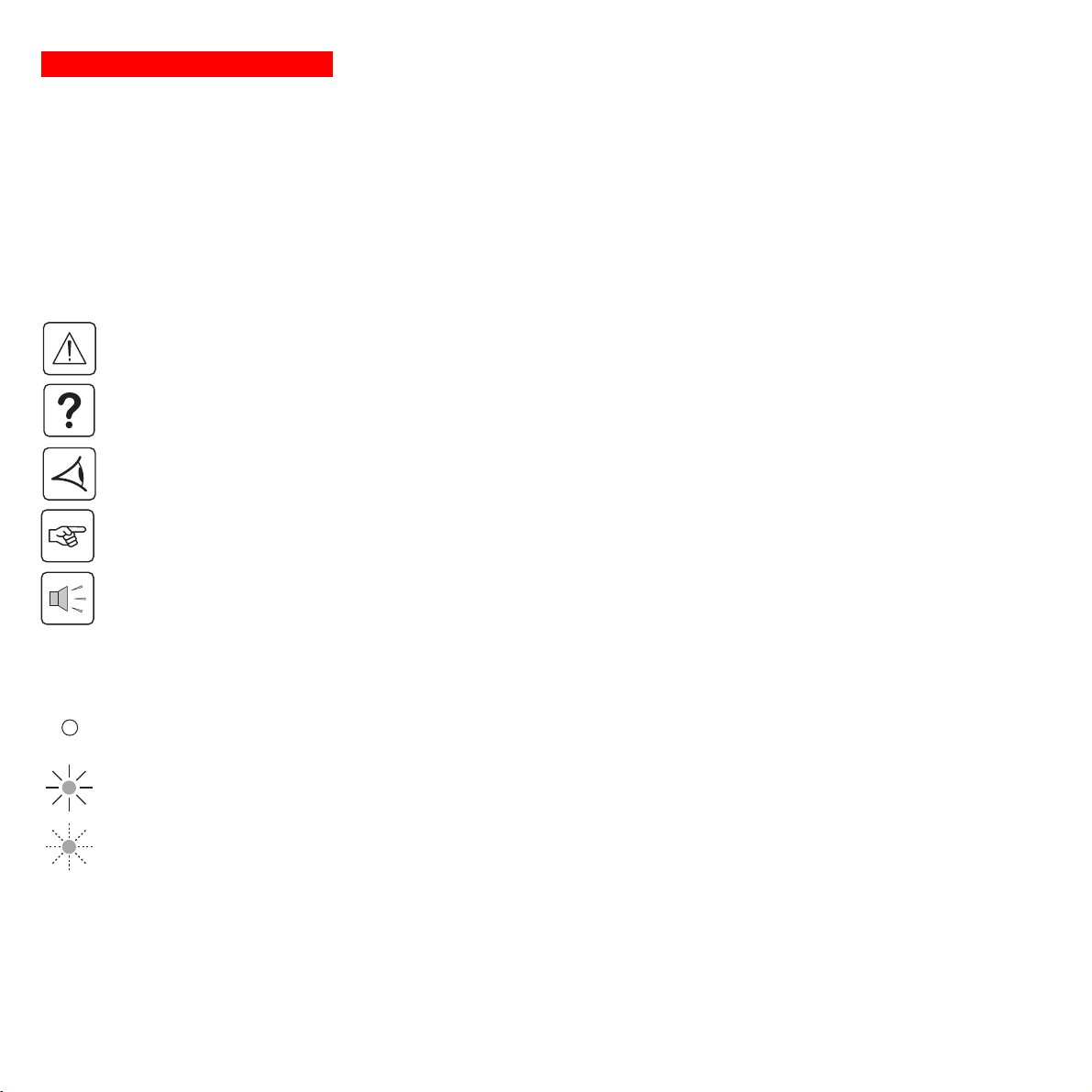
Pictograms
Important instructions that must always be followed.
Information, advice, help.
Visual indication.
Action.
Audio indication.
Page 4 - 34007115EN/AA
In the illustrations on the following pages, the symbols below are used:
LED off.
LED on.
LED flashing.
Page 6

Contents
1. Presentation
1.1 Overall view ................................................................................................................................. 7
Tower position ................................................................................................................................. 7
Rack position .................................................................................................................................. 7
1.2 Back ............................................................................................................................................. 8
1.3 Control panel ................................................................................................................................. 9
2. Installation
2.1 Unpacking and parts check ....................................................................................................... 10
2.2 Upright installation (tower position) ......................................................................................... 11
2.3 Flat installation (rack position) .................................................................................................. 12
2.4 Connecting the protected equipment ....................................................................................... 13
2.5 Connection to the RS232 or USB communications port (optional)......................................... 14
2.6 Connection to the data-line protection port (optional) ............................................................. 14
2.7 Installation of the communications-card option ...................................................................... 15
3. Operation
3.1 Start-up ........................................................................................................................................ 16
3.2 Shift to booster or fader mode (during voltage variations in the AC-input power)..................... 16
3.3 Operation on battery power (following failure of AC-input power) ............................................. 17
Transfer to battery power .............................................................................................................. 17
Threshold for the low-battery warning...........................................................................................17
3.4 Personalisation (optional) ........................................................................................................... 18
Function ........................................................................................................................................ 18
ON / OFF conditions tab ............................................................................................................... 18
Battery tab..................................................................................................................................... 18
Voltage-thresholds tab .................................................................................................................. 19
Sensitivity tab ................................................................................................................................ 19
4. Maintenance
4.1 Trouble-shooting......................................................................................................................... 20
4.2 Replacement of the battery module .......................................................................................... 21
5. Environment ..................................................................................................................................... 23
34007115EN/AA - Page 5
Page 7

Contents
6. Appendices
6.1 Technical data ............................................................................................................................. 24
Simplified diagram ........................................................................................................................ 24
Technical characteristics ............................................................................................................... 25
Examples of battery backup times ................................................................................................26
6.2 Glossary....................................................................................................................................... 27
6.3 Index............................................................................................................................................. 28
Page 6 - 34007115EN/AA
Page 8
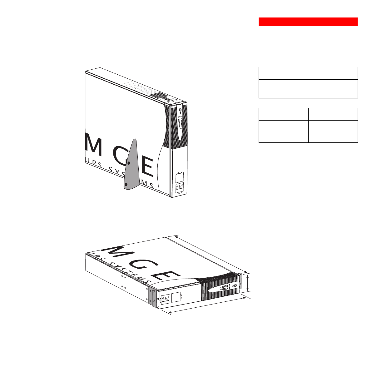
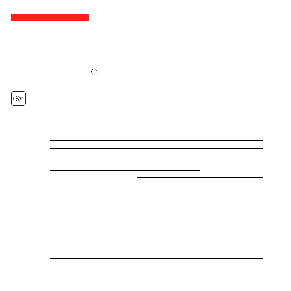
1.1 Overall view
Tower position
1. Presentation
Dimensions in mm
(W x H x D)
Evolution 2200
Evolution 3000
Evolution 3000 XL
438 x 87.9 x 640
(19") (2U)
Weight in kg
Rack position
P U L S A R
Evolution
3 0 0 0
P U L S A R
Evolution
3 0 0 0
Evolution 2200
Evolution 3000
Evolution 3000 XL
34
37
21
D
H
W
34007115EN/AA - Page 7
Page 9
1. Presentation
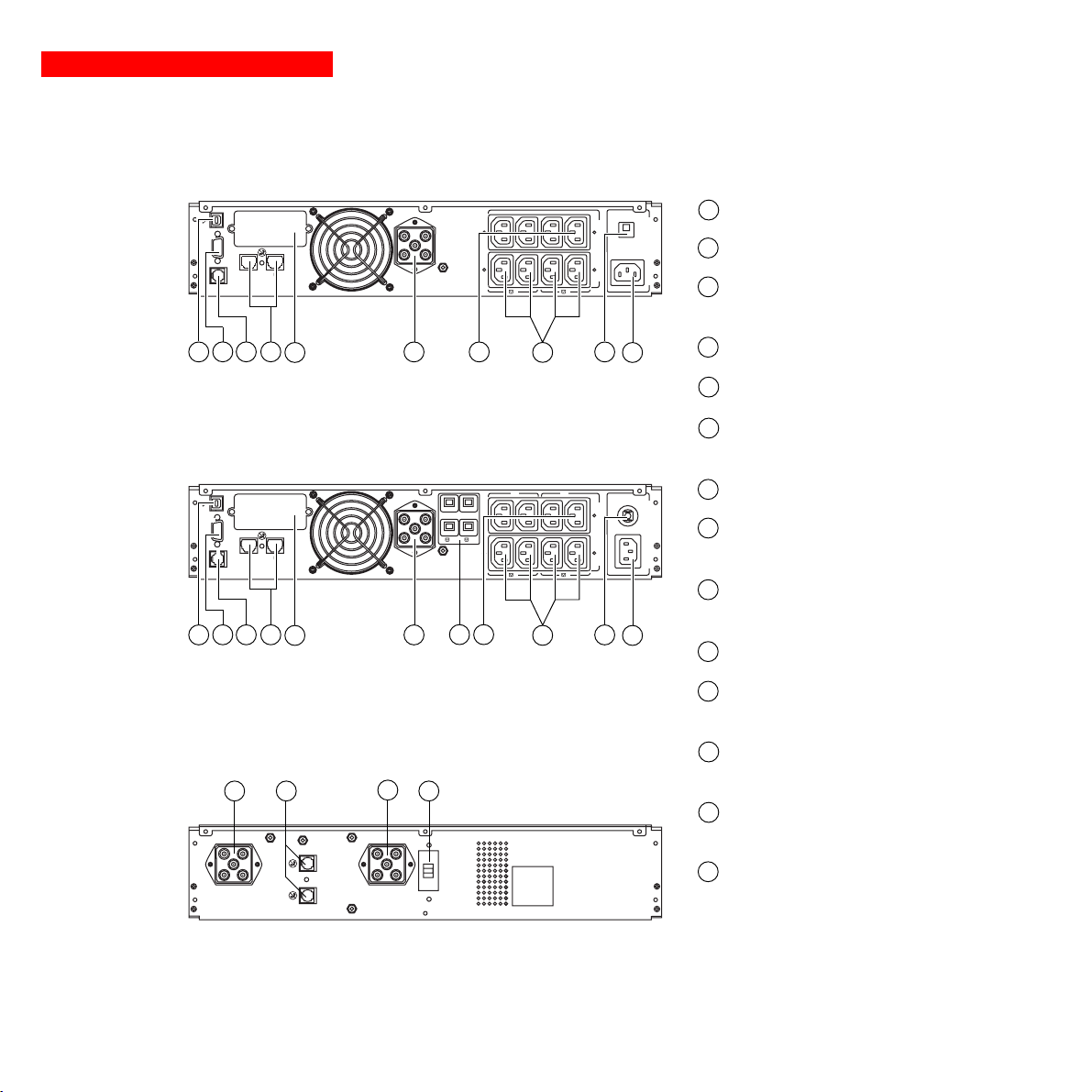
1.2 Back
Pulsar Evolution 2200
RS232
DATA LINE PROTECTION
IN OUT
TO BATTERY
CABINET
1 234 115 1098
Pulsar Evolution 3000 / 3000 XL
RS232
DATA LINE PROTECTION
IN OUT
TO BATTERY
CABINET
1 234 115 109
USB communications port.
1
2
RS232 communications port.
Us/Out/Ausg I max 10A
Ue/In/Eing 230V/10A Max
3
1 2
2
1
6
Connector for automatic detection of an
additional battery module.
4
Data-line protection.
5
Slot for communications-card option.
6
Connector for an additional battery
module.
Ue/In/Eing 230V/16A Max
7
Output circuit breakers.
8
Four outlets for direct connection of
protected equipment.
9
Two groups of two programmable
AB
1
2
AB
1 2
2
1
Us/Out/Ausg I max 13A
outlets (groups 1 and 2).
8
7
6
10
Input circuit-breaker.
Page 8 - 34007115EN/AA
EXB additional battery module
12 14
13
12
11
Socket for connection to AC-power
source.
12
Battery module connectors (to the UPS
or to other battery modules).
13
Connectors for automatic detection of
additional battery modules.
14
Circuit breaker for battery ON/OFF and
protection.
Page 10
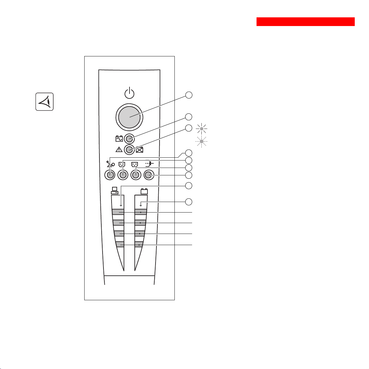
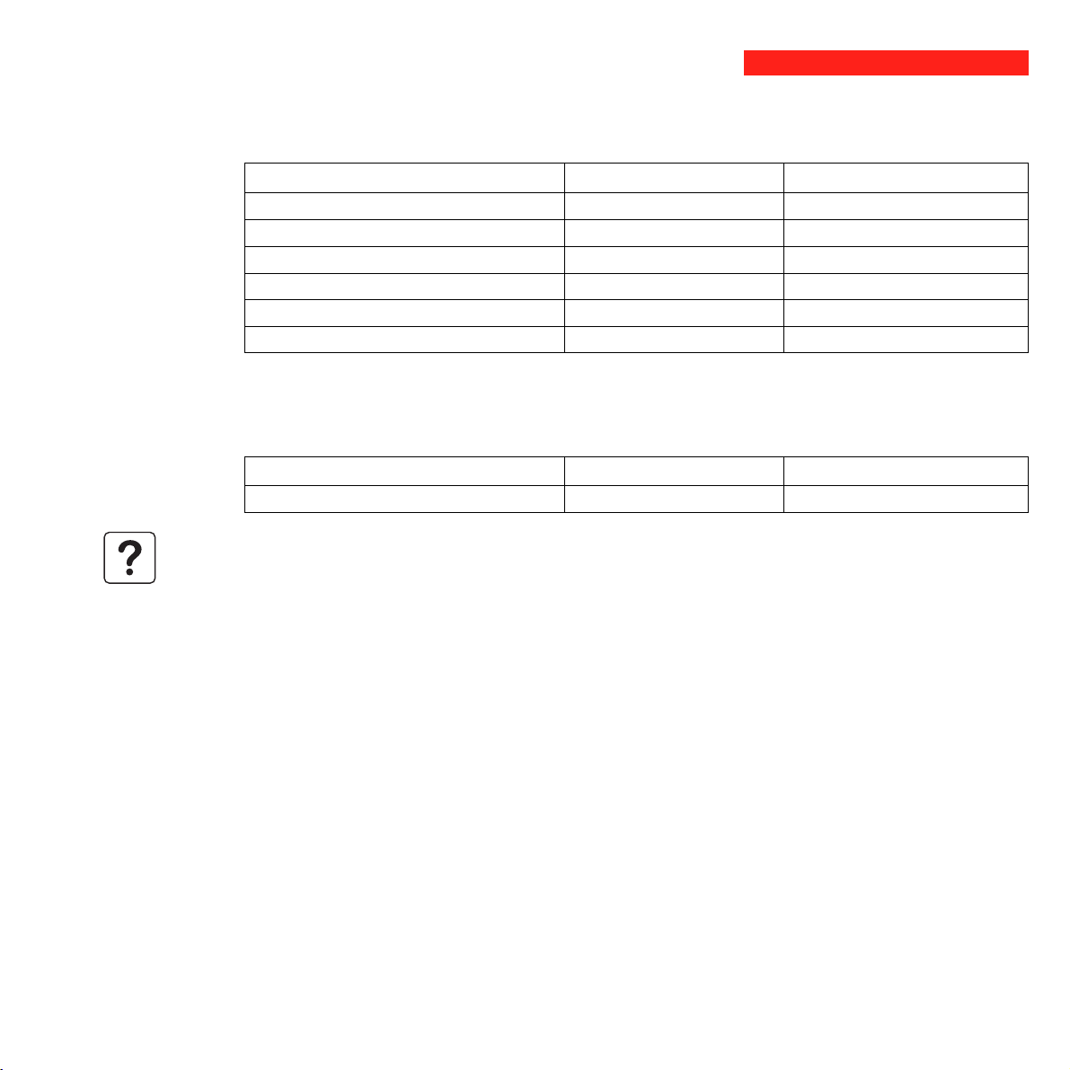
1.3 Control panel
15
Iluminated ON/OFF button for the outlets.
16
Operation on battery power.
1. Presentation
17
UPS fault.
Battery fault.
Overload.
18
Group 1 programmable outlets supplied with power.
1
2
%
%
19
Group 2 programmable outlets supplied with power.
20
21
Booster or fader mode.
22
Bargraph indicating percent load at output.
23
Bargraph indicating the battery charge level.
76 to 100%.
51 to 75%.
26 to 50%.
0 to 25%.
34007115EN/AA - Page 9
Page 11
2. Installation
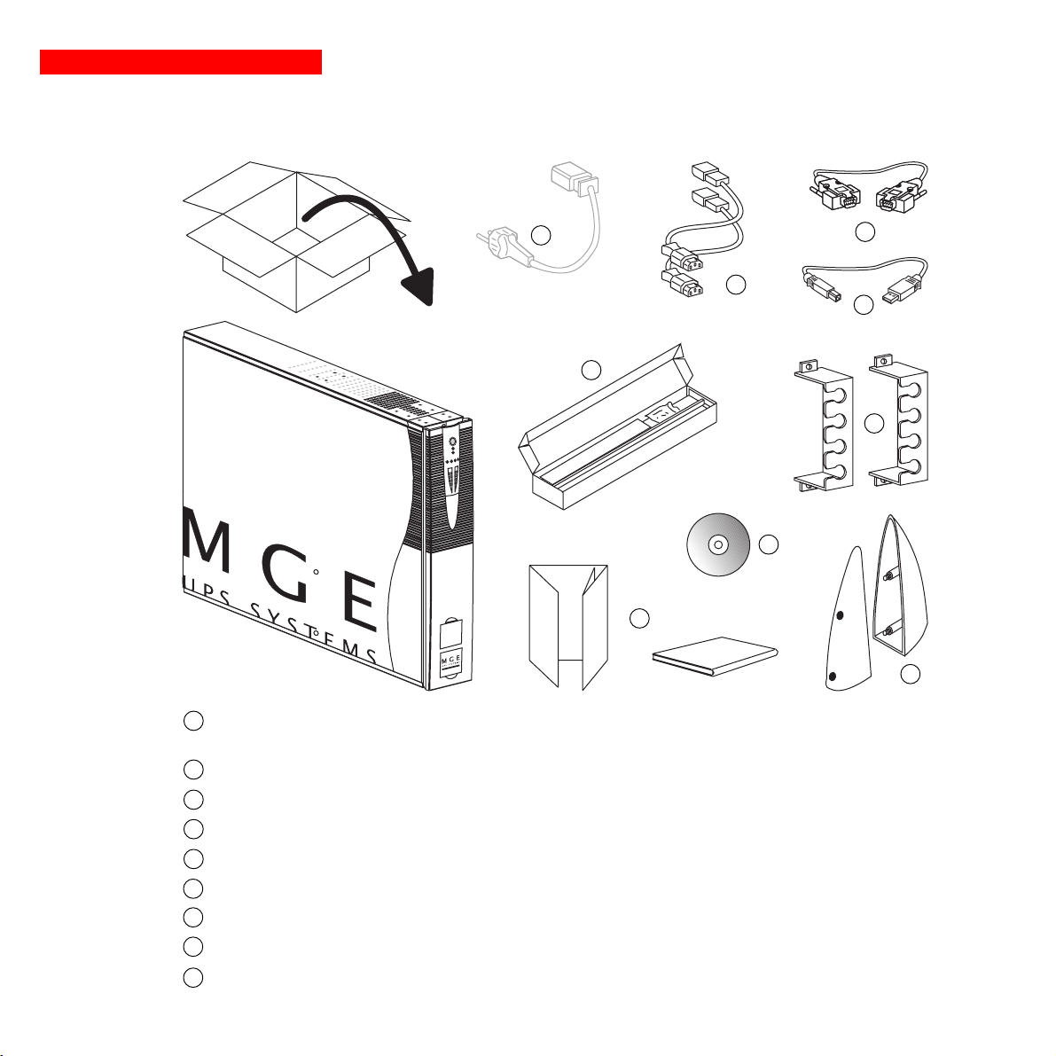
2.1 Unpacking and parts check
24
26
25
27
28
29
30
P U L S A R
Evolution
3 0 0 0
31
32
24
Cord for connection to the AC-power source for 3000/3000 XL versions only (for the 2200 version, use the power cord
of the protected equipment).
25
Two cords for connection of the protected equipment.
RS232 communications cable.
26
27
USB communications cable.
Telescopic rails for mounting in 19" bay with mounting hardware.
28
Two securing systems for equipment power cords.
29
30
CD-ROM with the Solution-Pac and UPS Driver software.
31
Product documentation.
Two supports for the upright position.
32
Page 10 - 34007115EN/AA
Page 12
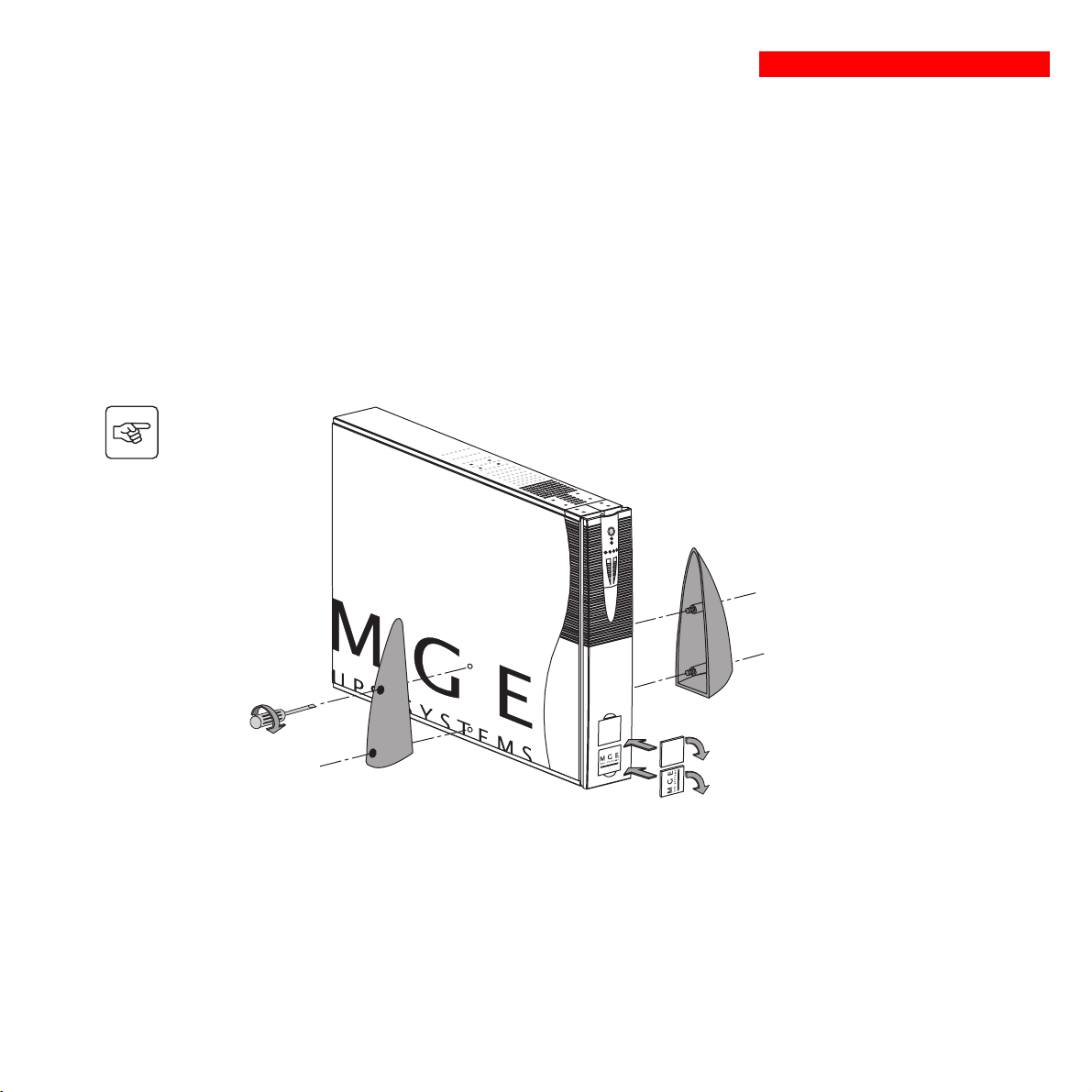
2.2 Upright installation (tower position)
Connect the two supports for the upright position.
2. Installation
P U L S A R
Evolution
3 0 0 0
3 0 0 0
Evolution
P U L S A R
34007115EN/AA - Page 11
Page 13
2. Installation
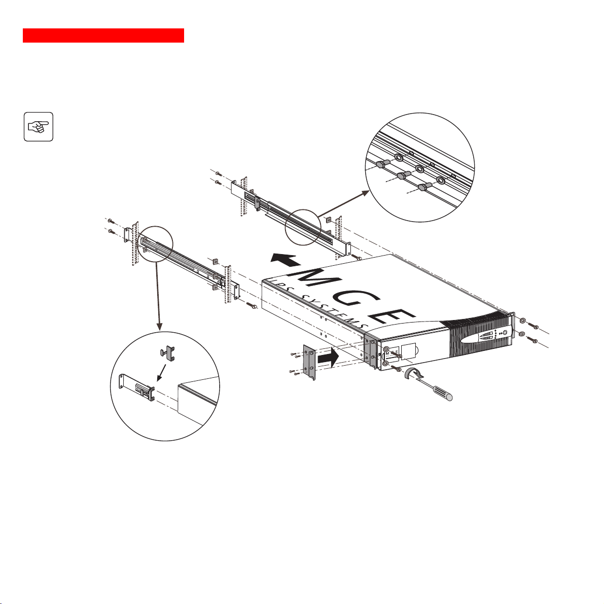
2.3 Flat installation (rack position)
Follow steps 1 to 6 for rack mounting of the UPS on the rails.
2
1
6
2
2
4
3
2
P U L S A R
Evolution
3 0 0 0
5
6
5
3
Page 12 - 34007115EN/AA
The rails and the necessary mounting hardware are supplied by MGE UPS SYSTEMS.
Page 14
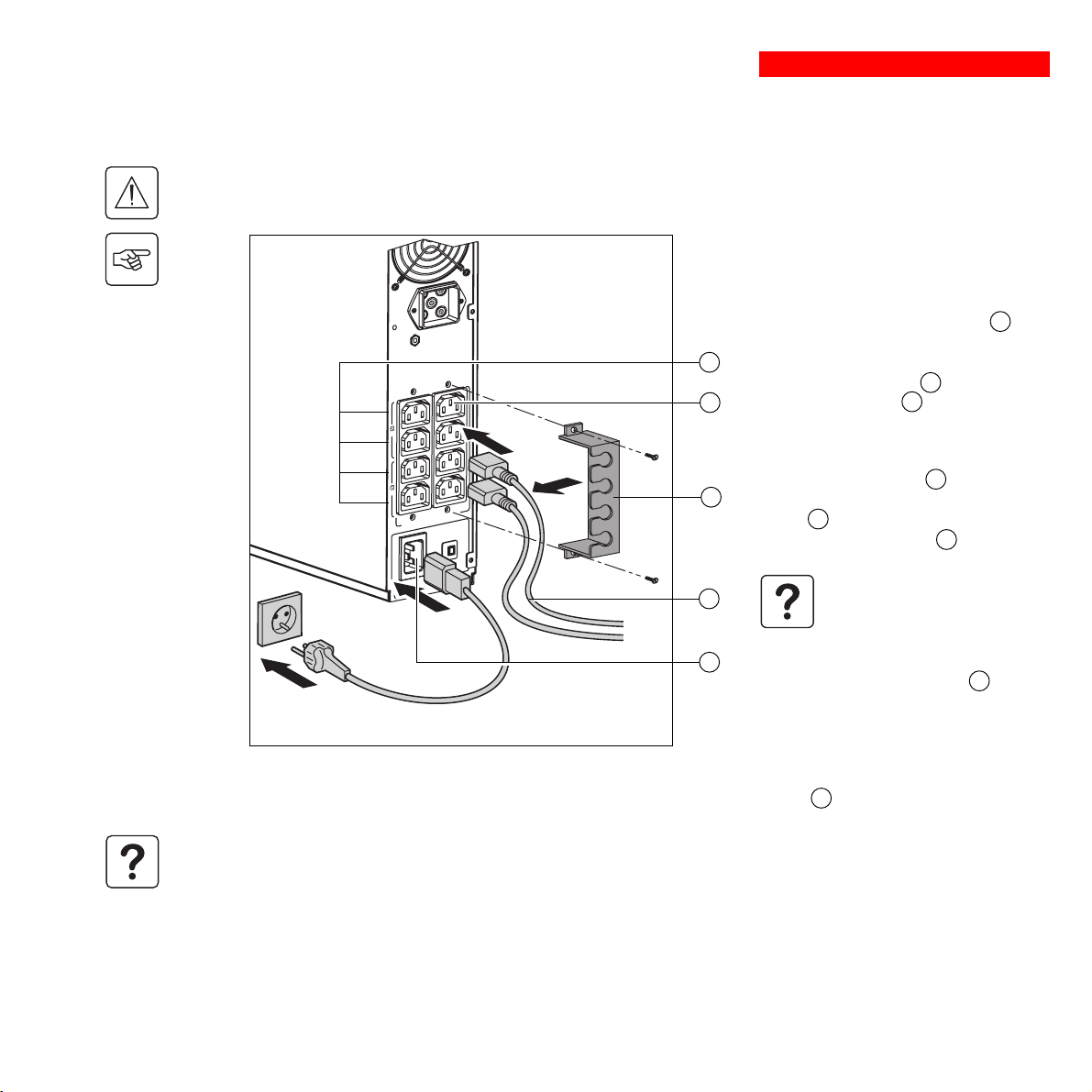
2.4 Connecting the protected equipment
Check that the indications on the rating plate on the back of the UPS correspond to your AC-power system and to
the actual electrical consumption of all the equipment to be connected to the UPS.
1
1 2
2
Us/Out/Ausg I max 10A
Ue/In/Eing 230V/10A Max
25
11
2. Installation
1 - Remove the power cord supplying the
equipment to be protected.
2 - Pulsar Evolution 2200: Connect the
power cord
equipment to the AC-power socket 11 and
then to the AC-power wall outlet.
- Pulsar Evolution 3000/3000 XL: Connect
9
the supplied power cord 24 (250 V, 16 A) to
the AC-power socket 11 and then to the
8
AC-power wall outlet.
3 - Connect the protected equipment to the
UPS using the two cords 25 . It is advised
29
to connect priority loads to the four standard
outlets 8 and any non-priority loads to the
four programmable outlets 9 (in groups of
two outlets).
(1)
just removed from the
If the UPS is connected to a
computer running MGE
communications software, it is
possible to program the
interruption of power to the
programmable outlets 9 during
operation on battery power, thus
reserving backup power for the
priority loads.
4 - Lock the connections using the securing
system 29 .
As soon as the UPS is energised, the battery begins charging. Eight hours are required to charge to the full rated
backup time.
Pulsar Evolution 3000 XL: At least one EXB additional battery module must be connected to the UPS because it does not
have internal batteries. See the EXB battery-module installation manual (Doc. no. 3400711600) for information on making
the connections.
(1) Make sure the cord has the following
characteristics: 250 V, 10 A, cross-sectional area 1
2
, type HO5.
mm
34007115EN/AA - Page 13
Page 15
2. Installation
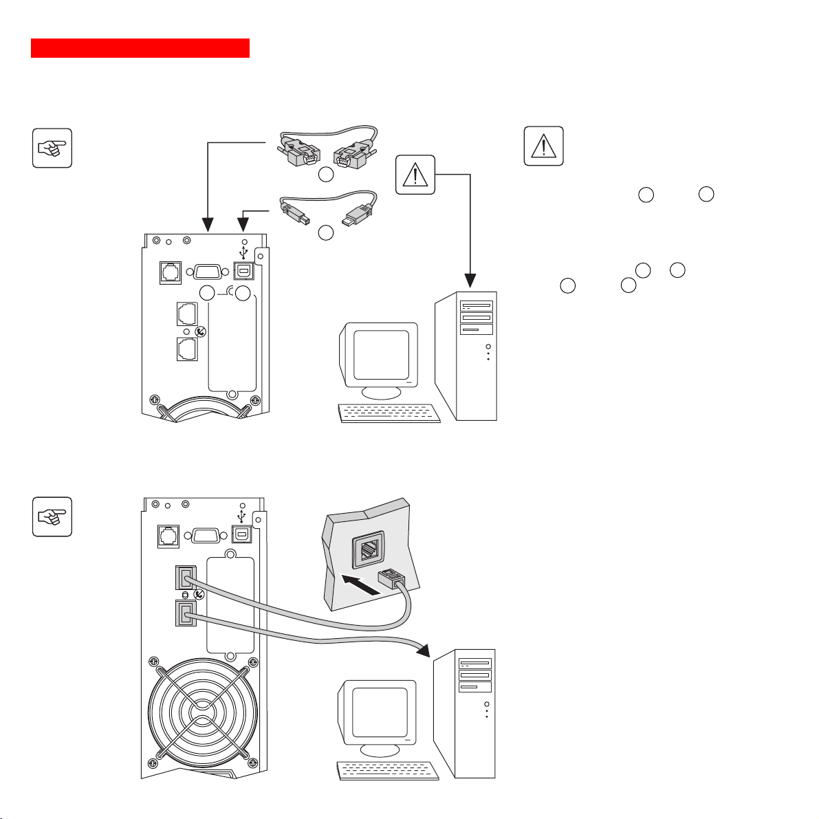
2.5 Connection to the RS232 or USB communications port (optional)
The RS232 and USB
communications ports cannot
operate simultaneously.
TO BATTERY
CABINET
IN OUT
RS232
2
1
DATA LINE PROTECTION
26
27
1 - Connect the RS232 26 or USB 27
communications cable to the serial port or
the USB port on the computer.
2 - Connect the other end of the
communications cable 26 or 27 to the
RS232 2 or USB 1 communications
port on the UPS.
The UPS can now communicate with all
MGE UPS SYSTEMS supervision, set-up or
safety software.
2.6 Connection to the data-line protection port (optional)
The data-line protection function on the UPS
eliminates overvoltages flowing on the
computer-network lines.
Simply connect the line to be protected to
the UPS using the data-line protection
connectors (IN and OUT) as indicated
opposite (RJ45 cables not supplied).
Page 14 - 34007115EN/AA
TO BATTERY
CABINET
IN OUT
RS232
DATA LINE PROTECTION
Page 16

2.7 Installation of the communications-card option
2. Installation
IN OUT
RS232
DATA LINE PROTECTION
5
TO BATTERY
CABINET
Slot for the communications-card
option.
It is not necessary to shut down the UPS to install the communications card.
1 - Remove the slot cover 5 secured by
two screws.
2 - Insert the card in the slot.
3 - Secure the cover with the two screws.
34007115EN/AA - Page 15
Page 17
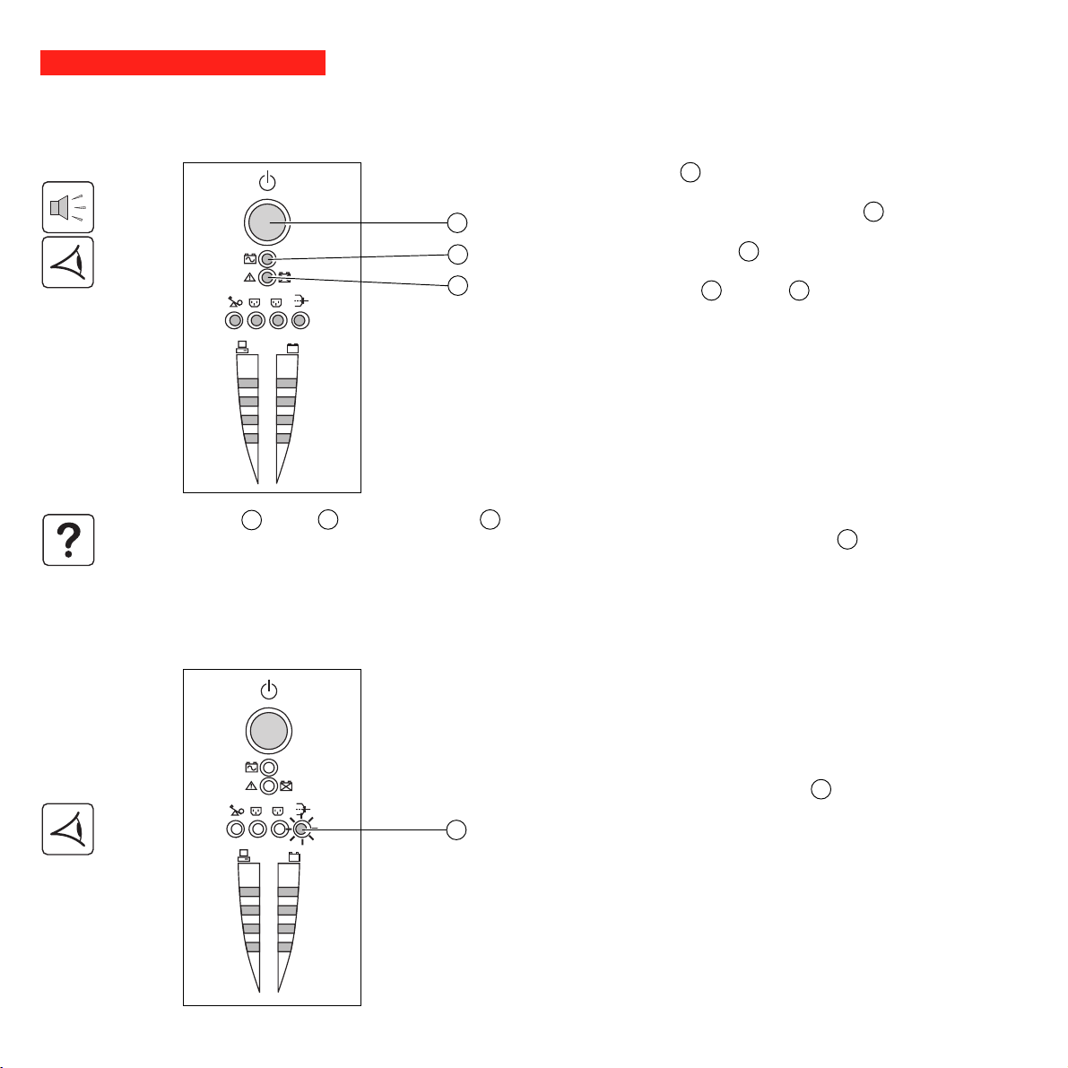
3. Operation
3.1 Start-up
Press the ON / OFF button 15 .
The buzzer beeps and all the LEDs come ON.
The buzzer beeps twice during the self-test, then button 15 remains
15
ON, indicating that the outlets are supplied with power.
- AC power is present: Only button 15 is ON. The protected
16
equipment is supplied by the AC-power source.
17
1
2
%
%
If button 15 or LED 16 are not ON or if LED 17 is ON, there is a fault (see section 4.1).
Note: The battery is charged as soon as the UPS is connected to the AC-power source, even if button 15 is in the OFF
position.
3.2 Shift to booster or fader mode
(during voltage variations in the AC-input power)
1
2
21
%
%
- AC power is absent: Button 15 and LED 16 are ON. The protected
equipment is supplied by the UPS, operating on battery power.
All the connected equipment is supplied with power.
The booster and fader functions maintain the output voltage supplied by
the UPS within close tolerances around the rated value even if
significant voltage variations occur in the AC-input power. This avoids
calling on battery power.
The values defining the voltage range may be set using the UPS Driver
software.
During operation in booster or fader mode, LED 21 is ON, signalling a
significant voltage variation in the AC-input power.
Page 16 - 34007115EN/AA
Page 18
3. Operation
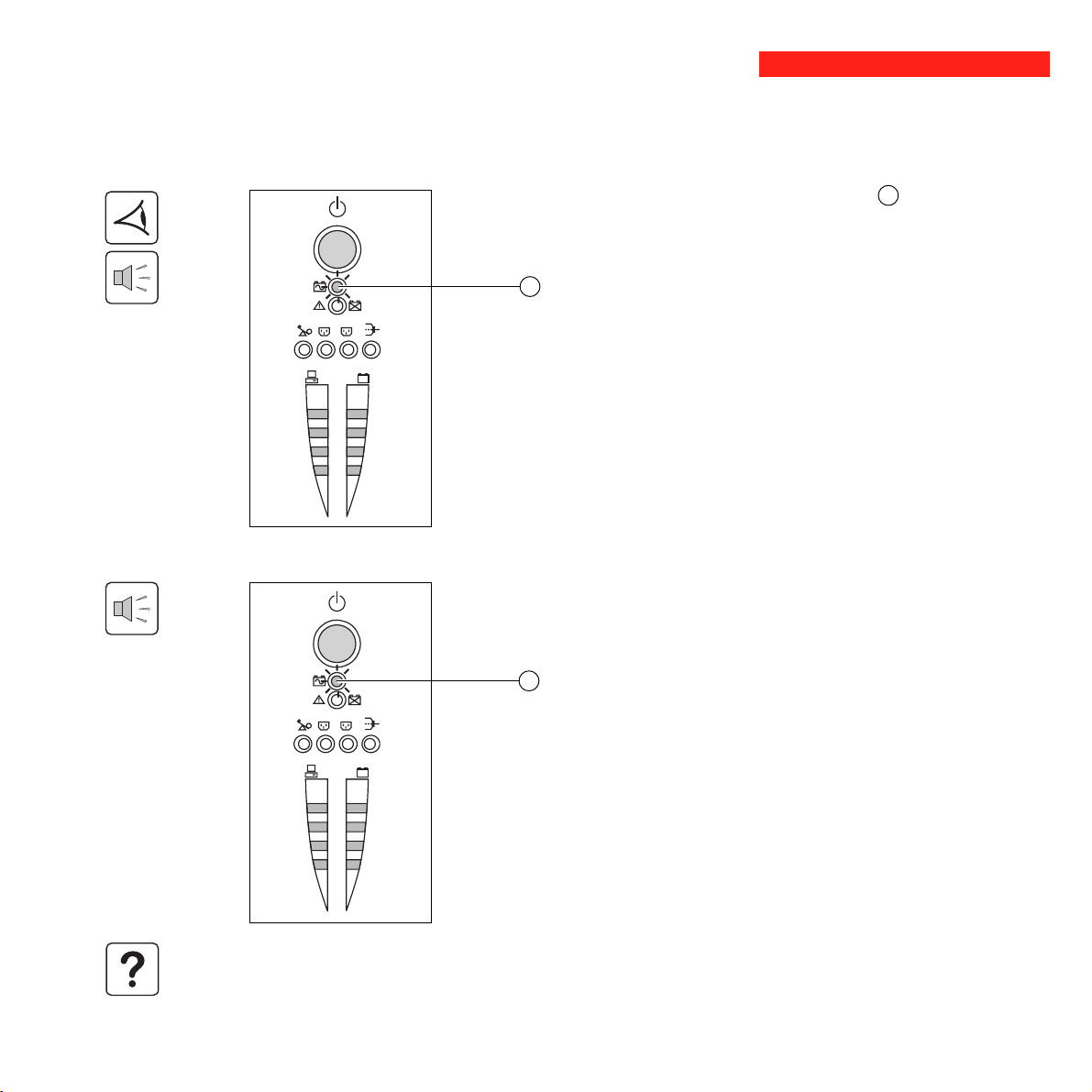
3.3 Operation on battery power (following failure of AC-input power)
Transfer to battery power
The AC-input power is out of tolerances, LED 16 goes ON.
During operation on battery power, the buzzer beeps every ten seconds.
The equipment connected to the UPS is supplied by the battery.
16
1
2
%
%
Threshold for the low-battery warning
When the threshold is reached, the buzzer beeps every three seconds.
The low-battery warning threshold can be set by the user, with the “UPS
Driver” software.
There is very little remaining battery backup time. Close all
16
applications because UPS automatic shutdown is imminent.
1
2
When the battery reaches the end of its backup time, the UPS shuts
down and all the LEDs go OFF.
%
%
The equipment is no longer supplied with power.
The UPS automatically restarts when power returns.
If the UPS does not restart, check that the “automatic restart when power returns” function has not been disabled (see
section 3.4 Personalisation).
34007115EN/AA - Page 17
Page 19
3. Operation
3.4 Personalisation (optional)
Function
Personalisation parameters can be set and modified using the UPS Driver software installed on a computer that is
connected to the UPS (see section 2.5 Connection to the RS232 communications port).
Check that the RS232 26 communications cable is connected.
UPS Driver installation:
1 - Insert the Solution-Pac CD-ROM containing the UPS Driver software in the drive of a PC running Windows.
2 - Open the Windows File manager or Explorer and select the CD-ROM drive.
3 - Double-click "\Emb\Evolutio\Config\Setup.exe".
Once UPS Driver has been installed, UPS parameters can be modified in a window containing a number of tabs, each
presenting a set of parameters :
ON / OFF conditions tab
Battery tab
Page 18 - 34007115EN/AA
Configurable function
Automatic restart
Cold start
Forced reboot
Energy saving
UPS ON / OFF via software
Configurable function
Interval between automatic battery tests
Low-battery warning threshold
Configuration of additional battery modules
Protection against deep discharges
Default setting
Enabled
Enabled
Enabled
Disabled
Enabled
Default setting
Once a week
20% of the remaining battery
backup time
Display the number of standard
EXB modules connected
to the UPS
Enabled
Options
Disabled
Disabled
Disabled
Enabled
Disabled
Options
Every day
Once a month
No test
10 to 40% of the remaining battery
backup time
Back-up time for non-standard
batteries (for 3000XL only)
Disabled
Page 20
Voltage-thresholds tab
3. Operation
Sensitivity tab
Configurable function
Output voltage on battery power
Upper threshold for transfer to battery power
Fader-mode cut-in threshold
Booster-mode cut-in threshold
Lower threshold for transfer to battery power
Maximum input-voltage range
(1) Lower threshold for transfer to battery power = 150 V
Configurable function
UPS sensitivity level
For more informations about these settings, refer to the Help function of the "UPS Driver" software.
Default setting
230 V
294 V
265 V
184 V
160 V
Disabled
Default setting
Normal
200 V - 220 V - 240 V
Options
271 to 294 V
244 to 265 V
184 to 207 V
160 to 180 V
Enabled
High or low
(1)
Options
34007115EN/AA - Page 19
Page 21
4. Maintenance
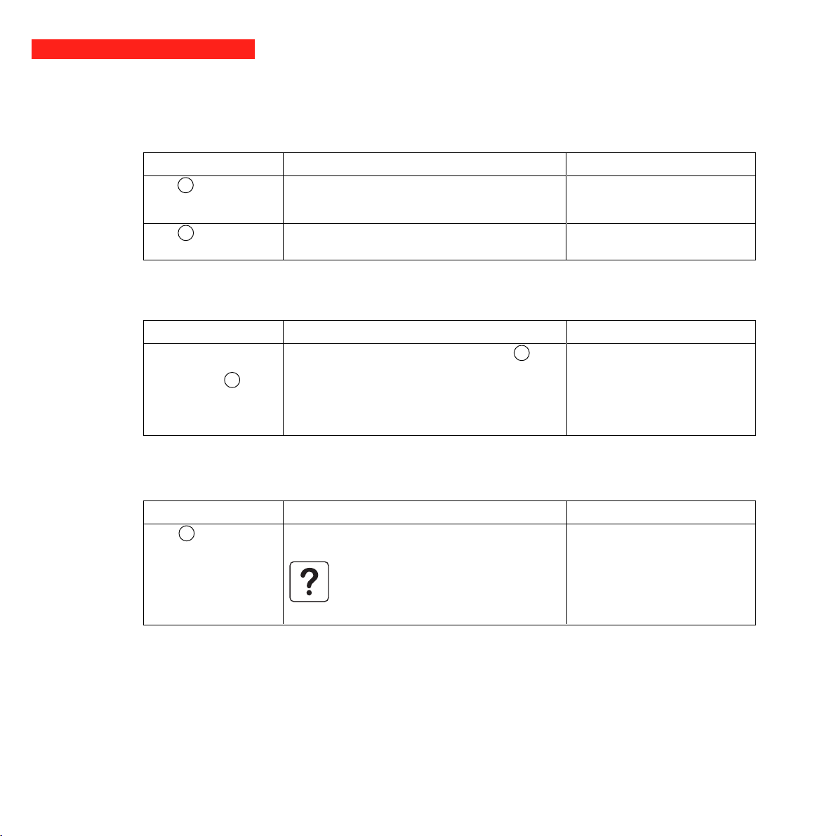
4.1 Trouble-shooting
Troubleshooting not requiring MGE UPS SYSTEMS after-sales support (all versions)
Indication
LED 18 flashes and the
buzzer beeps once.
LED 17 flashes.
UPS overload. The power drawn by the connected
equipment exceeds UPS capacity.
A battery fault was detected during the automatic
battery test.
Signification
Correction
Check the power drawn by the
equipment and disconnect any nonpriority devices.
Replace the battery module (see
section 4.2).
Troubleshooting not requiring MGE UPS SYSTEMS after-sales support (3000/3000 XL versions only)
Indication
The outlets are not
supplied with power even
though button 15 is ON.
One of the output-protection circuit breakers 7
on the rear panel is open.
Signification
Correction
◗ Make sure there is not a short-
circuit on the outlets.
◗ Clear the overload on the
concerned outlets by balancing the
equipment loads over the outlets.
◗ Close the circuit breaker.
Troubleshooting requiring MGE UPS SYSTEMS after-sales support
Indication
LED 17 goes ON and
the buzzer sounds
continuously.
UPS electronics have detected a UPS fault.
◗ The connected equipment is no longer supplied.
The equipment connected to the UPS is no
longer protected.
Signification
Correction
Call the after-sales support
department.
Page 20 - 34007115EN/AA
Page 22
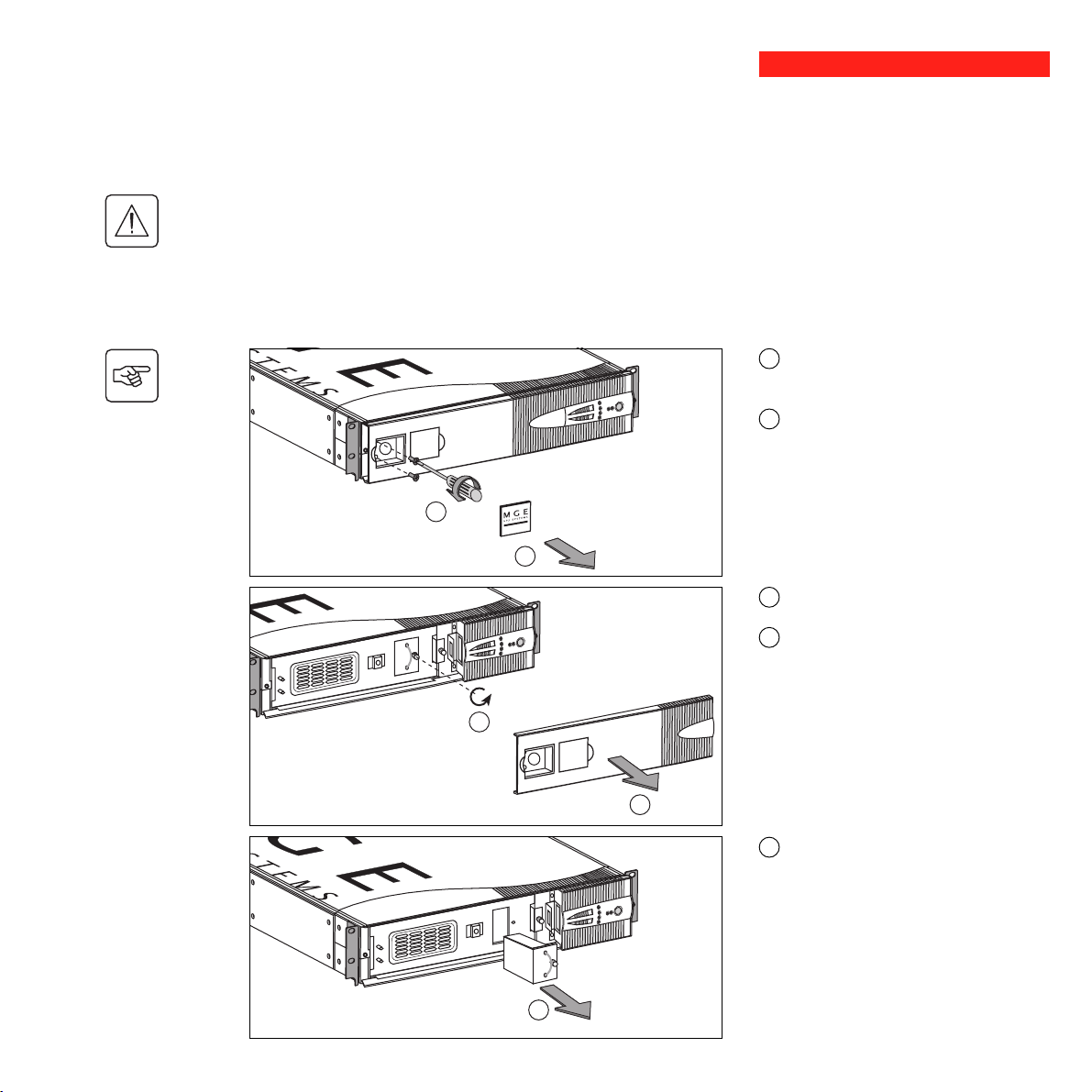
4.2 Replacement of the battery module
Safety rules
Batteries constitute a danger (electrical shock, burns). The short-circuit current may be very high. Precautions
must be taken for all handling:
◗ remove all watches, rings, bracelets and any other metal objects;
◗ use tools with insulated handles.
Removal of the battery module
This operation may be carried out with the UPS supplying power to the load.
P U L S A R
Evolution
3 0 0 0
B
A
4. Maintenance
A - Use a finger to unclip the small plate
with the MGE logo on the front panel of the
UPS.
B - Remove the two screws.
C - Pull away the left-hand side of the front
panel.
D - Remove the screw securing the safety
connector.
D
P U L S A R
Evolution
3 0 0 0
C
E - Remove the safety connector.
E
34007115EN/AA - Page 21
Page 23

4. Maintenance
F - Remove the screw securing the battery
cover.
G - Remove the cover.
F
G
H - Disconnect the battery module.
I - Remove the battery module.
H
Page 22 - 34007115EN/AA
I
Installation of the new battery module
Carry out the above operation in reverse order.
◗ To maintain an identical level of performance and safety, use a battery module identical to that previously
mounted in the UPS.
◗ Press the two parts of the battery connector tightly together to ensure proper connection.
Page 24

5. Environment
This product has been designed to respect the environment:
It does not contain CFCs or HCFCs.
UPS recycling at the end of service life:
MGE UPS SYSTEMS undertakes to recycle, by certified companies and in compliance with all applicable regulations, all
UPS products recovered at the end of their service life (contact your MGE branch office).
Packing:
UPS packing materials must be recycled in compliance with all applicable regulations.
Warning:
This product contains lead-acid batteries. Lead is a dangerous substance for the environment if it is not properly recycled
by specialised companies.
Web site: www.mgeups.com
34007115EN/AA - Page 23
Page 25
6. Appendices
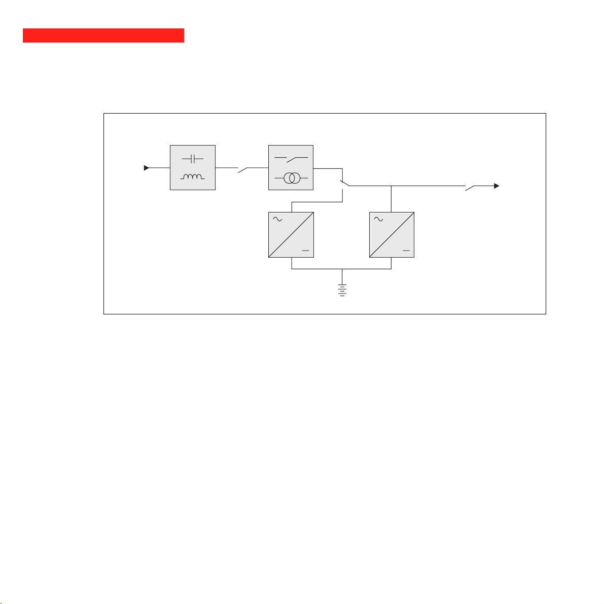
6.1 Technical data
Simplified diagram
Input
Booster / fader transformerFilter
Output
Inverter
Charger
Battery
Page 24 - 34007115EN/AA
Page 26
Technical characteristics
6. Appendices
Output rating
Pulsar Evolution 2200
2200 VA / 1540 W
(1)
Pulsar Evolution 3000
3000 VA / 2000 W
AC-input power
◗ Voltage
◗ Frequency
Single-phase, 160 V to 294 V
47 Hz to 70 Hz (50 Hz system) or 56.5 Hz to 70 Hz
(2)
Output power (operation
on battery power)
◗ Voltage
◗ Frequency
Battery
6 x 12 V, 7 Ah, sealed lead-
acid, maintenance free
Single-phase, 230 V
50/60 Hz +/- 0,1 Hz
6 x 12 V, 9 Ah, sealed
lead-acid, maintenance free
(4)
(+ 6% / - 10%)
Environment
◗ Noise level (operation on
<40 dBA
AC-input power)
◗ Operating temperature
◗ Relative humidity
20 to 90% (without condensation)
0 to 40° C
(1) Above 184 V on normal utility power. Below this value, the level of output power is lower.
(2) The upper and lower thresholds may be set using the UPS Driver software.
(3) Or 40 Hz in low-sensitivity mode (may be set using the UPS Driver software).
(4) Adjustable from 200 to 240 V using the UPS Driver software.
Pulsar Evolution 3000 XL
3000 VA / 2000 W
(3)
(60 Hz system)
external
34007115EN/AA - Page 25
Page 27
6. Appendices
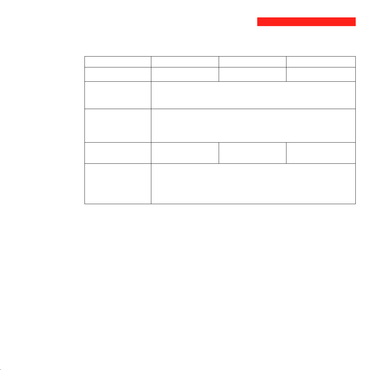
Examples of battery backup times
Pulsar Evolution 2200
1 data server
+ 1 hard disk
2 distributed servers
+ 1 hub
8 rack-mounted servers
0 5 10 15 20 25 30 t (min)
Pulsar Evolution 3000
1 data server
+ 1 hard disk
4 distributed servers
+ 1 hub + 1 router
Page 26 - 34007115EN/AA
12 rack-mounted servers
0 5 10 15 20 25 30 t (min)35
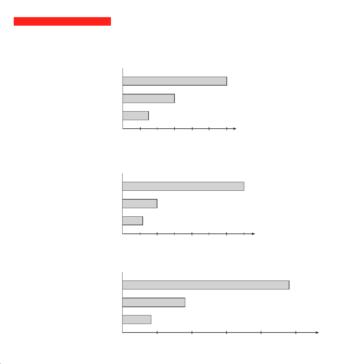
Pulsar Evolution 3000 XL + 3 EXB
1 telecom device
1 set of telecom devices
1 large set of telecom
devices
0 100 200 300 400 500 t (min)
Page 28

6.2 Glossary
Backup time Time that the connected equipment can operate on battery power if AC-input power fails.
Bargraph Device on the front panel indicating the percent remaining backup time or the percent
Battery module (additional) Additional battery modules connected in parallel to increase the UPS backup time.
Booster mode Automatic UPS operating mode whereby the input-power voltage is increased if it drops
De-energised The UPS must be physically disconnected from the AC-input power.
Equipment Devices and systems connected to the UPS output.
Fader mode Automatic UPS operating mode whereby the input-power voltage is decreased if it rises
Input circuit breaker Circuit breaker protecting the upstream distribution system against UPS faults.
Outlets Pulsar Evolution has a group of four non-programmable outlets.
Output circuit breaker Circuit breaker protecting the UPS against high overloads or faults on the connected
6. Appendices
load.
below a value set in the personalisation parameters, thus avoiding a battery discharge.
above a value set in the personalisation parameters, thus avoiding a battery discharge.
equipment.
Personalisation The parameters for a number of UPS functions may be modified using the UPS Driver
software to adapt UPS operation to user needs.
RS232 communications port For UPS connection to a computer via the serial port.
Programmable outlets Pulsar Evolution has two groups of two programmable outlets. They may be used for
sequential start-up of protected equipment, shedding of non-priority loads during
operation on battery power or management of operating priorities to provide the most
critical devices with more backup time before battery power runs out. These outlets may
be programmed using the Solution-Pac software on the CD-ROM supplied with the
UPS.
Solution-Pac MGE UPS SYSTEMS safety, set-up and supervision software suite on the CD-ROM
supplied with the UPS.
UPS Uninterruptible Power Supply.
UPS Driver Communications software on the CD-ROM supplied with the UPS. It may be used to
personalise the default settings.
USB communications port For UPS connection to a computer via the USB port.
34007115EN/AA - Page 27
Page 29

6. Appendices
6.3 Index
A
Automatic start ............................................................... 18
B
Bargraph .......................................................................... 9
Battery
Additional modules ................................................... 8
Backup time ............................................................ 26
End of backup time ................................................. 17
Fault ......................................................................... 9
Personalisation ....................................................... 18
Recycling ................................................................ 23
Replacement .................................................... 21, 22
Threshold for low-battery warning .......................... 17
Transfer to battery power ................................... 9, 17
Buttons ............................................................................. 9
Buzzer ............................................................................ 17
C
Circuit breakers
Battery circuit breaker .............................................. 8
Input circuit breaker .................................................. 8
Output circuit breaker ............................................... 8
Communication
Cards .................................................................. 8, 15
Ports ................................................................... 8, 14
Connections
Data-line protection ................................................ 14
RS232 communications port .................................. 14
USB communications port ...................................... 14
L
LEDs ................................................................................ 9
M
Mode
Booster mode ..................................................... 9, 16
Fader mode ........................................................ 9, 16
Sleep mode (automatic start) ................................. 18
O
Overloads ................................................................... 9, 20
P
Personnalisation ........................................................... 18
Battery ....................................................................18
ON / OFF conditions .............................................. 18
Output .................................................................... 19
Ports
RS232 ................................................................8, 14
USB ....................................................................8, 14
Programmable outlets ..................................................8, 9
S
Safety .............................................................................21
Start-up .......................................................................... 16
T
Technical characteristics ................................................25
Temperature (excessive ambient) ..................................25
Page 28 - 34007115EN/AA
D
Dimensions ...................................................................... 7
E
Environment ................................................................... 23
F
Fault (UPS) ...................................................................... 9
U
UPS Driver .................................................. 16, 17, 18, 25
UPS ON / OFF via software ...........................................18
W
Web site ........................................................................ 23
Weight ..............................................................................7
Page 30

3400711500/AA
Page 31

www.mgeups.com
MGE UPS SYSTEMS
Pulsar Evolution
2200/3000/3000 XL
Manuel d'installation
et d'utilisation
R
E
T
Ê
R
R
A
S
U
O
V
T
I
O
D
E
N
N
E
I
R
34007115FR/AA - Page 1
Page 32

Page 2 - 34007115FR/AA
Page 33

Introduction
Nous vous remercions d'avoir choisi un produit MGE UPS SYSTEMS pour assurer la sécurité des équipements qu'il
alimente.
La gamme Pulsar Evolution a été élaborée avec le plus grand soin.
Pour exploiter au mieux les performances de l'ASI (Alimentation Sans Interruption), nous vous conseillons de prendre le
temps de lire ce manuel.
MGE UPS SYSTEMS se préoccupe de l'impact de ses produits sur l'environnement.
Les ressources mises en oeuvre font de Pulsar Evolution une référence en matière de protection de l'environnement dont
en particulier :
◗ une démarche d'éco-conception pendant son cycle de développement,
◗ le recyclage de Pulsar Evolution en fin de vie du produit.
Nous vous invitons à découvrir l'offre de MGE UPS SYSTEMS ainsi que les options de la gamme Pulsar Evolution en
visitant notre site WEB à www.mgeups.com ou en contactant votre représentant MGE UPS SYSTEMS.
34007115FR/AA - Page 3
Page 34

Avant propos
Structure de la documentation
La recherche d’information s’effectue de deux façons :
◗ par le sommaire,
◗ par l’index.
Conventions des pictogrammes
Suivre impérativement ces consignes.
Informations, conseils, aide.
Signalisation visuelle.
Action.
Signalisation sonore.
Page 4 - 34007115FR/AA
Les conventions adoptées pour représenter les voyants dans les illustrations sont les suivantes :
Voyant éteint.
Voyant allumé.
Voyant clignotant.
Page 35

Sommaire
1. Présentation
1.1 Vues générales............................................................................................................................ 7
Position "tour" ................................................................................................................................. 7
Position "rack" ................................................................................................................................. 7
1.2 Faces arrières.............................................................................................................................. 8
1.3 Panneau de contrôle..................................................................................................................... 9
2. Installation
2.1 Déballage et vérification............................................................................................................. 10
2.2 Mise en place en position "tour" ............................................................................................... 11
2.3 Mise en place en position "rack"............................................................................................... 12
2.4 Raccordement des équipements............................................................................................... 13
2.5 Raccordement du port de communication RS232 ou USB (facultatif) .................................... 14
2.6 Raccordement de la protection ligne de données (facultatif) .................................................. 14
2.7 Mise en place de l’option "carte de communication".............................................................. 15
3. Utilisation
3.1 Mise en marche ........................................................................................................................... 16
3.2 Passage en mode "booster" ou "fader" (en cas de variation de tension du réseau électrique)16
3.3 Alimentation sur batterie (en cas d'absence du réseau électrique) ........................................... 17
Passage sur batterie ..................................................................................................................... 17
Seuil d’alarme de fin d’autonomie batterie atteint ......................................................................... 17
3.4 Personnalisation (facultatif) ........................................................................................................ 18
Fonction ........................................................................................................................................ 18
Onglet "Conditions On/Off" ........................................................................................................... 18
Onglet "Batterie" ........................................................................................................................... 18
Onglet "Seuils de tension" ............................................................................................................ 19
Onglet "Sensibilité" ....................................................................................................................... 19
4. Maintenance
4.1 Dépannage................................................................................................................................... 20
4.2 Remplacement du module batterie ........................................................................................... 21
5. Environnement ................................................................................................................................23
34007115FR/AA - Page 5
Page 36

Sommaire
6. Annexes
6.1 Caractéristiques techniques ...................................................................................................... 24
Schéma synoptique ...................................................................................................................... 24
Caractéristiques techniques.......................................................................................................... 25
Exemples d'autonomies batterie ................................................................................................... 26
6.2 Glossaire...................................................................................................................................... 27
6.3 Index............................................................................................................................................. 28
Page 6 - 34007115FR/AA
Page 37

1.1 Vues générales
Position "tour"
1. Présentation
Dimensions en mm
(L x H x P)
Evolution 2200
Evolution 3000
Evolution 3000 XL
438 x 87,9 x 640
(19") (2U)
Poids en kg
Position "rack"
P U L S A R
Evolution
3 0 0 0
P U L S A R
Evolution
3 0 0 0
Evolution 2200
Evolution 3000
Evolution 3000 XL
34
37
21
P
H
L
34007115FR/AA - Page 7
Page 38

1. Présentation
1.2 Faces arrières
Pulsar Evolution 2200
RS232
DATA LINE PROTECTION
IN OUT
TO BATTERY
CABINET
1 234 115 1098
Pulsar Evolution 3000 / 3000 XL
RS232
DATA LINE PROTECTION
IN OUT
TO BATTERY
CABINET
Port de communication USB.
1
2
Port de communication RS232.
Us/Out/Ausg I max 10A
Ue/In/Eing 230V/10A Max
3
1 2
1
2
Connecteur de reconnaissance
automatique d'un module batterie
supplémentaire.
6
Protection des lignes de données.
4
Emplacement pour l'option "carte de
5
communication".
6
Connecteur pour le raccordement d'un
AB
1
2
AB
1 2
2
1
Us/Out/Ausg I max 13A
Ue/In/Eing 230V/16A Max
module batterie supplémentaire.
Disjoncteurs de protection des sorties.
7
8
Groupe de 4 prises pour le
raccordement des équipements.
Page 8 - 34007115FR/AA
8
1 234 115 109
7
6
Module d'extension batterie EXB
12 14
13
12
9
2 groupes de 2 prises programmables
(groupe 1 et 2).
Disjoncteur de protection du réseau
10
électrique d'alimentation.
11
Prise pour le raccordement au réseau
électrique d'alimentation.
12
Connecteurs pour le raccordement des
modules batterie (vers l'ASI ou vers les
autres modules batterie).
13
Connecteurs de reconnaissance
automatique des modules batterie.
14
Disjoncteur de protection et de mise en
fonction de la batterie.
Page 39

1.3 Panneau de contrôle
1. Présentation
15
Bouton lumineux Marche/Arrêt (ON/OFF) des prises de sortie.
16
Fonctionnement sur batterie.
17
Défaut de l'appareil.
Défaut batterie.
ASI en surcharge.
18
Prises programmables 1 alimentées.
1
2
%
%
19
Prises programmables 2 alimentées.
20
21
Fonctionnement en mode "booster" ou "fader".
22
Barregraphe du niveau de puissance utilisée en sortie.
23
Barregraphe du niveau de charge de la batterie.
De 76 à 100%.
De 51 à 75%.
De 26 à 50%.
De 0 à 25%.
34007115FR/AA - Page 9
Page 40

2. Installation
2.1 Déballage et vérification
24
25
28
P U L S A R
Evolution
3 0 0 0
24
Cordon de raccordement au réseau électrique pour le modèle 3000/3000 XL uniquement
31
(dans le cas du modèle 2200, utiliser le cordon d'alimentation de l'équipement).
25
2 cordons pour raccorder les équipements.
Câble de communication RS 232.
26
27
Câble de communication USB.
Kit de montage en armoire 19".
28
2 systèmes de verrouillage des cordons d'alimentation des équipements.
29
30
CD ROM contenant les logiciels "Solution Pac" et "UPS Driver".
31
Documentation.
2 pieds de maintien en position verticale.
32
26
27
29
30
32
Page 10 - 34007115FR/AA
Page 41

2.2 Mise en place en position "tour"
Montage des pieds de maintien en position verticale.
2. Installation
P U L S A R
Evolution
3 0 0 0
3 0 0 0
Evolution
P U L S A R
34007115FR/AA - Page 11
Page 42

2. Installation
2.3 Mise en place en position "rack"
Montage et fixation des glissières et du rack : suivre les étapes 1 à 6.
2
1
6
2
2
4
3
2
P U L S A R
Evolution
3 0 0 0
5
6
5
3
Page 12 - 34007115FR/AA
La visserie de fixation et les glissières sont fournies par MGE UPS SYSTEMS.
Page 43

2.4 Raccordement des équipements
Vérifier que les indications portées sur la plaque d'identification située à l'arrière de l'appareil correspondent au
réseau électrique d'alimentation et à la consommation électrique réelle des équipements.
1
1 2
2
Us/Out/Ausg I max 10A
Ue/In/Eing 230V/10A Max
25
11
2. Installation
1 - Débrancher le cordon d'alimentation de
l'équipement.
2 - Pulsar Evolution 2200 : connecter ce
(1)
cordon
du réseau électrique d'alimentation.
- Pulsar Evolution 3000/3000XL, connecter
le cordon d'alimentation 24 fourni (250V -
9
16A) sur la prise 11 , puis sur la prise du
réseau électrique d'alimentation.
8
3 - Raccorder les équipements à l'ASI à
l'aide des cordons 25 .
Connecter de préférence les équipements
29
prioritaires sur les 4 prises ␣ 8 et les
équipements non prioritaires sur les 4 prises
␣ ␣ 9 programmables par paire (1 et 2).
sur la prise 11 , puis sur la prise
Pour pouvoir programmer l'arrêt
des prises ␣ ␣ 9 en cours
d'autonomie batterie et optimiser
ainsi la durée de cette autonomie,
il est nécessaire d'avoir accès au
logiciel de communication MGE
UPS SYSTEMS.
4 - Verrouiller le raccordement en fixant le
système 29 .
Après la première mise sous tension, il faut au moins 8␣ heures pour que la batterie puisse fournir l'autonomie
nominale.
Pulsar Evolution 3000 XL : au moins 1 coffret d'extension batterie EXB doit être raccordé à ce modèle qui ne comporte
pas de batteries internes. Se référer au manuel d'installation du coffret batterie EXB n° 3400711600 pour la connexion.
(1) S'assurer que les caractéristiques de ce cordon
sont : 250V - 10A (section 1mm
2
, type HO5).
34007115FR/AA - Page 13
Page 44

2. Installation
2.5 Raccordement du port de communication RS232 ou USB (facultatif)
Le port de communication RS232
et le port de communication USB
ne peuvent pas fonctionner
simultanément.
TO BATTERY
CABINET
IN OUT
RS232
2
1
DATA LINE PROTECTION
26
27
1 - Connecter le câble de communication
RS␣ 232 26 ou USB 27 sur le port série
ou USB de l'équipement informatique.
2 - Connecter l'autre extrémité du câble de
communication 26 ou 27 sur le port
de communication RS232 2 ou USB 1
de l’ASI.
L'ASI peut désormais dialoguer avec un
logiciel d'administration, de personnalisation
ou de sécurité MGE UPS SYSTEMS.
2.6 Raccordement de la protection de la ligne de données (facultatif)
La fonction "protection des lignes de
données" de l'ASI permet d'éliminer les
surtensions véhiculées sur les lignes des
réseaux informatiques.
Pour cela, faire transiter la ligne à protéger
par l'ASI, en utilisant les prises "Data ligne
protection" IN (entrée) et OUT (sortie)
comme indiqué sur la figure ci-contre
(câbles RJ45 non fournis).
Page 14 - 34007115FR/AA
TO BATTERY
CABINET
IN OUT
RS232
DATA LINE PROTECTION
Page 45

2.7 Mise en place de l’option "carte de communication"
2. Installation
IN OUT
RS232
DATA LINE PROTECTION
5
TO BATTERY
CABINET
Emplacement de la carte
de communication.
Il n'est pas nécessaire d'arrêter l'ASI pour installer une carte de communication.
1 - Oter le plastron 5 de l'ASI fixé par 2
vis.
2 - Glisser la carte dans l'emplacement
prévu.
3 - Fixer le plastron de la carte à l'aide des 2
vis.
34007115FR/AA - Page 15
Page 46

3. Utilisation
3.1 Mise en marche
Appuyer sur le bouton 15 .
Le buzzer émet un bip et tous les voyants s'allument simultanément.
Le buzzer émet ensuite 2 bips pendant l'autotest, puis le bouton 15
15
reste allumé signalant l'alimentation des prises de sortie.
- Réseau électrique d'alimentation présent : seul le bouton 15 est
16
allumé. Les équipements sont alimentés par le réseau électrique.
17
1
2
%
%
Si les voyants 15 ou 16 ne s’allument pas ou si le voyant ␣ 17 est allumé, un défaut est présent (voir chapitre 4.1).
Nota : l'appareil recharge la batterie dès qu'il est raccordé au réseau électrique, même sans appuyer sur le bouton 15 .
3.2 Passage en mode "booster" ou "fader"
(en cas de variation de tension du réseau électrique)
1
2
21
%
%
- Réseau électrique d'alimentation absent : le bouton 15 et le voyant
␣ 16 sont allumés. Les équipements sont alimentés par l'ASI qui
fonctionne sur batterie.
L’ensemble des équipements connectés est alors sous tension.
Les fonctions "booster" et "fader" permettent de maintenir la tension de
sortie délivrée par l'ASI dans une plage définie autour de la valeur
nominale, en cas de variation d'amplitude plus importante du réseau
électrique d'alimentation, et ceci sans décharger la batterie.
Les valeurs de cette plage de fonctionnement sont configurables par
l'intermédiaire du logiciel "UPS Driver".
Lors du fonctionnement en mode "booster" ou "fader", le voyant 21 est
allumé, indiquant une variation d'amplitude importante du réseau
électrique d'alimentation.
Page 16 - 34007115FR/AA
Page 47

3. Utilisation
3.3 Alimentation sur batterie (en cas d’absence du réseau électrique)
Passage sur batterie
Lorsque le réseau électrique d'alimentation est hors tolérances, le
voyant 16 est allumé.
Durant toute la durée de l'autonomie batterie, le buzzer émet un bip
toutes les 10 secondes.
16
Les équipements connectés à l’ASI continuent d’être alimentés
1
2
%
%
Seuil d’alarme de fin d’autonomie batterie atteint
grâce à la batterie.
Lorsque ce seuil est atteint, le buzzer émet un bip toutes les 3 secondes.
Ce seuil peut se personnaliser via le logiciel "UPS Driver".
Il ne reste alors qu’une faible partie d’autonomie batterie, fermez
les applications car l’arrêt automatique de l’ASI est proche.
16
Lorsque la fin d'autonomie batterie est atteinte, l'ASI s'arrête et tous les
1
2
%
%
voyants sont éteints.
Les équipements connectés à l’ASI ne sont plus alimentés.
L'ASI redémarre automatiquement dès le retour du réseau électrique.
Si l’ASI ne redémarre pas, vérifiez que le redémarrage automatique sur retour du réseau électrique n’a pas été désactivé
(voir le chapitre 3.4 "Personnalisation").
34007115FR/AA - Page 17
Page 48

3. Utilisation
3.4 Personnalisation (facultatif)
Fonction
Il est possible de faire évoluer la personnalisation de l'ASI au moyen du logiciel "UPS Driver" installé sur un ordinateur
connecté à l’ASI selon la procédure "Raccordement du port de communication RS232" (voir chapitre 2.5).
Vérifier que le câble RS 232 26 est raccordé.
Installation du logiciel "UPS Driver" :
1 - Insérer le CD ROM "Solution Pac" contenant le logiciel "UPS Driver" dans le lecteur de votre micro-ordinateur
compatible Windows.
2 - Ouvrir le gestionnaire de fichier Windows ou l'explorateur et sélectionner le lecteur de CD ROM.
3 - Lancer "\Emb\Evolutio\Config\Setup.exe".
Après avoir installé "UPS Driver", vous pouvez modifier les paramètres de réglage suivants :
Onglet "Conditions On/Off"
Onglet "Batterie"
Protection contre les décharges profondes
Page 18 - 34007115FR/AA
Fonctions personnalisables
Redémarrage automatique
Démarrage sur batterie ("cold start")
Arrêt forcé
Mise en veille
Marche/Arrêt onduleur par logiciel
Fonctions personnalisables
Intervalle du test batterie automatique
Seuil "Alarme niveau bas" de la batterie
Configuration des extensions batterie
Configuration usine
Activé
Activé
Activé
Désactivé
Activé
Configuration usine
Toutes les semaines
20% de l’autonomie restante
Affiche le nombre de coffrets EXB
standards raccordés à l'ASI
Activé
Personnalisation possible
Désactivé
Désactivé
Désactivé
Activé
Désactivé
Personnalisation possible
Tous les jours
Tous les mois
Pas de test
De 10 à 40% de l’autonomie
restante
Durée d'autonomie pour les
batteries non standards
(pour 3000XL uniquement)
Désactivé
Page 49

Onglet "Seuils de tension"
3. Utilisation
Tension de sortie en fonctionnement sur batterie
Seuil haut de passage sur batterie
Seuil d'activation du mode "fader"
Seuil d'activation du mode "booster"
Seuil bas de passage sur batterie
Plage maximale de tension d'entrée
(1) Seuil bas de passage sur batterie = 150 V
Onglet "Sensibilité"
Pour plus d'informations concernant ces paramètres, se référer à la rubrique d'aide du logiciel "UPS Driver".
Fonctions personnalisables
Fonctions personnalisables
Niveau de sensibilité de l'ASI
Configuration usine
230 V
294 V
265 V
184 V
160 V
Désactivé
Configuration usine
Normal
Personnalisation possible
200 V - 220 V - 240 V
271 à 294 V
244 à 265 V
184 à 207 V
160 à 180 V
(1)
Activé
Personnalisation possible
Haute ou basse
34007115FR/AA - Page 19
Page 50

4. Maintenance
4.1 Dépannage
Dépannage sans intervention du SAV (tous modèles)
Symptôme
Le voyant 18 s'allume et
le buzzer émet un bip.
Le voyant 17 clignote.
L’ASI est en surcharge. La consommation électrique
des équipements raccordés à l'ASI dépasse la
capacité de celle-ci.
Un défaut batterie a été détecté lors du test
automatique de la batterie.
Diagnostic
Dépannage sans intervention du SAV (modèles 3000/3000 XL seulement)
Symptôme
Les prises de sortie ne
sont pas alimentées bien
que le bouton 15 soit
allumé.
Un des disjoncteurs de protection 7 des prises de
sortie est ouvert en face arrière.
Diagnostic
Dépannage avec intervention du SAV
Symptôme
Le voyant 17 s'allume
et le buzzer émet un bip
continu.
L’ASI présente un défaut détecté par l’électronique
interne.
◗ L’ensemble des équipements n’est plus alimenté.
Diagnostic
Remède
Vérifier la puissance absorbée par
les équipements et déconnecter les
équipements non prioritaires.
Remplacer les éléments batterie␣ :
voir le paragraphe 4.2.
Remède
◗ Vérifier l'absence de court-circuit
sur les prises de sortie.
◗ Eliminer la surcharge sur le
groupe de prises concerné en
répartissant différemment les
équipements sur les groupes de
prises.
◗ Refermer le disjoncteur.
Remède
Appeler le service après-vente.
Page 20 - 34007115FR/AA
Les équipements connectés à
l’ASI ne sont plus protégés.
Page 51

4.2 Remplacement du module batterie
Rappel sur les consignes de sécurité :
La batterie présente un risque de choc électrique et un courant de court-circuit élevé.
Les précautions suivantes doivent être prises pour toute intervention sur les éléments batterie :
◗ Oter des mains montres, bagues, alliances, bracelets ou tout autre objet métallique,
◗ Utiliser des outils isolés.
Démontage du module batterie
Cette opération peut s'effectuer sans arrêter l'ASI.
P U L S A R
Evolution
3 0 0 0
B
A
4. Maintenance
A - Glisser le doigt dans l'emplacement
prévu à cet effet pour déclipser la plaquette
supportant le logo MGE sur la face avant de
l'appareil.
B - Dévisser les deux vis placées derrière.
C - Retirer la section gauche de la face
avant en la tirant vers soi.
D - Dévisser la vis verrouillant le
connecteur de sécurité.
D
P U L S A R
Evolution
3 0 0 0
C
E - Extraire le connecteur de sécurité.
E
34007115FR/AA - Page 21
Page 52

4. Maintenance
F - Dévisser la vis fixant le capot batterie.
G - Enlever ce capot.
F
G
H - Débrancher le bloc batterie.
I - Extraire le bloc batterie et procéder à
son remplacement.
H
Page 22 - 34007115FR/AA
I
Remontage du nouveau module batterie
Réaliser les opérations décrites ci-dessus en sens inverse.
◗ Pour préserver la sécurité et le même niveau de performance, utiliser des éléments batterie identiques à ceux
montés dans l'ASI.
◗ Veillez à bien enfoncer les parties mâles et femelles du connecteur lors du raccordement.
Page 53

5. Environnement
Ce produit est conçu pour respecter l’environnement :
Il ne contient ni CFC ni HCFC.
Recyclage de l’ASI en fin de vie :
MGE UPS SYSTEMS s’engage à faire retraiter, par des sociétés agréées et conformes à la réglementation,
l’ensemble des produits qui sont récupérés en fin de vie (contacter votre agence).
Emballage :
Pour le recyclage de l’emballage, conformez-vous aux exigences légales en vigueur.
Avertissement :
Ce produit contient des batteries au plomb. Le plomb est une substance dangereuse pour l’environnement
si elle n’est pas recyclée par des filières spécialisées.
Site Web : www.mgeups.com
34007115FR/AA - Page 23
Page 54

6. Annexes
6.1 Caractéristiques techniques
Schéma synoptique
Entrée
Filtre
Transformateur "booster / fader"
Onduleur
Sortie
Chargeur
Batteries
Page 24 - 34007115FR/AA
Page 55

Caractéristiques techniques
6. Annexes
Puissance de sortie
Pulsar Evolution 2200
2200 VA / 1540 W
(1)
Pulsar Evolution 3000
3000 VA / 2000 W
Pulsar Evolution 3000 XL
3000 VA / 2000 W
Réseau électrique
d'alimentation
◗ Tension
◗ Fréquence
Monophasée 160 V à 294 V
47 Hz à 70 Hz (réseau 50 Hz) ou 56,5 Hz à 70 Hz
(2)
(3)
(réseau 60 Hz)
Sortie utilisation en
fonctionnement sur
batterie
◗ Tension
◗ Fréquence
Batterie
6 x 12 V - 7 Ah, Plomb
étanche, sans entretien
Monophasée 230 V
50/60 Hz +/- 0,1 Hz
6 x 12 V - 9 Ah, Plomb
étanche, sans entretien
(4)
(+6% / -10%)
Environnement
◗ Niveau de bruit (en
<40 dBA
fonctionnement sur réseau)
◗ Température de
0 à 40° C
fonctionnement
◗ Humidité
20 à 90% (sans condensation)
(1) Jusqu'à 184 V de tension réseau. En dessous de cette valeur, la puissance de sortie est inférieure.
(2) Seuils haut et bas ajustables par le logiciel "UPS Driver".
(3) Jusqu'à 40 Hz en mode de sensibilité basse (programmable par le logiciel "UPS Driver").
(4) Ajustable de 200 à 240 V par le logiciel "UPS Driver".
externe
34007115FR/AA - Page 25
Page 56

6. Annexes
Exemples d'autonomies batterie
Pulsar Evolution 2200
1 serveur de données
+ 1 disque de stockage
2 serveurs distribués
+ 1 Hub
8 serveurs en rack
0 5 10 15 20 25 30 t (min)
Pulsar Evolution 3000
1 serveur de données
+ 1 disque de stockage
4 serveurs distribués
+ 1 Hub + 1 routeur
Page 26 - 34007115FR/AA
12 serveurs en rack
0 5 10 15 20 25 30 t (min)35
Pulsar Evolution 3000 XL + 3 EXB
1 équipement de
télécommunication
1 groupe d'équipements
de télécommunication
1 important groupe
d'équipements de
télécommunication
0 100 200 300 400 500 t (min)
Page 57

6.2 Glossaire
ASI Alimentation Sans Interruption.
6. Annexes
Autonomie Durée de fonctionnement de l'appareil sur batterie en cas d'impossibilité d'utilisation du
Barregraphe Indicateur de puissance fournie ou d'autonomie batterie sur le panneau de contrôle.
Disjoncteur d'entrée Appareil de protection du réseau électrique contre les défauts de l'ASI.
Disjoncteur de sortie Appareil de protection de l'ASI en cas de surcharge importante ou de défaut des
Equipements Appareils ou dispositifs raccordés en sortie de l'ASI.
Hors tension ASI déconnectée physiquement du réseau électrique d'alimentation.
Mode "booster" Mode de fonctionnement automatique de l'ASI permettant de remonter la tension du
Mode "fader" Mode de fonctionnement automatique de l'ASI permettant d'abaisser la tension du
Module batterie supplémentaire Modules additionnels contenant des éléments batterie supplémentaires en parallèle
Personnalisation Certaines fonctions de l'ASI peuvent être modifiées par le logiciel "UPS Driver" afin de
Port de communication RS232 Permet de relier l'ASI à un ordinateur via le port de communication série.
Port de communication USB Permet de relier l'ASI à un ordinateur via le port de communication USB.
réseau électrique d'alimentation.
équipements raccordés à l'ASI.
réseau électrique, en cas de faiblesse de celle-ci, au-dessus d'une valeur définie par
personnalisation, et ceci sans décharger la batterie.
réseau électrique, en cas de valeur trop élevée de celle-ci, au-dessous d'une valeur
définie par personnalisation, et ceci sans décharger la batterie.
pour augmenter l'autonomie batterie de l'ASI.
mieux satisfaire vos besoins.
Prises de sortie Pulsar Evolution comporte un groupe de 4 prises de sortie non programmables.
Prises programmables Pulsar Evolution comporte 2 groupes de 2 prises programmables. Elles permettent le
Solution-Pac Suite de logiciels d'administration, de personnalisation et de sécurité MGE UPS
UPS Driver Logiciel de communication contenu dans le CD ROM livré avec l'appareil et permettant
démarrage séquentiel des équipements protégés, le délestage d'applications non
prioritaires en mode batterie, ou encore la gestion des priorités en fin d'autonomie
batterie pour conserver la plus longue autonomie aux équipements les plus sensibles.
La programmation de ces prises se fait à l'aide du logiciel Solution-Pac contenu dans le
CD ROM livré avec l'appareil.
SYSTEMS contenue dans le CD ROM livré avec l'appareil.
de le personnaliser différemment de la configuration usine.
34007115FR/AA - Page 27
Page 58

6. Annexes
6.3 Index
A
Arrêt ASI par logiciel ...................................................... 18
Autonomie batterie ......................................................... 26
B
Barregraphe ..................................................................... 9
Batterie
Défaut ....................................................................... 9
Fin d'autonomie batterie ......................................... 17
Passage sur batterie .......................................... 9, 17
Recyclage ............................................................... 23
Seuil d'alarme de fin d'autonomie .......................... 17
Remplacement ....................................................... 21
Boutons ............................................................................ 9
Buzzer ............................................................................ 17
C
Carte de communication ............................................ 8, 15
Caractéristiques techniques ........................................... 25
D
Défaut ASI ........................................................................ 9
Démarrage automatique ................................................ 18
Disjoncteur
Batterie ..................................................................... 8
D'entrée .................................................................... 8
De sortie ................................................................... 8
Dimensions ...................................................................... 7
P
Personnalisation ........................................................... 18
Batterie .................................................................. 18
Conditions On/Off .................................................. 18
Sortie ......................................................................19
Poids ............................................................................... 7
Port de communication RS232 ................................. 8, 15
Port de communication USB ..................................... 8, 15
Prises programmables ................................................ 8, 9
R
Raccordements
Port de communication RS232 .............................. 14
Port de communication USB .................................. 14
Ligne de données .................................................. 14
Remplacement des batteries ............................ 20, 21, 22
S
Sécurité ..........................................................................21
Site web ........................................................................ 23
Surcharge ........................................................................9
T
Température ambiante excessive .................................. 25
U
UPS Driver .................................................. 16, 17, 18, 25
Page 28 - 34007115FR/AA
E
Environnement ............................................................... 23
M
Mise en marche ............................................................. 16
Mise en veille ................................................................. 18
Démarrage automatique......................................... 18
Mode "booster" .......................................................... 9, 16
Mode "fader" .............................................................. 9, 16
Modules d'extension batterie ........................................... 8
V
Veille ............................................................................. 18
Voyants ............................................................................9
Page 59

www.mgeups.com
MGE UPS SYSTEMS
Pulsar Evolution
2200/3000/3000 XL
Installations- und
Bedienungsanleitung
W
O
N
U
O
Y
P
O
T
S
L
L
I
W
G
N
I
H
T
O
N
34007115DE/AA - Seite 1
Page 60

Seite 2 - 34007115DE/AA
Page 61

Einleitung
Wir danken Ihnen, daß Sie sich für ein Produkt von MGE UPS SYSTEMS zur sicheren Stromversorgung Ihrer Systeme
entschieden haben.
Die Baureihe Pulsar Evolution wurde mit größter Sorgfalt entwickelt.
Um die Leistungen Ihrer USV (Unterbrechungsfreien Stromversorgung) optimal nutzen zu können, empfehlen wir Ihnen,
sich ein wenig Zeit zu nehmen und die vorliegende Anleitung aufmerksam zu lesen.
Für MGE UPS SYSTEMS ist Umweltschutz ein wichtiger Aspekt bei der Entwicklung und Herstellung seiner Produkte.
Die ökologische Gesamtkonzeption sowie der konsequente Einsatz der erforderlichen Mittel machen Pulsar Evolution zu
einem beispielhaften Produkt in punkto Umweltfreundlichkeit. Es zeichnet sich besonders aus durch :
◗ den ökologischen Ansatz in allen Phasen der Produktentwicklung,
◗ das Recycling von Pulsar Evolution nach Ablauf der Lebensdauer.
Entdecken Sie das umfassende Angebot von MGE UPS SYSTEMS sowie weitere Optionen zur Baureihe Pulsar
Evolution auf unseren WEB-Sites www.mgeups.com und www.mgeups.de, oder wenden Sie sich persönlich an den
Vertreter von MGE UPS SYSTEMS in Ihrer Nähe.
34007115DE/AA - Seite 3
Page 62

Vorbemerkungen
Aufbau der Installations- und Bedienungsanleitung
Die Suche nach bestimmten Informationen erfolgt auf einfachste Weise:
◗ über das Inhaltsverzeichnis,
◗ über das Stichwortregister.
Bedeutung der Piktogramme
WICHTIG, Hinweise unbedingt befolgen.
Informationen, Ratschläge, Hilfen.
Optische Anzeige.
Maßnahmen, Handlungen.
Akustischer Alarm.
Seite 4 - 34007115DE/AA
In den Abbildungen der nachfolgenden Seiten sind die LED-Anzeigen mit folgenden Symbolen dargestellt:
LED AUS.
LED AN.
LED blinkt.
Page 63

1. Ansichten und Beschreibung
1.1 Gesamtansicht ............................................................................................................................ 7
Toweraufstellung ............................................................................................................................. 7
Rackmontage .................................................................................................................................. 7
1.2 Rückansicht................................................................................................................................. 8
1.3 Anzeige- und Bedienfeld .............................................................................................................. 9
2. Aufstellung und Installation
2.1 Entfernen der Verpackung und Überprüfung des Lieferumfangs.......................................... 10
2.2 Tower- Modell .............................................................................................................................. 11
2.3 Rack-Modell ................................................................................................................................. 12
2.4 Anschluß der Verbraucher ......................................................................................................... 13
2.5 Anschluß des Kommunikationskabels für RS232- bzw. USB-Schnittstelle (wahlweise) ...... 14
2.6 Anschluß der Verbindung für Datenleitungsschutz (wahlweise) ............................................ 14
2.7 Einbau einer Kommunikationskarte (Option)............................................................................ 15
3. Betriebszustände
3.1 Inbetriebnahme ........................................................................................................................... 16
3.2 Booster- bzw. Fader-Modus (Ausgleich von Netzspannungsschwankungen) ........................... 16
3.3 Batteriebetrieb (bei Netzausfall).................................................................................................. 17
Umschaltung auf Batteriebetrieb................................................................................................... 17
Voralarm "Ende der Autonomiezeit" .............................................................................................. 17
3.4 Kundenspezifische Anpassung per Software (wahlweise) ...................................................... 18
Software, Installation und Funktion ............................................................................................... 18
Registerkarte "Ein/Aus-Bedingungen" .......................................................................................... 18
Registerkarte "Batterie"................................................................................................................. 18
Registerkarte "Spannungsgrenzwerte" ......................................................................................... 19
Registerkarte "Ansprechempfindlichkeit" ...................................................................................... 19
Inhalt
4. Wartung und Service
4.1 Fehlerbehebung .......................................................................................................................... 20
4.2 Austausch des Batteriemoduls .................................................................................................21
5. Umgebungsbedingungen ........................................................................................................... 23
34007115DE/AA - Seite 5
Page 64

Inhalt
6. Anhang
6.1 Technische Daten ....................................................................................................................... 24
Blockschaltbild .............................................................................................................................. 24
Kenndaten..................................................................................................................................... 25
Beispiele für Batterie-Autonomiezeiten ......................................................................................... 26
6.2 Fachbegriffe ................................................................................................................................ 27
6.3 Stichwortregister ........................................................................................................................ 28
Seite 6 - 34007115DE/AA
Page 65

1.1 Gesamtansicht
Toweraufstellung
1. Ansichten und Beschreibung
Abmessungen in mm
(B x H x T)
Evolution 2200
Evolution 3000
Evolution 3000 XL
438 x 87,9 x 640
(19") (2TE)
Gewicht in kg
Rackmontage
P U L S A R
Evolution
3 0 0 0
P U L S A R
Evolution
3 0 0 0
Evolution 2200
Evolution 3000
Evolution 3000 XL
34
37
21
T
H
B
34007115DE/AA - Seite 7
Page 66

1. Ansichten und Beschreibung
1.2 Rückansicht
Pulsar Evolution 2200
RS232
DATA LINE PROTECTION
IN OUT
TO BATTERY
CABINET
1 234 115 1098
6
Pulsar Evolution 3000 / 3000 XL
RS232
TO BATTERY
CABINET
DATA LINE PROTECTION
IN OUT
AB
1
1 2
1
AB
2
1 2
1
2
2
Us/Out/Ausg I max 10A
Us/Out/Ausg I max 13A
Ue/In/Eing 230V/10A Max
Ue/In/Eing 230V/16A Max
USB-Schnittstelle.
1
2
RS232-Schnittstelle.
3
Stecker zur automatischen Erkennung
eines externen Batteriemoduls.
4
Datenleitungsschutz.
5
Steckplatz für Kommunikationskarte
(Option).
6
Steckverbinder zum Anschluß eines
externen Batteriemoduls.
7
Ausgangsschalter.
8
Gruppe mit 4 normalen (nicht
programmierbaren)
Ausgangssteckdosen.
Seite 8 - 34007115DE/AA
8
1 234 115 109
7
6
Batterie-Erweiterungsmodul EXB
12 14
13
12
9
2 Gruppen (Gruppe 1 / Gruppe 2) mit
je 2 programmierbaren
Ausgangssteckdosen.
10
Eingangsschalter.
11
Netzanschluß.
12
Steckverbinder am externen
Batteriemodul (Anschluß an USV oder
weitere Batteriemodule).
Stecker zur automatischen Erkennung
13
des externen Batteriemoduls.
Leistungsschalter zum Freischalten und
14
zum Schutz der Batterie.
Page 67

1.3 Anzeige- und Bedienfeld
1. Ansichten und Beschreibung
15
EIN/AUS-Taster (ON/OFF) mit LED zur Freischaltung/Trennung der
Ausgangssteckdosen.
16
Batteriebetrieb.
17
USV-Störung.
Batteriestörung.
Überlast.
18
Programmierbare Steckdosengruppe 1 an Spannung.
1
2
%
%
19
Programmierbare Steckdosengruppe 2 an Spannung.
20
21
Booster- oder Fader-Modus.
22
Balkenanzeige Auslastungsgrad.
23
Balkenanzeige Batterieladezustand.
76 bis 100%.
51 bis 75%.
26 bis 50%.
0 bis 25%.
34007115DE/AA - Seite 9
Page 68

2. Aufstellung und Installation
2.1 Entfernen der Verpackung und Überprüfung des Lieferumfangs
24
P U L S A R
Evolution
3 0 0 0
24
Netzkabel für Modelle 3000/3000 XL
(bei Modell 2200 Verbraucher-Netzkabel verwenden).
25
2 Verbraucher-Anschlußkabel.
RS232-Schnittstellenkabel.
26
27
USB-Schnittstellenkabel.
Montagekit für Einbau in 19"-Schränke.
28
2 Verriegelungsabdeckung für Verbraucher-Anschlußkabel.
29
30
CD ROM mit USV-Software "Solution Pac" und "UPS Driver".
31
Dokumentation.
2 Stützfüße für Toweraufstellung.
32
26
25
27
28
29
30
31
32
Seite 10 - 34007115DE/AA
Page 69

2.2 Toweraufstellung
Montage der Stützfüße.
2. Aufstellung und Installation
P U L S A R
Evolution
3 0 0 0
3 0 0 0
Evolution
P U L S A R
34007115DE/AA - Seite 11
Page 70

2. Aufstellung und Installation
2.3 Rackeinbau
Montage und Befestigung der Teleskopschienen für Rackeinbau (Schritte 1 bis 6 befolgen)
2
1
6
2
2
4
3
2
P U L S A R
Evolution
3 0 0 0
5
6
5
3
Seite 12 - 34007115DE/AA
Befestigungsschrauben und Teleskopschienen liegen dem Gerät bei.
Page 71

2.4 Anschluß der Verbraucher
Kenndaten auf dem Typenschild (siehe Geräte-Rückseite) hinsichtlich Übereinstimmung mit den vorhandenen
Netzparametern und der Leistungsaufnahme aller angeschlossenen Verbraucher überprüfen.
1
1 2
2
Us/Out/Ausg I max 10A
Ue/In/Eing 230V/10A Max
2. Aufstellung und Installation
1 - Netzkabel der Verbraucher abziehen.
25
11
2 - Pulsar Evolution 2200 : Abgezogenes
Verbraucher-Netzkabel
Gerätesteckdose 11 der USV und dann in
die Netzsteckdose einstecken.
- Pulsar Evolution 3000/3000 XL :
Mitgeliefertes Netzkabel 24 in die
9
Gerätesteckdose 11 der USV und dann in
die Netzsteckdose einstecken.
8
3 - Verbraucher mit Hilfe der Anschlußkabel
␣ 25 an die USV anschließen.
Verbraucher höherer Priorität sollten
29
vorzugsweise an die obere bzw. rechte
Steckdosenleiste 8 und weniger wichtige
Verbraucher an die vier paarweise
programmierbaren USV- Steckdosen 9
(Gruppe 1/Gruppe 2) angeschlossen
werden.
Um den Abwurf der Steckdosen 9
im Batterietrieb zu programmieren
und so die Nutzung der
Autonomiereserve zu optimieren,
wird die mitgelieferte USVSoftware benötigt.
(1)
in die
4 - Verriegelungsabdeckung 29 mit Hilfe
der Befestigungsschrauben anbringen.
Nach dem erstmaligen Netzanschluß der USV benötigt das Gerät eine Ladezeit von mindestens 8 Stunden, um die
volle Autonomiezeit der Batterie zur Verfügung zu stellen.
Pulsar Evolution 3000 XL : Dieses Modell wird ohne interne Batterien geliefert und muß daher an mindestens ein
externes Batteriemodul EXB angeschlossen werden. Anschlußhinweise siehe Installationsanleitung Nr. 3400711600 des
Batteriemoduls EXB.
(1) Kenndaten des Anschlußkabels überprüfen
(Mindestens 250 V - 10 A, Querschnitt 1 mm
HO5).
34007115DE/AA - Seite 13
2
Typ
Page 72

2. Aufstellung und Installation
2.5 Anschluß des Kommunikationskabels für RS232- bzw. USBSchnittstelle (wahlweise)
RS232- und USB-Schnittstelle
können nicht gleichzeitig
verwendet werden.
26
1 - RS232- 26 oder USB-Kabel 27 an die
serielle Schnittstelle bzw. den USB-Port des
zu schützenden Systems anschließen.
2 - Kabel 26 bzw. 27 mit dem anderen
Ende an die RS232-Schnittstelle 2 oder
den USB-Port 1 der USV anschließen.
Die USV kann nun über verschiedene
Softwarepakete von MGE UPS SYSTEMS
TO BATTERY
CABINET
IN OUT
RS232
2
1
DATA LINE PROTECTION
27
mit dem angeschlossenen Rechnersystem
kommunizieren (Überwachung,
Konfiguration, Sicherheitsparameter).
2.6 Anschluß der Verbindung für Datenleitungsschutz (wahlweise)
Mit Hilfe der USV-Funktion
"Datenleitungsschutz" können
Überspannungen in den Datenleitungen des
EDV-Systems verhindert werden.
Hierzu ist die zu schützende Datenleitung
gemäß nebenstehender Abbildung an die
Steckbuchsen "Data line protection" IN/OUT
anzuschließen (RJ45-Kabel (OUT) nicht im
Lieferumfang).
TO BATTERY
CABINET
IN OUT
RS232
DATA LINE PROTECTION
Seite 14 - 34007115DE/AA
Page 73

2. Aufstellung und Installation
2.7 Einbau einer Kommunikationskarte (Option)
IN OUT
RS232
DATA LINE PROTECTION
5
TO BATTERY
CABINET
Steckplatz für
Kommunikationskarte.
Die Kommunikationskarten können bei eingeschalteter USV installiert werden.
1 - Abdeckung 5 durch Herausdrehen der
zwei Schrauben von der USV lösen.
2 - Karte in den Steckplatz einstecken.
3 - Karte mit den zwei Schrauben
befestigen.
34007115DE/AA - Seite 15
Page 74

3. Betriebszustände
3.1 Inbetriebnahme
EIN/AUS-Taste 15 drücken.
Der Summer ertönt kurz, und sämtliche LEDs leuchten gleichzeitig auf.
Während des anschließenden Selbsttests ertönt der Summer zweimal.
15
Die LED der Drucktaste 15 leuchtet kontinuierlich und zeigt an, daß die
Ausgangssteckdosen versorgt werden.
16
- Einspeisenetz vorhanden: Nur die LED der EIN/AUS-Taste 15
17
1
2
%
%
Bleiben die Anzeigen 15 oder 16 erloschen, oder leuchtet LED 17 auf, liegt eine Störung vor (siehe Abschnitt 4.1).
Hinweis: Die Aufladung der Batterie beginnt sofort nach dem Netzanschluß der USV, selbst wenn die EIN/AUS-Taste 15
noch nicht betätigt wurde.
3.2 Booster- bzw. Fader-Modus
(Ausgleich von Netzspannungsschwankungen)
1
2
21
%
%
leuchtet. Die Verbraucherversorgung erfolgt aus dem Einspeisenetz.
- Einspeisenetz nicht vorhanden: Die LED der EIN/AUS-Taste 15
und die LED 16 leuchten. Die Verbraucherversorgung erfolgt aus der
Batterie über den Wechselrichter der USV.
Alle angeschlossenen Verbraucher werden versorgt.
Die Booster- bzw. Fader-Funktion der USV ermöglicht es, die
Ausgangsspannung innerhalb eines definierten Toleranzbereichs zu
halten. Dabei werden größere Netzspannungsschwankungen ohne
Inanspruchnahme der Batterie durch entsprechendes Anheben bzw.
Absenken der Ausgangsspannung ausgeglichen.
Die Grenzwerte dieses Bereichs können über die USV-Software "UPS
Driver" festgelegt werden.
Während des Betriebs der USV im Booster- bzw. Fader-Modus leuchtet
die LED 21 auf und zeigt eine entsprechende
Netzspannungsabweichung an.
Seite 16 - 34007115DE/AA
Page 75

3.3 Batteriebetrieb (bei Netzausfall)
Umschaltung auf Batteriebetrieb
16
1
2
%
%
Voralarm "Ende der Autonomiezeit"
3. Betriebszustände
Verläßt das Einspeisenetz den zulässigen Toleranzbereich, schaltet die
USV auf Batteriebetrieb und die LED 16 leuchtet auf.
Während des Batteriebetriebs ertönt alle 10 Sekunden ein akustisches
Signal.
Die an die USV angeschlossenen Verbraucher werden
unterbrechungsfrei über die Batterie weiter versorgt.
Wird dieser Grenzwert erreicht, ertönt der Summer alle 3 Sekunden.
Dieser Alarmgrenzwert kann über die Software "UPS Driver"
kundenspezifisch angepaßt werden.
Die Batterie ist kurz vor dem Entladeende. Es sollten alle
16
Anwendungen geschlossen werden, da die Abschaltung der USV
kurz bevorsteht.
1
2
Erreicht die Batterie das Ende ihrer Autonomiezeit, schaltet die USV ab
%
%
und alle LEDs erlöschen.
Die Verbraucher werden NICHT mehr versorgt.
Bei Rückkehr des Einspeisenetzes schaltet sich die USV automatisch wieder ein.
Ist dies nicht der Fall, ist zu überprüfen, ob die Funktion "Automatischer Neustart" deaktiviert wurde (siehe Abschnitt 3.4
"Kundenspezifische Anpassung per Software").
34007115DE/AA - Seite 17
Page 76

3. Betriebszustände
3.4 Kundenspezifische Anpassung per Software (wahlweise)
Software, Installation und Funktion
Die kundenspezifische Anpassung der USV kann mit Hilfe der Software "UPS Driver" über einen Rechner erfolgen, der
über die serielle RS232-Schnittstelle mit der USV verbunden ist (siehe Abschnitt 2.5).
Vorhandensein der RS232- 26 Verbindung überprüfen.
Installation der Software "UPS Driver":
1. CD-ROM "Solution Pac" in das Laufwerk des PCs (mit Windows-Betriebssystem) einlegen.
2. Windows-Dateimanager bzw. -Explorer öffnen und CD-ROM-Laufwerk auswählen.
3. Doppelklicken auf die Datei Setup.exe im Verzeichnis \Emb\Evolutio\Config\.
Nach Installation der Software "UPS Driver" stehen folgende Einstellungsmöglichkeiten zur Verfügung:
Registerkarte "Ein/Aus-Bedingungen"
Automatischer Neustart
Kaltstart über Batterie
Zwangsabschaltung
USV-Start/Stop über Software
Registerkarte "Batterie"
Zeitintervall für automatischen Batterietest
Grenzwert Voralarm "Ende der Autonomiezeit"
Konfiguration Batterie-Erweiterungsmodule
Tiefentladungsschutz
Seite 18 - 34007115DE/AA
Einstellungen
Sleep-Modus
Einstellungen
Default-Einstellung
Aktiviert
Aktiviert
Aktiviert
Deaktiviert
Aktiviert
Default-Einstellung
Einmal pro Woche
20% Restautonomiezeit
Anzeige der Anzahl der an die USV
angeschlossenen EXB-
Standardmodule
Aktiviert
Kundenspezifische Anpassung
Deaktiviert
Deaktiviert
Deaktiviert
Aktiviert
Deaktiviert
Kundenspezifische Anpassung
Einmal pro Tag
Einmal pro Monat
Kein Test
10 bis 40% Restautonomiezeit
Autonomiezeit bei anderen
Batterien (nur 3000XL)
Deaktiviert
Page 77

Registerkarte "Spannungsgrenzwerte"
3. Betriebszustände
Einstellungen
Ausgangsspannung (Batteriebetrieb)
Oberer Spannungsgrenzwert für
Umschaltung auf Batterie
Grenzwert für Einschaltung des Fader-Modus’
Grenzwert für Einschaltung des Booster-Modus’
Unterer Spannungsgrenzwert für
Umschaltung auf Batterie
Maximaler Eingangsspannungsbereich
(1) Unterer Spannungsgrenzwert für Umschaltung auf Batterie = 150 V
Registerkarte "Ansprechempfindlichkeit"
Einstellungen
Ansprechempfindlichkeit der USV
Nähere Informationen zu den Kennwerten können den Hilfetexten der Software "UPS Driver" entnommen werden.
Default-Einstellung
230 V
294 V
265 V
184 V
160 V
Deaktiviert
Default-Einstellung
Normal
Kundenspezifische Anpassung
200 V - 220 V - 240 V
271 bis 294 V
244 bis 265 V
184 bis 207 V
160 bis 180 V
(1)
Aktiviert
Kundenspezifische Anpassung
Hoch oder niedrig
34007115DE/AA - Seite 19
Page 78

4. Wartung und Service
4.1 Fehlerbehebung
Fehlerbehebung ohne Inanspruchnahme des MGE-Kundendienstes (alle Modelle)
Fehleranzeige
LED 18 blinkt und
Summer ertönt.
LED 17 blinkt.
Überlastung der USV. Die Leistungsaufnahme der
angeschlossenen Verbraucher übersteigt die
Nennleistung der USV.
Es wurde beim Batterietest eine Batteriestörung
festgestellt.
Fehlerursache
Fehlerbehebung
Leistungsaufnahme der
angeschlossenen Systeme
überprüfen und weniger wichtige
Verbraucher abschalten.
Batterien auswechseln (siehe
Abschnitt 4.2).
Fehlerbehebung ohne Inanspruchnahme des MGE-Kundendienstes (nur Modelle 3000/3000 XL)
Fehleranzeige
Trotz des Aufleuchtens
der LED 15 liegt keine
Spannung an den
Ausgangssteckdosen.
Einer der Schutzschalter 7 an der Geräterückseite
ist ausgeschaltet.
Fehlerursache
Fehlerbehebung
◗ Ausgangssteckdosen auf
Kurzschluß überprüfen.
◗ evtl. Überlast der betroffenen
Steckdosengruppe durch andere
Verteilung der Verbraucher auf die
einzelnen Abgänge beseitigen.
◗ Schutzschalter 7 erneut
einschalten.
Fehlerbehebung, die eine Inanspruchnahme des MGE-Kundendienstes erfordert
Fehleranzeige
LED 17 blinkt und
Summer erzeugt
Dauerton.
Es liegt eine interne USV-Störung vor.
◗ Die Versorgung sämtlicher angeschlossenen
Verbraucher ist unterbrochen.
Fehlerursache
Fehlerbehebung
Kundendienst benachrichtigen.
Seite 20 - 34007115DE/AA
Die an die USV angeschlossenen Systeme
sind nicht mehr geschützt.
Page 79

4.2 Austausch des Batteriemoduls
Sicherheitsmaßnahmen:
Die Batterie hat einen hohen Kurzschlußstrom und kann Stromschläge verursachen.
Bei jeder Handhabung der Batterien sind daher folgende Sicherheitsmaßnahmen einzuhalten:
◗ Armbanduhren, Ringe, Armreifen und sonstige an Händen oder Armen getragene Metallgegenstände abnehmen.
◗ Werkzeuge mit Isoliergriff verwenden.
Ausbau des Batteriemoduls
Die Batterien können bei eingeschalteter USV ausgetauscht werden.
P U L S A R
Evolution
3 0 0 0
B
A
4. Wartung und Service
A - An der Frontseite mit dem Finger den
Schildträger mit dem MGE-Logo
herausdrücken.
B - Die beiden dahinter liegenden
Schrauben lösen.
C - Linken/unteren Teil der
Frontabdeckung nach vorn abziehen.
D - Schraube des SicherheitsSteckverbinders lösen.
D
P U L S A R
Evolution
3 0 0 0
C
E - Sicherheits-Steckverbinder
herausziehen.
E
34007115DE/AA - Seite 21
Page 80

4. Wartung und Service
F - Befestigungsschraube der
Batterieabdeckung lösen.
G - Abdeckung entfernen.
F
G
H - Batteriemodul durch Lösen der
Steckverbindung abklemmen.
I - Batteriemodul herausziehen und durch
neues ersetzen.
H
Seite 22 - 34007115DE/AA
I
Einbau des neuen Batteriemoduls
Die oben beschriebenen Handgriffe in umgekehrter Reihenfolge ausführen.
◗ Zur Gewährleistung der Sicherheit und des Betriebsverhaltens dürfen nur Austauschmodule verwendet werden,
die mit den eingebauten Batterien baugleich sind.
◗ Es ist sicherzustellen, daß der Batteriestecker vollständig in die zugehörige Steckbuchse eingesteckt ist.
Page 81

5. Umweltschutz
Bei der Entwicklung des vorliegenden Produkts wurde besonders auf seine Umweltverträglichkeit
geachtet:
Es enthält weder FKW- noch FCKW-Verbindungen.
Recycling der USV nach Ablauf der Lebensdauer:
MGE UPS SYSTEMS verpflichtet sich, sämtliche nach Ablauf der Lebensdauer rückgeführten Komponenten durch
zugelassene Entsorgungsunternehmen einer Wiederverwertung gemäß den gesetzlichen Bestimmungen zuzuführen
(wenden Sie sich bitte an Ihre MGE-Vertretung).
Verpackung:
Verpackungsmaterial muß gemäß den gesetzlichen Bestimmungen entsorgt werden.
Hinweis:
Dieses Produkt enthält Bleibatterien. Blei kann die Umwelt schädigen, wenn es nicht gemäß den gesetzlichen Vorschriften
durch Spezialunternehmen entsorgt wird.
Web-Site: www.mgeups.com
34007115DE/AA - Seite 23
Page 82

6. Anhang
6.1 Technische Daten
Blockschaltbild
Netz
Booster-/Fader-TrafoFilter
Verbraucher
Wechselrichter
Gleichrichter/
Ladegerät
Batterie
Seite 24 - 34007115DE/AA
Page 83

Kenndaten
6. Anhang
Ausgangsleistung
Pulsar Evolution 2200
2200 VA / 1540 W
(1)
Pulsar Evolution 3000
3000 VA / 2000 W
Pulsar Evolution 3000 XL
3000 VA / 2000 W
Einspeisenetz
◗ Spannung
◗ Frequenz
160 bis 294 V
47 - 70 Hz (50-Hz-Netz) bzw. 56,5 - 70 Hz
(2)
, einphasig
(3)
(60-Hz-Netz)
USV-Ausgang
(Batteriebetrieb)
◗ Spannung
◗ Frequenz
Batterie
6 x 12 V - 7 Ah,
wartungsfreie Bleiakkus
(4)
230 V
(+6% / - 10%), einphasig
50/60 Hz +/- 0,1 Hz
6 x 12 V - 9 Ah,
wartungsfreie Bleiakkus
Externe Batteriemodule
Umgebungsbedingungen
◗ Geräuschpegel
<40 dBA
(Netzbetrieb)
◗ zul. Betriebstemperatur
◗ relative Luftfeuchtigkeit
20 bis 90 % ohne Kondensation
0 bis 40° C
(1) Wert gilt bis zu einer Eingangsspannung von 184 V. Darunter ergeben sich niedrigere Ausgangsleistungen.
(2) Oberer und unterer Grenzwert über Software "UPS Driver" einstellbar.
(3) Bis 40 Hz bei niedriger Ansprechempfindlichkeit der USV (einstellbar über USV-Software "UPS Driver").
(4) Einstellbar zwischen 200 und 240 V über USV-Software "UPS Driver".
34007115DE/AA - Seite 25
Page 84

6. Anhang
Beispiele für Batterie-Autonomiezeiten
Pulsar Evolution 2200
1 Datenserver + 1
Speicherplatte
2 verteilte Server
+ 1 Hub
8 Rack-Server
0 5 10 15 20 25 30 t (min)
Pulsar Evolution 3000
1 Datenserver
+ 1 Speicherplatte
4 verteilte Server
+ 1 Hub + 1 Router
Seite 26 - 34007115DE/AA
12 Rack-Server
0 5 10 15 20 25 30 t (min)35
Pulsar Evolution 3000 XL + 3 EXB
1 TK-System
1 TK-Anlage
1 TK-Großanlage
0 100 200 300 400 500 t (min)
Page 85

6.2 Fachbegriffe
Ausgangsschalter Schalter zum Schutz der USV gegen starke verbraucherseitige Überlasten oder
Ausgangssteckdosen Pulsar Evolution verfügt abgangsseitig über eine Gruppe von 4 nicht
Autonomiezeit Betriebsdauer des Geräts mit Verbraucherversorgung über die Batterie bei Ausfall des
Balkenanzeige LED-Leiste am Bedienfeld zur Anzeige des Auslastungsgrads und der
Booster-Modus Automatische Betriebsart der USV, mit deren Hilfe eine zu geringe Netzspannung ohne
Eingangsschalter Schalter zum Schutz des Einspeisenetzes gegen Störungen der USV-Anlage.
Externes Batterie- Zusätzliche Batteriemodule zur Erhöhung der Autonomiezeit der USV-Anlage.
Erweiterungsmodul
Fader-Modus Automatische Betriebsart der USV, mit deren Hilfe eine zu hohe Netzspannung ohne
Kundenspezifische Bestimmte USV-Funktionen können über die Software "UPS Driver" an individuelle
Anpassung Kundenbedürfnisse angepaßt werden.
6. Anhang
Störungen der angeschlossenen Verbraucher.
programmierbaren Ausgangssteckdosen.
Einspeisenetzes.
Restautonomiezeit.
Inanspruchnahme der Batterie um einen einstellbaren Wert angehoben werden kann.
Inanspruchnahme der Batterie um einen einstellbaren Wert abgesenkt werden kann.
Programmierbare Pulsar Evolution verfügt abgangsseitig über 2 Gruppen mit je 2 programmierbaren
Steckdosen Ausgangssteckdosen. Sie ermöglichen eine sequentielle Aufschaltung der geschützten
Verbraucher und den Abwurf im Batteriebetrieb, um die Versorgung der kritischsten
Verbraucher am längsten aufrechterhalten zu können. Die Programmierung erfolgt über
die USV-Software "Solution Pac" (mitgelieferte CD-ROM).
RS232-Schnittstelle Serielle Schnittstelle zur Herstellung einer Kommunikationsverbindung zwischen USV
und geschütztem Rechnersystem.
Solution-Pac USV-Software zur kundenspezifischen Anpassung von Überwachungs-, Konfigurations-
und Sicherheitsparametern. CD-ROM im Lieferumfang der USV-Anlage.
Spannungsfreischaltung Physikalische Trennung der USV vom Einspeisenetz.
der USV
UPS Driver Kommunikationssoftware zur kundenspezifischen Anpassung von USV-Einstellungen.
Auf CD-ROM "Solution-Pac" enthalten.
USB-Schnittstelle Schnittstelle zur Herstellung einer Kommunikationsverbindung zwischen USV und
geschütztem Rechnersystem.
USV Unterbrechungsfreie Stromversorgung.
34007115DE/AA - Seite 27
Page 86

6. Anhang
6.3 Stichwortregister
A
Abmessungen und Gewichte ........................................... 7
Alarmton (Summer) ........................................................ 17
Anschlüsse
Datenleitung ........................................................... 14
RS232-Schnittstelle ................................................ 14
USB-Schnittstelle ................................................... 14
Ausschalten der USV über Software ........................... . 18
Austausch des Batteriemoduls .......................... 20, 21, 22
Automatischer Neustart ................................................. 18
B
Balkenanzeige ................................................................. 9
Batterie
Abschaltung am Ende der Autonomiezeit .............. 17
Austausch ............................................................... 21
Recycling ................................................................ 23
Störung ..................................................................... 9
Umschaltung auf Batteriebetrieb ........................ 9, 17
Voralarm "Ende der Autonomiezeit" ....................... 17
Batterie-Erweiterungsmodul ............................................. 8
Booster-Modus ........................................................... 9, 16
D
Drucktasten ...................................................................... 9
F
Fader-Modus .............................................................. 9, 16
E
Umweltschutz ................................................................. 23
G
Gewicht ............................................................................ 7
I
Inbetriebnahme .............................................................. 16
K
Kenndaten ...................................................................... 25
Kommunikationskarte ................................................ 8, 15
Kundenspezifische Anpassung ...................................... 18
Ausgang ................................................................. 19
Batterie ................................................................... 18
Ein/Aus-Bedingungen ............................................. 18
L
Leuchtanzeigen ................................................................ 9
Leistungsschalter
Ausgangsschalter ..................................................... 8
Batterieschalter ........................................................ 8
Eingangsschalter ...................................................... 8
P
Programmierbare Steckdosen ...................................... 8-9
R
RS232-Schnittstelle ................................................... 8, 15
S
Sicherheit ....................................................................... 21
Sleep-Modus .................................................................. 18
Automatischer Neustart .............................................. 18
Störung der USV .............................................................. 9
U
Überlast ............................................................................ 9
Umgebungsbedingungen ............................................... 23
Umgebungstemperatur zu hoch .................................. .. 25
UPS Driver ................................................... 16, 17, 18, 25
USB-Schnittstelle ....................................................... 8, 15
W
Web Site ........................................................................ 23
Z
Zwangsabschaltung ....................................................... 19
Seite 28 - 34007115DE/AA
Page 87

www.mgeups.com
MGE UPS SYSTEMS
Pulsar Evolution
2200/3000/3000 XL
Manuale
d’installazione per
l’utente
W
O
N
U
O
Y
P
O
T
S
L
L
I
W
G
N
I
H
T
O
N
34007115IT/AA - Pagina 1
Page 88

Pagina 2 - 34007115IT/AA
Page 89

Introduzione
Vi ringraziamo di aver scelto un prodotto MGE UPS SYSTEMS per la sicurezza delle vostre apparecchiature.
La gamma Pulsar Evolution è stata studiata con notevole cura per i singoli dettagli.
Per usufruire al meglio delle prestazioni della vostra unità UPS (gruppo statico di continuità), vi consigliamo di dedicare del
tempo alla lettura del presente manuale.
MGE UPS SYSTEMS presta una particolare attenzione all’impatto dei suoi prodotti sull’ambiente.
Le importanti risorse impiegate fanno di Pulsar Evolution un punto di riferimento in materia di protezione ambientale, in
particolare per quanto riguarda:
◗ L’approccio di ecoprogettazione nel corso del processo di sviluppo,
◗ Il riciclaggio di Pulsar Evolution al termine del ciclo di vita del prodotto.
Vi invitiamo a scoprire l’offerta MGE UPS SYSTEMS, nonché le opzioni della gamma Pulsar Evolution visitando il nostro
sito WEB all’indirizzo www.mgeups.it oppure contattando il vostro rappresentante MGE UPS SYSTEMS.
34007115IT/AA - Pagina 3
Page 90

Premessa
Struttura della documentazione
La ricerca di informazioni si esegue principalmente in due modi:
◗ Tramite il sommario.
◗ Tramite l’indice analitico.
Convenzioni dei pittogrammi
Seguire tassativamente queste istruzioni.
Informazioni, consigli, aiuto.
Segnalazione visiva.
Azione.
Segnalazione acustica.
Pagina 4 - 34007115IT/AA
Le convenzioni adottate per rappresentare le spie all’interno delle illustrazioni sono le seguenti:
Spia spenta.
Spia accesa.
Spia lampeggiante.
Page 91

Sommario
1. Presentazione
1.1 Viste generali............................................................................................................................... 7
Posizione "tower" ............................................................................................................................ 7
Posizione "slot" ............................................................................................................................... 7
1.2 Vista posteriore ........................................................................................................................... 8
1.3 Pannello di controllo .................................................................................................................... 9
2. Installazione
2.1 Apertura dell’imballaggio e verifica .......................................................................................... 10
2.2 Installazione nella posizione "tower"........................................................................................11
2.3 Installazione nella posizione "slot" ........................................................................................... 12
2.4 Collegamento delle apparecchiature ........................................................................................ 13
2.5 Collegamento della porta di comunicazione RS232 o USB (facoltativo) ................................ 14
2.6 Collegamento della protezione della linea dati (facoltativo) .................................................... 14
2.7 Installazione dell’opzione "scheda di comunicazione"........................................................... 15
3. Uso
3.1 Avviamento.................................................................................................................................. 16
3.2 Passaggio in modalità "booster" o "fader"
(in caso di variazione di tensione della rete elettrica) ................................................................... 16
3.3 Alimentazione a batteria (in caso di assenza della rete elettrica) .............................................. 17
Passaggio sulla batteria ................................................................................................................ 17
Soglia di allarme di fine autonomia batteria raggiunta .................................................................. 17
3.4 Personalizzazione (facoltativo) ................................................................................................... 18
Funzione ....................................................................................................................................... 18
Menù "Condizioni On/Off" ............................................................................................................. 18
Menù "Batteria" ............................................................................................................................. 18
Menù "Soglie di tensione" ............................................................................................................. 19
Menù "Sensibilità" ......................................................................................................................... 19
4. Manutenzione
4.1 Risoluzione avarie ...................................................................................................................... 20
4.2 Sostituzione del modulo batteria .............................................................................................. 21
34007115IT/AA - Pagina 5
Page 92

Sommario
5. Ambiente ............................................................................................................................................ 23
6. Allegati
6.1 Caratteristiche tecniche ............................................................................................................. 24
Schema sinottico........................................................................................................................... 24
Caratteristiche tecniche ................................................................................................................ 25
Esempi di autonomia della batteria ............................................................................................... 26
6.2 Glossario ..................................................................................................................................... 27
6.3 Indice analitico ............................................................................................................................ 28
Pagina 6 - 34007115IT/AA
Page 93

1.1 Viste generali
Posizione "tower"
1. Presentazione
Dimensioni in mm
(L x A x P)
Evolution 2200
Evolution 3000
Evolution 3000 XL
438 x 87,9 x 640
(19") (2U)
Peso in Kg
Posizione "slot"
P U L S A R
Evolution
3 0 0 0
P U L S A R
Evolution
3 0 0 0
Evolution 2200
Evolution 3000
Evolution 3000 XL
34
37
21
P
A
L
34007115IT/AA - Pagina 7
Page 94

1. Presentazione
1.2 Vista posteriore
Pulsar Evolution 2200
RS232
DATA LINE PROTECTION
IN OUT
TO BATTERY
CABINET
1 234 115 1098
Pulsar Evolution 3000 / 3000 XL
RS232
DATA LINE PROTECTION
IN OUT
TO BATTERY
CABINET
Porta di comunicazione USB.
1
2
Porta di comunicazione RS232.
Us/Out/Ausg I max 10A
Ue/In/Eing 230V/10A Max
3
1 2
1
2
Connettore di riconoscimento
automatico di un modulo batteria
supplementare.
6
Protezione delle linee di dati.
4
Alloggiamento per l’opzione "scheda di
5
comunicazione".
6
Connettore per il collegamento di un
AB
1
2
AB
1 2
2
1
Us/Out/Ausg I max 13A
Ue/In/Eing 230V/16A Max
modulo batteria supplementare.
Interruttori di protezione delle uscite.
7
8
Gruppo di 4 prese per il collegamento
diretto delle utenze.
Pagina 8 - 34007115IT/AA
8
1 234 115 109
7
6
Modulo di estensione della batteria EXB
12 14
13
12
9
2 gruppi di 2 prese programmabili
(gruppo 1 e 2).
Interruttore di protezione della rete
10
elettrica di alimentazione.
11
Presa per il collegamento alla rete
elettrica di alimentazione.
12
Connettori per il collegamento dei
moduli batteria (verso l’UPS o verso gli
altri moduli batteria).
13
Connettori di riconoscimento
automatico dei moduli batteria.
14
Interruttore di protezione e di messa in
funzione della batteria.
Page 95

1.3 Pannello di controllo
1. Presentazione
15
Pulsante luminoso di Accensione/Spegnimento (ON/OFF) delle prese di
uscita.
16
Funzionamento a batteria.
17
Difetto dell’apparecchio
Difetto della batteria.
UPS in sovraccarico.
18
Prese programmabili 1 alimentate.
1
2
%
%
19
Prese programmabili 2 alimentate.
20
21
Funzionamento in modalità "booster" o "fader".
22
Barra dei LED del livello di potenza utilizzata in uscita.
23
Barra dei LED del livello di carica della batteria.
Dal 76 al 100%.
Dal 51 al 75%.
Dal 26 al 50%.
Dallo 0 al 25%.
34007115IT/AA - Pagina 9
Page 96

2. Installazione
2.1 Apertura dell’imballaggio e verifica
24
28
P U L S A R
Evolution
3 0 0 0
24
Cavo di collegamento alla rete elettrica, solo per il modello 3000/3000XL
31
(per il modello 2200, utilizzare il cavo di alimentazione delle utenze).
25
2 cavi per collegare le utenze.
Cavo di comunicazione RS 232.
26
27
Cavo di comunicazione USB.
Kit di montaggio all’interno di un armadio rack 19".
28
2 sistemi di fissaggio dei cavi di alimentazione delle utenze.
29
30
CD ROM contenente i software "Solution Pac" e "UPS Driver".
31
Documentazione.
2 piedini di sostegno in posizione verticale.
32
26
25
27
29
30
32
Pagina 10 - 34007115IT/AA
Page 97

2.2 Installazione nella posizione "tower"
Montaggio dei piedini di sostegno in posizione verticale.
2. Installazione
P U L S A R
Evolution
3 0 0 0
3 0 0 0
Evolution
P U L S A R
34007115IT/AA - Pagina 11
Page 98

2. Installazione
2.3 Installazione nella posizione "slot"
Montaggio e fissaggio delle guide e dello slot: seguire le tappe da 1 a 6.
2
1
6
2
2
4
3
2
P U L S A R
Evolution
3 0 0 0
5
6
5
3
Pagina 12 - 34007115IT/AA
Le viti di fissaggio e le guide sono fornite da MGE UPS SYSTEMS.
Page 99

2.4 Collegamento delle utenze
Verificare che le indicazioni riportate sulla targa di identificazione situata nella parte posteriore dell’apparecchio
corrispondano alla rete elettrica di alimentazione ed ai consumi elettrici reali delle utenze.
1
1 2
2
Us/Out/Ausg I max 10A
Ue/In/Eing 230V/10A Max
25
11
2. Installazione
1 - Scollegare il cavo di alimentazione
dall’apparecchiatura.
2 - Pulsar Evolution 2200: collegare questo
(1)
cavo
alla presa 11 , poi alla presa della
rete elettrica di alimentazione.
- Pulsar Evolution 3000/3000 XL: collegare
il cavo di alimentazione 24 fornito (250V –
9
16A) alla presa 11 , poi alla presa della rete
elettrica di alimentazione.
8
3 - Collegare le utenze all’UPS mediante i
cavi 25 . Collegare preferibilmente le
apparecchiature prioritarie alle 4 prese 8 e
29
le apparecchiature non prioritarie alle 4
prese programmabili 9 a coppia (1 e 2).
Per poter programmare l’arresto
delle prese 9 in fase di
autonomia della batteria ed
ottimizzare così la durata di tale
autonomia, è necessario utilizzare
il software di comunicazione MGE
UPS SYSTEMS.
4 - Chiudere il collegamento fissando il
sistema 29 .
Dopo la prima messa sotto tensione, è necessario attendere almeno 8 ore affinché la batteria possa fornire
l’autonomia nominale.
Pulsar Evolution 3000 XL: è necessario collegare almeno 1 modulo di estensione batteria EXB a questo modello che non
comporta batterie interne. Consultare il manuale di installazione del modulo batteria EXB n° 3400711600 per la
connessione.
(1) Accertarsi che le caratteristiche di questo cavo
siano: 250V – 10A (sezione 1mm
2
, tipo H05).
34007115IT/AA - Pagina 13
Page 100

2. Installazione
2.5 Collegamento della porta di comunicazione RS232 o USB (facoltativo)
La porta di comunicazione RS232
e la porta di comunicazione USB
non possono funzionare
contemporaneamente.
TO BATTERY
CABINET
IN OUT
RS232
2
1
DATA LINE PROTECTION
26
27
1 - Collegare il cavo di comunicazione RS
232 26 o USB 27 alla porta seriale o USB
dell’apparecchiatura informatica.
2 - Collegare l’altra estremità del cavo di
comunicazione 26 o 27 alla porta di
comunicazione RS232 2 o USB 1
dell’UPS.
L’UPS è ora in grado di dialogare con un
software di amministrazione, di
configurazione o di sicurezza MGE UPS
SYSTEMS.
2.6 Collegamento della protezione della linea di dati (facoltativo)
La funzione "protezione delle linee di dati"
dell’UPS consente di eliminare le
sovratensioni veicolate sulle linee delle reti
informatiche.
Per ottenere questa funzione, far transitare
la linea da proteggere da parte dell’UPS
utilizzando le prese "Data line protection" IN
(ingresso) e OUT (uscita) come indicato
nella figura a lato (cavi RJ45 non forniti).
Pagina 14 - 34007115IT/AA
TO BATTERY
CABINET
IN OUT
RS232
DATA LINE PROTECTION
 Loading...