

Mercedes-Benz Wallbox Home
Installation manual for
specialist electrical contractors

Important addresses
Contact
For technical issues, please contact your local Mercedes-Benz technical support.
Mercedes-Benz AG
Mercedesstraße 120
70372 Stuttgart, Germany
This manual, in its entirety or in parts, must not be reproduced, stored electronically or otherwise transmitted electronically,
electrically, mechanically, optically, chemically, by photocopy or as an audio recording without express written permission.
Version 1.2, MB-IM_Home-2019-12-15 Article No.: 0301702_b
ii

Contents
Important addresses ii
Important information 1
Preface 1
Notes on this manual 1
Safety notices in this manual 1
Safety notices on the device 2
General safety information 2
General product information 3
Notes regarding installation 4
Introducing the product 5
Unpacking and components
included 5
Identifying your model variant 5
Structure of the Mercedes-Benz
Wallbox Home 6
Preparations, installation and
taking into operation 9
Taking the Wallbox into operation 14
Setup and test modes 15
Error detection and solutions 18
Operational malfunctions and
solutions 18
Error codes and solutions 19
Checking the internal RCCB 21
Taking the product out of and
back into operation 22
Returning your Wallbox 22
Appendix 23
Technical specifications 23
Scale drawings and dimensions 24
Wiring sequence Type 2 25
Guidelines & Norms 25
CE certification and compliance
declaration 26
General requirements of the
installation site 9
Requirements for the power
supply cable 9
Mechanical and electrical
installation 10
Glossary & Definitions 26
Trademarks 26
Intellectual Property & Copyright 27
Disposal advice 27
Mains Connection Schemes 28
Mercedes-Benz Wallbox Home| Contents
iii

iv

Important information
Preface
This manual describes the mechanical and electrical installation of the Mercedes-Benz Wallbox Home. The working steps
described in this manual must only be carried out by qualified specialist personnel (mechanical installation) and qualified specialist electrical contractors (electrical installation), who, on the basis of their specialist training, knowledge and experience as
well as their knowledge of the relevant regulations, can assess and carry out the working steps described in this installation
manual and recognize potential hazards.
The Mercedes-Benz Wallbox Home model variants can be clearly identified by the product label: These labels state the Mercedes-Benz product identification number (exterior underside) as well as the ABL model number (inside of interior electronic
components cover), but are identical with regards to technical specifications. Always make sure before installation that your
model variant is the one described in this installation manual!
The following Wallbox model variants are described in this manual:
Mercedes-Benz
product identification number
A0009067408 2W22M1
A0009067508 2W72M9
ABL model number
Notes on this manual
This manual documents the steps and settings required for installing the Mercedes-Benz Wallbox Home, for taking it into
and out of operation, and for resolving malfunctions during operation. For quick and easy reference, certain sections of this
manual are specially formatted.
• Descriptions listing equally valid options (as is the case here) are indicated by bullet points.
• Descriptions that describe performing a function are shown in the form of numerical lists indicating the order of the indi-
vidual working steps.
Please make sure you read this manual carefully and ensure in particular that you follow all safety notices given in this manual.
All dimensions in this manual are in millimeters. Where necessary, the scale is indicated for each illustration.
Please note that all technical details, specifications and design characteristics of the product may be changed without prior
notice.
Safety notices in this manual
In particular, the warnings and safety measures in this manual that are marked as follows must be adhered to. The symbols
carry the following meanings:
DANGER!
Sections marked with this symbol draw attention to electrical voltages that represent a danger to life and limb: Actions
contrary to these safety notices may lead to severe or fatal injury. Actions marked with this symbol must not be carried
out under any circumstances.
CAUTION!
Sections marked with this symbol draw attention to further hazards that may lead to damage to the Wallbox itself or to
other electric devices. Actions marked with this symbol must be carried out with special care.
Mercedes-Benz Wallbox Home| Important information
1
PLEASE NOTE!
Sections marked with this symbol draw attention to further important information and special features that are necessary
for the reliable operation of the device. Actions marked with this symbol should be carried out as required.
Safety notices on the device
Further operational and safety notices are provided on the labels on the right hand side and underside of the housing, as well
as on the electronic components cover inside the Wallbox. These symbols carry the following meanings:
WARNING!
Please ensure that you first read the operating manual included with the Mercedes-Benz Wallbox Home, especially before
you remove the housing cover of your Wallbox.
WARNING!
Please ensure that you first read the installation manual (this document) before you remove the electronic components
cover inside the Wallbox.
DANGER!
After opening the housing, dangerous voltages may be present on the inside of the Wallbox as well as on components you
are able to touch.
General safety information
Please pay attention to the following points:
• Read this manual carefully.
• Heed all warnings.
• Follow all instructions.
• The Mercedes-Benz Wallbox Home is available with a range of country-specific specifications. Please use the identification
on the product label located on the underside of the Wallbox to check whether the Wallbox is approved to be installed and
operated in your country.
• The Wallbox must be installed, connected and approved for operation according to local rules and regulations by a qualified
specialist electrical contractor.
• Die Mercedes-Benz Wallbox Home has an internal Type A residual current circuit breaker (RCCB, see also “Glossary &
Definitions” on page 26). In addition, the Wallbox variants described in this manual also feature integrated DC fault current detection to ensure maximum safety during operation. However, country-specific and local regulations must always be
observed. These may prescribe an RCCB with a different tripping type (e.g. Type B).
• Please ensure that minimum clearances of 50 cm are kept on all sides of the Wallbox during and after installation.
• Only use accessories intended and sold for the device by Mercedes-Benz.
• Do not install this Wallbox in close vicinity to running water or water jets: The Mercedes-Benz Wallbox Home is protected
against water entering the device according to IP55.
• The Mercedes-Benz Wallbox Home must not be installed in areas subject to flooding.
• The Mercedes-Benz Wallbox Home must not be installed in explosive atmosphere areas (EX areas).
• The Mercedes-Benz Wallbox Home must not be covered with stickers or other objects or materials to ensure sufficient air
circulation at all times.
• No liquids, objects or receptacles containing liquids must be placed on the housing.
2

• Please note that additional overvoltage protection may be required depending on the connected vehicle and/or national
regulations.
• Please note that the fixed charging cable of the Mercedes-Benz Wallbox Home must not be extended with connectors,
adapter cables or in any other way during operation.
• Please note that operating a radio transmitter in the immediate vicinity (< 20 cm) of the Wallbox may lead to malfunctions
and should therefore be avoided.
• This device is not intended to be used by persons with limited physical, sensory or mental abilities (including children) and/
or who lack knowledge, unless they are supervised by someone responsible for their safety or have received instructions
from such a person on how to use the device.
• Children must be supervised so that they do not play with the device.
• Please note that the Mercedes-Benz Wallbox Home may be installed and operated at elevations of max. 2,000 meters
AMSL (above mean sea level).
General product information
This Mercedes-Benz Wallbox Home represents the current state of technology and complies with all current technical safety
requirements, guidelines and standards. The safety notices in this manual serve to ensure the proper and safe installation as
well as subsequent operation of the device. Disregard of or actions contrary to the safety information and instructions contained in this manual may lead to electric shock, fire, severe or fatal injury.
The Mercedes-Benz Wallbox Home must be installed by a qualified specialist electrical contractor, connected according to
local regulations and provisions, and subsequently checked and approved for operation.
Malfunctions affecting the safety of persons, connected vehicles or the device itself must be repaired by an authorized specialist electrical contractor only.
Should a malfunction occur with your Wallbox, please first read the sections regarding “Error detection and solutions” on page
18. Should the fault or malfunction recur and still not be able to be resolved, please contact your local Mercedes-Benz
technical support.
Have the Wallbox taken out of operation and replaced by a qualified specialist electrical contractor or contact your local
Mercedes-Benz technical support if:
• the housing has been damaged mechanically,
• the housing cover has been removed or can no longer be fixed to the housing,
• it becomes obvious that sufficient protection against water and/or foreign objects entering the device is no longer pos-
sible,
• there is functional or visible damage to the fixed charging cable,
• or the Wallbox does not function properly or has been otherwise damaged.
DANGER!
Should you detect damage to the housing or charging cable, you must immediately discontinue installation or take the
already installed Wallbox out of operation via the upstream miniature circuit breaker (in the following called MCB, see also
“Glossary & Definitions” on page 26) in your domestic power supply and the internal RCCB: No further use of the Wallbox is permitted in this case! Replace the Wallbox or contact your local Mercedes-Benz technical support!
Mercedes-Benz Wallbox Home| Important information
3

Notes regarding installation
Please observe the following instructions for the installation of your Mercedes-Benz Wallbox Home:
• The device must always be connected to the protective earth conductor of your electricity supply. The protective earth con-
nection will be made and checked by the installing contractor. After installation, only qualified specialist electrical contractors may make changes.
• At all times comply with local safety regulations for the country in which you operate the Wallbox.
• For proper operation, the power supply for the Mercedes-Benz Wallbox Home must be protected in the domestic power
supply with an MCB (rated current depending on power supply and Wallbox settings, but no more than 32 A) that is not
followed by any other downstream electrical devices. Please always observe the applicable national requirements regarding
the selection of the MCB.
• To disconnect the Wallbox completely from the electricity grid, the power supply must be interrupted using the upstream
MCB and the internal RCCB.
• Ensure that the rated voltage and rated current of the device comply with the parameters of your local electricity grid and
that the rated output is not exceeded during the charging procedure.
• The Wallbox should not be installed in areas of high pedestrian traffic. Installation along thoroughfares and marked escape
routes should be especially avoided.
• Never install the Wallbox in a confined space. In particular, you must ensure that the vehicle can be parked at a suitable
distance from the Wallbox for charging, and connected without any strain on the charging cable. The distance between
vehicle and Wallbox should be at least 50 cm and no more than 5 m.
• You must not under any circumstances make any changes to the housing or the internal wiring of the Wallbox. Any disre-
gard of this instruction represents a safety risk, fundamentally breaches the guarantee provisions and may void the warranty with immediate effect.
4

Introducing the product
e
Artikelnummer: 0301481_c
The Mercedes-Benz Wallbox Home is entirely manufactured in Germany and at all times complies with the regulations and
norms for the charging of electric vehicles applicable throughout Europe according to IEC 61851-1, Mode 3 – please also
refer to the section on “Guidelines & Norms” on page 25. According to their requirements, users may select from model
variants with a range of charging outputs and fixed charging cable with Type 2 charging plug, which are designed for domestic
and semi-public applications.
We place the highest value on user safety in all our products. For this purpose, your Wallbox features an internal Type A RCCB
and integrated DC fault current detection, which, in combination with the protective measures of your domestic power supply
and of your electric vehicle, effectively protects from short circuit, electric shock and other operational hazards.
The Wallbox is especially easy to operate during everyday use: A multi-colored LED display in the lower part of the housing
cover allows you to check the current operating status at any time. Should a malfunction occur, you can identify the cause
by the specific error code displayed by the multi-colored LED without having to open the housing of the Wallbox. Aer being
taken into operation by a specialist contractor, the Mercedes-Benz Wallbox Home is ready for charging at any time, while each
charging process must be separately authorized via the integrated key switch.
Unpacking and components included
The Mercedes-Benz Wallbox Home package includes a range of accessory components needed for installation and proper
operation. Therefore, please check immediately aer unpacking whether the following components are included:
Component Quantity Description
Charging station consisting of housing base with integrated electronic unit, internal electronic
components cover and housing cover
Set of fixings for wall mounting, consisting of 1 x 4 chipboard screws as well as matching wall
plugs, keys for key switch (2 pcs.), keys for locking the housing cover (2 pcs.), drilling template
Mercedes-Benz
WALLBOX HHoomme
Sicherheitshinweise & KurzanleitungHRSigurnosne napomene i kratke upute
DE
Safety information & Quick Start Guide
EN
Consignes de sécurité & Guide de prise
FR
en main
Avvertenze di sicurezza & brevi
IT
istruzioni
Veiligheidsinstructies & verkorte hand-
NL
leiding
Indicações de segurança e Guia RápidoSIVarnostni napotki in kratka navodila
PT
Indicaciones de seguridad & guía rápidaCSBezpečnostní pokyny & zkrácený návod
ES
Sikkerhedsanvisninger & Kort
DK
vejledning
Turvallisuusohjeet & pikaopas
FI
Sikkerhetsanvisninger og
NO
hurtigreferanse
Säkerhetsanvisningar och snabbguide
SE
Ohutusjuhised ja lühijuhend
ET
Drošības norādījumi un ātro uzziņu
LV
rokasgrāmata
Saugos nurodymai ir trumpas naudojimo
LT
vadovas
Указания за безопасност и
BG
кратко ръководство
Οδηγίες ασφαλείας & Συνοπτικό
GR
εγχειρίδιο
PL
RO
RU
SK
TR
HU
AR
ZH
JP
KR
TH
TW
Wall box 1
Wskazówki bezpieczeństwa &
Skrócona instrukcja obsługi
Indicaţii de siguranţă & Scurt
îndrumar
Указания по технике безопасности &
краткое руководство
Bezpečnostné pokyny & Stručný návod
Quick start guide 1 Quick start guide including safety notices in printed form
Güvenlik bilgileri ve hızlı başlangıç
kılavuzu
Biztonsági tudnivalók és rövid
útmutató
نﺎﻣﻷا تﺎﻣﻮﻠﻌﻣ
ودليل البدء السريع
安全信息与
快速入门指南
安全情報および
クイックスタートガイド
안전 정보 및
빠른 시작 설명서
安全資訊及
快速入門指南
Installation kit 1
Should one or more of the components listed above be missing aer unpacking, please contact the point of sale where you
purchased the Wallbox.
Identifying your model variant
The Mercedes-Benz Wallbox Home is available in a range of model variants that are
A 000 906 74 08 / 001
Produced by: ABL SURSUM Bayerische Elektrozubehör GmbH & Co. KG,
Albert-Büttner-Straße 11, 91207 Lauf / Pegnitz, Germany
Produced for: Mercedes-Benz AG,
Mercedesstr. 120, 70372 Stuttgart, Germany
~220-240V 50Hz 32A
~380-415V
2W22M100001
2018-05-30
IP55 IK08 3Ph
-30°C to 50°C
mechanically and electrically tailored to different application profiles.
The product label with the specific Mercedes-Benz product identification number for
the Wallbox is located on the underside of the Wallbox. For identification, the model
code (A 000 906 XX XX) as well as the power supply ratings (voltage, frequency,
current) indicated below it are especially relevant.
Mercedes-Benz Wallbox Home| Introducing the product
5

When you open the housing cover for installation, you will find an additional product
information label on the inside of the RCCB access flap, which will also show the
ABL model number. Using the Mercedes-Benz product identification number or the
ABL model number, please always ensure before installation that your Wallbox model
variant is the one whose installation is described in this document. You can find a
list of the Wallbox model variants described in this manual and the correlations
between Mercedes-Benz product identification numbers and ABL model numbers in
the table below.
2W22M1
~220-240V 50Hz 32A
~380-415V
-30°C to 50°C, IP55 I K08
IEC 61851-1
IEC 61439-7 AC SEV
ABL SUR SUM Bayerische Elektrozubehör GmbH & Co . KG
2W220100001
MADE I N GERMANY
2W22M100001
2018-05-30
Mercedes-Benz product
identification number
A0009067408 2W22M1
A0009067508 2W72M9
ABL model number Grid connection Model variant
230 / 400 V 50 Hz
1 or 3 x 32 A
230 V 50 Hz
1 x 32 A
Fixed charging cable according to IEC 62196-2 Type 2, ca. 6 m;
charging output 22 kW
Fixed charging cable according to IEC 62196-2 Type 2, ca. 6 m;
charging output 7.2 kW
CAUTION!
The information and technical specifications contained in this manual relate exclusively to the model variants listed in this
manual and must not be transferred to other Wallbox models: These variants include specific instruction manuals where
necessary.
Should your Wallbox model variant not be described in this manual, please contact your local Mercedes-Benz technical
support: Do not under any circumstances install the Wallbox in this case, as this could lead to damage to the Wallbox, and
to potentially fatal injury.
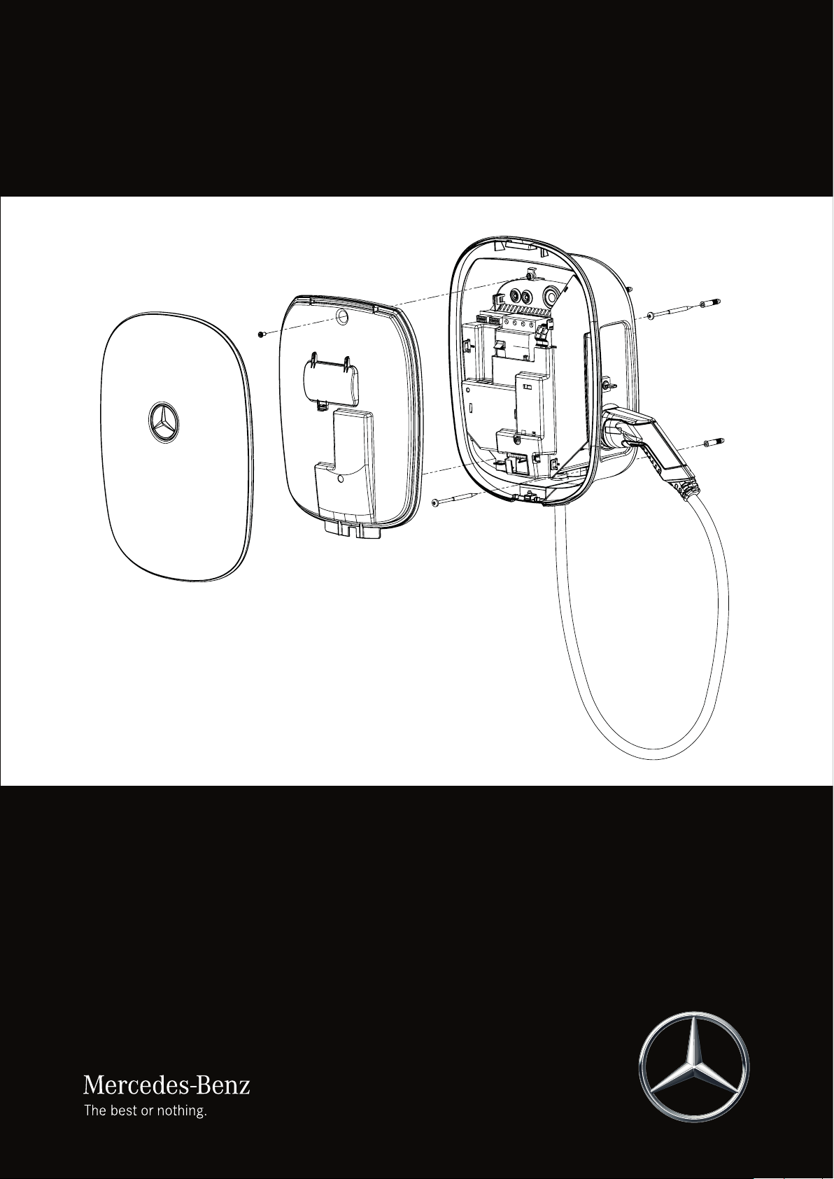
Structure of the Mercedes-Benz Wallbox Home
The Mercedes-Benz Wallbox Home consists of the following:
1 2
3
Housing cover
1
Detachable outer plastic cover to be fixed to the housing base using hanging lip (upper edge) and locked using lockable screw
(lower edge)
Electronic components cover
2
Internal cover for electronic module with integrated flap for manual access to the RCCB (residual current circuit breaker).
Housing base
3
Base with integrated electronic module, fixed charging cable with Type 2 charging plug and charging plug storage holder
6
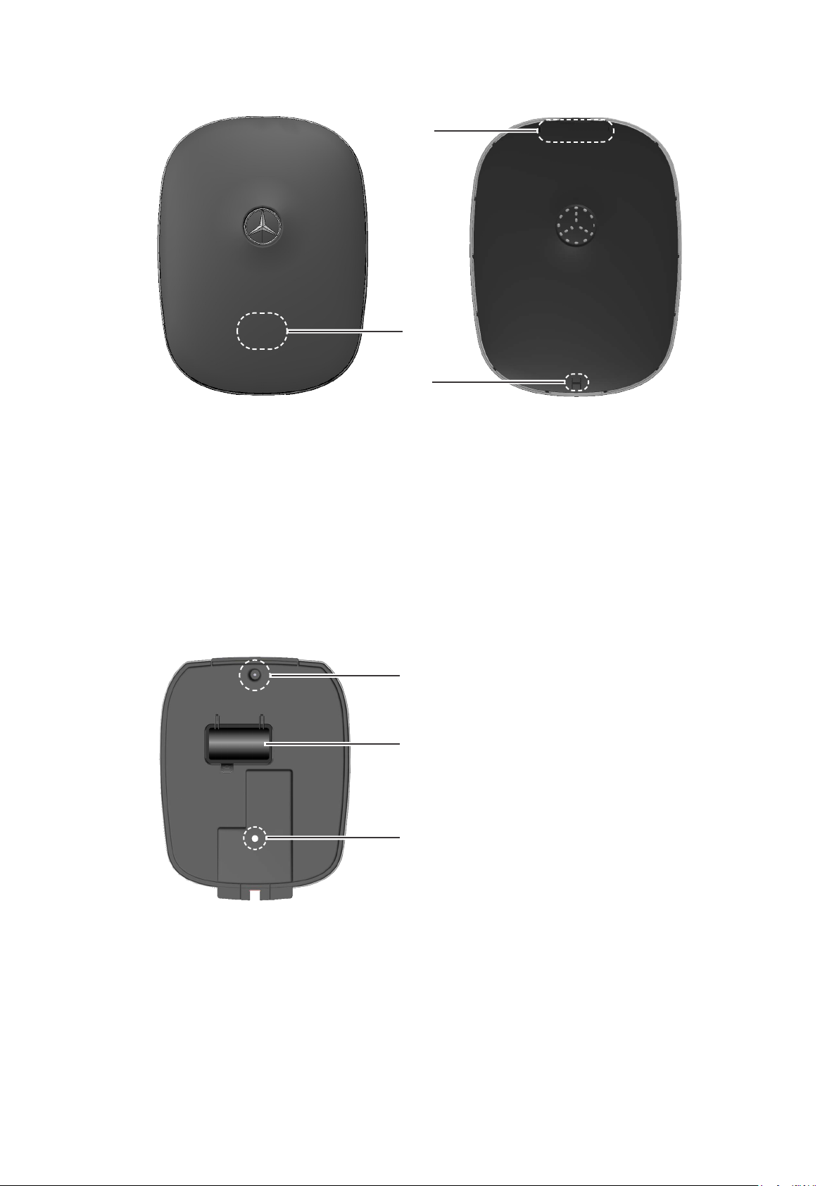
Housing cover (detail)
Front view
Rear view
4
5
6
Plastic lip and guides
4
The plastic lip is for hanging the housing cover onto the housing base. The two guide pins ensure the correct vertical positioning of the housing cover.
LED zone
5
The multi-colored LED display is located in this part of the housing cover.
Locking slot
6
The locking slot is for locking the housing cover to the housing base using the lockable screw.
Electronic components cover (detail)
Front view
7
8
9
Opening for M4 fixing screw
7
This opening is used to fix the electronic components cover to the housing base with a fixing screw (M4 x 10).
RCCB (residual current circuit breaker) access flap
8
This flap provides access to the internal RCCB of the Wallbox.
Lens for multi-colored LED display
9
The multi-colored LED display is shown through this lens.
Mercedes-Benz Wallbox Home| Introducing the product
7

Housing base (detail)
Housing cover slot
0
Front view
Rear view
0
q
w
u
e
r
i
t
o
y
The plastic lip of the housing cover
Grommets for data cables
q
These grommets seal the openings for data cables in the terminals area of the housing base. Connecting data cables is possible e.g. in conjunction with a Mercedes-Benz Wallbox Advanced. Please see the relevant information on connections in the
installation manual for the Mercedes-Benz Wallbox Advanced, available at:
www.yourwallbox.de/downloads/Mercedes-Benz/Advanced/
Power supply grommet
w
This grommet seals the opening for the power supply in the terminals area of the housing base.
RCCB (residual current circuit breaker)
e
The RCCB and the adjacent PE terminals are for connecting the power supply.
Opening for coded rotary switch
r
This opening provides access to the coded rotary switch for setting the maximum charge current and to activate set-up and
test modes (see page 21).
Opening for LED display
t
The multi-colored LED display is shown through this opening.
Lockable screw for housing cover
y
This lockable screw is for locking the housing cover. Its key is also included.
is inserted into this slot.
4
Mounting slots
u
The housing base is fixed into position by hooking these two slots onto mounting screws.
Cable guide
i
This cable guide is intended for a surface-mounted power supply cable.
Openings for screw fixings
o
These openings are used to fix the housing base into position with two screws aer it has been hooked onto the mounting
slots u.
8

Preparations, installation and taking into operation
General requirements of the installation site
Your Mercedes-Benz Wallbox Home is an electrical device and is therefore subject to particular requirements for indoor and
outdoor installation. In selecting the installation site, you must consider the following points:
• Observe all local regulations for electrical installations, e.g. regarding fire protection and accident prevention.
• The Wallbox must be installed where it is freely accessible to all authorized users.
• A parking spot must also be planned for in front of the Wallbox so that the vehicle's charging
connector can at all times be reached with the fixed charging cable of the Wallbox.
• The recommended installation height is 120 to 140 cm from the floor to the lower edge of
the housing. This recommendation may be adjusted upwards or downwards depending on
local conditions. Sufficient air circulation must be ensured at the installation site so that the
Wallbox is cooled during operation: Always observe the allowed operating temperatures (see
“Technical specifications” on page 23).
min. 50 cm
• To ensure the safe operation of the Wallbox, minimum clearances of 50 cm must be ob-
served on all sides of the housing.
• The mounting area must have an even surface that provides sufficient stability for installing
the Wallbox.
• The required mounting area for the Mercedes-Benz Wallbox Home is at least 440 x 330mm
(H x W). The entire rear surface of the Wallbox must be in contact with the mounting surface.
• In general, the Mercedes-Benz Wallbox Home is engineered for operation in high ambient
temperatures. However, it must always be ensured that the maximum operating temperature is not exceeded through external influences such as direct sunlight or similar.
• The Wallbox meets the requirements for outdoor installation. Outdoors, it is recommended that the Wallbox is only installed
in a covered location that provides sufficient protection from the weather.
120 to
140cm
Requirements for the power supply cable
The following standards must always be taken into account for the electrical installation of the Mercedes-Benz Wallbox Home:
• All regulatory requirements for low voltage installations according to IEC 60364-1 and IEC 60364-5-52 apply.
• The A0009067408 model variant is intended for connection to and operation on rated voltages of 230V (phase-neutral,
single phase) or 400V (phase-phase, 3-phase) and 50Hz. The A0009067508 model variant is designed for connection to
and operation on a rated voltage of 230V (phase-neutral, single phase) and 50Hz.
• The installation site must offer a sufficiently dimensioned power supply cable according to HD 60364-7-722:2012: This
power supply must be reserved exclusively for the Wallbox and must not be used to supply other electrical devices.
• If necessary, a separate power supply must be installed that is intended exclusively for connecting the Wallbox and com-
plies with the general requirements for cabling and building infrastructure.
Mercedes-Benz Wallbox Home| Preparations, installation and taking into operation
9

• Depending on the desired rated power, the installation of the Wallbox may need to be registered with and/or approved by
the local electricity grid operator before the device is taken into operation. Please consult the regulations of your local
electricity grid operator.
• Cable dimensions must be adjusted according to the desired rated power and other
aspects (such as cable length, material, cabling method etc.). The terminal blocks in the
Wallbox are designed for cable dimensions from 1.5mm2 to 16mm2.
• The power supply cable may be installed above or below the wall surface. If the power
supply cable is installed above-surface, a cable guide is provided at the back of the housing to guide the cable to the terminals area of the housing base.
• The power supply for the Wallbox must always be protected by its own MCB (rated cur-
rent depending on the power supply and Wallbox settings, but no more than 32 A). Please
always observe the applicable national requirements regarding the selection of the MCB.
• If you want to take the Wallbox out of operation, switch the upstream domestic MCB and
the internal RCCB to the 0 (OFF) position.
• Please always ensure that the installation requirements listed in this manual are complied with. Disregard or actions to the
contrary may lead to severe, even fatal injury by electric shock. In addition, in case of contravention of the notices given,
the proper operation of the Wallbox cannot be guaranteed.
PLEASE NOTE!
In order to achieve the maximum charging output of the Wallbox, the power supply cable must be dimensioned and
installed for 32 A. The maximum charge current (see “Setup and test modes” on page 15) must also be set to 32 A.
Factory settings are 16A for the A0009067408 and 32A for the A0009067508 model variant.
PLEASE NOTE!
In some countries, the above-mentioned requirements are different from the prerequisites for connecting to the local
power grid. In this case, the Wallbox must be connected in accordance with the respective type of mains power connection for the country of installation. You can find an overview of country-specific mains connection schemes on page 28
in this manual or on the www.yourwallbox.de website via the following link:
www.yourwallbox.de/downloads/documents/Mains_Connection_Schemes_Home_Advanced.pdf
Mechanical and electrical installation
Aer determining the mounting site for the Wallbox, you can begin with mechanical installation. For mechanical installation,
you will need the following components:
• Power drill or cordless drill (not included)
• Drill bit Ø 8 mm, appropriate for the wall material (not included)
• Drilling template for the Wallbox model variants described in this manual (included)
• Torx bit screwdrivers (TX20, TX30) (not included)
• VDE blade screwdrivers (blade thickness and length: 0.5 x 2.5mm, 80mm recommended) (not included)
• Cutter for cutting the rubber grommet to insert the supply cable (not included)
• Four 6 x 60 chipboard screws for fixing the housing base (included)
• If required: Wall plugs suitable for the mounting substrate (included: 8 x 40 nylon wall plugs)
• Spirit level if required (not included)
10

DANGER!
Always observe the 5 golden rules of electrical installation:
1. Cut off all voltage sources
2. Secure all cut-off devices
3. Verify absence of voltage
4. Ground and short-circuit
5. Cover or bar access to adjacent components under voltage
Always deactivate the MCB in the domestic power supply as well as the internal RCCB before starting installation. Also
ensure that the MCB and RCCB cannot be reactivated during installation. Otherwise, there is a risk of severe or even fatal
injury through electric shock!
Proceed as follows to install the Wallbox:
1. Ensure that a sufficiently dimensioned power supply cable is available at the desired installation site. Otherwise, a power
supply cable must be installed especially.
2. Place the drilling template vertically onto the chosen mounting surface:
Use a spirit level if required. Mark the drill holes using the template.
3. Drill the mounting holes as marked (Ø 8mm). Depending on the substrate,
insert the wall plugs supplied for the mounting screws.
4. Use the TX30 screwdriver to insert two of the four 6x60 chipboard
screws included into the two upper drill holes and tighten to a distance of
4mm from the wall.
5. Place the Wallbox onto a work surface and open the lockable screw at
the lower edge of the housing base using the housing cover key provided.
Then flip the housing cover up and remove it.
Note: Protect the housing cover from scratches and other types of external damage. Only remove the protective film from the housing cover as
your last step, immediately before completing installation.
Mercedes-Benz Wallbox Home| Preparations, installation and taking into operation
11

6. In the upper part of the Wallbox, use the TX20 screwdriver to loosen the
M4 screw, which is used to fix the internal electronic components cover to
the housing base, and remove the electronic components cover. Keep the
screw in a safe place.
7. Make a cut into the membrane of the largest grommet w: Now insert the
supply cable through this opening.
Note: The two smaller openings sealed with grommets q are needed for
connecting with an external charge control module, e.g. via the MercedesBenz Wallbox Advanced. Please see the relevant information on connections in the installation manual for the Mercedes-Benz Wallbox Advanced,
available at:
www.yourwallbox.de/downloads/Mercedes-Benz/Advanced/
8. Hang the housing base of the Wallbox at the installation site. There are
two integrated screw slots u in the upper part of the back of the housing
base to fit over the screws installed in step 4. The Mercedes-Benz Wallbox
Home is now preinstalled at the installation site.
9. Using the TX30 screwdriver, fix the housing base in place by inserting the
two remaining chipboard screws included through the two openings o
in the lower part of the housing base into the wall plugs installed in step
3 and tightening. The Mercedes-Benz Wallbox Home is now fixed to the
mounting surface.
10. If using a power supply cable with flexible conductors, ensure that the
stripped ends (12mm recommended) are fitted with wire end ferrules.
Loosen the terminal blocks of the internal RCCB, insert the power supply
conductors into their respective terminals and tighten with a torque of 2.5
to 3Nm. The wiring sequence is shown in the following diagram and table.
When tightening terminal L1, always ensure the correct position of the
factory installed conductor!
Operate the spring loaded mechanism of the PE terminal and attach the
protective PE conductor of the power supply cable here.
12

L1L2L3 N
PE
The supply cable for the three-phase model variant A0009067408 must be connected as follows:
Designation Conductor color Connection coding
Phase 1 current-carrying conductor Brown 5 (L1)
Phase 2 current-carrying conductor Black 3 (L2)
Phase 3 current-carrying conductor Gray 1 (L3)
Neutral Blue N
Protective earth Green-Yellow PE
The supply cable for the single-phase model variant A0009067508 must be connected as follows:
Designation Conductor color Connection coding
Current-carrying conductor Brown 5 (L1)
Neutral Blue N
Protective earth Green-Yellow PE
DANGER!
Please note that the electronic components of your Wallbox will be damaged if you apply a voltage above 250V between
the L1 current-carrying conductor and neutral.
PLEASE NOTE!
If desired, the 3-phase model variant A0009067408 can also be connected and operated on a single phase at terminal 2
(L1): However, in this case the rated output for the Wallbox will not be achieved.
In case of an unbalanced load on the supply grid, please observe the technical requirements for installation in force locally. The Mercedes-Benz Wallbox Home is equipped with a symmetry monitoring function that can be activated using the
coded rotary switch. Please find additional information in section “Setup and test modes” on page 15.
PLEASE NOTE!
In some countries, the requirements mentioned in this manual differ from the prerequisites for connecting to the local
power grid. In this case, the Wallbox must be connected in accordance with the respective type of mains power connection for the country of installation. You can find an overview of country-specific mains connection schemes on page 28
in this manual or on the www.yourwallbox.de website via the following link:
www.yourwallbox.de/downloads/documents/Mains_Connection_Schemes_Home_Advanced.pdf
Mercedes-Benz Wallbox Home| Preparations, installation and taking into operation
13

PLEASE NOTE!
Factory settings for the Mercedes-Benz Wallbox Home are for maximum charging currents of 16A (A0009067408 model
variant) and 32A (A0009067508 model variant). Should the charging current made available by your domestic power supply or the supply cable itself differ from these settings, the charge current settings must be adjusted accordingly inside the
Wallbox before you replace the electronic components cover and then take the Wallbox into operation. This is described in
detail in section “Setup and test modes” on page 15 and following.
Please note that the rated current indicated on the product label and configured in the firmware must under no circumstances be exceeded.
11. Replace the electronic components cover inside the housing base and
fix it into place with its M4 x 10 screw.
12. Hook the housing cover onto the upper edge of the housing base and
lock it using the housing cover key provided.
Note: Before you replace the housing cover, you must complete the process of taking the Mercedes-Benz Wallbox Home into operation – please
read the following section for information on this topic.
Taking the Wallbox into operation
Aer mechanical and electrical installation, you must check the correct functioning of the Mercedes-Benz Wallbox Home for
operation and resolve any errors.
Proceed as follows to take the Mercedes-Benz Wallbox Home into operation:
1. Switch on the upstream MCB in your domestic power distribution.
2. Open the access flap 8 in the internal electronic components cover and also switch on the internal RCCB (the Wallbox is
connected to the electricity grid).
When the Wallbox is connected to the electricity grid, it will initiate the start-up procedure: This includes a test of the internal
electronic components to ensure correct functioning.
The internal check routine is indicated by the LED display on the front of the Mercedes-Benz Wallbox Home as follows.
LED display Description
The LED flashes white once ...
... and then pulsates blue.
The vehicle can now be connected for charging. Initiating and terminating charging procedures is described in detail in the
quick start guide included, as well as in the comprehensive operating manual for the Mercedes-Benz Wallbox Home: You can
download the comprehensive operating manual at www.yourwallbox.de/downloads/Mercedes-Benz/Home/. Please also
refer to the operating manual of the vehicle to be charged at the Wallbox.
Aer the Mercedes-Benz Wallbox Home has been properly taken into operation, replace the housing cover and lock it into
place: This is described in step 12 above.
14

PLEASE NOTE!
To finalize the process of taking the Wallbox into operation, the maximum charge current setting of the power supply must
be checked inside the Wallbox and adjusted if required using the coded rotary switch. In order to perform a final check
of the functioning of the Wallbox, the contactor of the Wallbox must be checked in test mode for correct functioning. Test
mode is described in the next section.
Setup and test modes
If no vehicle is available for taking the Wallbox into operation or for testing it, you can check the functioning of the MercedesBenz Wallbox Home (contactor, CP and RCD tripping) using test mode. You can also alter the factory setting for the maximum
charging current of the Mercedes-Benz Wallbox Home in setup mode using the coded rotary switch if the charge current
made available by the domestic power supply differs from this preset value. However, the rated current indicated on the product label must not be exceeded under any circumstances.
The electronic components module of the Mercedes-Benz Wallbox Home provides access to the coded rotary switch, which is
factory preset to the 0 position, through the opening on the le
hand side.
For test and setup mode, you can set the coded rotary switch
to one of the values indicated on the cover around the opening
using the VDE blade screwdriver (0.5 x 2.5mm). You can find an
explanation of these values in section “Settings for the coded
rotary switch” on page 17.
In order to adjust the settings using the coded rotary switch, you
must remove the housing cover and, depending on the working
step, remove or replace the electronic components cover (see
steps 5 and 6 described on page 11 in section “Mechanical
and electrical installation”).
4
5
3
6
I
I
I
2
I
7
I
I
1
I
8
I
I
0
I
9
I
F
I
I
A
I
I
I
E
B
D
C
DANGER!
After opening the electronic components cover, dangerous voltages may be present on the inside of the Wallbox as well as
on components you are able to touch. ALWAYS switch off the MCB in the domestic power supply and the internal RCCB of
the Wallbox before you continue in setup or test mode.
Always observe the 5 golden rules of electrical installation:
1. Cut off all voltage sources
2. Secure all cut-off devices
3. Verify absence of voltage
4. Ground and short-circuit
5. Cover or bar access to adjacent components under voltage
Otherwise, there is a risk of severe or even fatal injury through electric shock!
Test mode
Proceed as follows to check the functioning of the Mercedes-Benz Wallbox Home in test mode:
Working step Status of LED display
1. Switch off the power supply for the Wallbox via the upstream MCB and the internal
RCCB.
2. Remove the internal electronic components cover. Set the coded rotary switch to position E (see table on page 17).
Mercedes-Benz Wallbox Home| Preparations, installation and taking into operation
15

Working step Status of LED display
3. Replace the internal electronic components cover. Switch on the power supply for the
Wallbox via the upstream MCB and the internal RCCB.
4. The Wallbox will now start up in test mode. In test mode, the charge current is limited
to 6 A.
5. First, the Wallbox will perform an automated internal check.
• If an error occurs during the internal check, the LED will display error code F2:
Please also see the description on page page 19.
• If the internal check does not return an error, continue with step 6.
DANGER!
During test mode, dangerous currents are applied to the charging contacts of the Wallbox, which present a danger to life
and limb: Do not touch these contacts under any circumstances and proceed with the following actions using extreme
caution. Otherwise, there is a risk of severe or even fatal injury through electric shock!
Working step Status of LED display
6. In test mode, you can measure the voltages at the charging plug for 120seconds (see
“Wiring sequence Type 2” on page 25). Measuring the CP contact signal (frequency
and duty cycle, measurement against PE) is also possible. After 120seconds, the charging function is locked and the internal RCCB will trip.
7. To terminate test mode, switch off the power supply of the Wallbox via the upstream
MCB and switch the RCCB to the 0 position.
8. Remove the internal electronic components cover. Set the coded rotary switch to either
the 0 or F position (factory settings for normal charging operations), or to another position if you intend to operate the Wallbox on a charging current different from the factory
setting (see table on the next page).
9. Replace the internal electronic components cover. Switch the RCCB to the I position.
Replace and lock the housing cover.
10. Switch on the power supply for the Wallbox via the upstream MCB in the domestic power
distribution.
11. During start-up, the Wallbox will upload the setting of the coded rotary switch and then
work using the charging current set by the switch.
Setup mode
120 seconds
Please follow these steps to change the maximum charging current setting of your Mercedes-Benz Wallbox Home:
Working step Status of LED display
1. Switch off the power supply for the Wallbox via the upstream MCB and the internal
RCCB.
2. Remove the internal electronic components cover. Select the desired charge current by
setting the coded rotary switch to the respective position (see table on the next page).
3. Replace the internal electronic components cover. Switch the RCCB to the I position.
Replace and lock the housing cover.
4. Switch on the power supply for the Wallbox via the upstream MCB in the domestic power
distribution.
16

Working step Status of LED display
5. During start-up, the Wallbox will upload the setting of the coded rotary switch and then
work using the charging current set by the switch.
Settings for the coded rotary switch
The following settings can be selected using the coded rotary switch:
Position Description Explanation
0 Normal operations Factory setting
1
2 10 A
3 13 A
4 16 A
5 20 A
6 20 A with 16 A imbalance detection
7 30 A
8 30 A with 16 A imbalance detection
9 30 A with 20 A imbalance detection
A 32 A
B 32 A with 16 A imbalance detection
C 32 A with 20 A imbalance detection
D no function -
E Test mode
F Normal operations Factory setting
Setting the maximum charge current
8 A
Measuring voltage (contactor closed) and communications (CP) possible at the charging contacts in order
to test functionality without a vehicle
Mercedes-Benz Wallbox Home| Preparations, installation and taking into operation
17

Error detection and solutions
Should a malfunction occur during operation of the Mercedes-Benz Wallbox Home, this is shown by the multi-colored LED
display in the lower part of the housing cover as an error code. The LED may ...
... flash in a range of colors
... pulsate and flash in a range of colors
The following chapter describes how you recognize malfunctions as well as error states, and which measures you can take to
resolve them.
Operational malfunctions and solutions
For safe operation, the Mercedes-Benz Wallbox Home must be protected by an MCB in the domestic power supply in addition
to the internal RCCB. To take suitable measures and restore operation in case of malfunction, you must first clearly identify
the type of error. The following errors may occur:
Type of error Possible cause Suggested solution
The power supply is interrupted: Check the upstream MCB and the internal RCCB and switch them
back on if required. If the error repeats or occurs permanently, contact your local Mercedes-Benz
technical support.
Check your mains connection scheme using the overview of country-specific mains connection
schemes on page 28 in this manual or on the www.yourwallbox.de website via the following link:
www.yourwallbox.de/downloads/documents/Mains_Connection_Schemes_Home_Advanced.
pdf
If necessary, change your mains connection scheme according to this overview.
The Wallbox must be replaced. In this case, please always contact your local Mercedes-Benz technical
support.
Remove the charging plug from the vehicle and plug it back in: Should the error persist, check the
charging cable for damage and contact your local Mercedes-Benz technical support.
You can find further information on error codes in the following section. Please re-initiate the charging
procedure: If the error repeats or occurs permanently, take the Wallbox out of operation (see “Taking
the product out of and back into operation” on page 22) and switch off the upstream MCB. Contact
your local Mercedes-Benz technical support.
The LED is not functioning.
The electric vehicle is not
recognized.
The LED shows an error
code.
The Wallbox does not have a
power supply.
The Wallbox has not been
connected in accordance
with the respective type of
mains power connection for
the country of installation.
An internal fault has occurred in the Wallbox.
The charging cable is not
plugged into the vehicle
properly.
The Mercedes-Benz Wallbox
Home detects a malfunction.
PLEASE NOTE!
Should the power supply be faulty, please take the Wallbox out of operation (see “Taking the product out of and back into
operation” on page 22) and switch off the upstream MCB. Contact Mercedes-Benz technical support or your installation
service provider.
18

Error codes and solutions
To represent different error states, the multicolor LED will flash in a specific, repeating pattern. You can find the correlations
between visual display and errors in the following list:
Display Description
Die LED flashes red once and then green four
times.
Solution: The Wallbox will switch off the RCCB inside the Wallbox 20seconds aer detecting the error. Switch the power supply back on via the RCCB inside the Wallbox (see “Checking the internal RCCB” on page 21).
If this error repeats or persists, an internal malfunction has occurred and the Wallbox must be replaced. Take the Wallbox out
of operation (see “Taking the product out of and back into operation” on page 22) and contact your local Mercedes-Benz
technical support.
Display Description
The LED flashes red once, green three times and
then blue once.
Solution: Switch the power supply off and then back on again. If this error repeats or persists, an internal malfunction has
occurred and the Wallbox must be replaced. Take the Wallbox out of operation (see “Taking the product out of and back into
operation” on page 22) and contact your local Mercedes-Benz technical support.
Display
Error F1: The main contactor of the Wallbox does not open.
Error F2: The Wallbox has detected an internal malfunction.
Description
Error F3: The internal DC fault current module has detected a DC fault
The LED flashes red once and then alternates
twice between green and blue.
Solution: If the error occurs for the first time, the charging procedure is interrupted for 30 seconds and then restarted automatically. If the error occurs again immediately, the charging procedure is terminated permanently: a new charging procedure
is only possible aer disconnecting the vehicle from the Wallbox.
If the error repeats, it is possible that an electrical fault has occurred in the charging system of the vehicle or that the Wallbox
must be checked. Do not charge the vehicle and immediately contact your local Mercedes-Benz technical support. In addition, always consider the notices provided in the operating manual of the vehicle.
Display Description
The LED flashes red once, green once and then
blue three times.
Solution: Switch the power supply off and then back on again. If this error repeats or persists, an internal malfunction has
occurred and the Wallbox must be replaced. Take the Wallbox out of operation (see “Taking the product out of and back into
operation” on page 22) and contact your local Mercedes-Benz technical support.
current.
Error F4: The Wallbox has detected an internal malfunction.
Mercedes-Benz Wallbox Home| Error detection and solutions
19

Display Description
Error F7: The vehicle demands a charging procedure with ventilation.
The LED flashes red once and then blue twice.
Solution: The Wallbox automatically reinitiates the charging procedure every 60seconds. If the error continues to occur,
please contact your local Mercedes-Benz technical support. Charging vehicles that require ventilation during the charging
procedure is not possible with the Mercedes-Benz Wallbox Home.
Display
Description
Error F8: A short circuit has been detected between the pilot contact
CP and the protective earth PE, or the communication interface of the
The LED flashes red once and then green twice.
vehicle is faulty.
Solution: The Wallbox automatically reinitiates the charging procedure every 60seconds. If the error continues to occur,
check the charging cable for external damage. If the cable does not show signs of damage, the vehicle and the Wallbox must
be checked: Please contact your local Mercedes-Benz technical support.
Display Description
Error F9: The electrical current monitoring module has detected that
The LED flashes red once, green three times
the charging current is exceeding the preset maximum current.
and then yellow once.
Solution: The Wallbox automatically reinitiates the charging procedure every 60seconds. If the error continues to occur, the
vehicle and the Wallbox must be checked: Contact your local Mercedes-Benz technical support.
Display Description
Error F10: The temperature monitor has detected a temperature above
The LED flashes red once, green twice and then
80° Celsius inside the housing.
yellow twice.
Solution: The temperature monitor interrupts the charging procedure.
• After 10minutes, the charging procedure is automatically reinitiated if the temperature inside the housing has fallen to
below 70°Celsius.
• The charging procedure is reinitiated immediately as soon as the temperature inside the housing falls to below 60° Celsius.
If the error repeats or persists, the Wallbox must be cooled and/or shaded more effectively at the installation site. If the error
repeats or persists, the Wallbox must be checked and replaced if required: Contact your local Mercedes-Benz technical support.
Display Description
The LED flashes red once, green once and then
Error F11: The contactor inside the Wallbox doesn't close.
yellow three times.
Solution: The Wallbox automatically reinitiates the charging procedure every 60seconds. If the error occurs for a second
time, the charging procedure is reinitiated aer 10minutes. If this error repeats or persists further, an internal malfunction
has occurred and the Wallbox must be replaced. Take the Wallbox out of operation (see “Taking the product out of and back
into operation” on page 22) and switch off the upstream MCB. Contact your local Mercedes-Benz technical support.
20

Display Description
Error F15: Current monitoring has detected that the preset maximum
load imbalance has been exceeded and has reduced the maximum
The LED pulsates green and flashes blue once.
Solution: Charging operations may continue, but the charging output will be reduced. If the error repeats, it is possible that a
fault has occurred in the charging system of the vehicle or that the maximum load imbalance setting must be checked. Contact your local Mercedes-Benz technical support if required. In addition, always consider the notices provided in the operating
manual of the vehicle.
Display Description
The LED pulsates green and flashes red once.
Solution: Charging operations may continue, but the charging output will be reduced. If this error repeats or persists, an internal malfunction has occurred and the Wallbox must be replaced. Take the Wallbox out of operation (see “Taking the product
out of and back into operation” on page 22) and switch off the upstream MCB. Contact your local Mercedes-Benz technical
support.
Display Description
The LED pulsates green and flashes red once.
charging current.
Error F16: Data transfer to the integrated electrical current monitor is
disrupted. The maximum charging current is limited to 10A while this
error occurs.
Error F17: The temperature monitor has detected a temperature above
60° Celsius inside the housing. The maximum charging current will be
limited to 6A.
Solution: Charging operations may continue, but the charging output will be reduced. If the error repeats or persists, the
Wallbox must be cooled and/or shaded more effectively at the installation site. If the error repeats or persists, the Wallbox
must be checked and replaced if required: Contact your local Mercedes-Benz technical support.
CAUTION!
If the Wallbox continues to or permanently displays error messages, take the Wallbox out of operation (see “Taking the
product out of and back into operation” on page 22) and contact your local Mercedes-Benz technical support. Repairs
may have to be carried out before charging procedures can resume.
Checking the internal RCCB
To ensure the continuing safe operation of the Wallbox, you must manually test the function of the internal RCCB every
6months: The RCCB has a button with which to initiate the test function.
PLEASE NOTE!
The internal DC fault current detection conducts a self-test before each charging procedure: a manual check is not required. In case of an error, the LED display will show an error code (see also from page 18).
Proceed as follows to test an RCCB:
1. While the Wallbox is ready for operation, remove the housing cover using the key included.
2. Open the flap for the internal safety switches in the electronic components cover.
3. Locate the button engraved T or marked Test.
4. Press the button: The RCCB must now trip and flick its pivot lever into the center position (connection to the power supply
is interrupted).
5. Now switch the RCCB off completely (0 position) and then back on by flicking the pivot lever up into the I position.
6. Close the flap, replace the housing cover and lock it using the key.
Mercedes-Benz Wallbox Home| Error detection and solutions
21

DANGER!
Should the RCCB not trip during testing (pivot level in center position), you must not continue to operate the Wallbox under
any circumstances! Take the Wallbox out of operation and please contact your local Mercedes-Benz technical support.
Taking the product out of and back into operation
If required, you can take your Mercedes-Benz Wallbox Home out of operation. To take the Wallbox out of operation, please
proceed as follows:
1. Switch off the upstream MCB (connection to the electricity grid is interrupted).
2. Open the housing cover of the Wallbox, open the access flap in the electronic components cover and flick the pivot lever
of the RCCB into the 0 (OFF) position.
3. Always observe the five golden rules of electrical installation!
Now, no charging procedure can be carried out with the Mercedes-Benz Wallbox Home and it can be uninstalled by a qualified
electrical contractor if required. If you do not want to uninstall the Wallbox, replace the housing cover by hooking it onto the
upper edge of the housing base and lock it using the key provided.
To take the Wallbox back into operation at a later time, please proceed as follows:
1. Remove the housing cover of the Wallbox, open the access flap in the electronic components cover and flick the pivot
lever of the RCCB into the I position.
2. Close the access flap. Hook the housing cover onto the upper edge of the housing base and lock it using the housing
cover key provided.
3. Switch on the upstream MCB.
When the Mercedes-Benz Wallbox Home is reconnected to the electricity grid, it will initiate the start-up procedure: As described in section “Taking the Wallbox into operation” on page 14 , the vehicle can now be connected for charging.
Returning your Wallbox
Should your Wallbox display error messages permanently during installation or subsequent operation, or if it does not function properly, contact your local Mercedes-Benz technical support. If the error can still not be resolved, the Wallbox must be
replaced. For this purpose, you must take the Wallbox out of operation, have a qualified electrical contractor uninstall it and
return it via Mercedes-Benz technical support for repairs.
In addition to the Wallbox itself, you must fill in and include the 'Checklist for returns' document with the parcel. Please
ensure that the data entered in the document are correct and complete, and that the document has been signed by the customer as well as the installing technician. Otherwise the Wallbox cannot be replaced.
You can find the 'Checklist for returns' document on the www.yourwallbox.de website via this link:
www.yourwallbox.de/downloads/documents/RMA_document_Home_Advanced.pdf
22

Appendix
Technical specifications
Model variant A0009067408 A0009067508
Compliance IEC 61851-1 / 61439-7
Grid connection for supply cable sizes of up to 5 x 16 mm² for supply cable sizes of up to 3 x 16 mm²
Rated voltage 230 / 400 V 230 V
Rated current 32 A, single or 3-phase 32 A, single phase
Rated frequency 50 Hz
Max. output 22 kW 7.2 kW
Charging connection Fixed charging cable with charging plug according to IEC 62196-2 Type 2, ca. 6 m
Circuit-protection devices Type A 30 mA RCCB and DC-RCM, I
Control / Customization
Upstream fuse C characteristic MCB, rated current according to power supply and Wallbox setting but no more than 32 A
Factory setting for maximum charging current 16 A 32 A
PE system TN-S
Operating temperature -30 to 50°C
Storage temperature -30 to 85°C
Relative humidity 5 to 95% (no condensation)
Class of protection I
Overvoltage category III
Degree of pollution 3
Rated insulation voltage (Ui) 4kV
Rated impulse voltage (U
Rated peak withstand current (Ipk) 6kA
Rated short-time withstand current (Icw) 5kA
Rated conditional short-circuit current (Icc) 6/10 kA (C tripping characteristic)
) 4kV
imp
Internal RS485 interface (interface for external load management,
no access for users/installation technicians)
electronic DC fault current detection ≥ 6 mA
Δn d.c.
Rated diversity factor (RDF) 1.0
Degree of protection (housing) IP 55
Impact strength IK08
Dimensions (housing) 438 x 328 x 170 mm (H x W x D)
Maximum elevation ≤ 2,000 m AMSL (above mean sea level)
Weight per unit (net) ca. 8.5 kg
Weight per unit (gross) ca. 10 kg
Mercedes-Benz Wallbox Home| Appendix
23

Scale drawings and dimensions
328
438
170
328
170
438
193
227,7
The Mercedes-Benz Wallbox Home is delivered fully assembled and checked. The following scale drawings show the housing
dimensions as well as the distances for the screw slots required for installation.
Wall box with fixed charging cable
Plan and elevation (all dimensions in mm)
Rear view (housing base, all dimensions in mm)
193
24

Wiring sequence Type 2
PE
CS
L2/N
PE
CP
L1
CP
N
L3
PP
L1
L2
Guidelines & Norms
The Mercedes-Benz Wallbox Home complies with the following standards and protection ratings:
General guidelines and laws
Guideline Explanation
2014/35/EU Low voltage directive
2014/30/EU EMC Guideline
2011/65/EU RoHS 2 guideline
2012/19/EU WEEE Guideline
ElektroG Electrical and Electronic Device Statute
Device safety standards
Standard Explanation
IEC 61851-1: 2017 Ed. 3.0 Conductive charging systems for electric vehicles – Part 1: General requirements
IEC/TS 61439-7:2014 Part 7: Switching device combinations for specific applications such as marinas, campgrounds, market
squares, charging stations for electric vehicles
IEC 61000-6-2:2016 Electromagnetic compatibility (EMC) - Part 6-2: Generic standards - immunity standard for industrial environ-
ments
IEC 61000-6-3:2006+AMD1:2010 Electromagnetic compatibility (EMC) - Part 6-3: Generic standards - Emission standard for residential, com-
mercial and light-industrial environments
IEC 61000-6-7:2014 Electromagnetic compatibility (EMC) - Part 6-7: Generic standards - Immunity requirements for equipment
intended to perform functions in a safety-related system (functional safety) in industrial locations
IEC 61851-21-2: 2018 Ed. 1.0 Conductive charging systems for electric vehicles – Part 21-2: EMC requirements for off board electric vehicle
charging systems
Mercedes-Benz Wallbox Home| Appendix
25

Classes of protection & degrees of protection
DC
DC-RCM
LED
MCB
NHN
RCCB
Class of protection /
degree of protection
IP 55
Explanation
The device complies with IEC protection class 1.
Degree of protection: complete protection against touch, protection against dust in harmful quantities and
against light water jets from any angle (DIN EN 60529: 2014-09)
CE certification and compliance declaration
The Mercedes-Benz Wallbox Home carries the CE mark. The associated declaration of compliance is available
for download in electronic format at
www.yourwallbox.de/downloads/documents/Declaration_of_Conformity_Home_Advanced.pdf.
Glossary & Definitions
In the following, important abbreviations and terms used in this manual are explained.
Abbreviation Explanation Meaning
Direct Current Direct current
Direct Current Residual Current Monitor Monitoring device for detecting DC fault currents
Light Emitting Diode Light-emitting diode
Miniature Circuit Breaker Miniature circuit breaker
Normalhöhennull Reference plain for height above sea level (AMSL)
Residual Current Circuit-Breaker Fault current circuit breaker
Trademarks
All trademarks mentioned in this manual, including those that may be protected by third parties are, without restriction,
subject to the regulations of the respectively applicable trademark law and the property rights of the respective registered
owners.
All trademarks, trading names or company names marked here as such are or may be trademarks or registered trademarks of
their respective owners. All rights not explicitly granted here are reserved.
The absence of explicit identification of trademarks used in this manual must not lead to the conclusion that a name is free
from the rights of third parties.
26

Intellectual Property & Copyright
Copyright © 2019
Version 1.2, MB-IM_Home-2019-12-15
All rights reserved.
Any information in this manual may be changed without prior notice and does not represent any obligation on the part of the
manufacturer.
Illustrations in this manual may show designs different from the delivered product and do not represent any obligation on the
part of the manufacturer.
The manufacturer does not take responsibility for any losses and/or damages that occur because of the data or possible
misinformation contained in this manual.
This manual, in its entirety or in parts, must not be reproduced, stored electronically or otherwise transmitted electronically,
electrically, mechanically, optically, chemically, by photocopy or as an audio recording without the written permission of the
manufacturer.
Disposal advice
For the preservation and protection of the environment, the prevention of pollution and in order to
improve the recycling of resources, the European Commission has issued a guideline (WEEE-Guideline
2012/19/EC and EAG-VO) according to which electrical and electronic devices are taken back by the
manufacturer in order to have them properly disposed of or recycled.
Therefore, devices marked with this symbol may not be disposed of as part of unsorted domestic
waste inside the European Union: please inquire with your local authorities regarding proper disposal.
The materials are recyclable as marked. By re-using, recycling or through other forms of processing
obsolete devices, you make an important contribution to environmental protection.
Mercedes-Benz Wallbox Home| Appendix
27

Mains Connection Schemes
Country
Local
frequency
Local voltage
(domestic applications)
Phase L1 Phase L2 Phase L3 Neutral 1-ph 3-ph
New Zealand 50Hz 230 / 400V
L1 L2 L3 N x
L1 N x
Oman 50 Hz 240 / 415 V L1 L2 L3 N x
Pakistan 50 Hz 230 / 400 V L1 L2 L3 N x
Panama 60 Hz 120 / 240 V L1 L2 x
Philippiness 60 Hz 220 / 380 V L1 L2 x
Qatar 50 Hz 240 / 415 V L1 L2 L3 N x
Saudi Arabia 60 Hz 230 / 400 V L1 N x
Serbia 50 Hz 230 / 400 V L1 L2 L3 N x
Singapore 50 Hz 230 / 400 V L1 L2 L3 N x
South Africa 50 Hz 220 - 250 / 380 - 433 V L1 L2 L3 N x
South Korea 60 Hz 220 / 380 V L1 N x
Sri Lanka 50 Hz 230 / 400 V L1 L2 L3 N x
Taiwan 60 Hz 110 / 220 V L1 L2 x
Thailand 50 Hz 220 / 380 V L1 L2 L3 N x
Turkey 50 Hz 230 / 400 V
L1 N x
L1 L2 L3 N x
Ukraine 50Hz 230 / 400V L1 L2 L3 N x
United Arab Emirates 50 Hz 230 / 400 V L1 L2 L3 N x
Uruguay 50 Hz 230 / 400 V L1 L2 L3 N x
Vietnam 50 Hz 220 / 380 V L1 L2 L3 N x
Region Country
Local
frequency
Local voltage
(domestic applications)
Phase L1 Phase L2 Phase L3 Neutral 1-ph 3-ph
"Europe
(without Norway and UK)"
50 Hz 230 / 400 V
L1 N x
L1 L2 L3 N x
Norway 50 Hz
230 V L1 L2 x
L1 L2 N x
UK 50 Hz 240 / 415V L1 N x
Country
Albania 50Hz 230 / 400V L1 L2 L3 N x
Argentina 50Hz 220 / 380V L1 L2 L3 N x
Australia 50Hz 230 / 400V
Azerbaijan 50Hz 220 / 380V L1 L2 L3 N x
Bahrain 50 Hz 230 / 400 V L1 L2 L3 N x
Bangladesh 50 Hz 220 / 440 V L1 L2 L3 N x
Bosnia an Herzegovina 50 Hz 230 / 400 V L1 L2 L3 N x
Brazil 60 Hz 220 / 440 V L1 N x
Cayman Islands 60 Hz 120 / 240 V L1 L2 x
Chile 50 Hz 220 / 380 V L1 L2 L3 N x
China 50 Hz 127 / 220 V L1 L2 x
Colombia 60 Hz 120 / 240 V L1 L2 x
Eurasian Customs Union
(Belarus, Kazakhstan,
Russia)
Ecuador 60 Hz 120 / 220 V L1 L2 x
Egypt 50 Hz 220 / 380 V L1 L2 L3 N x
French Polynesia (Tahiti) 60 Hz 220 / 380 V L1 L2 x
Hong Kong 50 Hz 220 / 380 V L1 L2 L3 N x
India 50 Hz 230 / 400 V L1 L2 L3 N x
Indonesia 50 Hz 230 / 400 V L1 L2 L3 N x
Israel 50 Hz 230 / 400 V L1 L2 L3 N x
Local
frequency
50 Hz 230 / 400 V L1 L2 L3 N x
Local voltage
(domestic applications)
Phase L1 Phase L2 Phase L3 Neutral 1-ph 3-ph
L1 L2 L3 N x
L1 N x
Jamaica 60 Hz 110 / 220V L1 L2 x
Japan 50 / 60 Hz 100 / 200 V L1 L2 x
Jordan 50 Hz 230 / 400 V L1 L2 L3 N x
Kosovo 50 Hz 230 / 400 V L1 L2 L3 N x
Kuwait 50 Hz 240 / 415 V L1 L2 L3 N x
Laos 50 Hz 230 / 400 V L1 L2 L3 N x
Lebanon 50 Hz 230 / 400 V L1 L2 L3 N x
Macau 50 Hz 230 / 400 V L1 L2 L3 N x
Macedonia 50 Hz 230 / 400 V L1 L2 L3 N x
Malaysia 50 Hz 230 / 400 V L1 L2 L3 N x
Mauritius 50 Hz 230 / 400 V L1 L2 L3 N x
Mexico 60 Hz 127 / 220 V L1 L2 x
Montenegro 50 Hz 230 / 400 V L1 L2 L3 N x
Morocco 50 Hz 220 / 380 V L1 L2 L3 N x
28

Country
New Zealand 50Hz 230 / 400V
Oman 50 Hz 240 / 415 V L1 L2 L3 N x
Pakistan 50 Hz 230 / 400 V L1 L2 L3 N x
Panama 60 Hz 120 / 240 V L1 L2 x
Philippiness 60 Hz 220 / 380 V L1 L2 x
Qatar 50 Hz 240 / 415 V L1 L2 L3 N x
Saudi Arabia 60 Hz 230 / 400 V L1 N x
Serbia 50 Hz 230 / 400 V L1 L2 L3 N x
Singapore 50 Hz 230 / 400 V L1 L2 L3 N x
South Africa 50 Hz 220 - 250 / 380 - 433 V L1 L2 L3 N x
South Korea 60 Hz 220 / 380 V L1 N x
Sri Lanka 50 Hz 230 / 400 V L1 L2 L3 N x
Taiwan 60 Hz 110 / 220 V L1 L2 x
Thailand 50 Hz 220 / 380 V L1 L2 L3 N x
Local
frequency
Local voltage
(domestic applications)
Phase L1 Phase L2 Phase L3 Neutral 1-ph 3-ph
L1 L2 L3 N x
L1 N x
Turkey 50 Hz 230 / 400 V
Ukraine 50Hz 230 / 400V L1 L2 L3 N x
United Arab Emirates 50 Hz 230 / 400 V L1 L2 L3 N x
Uruguay 50 Hz 230 / 400 V L1 L2 L3 N x
Vietnam 50 Hz 220 / 380 V L1 L2 L3 N x
Region Country
"Europe
(without Norway and UK)"
Norway 50 Hz
UK 50 Hz 240 / 415V L1 N x
Local
frequency
50 Hz 230 / 400 V
Local voltage
(domestic applications)
230 V L1 L2 x
L1 N x
L1 L2 L3 N x
Phase L1 Phase L2 Phase L3 Neutral 1-ph 3-ph
L1 N x
L1 L2 L3 N x
L1 L2 N x
Mercedes-Benz Wallbox Home|
29

The manufacturer may have made minor technical modifications to the product after publication of this installation manual. This may also have led to minor
discrepancies in the appearance of the product. Any color differences are a result of the printing process.
Mercedes-Benz AG, Mercedesstr. 120, 70372 Stuttgart, Germany
 Loading...