

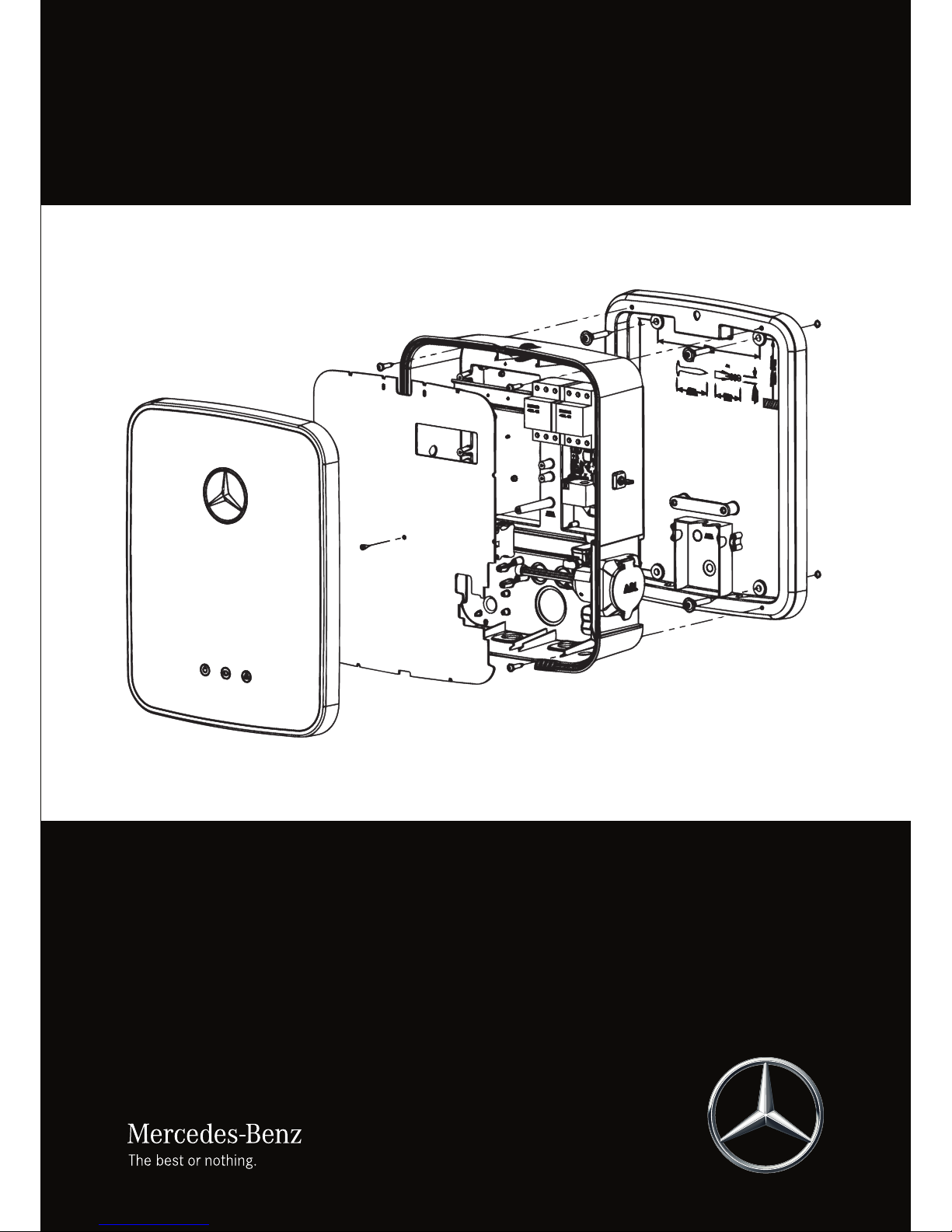
Mercedes-Benz Wallbox
Installation manual for
specialist electrical contractors

ii
Important addresses
Contact
Daimler AG
Mercedesstraße 137
70327 Stuttgart, Germany
In case of technical questions, please contact your local Mercedes-Benz technical support.
This manual, in its entirety or in parts, must not be reproduced, stored electronically or otherwise transmitted electronically,
electrically, mechanically, optically, chemically, by photocopy or as an audio recording without express written permission.
Version 1.1, MB-IM-Wallbox-2017-03-06 Article No. 0301482_c

iii
Mercedes-Benz Wallbox
Contents
Important addresses ii
Important information 1
Preface 1
About this manual 1
Safety notices in this manual 1
Safety notices on the device 2
General safety information 2
General product information 3
Notes regarding installation 4
Preparations, installation and
taking into operation 5
Introducing the product 5
Unpacking and components
included 5
Identifying your model variant 5
General requirements of the
installation site 6
Requirements for the power supply 7
Mechanical installation of the
mounting plate 7
Taking the wallbox into operation 11
Error detection and solutions 13
Disruptions to the operation
of the wallbox and solutions 13
Error codes and solutions 13
Setup and testing modes 16
Taking the product out of and
back into operation 20
Returning your wallbox 20
Appendix 21
Technical specifications 21
Scale drawings and dimensions 22
Contact chart Type 1/Type 2 23
Guidelines & Norms 24
CE certification and
compliance declaration 24
Glossary & Definitions 24
Trademarks 25
Intellectual Property & Copyright 25
Disposal advice 25
Mains Connection Schemes 26

iv

1
Mercedes-Benz Wallbox | Important information
Important information
Preface
This manual describes the mechanical and electrical installation of the Mercedes-Benz Wallbox. The working steps described
in this manual must only be carried out by qualified specialist personnel (mechanical installation) and qualified specialist electrical contractors (electrical installation), who, on the basis of their specialist training, knowledge and experience as well as
their knowledge of the relevant regulations, can assess and carry out the working steps described in this installation manual
and recognize potential hazards.
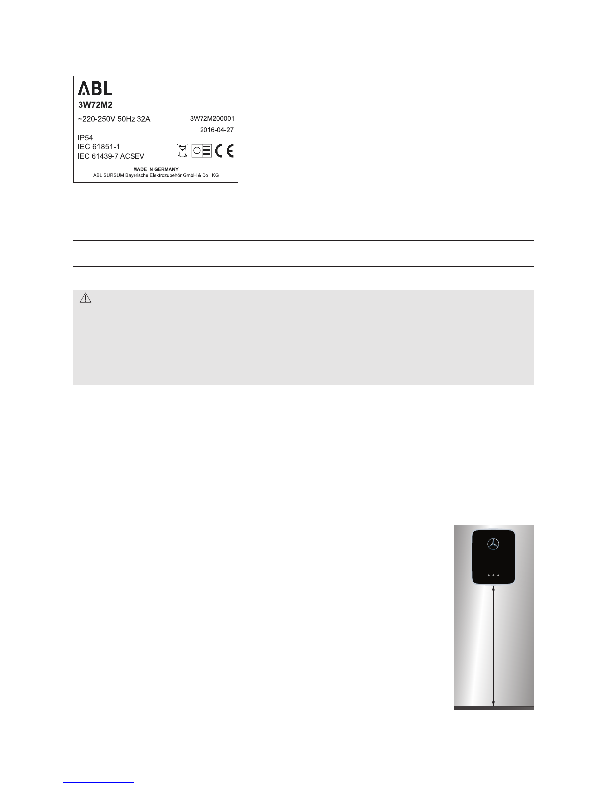
The model variants of the Mercedes-Benz Wallbox can be identified by the product labels on the wallbox. These labels state
the Mercedes-Benz product identification number (exterior underside) as well as the ABL model number (interior electronic
components cover), but are identical regarding technical specifications. Always make sure before installation that your model
variant is the one described in this installation manual!
The following wallbox model variant is the subject of this manual:
Mercedes-Benz product identification number ABL model number
A0009060307 3W72M2
About this manual
This manual is included with the Mercedes-Benz Wallbox and documents the steps and settings required for installing the
wallbox, taking it into operation as well as for resolving malfunctions during operation. For quick and easy reference, certain
sections of this manual are specially formatted.
• Descriptions listing equally valid options (as is the case here) are indicated by bullet points.
• Descriptions that describe performing a function are shown in the form of numerical lists indicating the order of the indi-
vidual working steps.
Please make sure you read this manual carefully and ensure in particular that you follow all safety notices given in this manual.
All measurements in this manual are in millimeters. Where necessary, the scale is indicated for different illustrations.
Please note that all technical details, specifications and design characteristics of the product may be changed without prior
notice.
Safety notices in this manual
In particular, the warnings and safety measures in this manual that are marked as follows must be adhered to. The symbols
carry the following meanings:
DANGER!
Sections marked with this symbol draw attention to electrical voltages that represent a danger to life and limb: Actions
contrary to these safety notices may lead to severe injury and death. Actions marked with this symbol must not be carried
out under any circumstances.
CAUTION!
Sections marked with this symbol draw attention to further hazards that may lead to damage to the wallbox itself or to
other electric devices. Actions marked with this symbol must be carried out with special care.

2
PLEASE NOTE!
Sections marked with this symbol draw attention to further important information and special features that are necessary
for the reliable operation of the device. Actions marked with this symbol should be carried out as required.
Safety notices on the device
Further operational and safety notices are provided on the label on the right side of the housing and on the cover of the electronic components inside the wallbox. These symbols carry the following meanings:
WARNING!
Please ensure that you first read the instruction manual included with the Mercedes-Benz Wallbox, especially before you
open the housing cover of your wallbox.
WARNING!
Please ensure that you first read the installation manual (this document) before you open the electronic components cover
inside the wallbox.
DANGER!
After opening the housing, dangerous voltages may be present on the inside of the wallbox as well as on components you
are able to touch.
General safety information
Please pay attention to the following points:
• Read this manual carefully.
• Heed all warnings.
• Follow all instructions.
• The Mercedes-Benz Wallbox is available with a range of country-specific specifications. Please use the identification on the
product label located on the underside of the wallbox to check whether the wallbox has been approved to be installed and
operated in your country.
• The wallbox must be installed, connected and approved for operation according to local rules and regulations by a qualified
specialist electrical contractor.
• The wallbox does not contain a residual current circuit breaker (RCCB). It must be installed in the upstream power supply
and exclusive to the supply cable for the wallbox. The Mercedes-Benz Wallbox model variant described in this document
has an integrated DC fault current protection for which an RCCB with Type A tripping characteristic is generally sufficient.
However, country-specific and local regulations must always be observed. These may prescribe an RCCB with a different
tripping characteristic (e.g. Type B).
• Please ensure that minimum clearances of 50 cm are kept on all sides of the wallbox during and after installation.
• Only use accessories intended and sold for the device by Mercedes-Benz.
• Do not operate this wallbox in close vicinity to running water or water jets: However, the Mercedes-Benz Wallbox is suffi-
ciently protected against water splashes and sprays according to IP54.
• The Mercedes-Benz Wallbox must not be installed in areas subject to flooding.
• The Mercedes-Benz Wallbox must not be installed in explosive atmosphere areas (EX areas).
• The Mercedes-Benz Wallbox must not be covered with stickers or other objects or materials so that sufficient air circulation
is ensured at all times.

3
Mercedes-Benz Wallbox | Important information
• No liquids, or objects or receptacles containing liquids, must be placed on the housing.
• Please note that additional overvoltage protection may be required depending on the connected vehicle and/or by national
regulations.
• Please note that, in some countries, a different tripping characteristic (e.g. Type B) for the upstream residual current circuit
breaker (residual current device, in the following called RCCB, see also “Glossary & Definitions” on page 24) may be
required.
• Please note that operating a radio transmitter in the immediate vicinity (< 20 cm) of the wallbox may lead to malfunctions
and should therefore be avoided.
• This device is not intended to be used by persons with limited physical, sensory or mental abilities (including children) and/
or lacking knowledge, unless they are supervised by someone responsible for their safety or have received instructions
from such a person on how to use the device.
• Children must be supervised so that they do not play with the device.
• Please note that the Mercedes-Benz Wallbox may be installed and operated at elevations of max. 2,000 meters AMSL
(above mean sea level).
General product information
This Mercedes-Benz Wallbox represents the current state of technology and fulfills all current technical safety requirements,
guidelines and standards. The safety notices in this manual serve to ensure the proper and safe installation as well as subsequent operation of the device. Disregard of or actions contrary to the safety information and instructions contained in this
manual may lead to electric shock, fire, severe injury and/or death.
The Mercedes-Benz Wallbox must be installed by a qualified specialist electrical contractor, connected according to local
regulations and norms and subsequently checked and approved for operation.
Malfunctions affecting the safety of persons, connected vehicles or the device itself must be repaired by an authorized specialist electrical contractor only.
Should a malfunction occur with your wallbox, please first read the sections regarding “Error detection and solutions” on page
13. Should the fault or malfunction recur and still not be able to be resolved, please contact your local Mercedes-Benz
technical support.
Always contact Mercedes-Benz technical support if:
• the housing has been damaged mechanically,
• the housing cover has been removed or can no longer be closed or locked,
• sufficient protection against splashing water and/or foreign objects is obviously no longer evident,
• there is functional or visible damage to the charging cable
• or the wallbox does not function properly or has been otherwise damaged.
DANGER!
Should you detect damage to the housing or charging cable, you must immediately discontinue installation or take the
already installed wallbox out of operation via the upstream miniature circuit breaker(s) (in the following called MCB(s), see
also “Glossary & Definitions” on page 24) in your domestic power supply and the RCCB: No further use of the wallbox is
permitted in this case! Please contact your local Mercedes-Benz technical support!

4
Notes regarding installation
Please observe the following instructions for the installation of your Mercedes-Benz Wallbox:
• The device must always be connected to the protective earth conductor of your electricity supply. The protective earth con-
nection will be made and checked by the installing contractor. After installation, only specialist electrical contractors may
make changes. At all times comply with local safety regulations for the country in which you operate the wallbox.
• For proper operation, the power supply for the wallbox must be protected in the domestic power supply with suitable
MCB(s) and RCCB.
• To disconnect the wallbox completely from the electricity grid, the power supply must be interrupted using the upstream
MCB(s) and RCCB.
• Ensure that the rated voltage and rated current of the device comply with the parameters of your local electricity grid and
that the rated output is not exceeded during the charging procedure.
• The wallbox should not be installed in areas of high pedestrian traffic. Installation along thoroughfares and marked escape
routes should be especially avoided.
• Never install the wallbox in a confined space. In particular, you must ensure that the vehicle can be parked at a suitable dis-
tance from the wallbox for charging and connected without any strain on the charging cable. The distance between vehicle
and wallbox should be at least 50 cm and no more than 5 m. You may deviate from this recommendation depending on the
model variant of the wallbox (length of charging cable) and local conditions.
• You must not under any circumstances make any changes to the housing or the internal wiring of the wallbox: Any disre-
gard of this instruction represents a safety risk, fundamentally breaches the guarantee provisions and may void the warranty with immediate effect.

5
Mercedes-Benz Wallbox | Preparations, installation and taking into operation
Preparations, installation and taking
into operation
Introducing the product
The Mercedes-Benz Wallboxes are entirely manufactured in Germany and at all times comply with the regulations and norms
for the charging of electric vehicles applicable throughout Europe according to IEC 61851-1, Mode 3 – please also refer to the
section on”Guidelines & Norms” on page 24. According to their requirements, users may select from models with charging
socket or fixed charging cable, which are designed for domestic and also for semi-public applications.
We place the highest value on user safety in all our products. To this end, your wallbox provides integrated DC fault current
detection, ensuring the proper functioning of upstream RCCBs in case of DC fault currents.
The wallbox is especially easy to operate during everyday use: Three LED lights in the lower part of the housing cover allow
you to check the current operating status at any time. Should a malfunction occur, you can identify the cause by its specific
LED error code without having to open the housing. Aer being taken into operation by a specialist contractor, the MercedesBenz Wallbox is ready for charging at any time, while each charging process must be separately authorized via the integrated
key switch.
Unpacking and components included
The Mercedes-Benz Wallbox package includes a range of accessory components needed for installation and proper operation.
Therefore, please check immediately aer unpacking (together with the customer, if required) whether the following components are included:
Component Quantity Description
Wallbox 1 Charging station, consisting of plastic housing with lockable cover and separate mounting plate.
Quick start guide 1 Quick start guide including safety notices in printed form
Installation kit 1
Set of fixings for wall mounting, consisting of 2 x 4 screws as well as matching wall plugs, triangular key, key for the
key switch (2 pcs), strain relief including screws (2 pcs), sealing grommets for openings at the back of the housing (3
pcs)
Should one or more of the components listed above be missing aer unpacking, please contact your local Mercedes-Benz
partner immediately.
Identifying your model variant
The Mercedes-Benz Wallbox is available in a range of model variants that are
mechanically and electrically tailored to different application profiles.
An additional product label with the specific Mercedes-Benz product identification number for the wallbox is located on the underside of the wallbox. For
identification, the model code (A000 906 XX XX) as well as the power supply
ratings (voltage, frequency, current) indicated below it are especially relevant.
6
When you open the housing cover for installation, you will find behind it an additional product information label on the lower
part of the electronic components cover, which will also carry the ABL model number.
Using the Mercedes-Benz product identification number or the ABL model
number, please always ensure before installation that your wallbox model
variant is the one whose installation is described in this document. You can
find a list of the wallbox model variants described in this manual and the
correlations between Mercedes-Benz product identification numbers and
ABL product numbers in the table below.
The following wallbox model variant is the subject of this manual:
Mercedes-Benz product
identification number
ABL model number Grid connection Model Variant
A0009060307 3W72M2 see product label
Fixed charging cable according to IEC 62196-2 Type 1, ca. 7.4m;
charging output 7.2kW
CAUTION!
The information and technical specifications contained in this manual relate exclusively to the model variant mentioned
in this manual and must not be transferred to other wallbox models. These variants include specific instruction manuals
where necessary.
Should your wallbox model variant not be described in this manual, please contact your local Mercedes-Benz technical
support: Do not under any circumstances install the wallbox in this case, as this could lead to damage to the wallbox, to
injury and/or death.
General requirements of the installation site
Your Mercedes-Benz Wallbox is an electrical device and is therefore subject to particular requirements for indoor and outdoor
installation. In selecting the installation site, you must consider the following points:
• Consider all local regulations for electrical installations, fire protection and accident prevention.
• The wallbox must be installed where it is freely accessible to all authorized users.
• A parking spot must also be planned for in front of the wallbox so that the vehicle can at all times
be reached with the integrated or with an external charging cable.
• The recommended installation height is 120 to 140 cm from the floor to the lower edge of the
housing. This recommendation may be adjusted upwards or downwards depending on local
conditions. Sufficient air circulation must be ensured at the installation site so that the wallbox
is cooled during operation: Always observe the allowed operating temperatures (see “Technical
specifications” on page 21).
• The mounting area must have an even surface that provides sufficient stability for installing the
wallbox.
• The required mounting area for the Mercedes-Benz Wallbox is at least 512 x 429mm (H x W). All
of the mounting plate of the wallbox must be in contact with the mounting surface.
• To ensure the safe operation of the wallbox, minimum clearances of 50 cm must be kept on all
sides of the housing.
• In general, the Mercedes-Benz Wallbox is engineered for operation in high ambient temperatures.
However, it must be ensured that the maximum operating temperature is not exceeded through
external influences such as direct sunlight or similar.
3W72M200001
120 to
140cm

7
Mercedes-Benz Wallbox | Preparations, installation and taking into operation
• The wallbox meets the requirements for outdoor installation. Outdoors, the wallbox should only be installed in covered loca-
tions that provide sufficient protection from weather-related pollution.
Requirements for the power supply
The following standards must always be considered for the electrical installation of the Mercedes-Benz Wallbox:
• All regulatory requirements for low voltage installations according to IEC 60364-1 and IEC 60364-5-52 apply.
• Model variant A0009060307 is intended for the rated voltage indicated on the product label.
• The installation site must offer a sufficiently dimensioned power supply according to HD 60364-7-722:2012 (see also
“Guidelines & Norms” on page 24): This power supply must be reserved exclusively for the wallbox and must not be used
to supply other electrical devices.
• If necessary, a separate power supply must be installed that is intended exclusively for connecting the wallbox and com-
plies with the general requirements for cabling and building infrastructure.
• Depending on the desired rated power, the installation of the wallbox may need to be registered with and/or approved by
the local electricity grid operator. Please consult the local regulations of your electricity grid operator.
• Cable dimensions must be adjusted according to the desired rated power and other aspects (such as cable length, mate-
rial, cabling method etc.). The terminal blocks in the wallbox are designed for cable dimensions of up to 16mm2.
• The power supply cables may be installed above or below the wall surface: The mounting plate provides alternative cable
inlets at the top and at the rear.
• The power supply for the wallbox must always be protected by its own MCB and RCCB (at least Type A): Please always
observe current national regulations regarding the selection of MCB and RCCB. Depending on the country, an RCCB with a
different tripping characteristic (e.g. Type B) may be prescribed.
• The wallbox does not have a dedicated ON/OFF switch: If you want to take the wallbox out of operation, you must always
switch the upstream domestic MCB(s) and RCCB to the 0 (OFF) position.
• Please always ensure that the installation requirements listed in this manual are complied with. Disregard or actions to
the contrary may lead to severe injury by electric shock or even death. In addition, in case of contravention of the notices
given, the proper operation of the wallbox cannot be guaranteed.
PLEASE NOTE!
In some countries, the above mentioned requirements are different from the prerequisites for connecting to the local
power grid. In this case, the wallbox must be connected in accordance with the respective type of mains power connection for the country of installation. You can find an overview of country-specific mains connection schemes on page 26
in this manual or on the www.yourwallbox.de website using the following link:
www.yourwallbox.de/Mains_Connection_Schemes
Mechanical installation of the mounting plate
Aer determining the mounting site for the wallbox, you can begin with mechanical installation. For installation you will need
the following components:
• Power drill or cordless drill (not included)
• Drill bit Ø 10mm, appropriate for the wall substrate (not included)
• Screwdriver with flat head (2.5 mm blade width), Phillips head (PH1) and torx head (TX40, TX25, TX20, TX10) bits
• Mounting plate (included)
• Pliers or cutter for breaking or cutting out the cable inlet in the mounting plate (not included)
• Four 8 x 60 wafer head (TX40 bit) screws for fixing the mounting plate (included)

8
• Four 6 x 25 (TX25 bit) screws for fixing the wallbox housing to the mounting plate (included)
• If required: Wall plugs suitable for the mounting substrate (included: 10 x 50 nylon wall plugs)
• Spirit level if required (not included)
DANGER!
Always observe the 5 golden rules of electrical installation:
1. Cut off all voltage sources
2. Secure all cut-off devices
3. Verify absence of voltage
4. Ground and short-circuit
5. Cover or bar access to adjacent components under voltage
Always deactivate the MCB(s) and RCCB allocated to the wallbox in the domestic power supply before you begin installation. Also ensure that the MCB(s) and RCCB cannot be reactivated during installation. Otherwise, there is a risk of severe
injury through electric shock or even death!
Proceed as follows to drill the holes using the mounting plate:
1. Ensure that a sufficiently dimensioned power supply is available at the desired installation site. Otherwise, a power supply
must be installed especially.
2. The mounting plate has pre-molded cable inlets for the power supply on
its upper edge as well in the middle of its surface. According to the power
supply at the installation site (and as required), please remove one of the
plastic tongues intended for the power supply cable with a suitable pair of
pliers, a cutter or drill.
83
3. Place the mounting plate on the chosen mounting surface: Use a spirit
level if required. Mark the drill holes.
4. Drill the mounting holes as marked (Ø 10mm). Insert the supplied wall
plugs for the mounting screws if required.

9
Mercedes-Benz Wallbox | Preparations, installation and taking into operation
5. Fix the mounting plate in position with a screwdriver (TX40 bit) and the
wafer head screws (8 x 60) included.
PLEASE NOTE: In case the power supply enters from the rear, you must
first thread the cable through the opening in the connection area in the
lower third of the mounting plate before screwing the plate into position.
6. For the cable to enter from the top, you must install the power supply such
that it is inserted into the connection area from above and can be fixed
using its allocated strain relief.
PLEASE NOTE: The strain relief is not required if the power supply enters
from the rear.
83
7. Now open the housing cover of the wallbox using the triangular key supplied and flip it towards the front.
PLEASE NOTE: Take special care with this and protect the housing cover
against scratching and other external damage. If possible, only remove the
protective film from the housing cover just before completing installation.
8. Use the screwdriver to loosen the TX20 screw holding the internal electronic components cover in place and remove it. Keep the screw in a safe
place.
9. The wallbox includes three custom sealing membranes for the openings in
the lower part of the wallbox: Insert these and cut a slit into the large sealing membrane: Now insert the supply cable through this opening.

10
10. Hang the wallbox onto the mounting plate by inserting the screw in the
center of the upper part at the rear into the respective opening in the
mounting plate: this already protects the wallbox from falling.
11. Now fix the wallbox to the mounting plate using the screwdriver (TX25 bit)
and the four 6 x 25 screws included. The wallbox is now securely fastened
to the mounting plate.
12. If using a power supply with flexible wires, ensure that the stripped ends
are fitted with wire end ferrules. Loosen the lower screws in the terminal
blocks, insert the wires into their respective terminal and tighten with
a torque of 2.5 to 3Nm. The wiring sequence is shown in the following
diagram and table.
The supply cable for the single phase model variant A0009060307 is connected as follows:
Designation Wire colors Connection coding
Current-carrying conductor phase 1 Brown L1
Neutral Blue N
Protective earth Green-Yellow PE
PE L1 L1 N N PE

11
Mercedes-Benz Wallbox | Preparations, installation and taking into operation
DANGER!
Please note that the electronic components of your wallbox will be damaged if you apply a voltage above 250 V between
the L1 current-carrying conductor and neutral.
PLEASE NOTE!
In some countries, the requirements mentioned in this manual differ from the prerequisites for connecting to the local
power grid. In this case, the wallbox must be connected in accordance with the respective type of mains power connection
for the country of installation. You can find an overview of country-specific mains connection schemes on page 26 in
this manual or on the www.yourwallbox.de website using the following link:
www.yourwallbox.de/Mains_Connection_Schemes
PLEASE NOTE!
The Mercedes-Benz Wallbox is preset for a charging current of 16A by the factory. Should your domestic power supply provide a lower or higher charging current, you must reset the preset current for the wallbox accordingly before you
replace the electronic components cover and then take the wallbox into operation. This is described in detail in section
“Setup and testing modes” on page 16 and following.
Please note that the rated current indicated on the product label and configured in the firmware must under no circumstances be exceeded.
13. Replace the electronic components cover inside the housing and fix it
with its torx screw (TX20 bit).
14. Flip the housing cover upwards so that it clicks into the housing and lock
it with the triangular key supplied.
Taking the wallbox into operation
Aer mechanical and electrical installation, you must check the correct functioning of the Mercedes-Benz Wallbox for operation and resolve any malfunctions or installation errors that may have occurred.
Proceed as follows to take the Mercedes-Benz Wallbox into operation:
1. Switch on all upstream MCB(s).
2. In addition, switch on the external RCCB (connection of the wallbox to the electricity grid is established).
When the wallbox is reconnected to the electricity grid, it will initiate the start-up procedure: This includes an internal test of
the electronics to ensure correct functioning.

12
The internal check routine is indicated by the LEDs on the front of the Mercedes-Benz Wallbox as follows.
LED display Description
All three LEDs flash once …
... and then go out.
Then, the blue LED (ancillary version) and the green LED (main version)
flash to indicate the current version of the firmware (only relevant for error detection).
On completion the blue LED flashes every 5 seconds, the green LED and the red LED go out. The vehicle can now
be connected for charging. The charging procedure itself is described in the operating manual included.
PLEASE NOTE!
To complete electrical installation, the protective devices of the wallbox must be checked in testing mode for correct functioning. Testing mode is described in section “Setup and testing modes” on page 16 and following.

13
Mercedes-Benz Wallbox | Error detection and solutions
Error detection and solutions
Should a malfunction occur during operation of the Mercedes-Benz Wallbox, this is shown by the indicator LEDs on the lower
part of the housing cover as an error code. To indicate certain operating states, the LEDs may...
... be illuminated
(continuous ON)
... flash
... be extinguished
(continuous OFF).
The following chapter describes how you recognize operating states as well as error codes and which measures you can take
to resolve them.
Disruptions to the operation of the wallbox and
solutions
For secure operation, the Mercedes-Benz Wallbox must be protected by external MCB(s) and RCCB in the domestic power
supply. To take suitable measures and restore operation in case of malfunction, you must first clearly identify the type of error.
The following errors may occur:
Type of error Possible cause Suggested solution
LEDs are not functioning.
The wallbox does not have a
power supply.
The power supply is interrupted within the domestic electrical infrastructure: Check the upstream
MCB(s) and RCCB and switch them back on if required. If the error repeats or occurs permanently,
contact your local Mercedes-Benz technical support.
The wallbox has not been
connected in accordance
with the respective type of
mains power connection for
the country of installation.
Check your mains connection scheme using the overview of country-specific mains connection
schemes on page 26 in this manual or on the www.yourwallbox.de website using the following
link:
www.yourwallbox.de/Mains_Connection_Schemes
If necessary, please change your mains connection scheme according to this overview.
An internal fault has
occurred in the wallbox.
The wallbox must be replaced. In this case, please always contact your local Mercedes-Benz technical
support.
The electric vehicle is not
recognized.
The charging cable is not
properly plugged into the
vehicle.
Remove the recharge plug from the vehicle and plug it back in: Should the error persist, check the
Mode 3 charging cable and contact your local Mercedes-Benz technical support.
The indicator LEDs show an
error message.
The Mercedes-Benz Wallbox
detects a malfunction.
Please reinitiate the charging procedure: If the error repeats or occurs permanently, take the wallbox
out of operation (see "Taking the product out of and back into operation" on page 20) and contact
your local Mercedes-Benz technical support.
PLEASE NOTE!
Should the power supply be faulty, please take the wallbox out of operation (see “Taking the product out of and back into
operation” on page 20) and contact your local Mercedes-Benz technical support.
Error codes and solutions
To represent certain errors, the indicator LEDs will illuminate and flash in a specific, repeating pattern. Error codes F1 to F10
are displayed at 200 ms intervals: LEDs may be illuminated or extinguished permanently, or may flash for 200 ms. You can
find the correlations between visual display and errors in the following list:

14
200 ms 200 ms 200 ms 200 ms 200 ms 200 ms 200 ms 200 ms 200 ms 200 ms
Description
Error F1: The main contactor of the wallbox does not open.
The green LED flashes four times, the blue LED is OFF, the
red LED is continuously ON.
Error F2: The firmware has detected a disallowed operating
state during the initial or periodic self-test.
The green LED flashes three times, then the blue LED flashes
once, the red LED is continuously ON.
Solution: In both cases, switch the power supply off and then back on again. If the error continues to occur, take the wallbox
out of operation (see “Taking the product out of and back into operation” on page 20) and contact your local MercedesBenz technical support.
200 ms 200 ms 200 ms 200 ms 200 ms 200 ms 200 ms 200 ms 200 ms 200 ms
Description
Error F3: The internal DC fault current module has detected
a DC fault current.
The green and blue LEDs alternately flash twice each, the
red LED is continuously ON.
Solution: If the error occurs for the first time, the charging procedure is interrupted for 30 seconds and then restarted
automatically. If the error occurs again immediately, the charging procedure is terminated: a new charging procedure is only
possible aer disconnecting the vehicle from the wallbox.
There is possibly an electrical fault in the charging system of the vehicle. Do not charge the vehicle and immediately contact a
qualified specialist repairer. In addition, always consider the notices provided in the operating manual of the vehicle.
200 ms 200 ms 200 ms 200 ms 200 ms 200 ms 200 ms 200 ms 200 ms 200 ms
Description
Error F7: The vehicle demands a charging procedure with
ventilation.
The blue LED flashes twice, the green LED is OFF, the red
LED is continuously ON.
Solution: The wallbox automatically reinitiates the charging procedure every 60 seconds: If the error continued to occur,
please contact your local Mercedes-Benz technical support. Charging vehicles that require ventilation during the charging
procedure is not possible with the Mercedes-Benz Wallbox.

15
Mercedes-Benz Wallbox | Error detection and solutions
200 ms 200 ms 200 ms 200 ms 200 ms 200 ms 200 ms 200 ms 200 ms 200 ms
Description
Error F8: A short circuit has been detected between the
pilot contact CP and the protective earth PE or the commu-
nication interface of the vehicle is faulty.
The green LED flashes twice, the blue LED is OFF, the red
LED is continuously ON.
Solution: The wallbox automatically reinitiates the charging procedure every 60 seconds: If the error continues to occur,
check the Mode 3 charging cable. If the cable does not show signs of damage, the vehicle must be checked: Please contact a
qualified specialist repairer.
200 ms 200 ms 200 ms 200 ms 200 ms 200 ms 200 ms 200 ms 200 ms 200 ms
Description
Error F9: The electrical current monitoring module has
detected that the charging current is exceeding the preset
maximum current.
The green LED flashes four times, every fourth time the blue
LED also flashes, the red LED is continuously ON.
Solution: The wallbox automatically reinitiates the charging procedure every 60 seconds: If the error continues to occur, the
Mode 3 charging cable or the vehicle must be checked: Please contact a qualified specialist repairer.
200 ms 200 ms 200 ms 200 ms 200 ms 200 ms 200 ms 200 ms 200 ms 200 ms
Description
Error F10: The temperature monitor has detected a tem-
perature above 80° Celsius inside the housing.
The green LED flashes four times, the blue LED also flashes
every third and fourth time and the red LED is continuously
ON.
Solution: The temperature monitor interrupts the charging procedure.
• After 10minutes, the charging procedure is automatically reinitiated if the temperature inside the housing has fallen to
below 70°Celsius.
• The charging procedure is reinitiated immediately as soon as the temperature inside the housing falls to below 60° Celsius.
If the error repeats or persists, the wallbox must be cooled and/or shaded more effectively at the installation site. If the error
continues to occur, the vehicle must be checked: Please contact a qualified specialist repairer.
200 ms 200 ms 200 ms 200 ms 200 ms 200 ms 200 ms 200 ms 200 ms 200 ms
Description
Error F16: Data transfer to the integrated electrical current
monitor is disrupted. The maximum charging current is
limited to 10A while this error occurs.
The blue and the green LED are continuously ON, the red
LED flashes twice.
Solution: Charging operations can continue, but the charging output will be reduced. If the error repeats or occurs permanently, take the wallbox out of operation (see “Taking the product out of and back into operation” on page 20) and contact
your local Mercedes-Benz technical support.

16
200 ms 200 ms 200 ms 200 ms 200 ms 200 ms 200 ms 200 ms 200 ms 200 ms
Description
Error F17: The temperature monitor has detected a temper-
ature above 60° Celsius inside the housing. The maximum
charging current will be limited to 6A.
The blue and the green LED are continuously ON, the red
LED flashes twice.
Solution: Charging operations can continue, but the charging output will be reduced. If the error repeats or persists, the wallbox must be cooled and/or shaded more effectively at the installation site. If the error continues to occur, the vehicle must be
checked: Please contact a qualified specialist repairer.
CAUTION!
If the wallbox continues to or permanently displays error messages, take the wallbox out of operation (see “Taking the
product out of and back into operation” on page 20) and contact your local Mercedes-Benz technical support. Repairs
may have to be carried out before charging procedures can resume.
Setup and testing modes
If a lower or higher charging current is provided by the domestic power supply, the factory preset for the Mercedes-Benz Wallbox (16A) can be altered in setup mode via the internal rotary encoders. However, the rated current indicated on the product
label must not be exceeded under any circumstances.
Setup mode
To make adjustments via the rotary encoder, you must first remove the internal electronic components cover of the wallbox:
This is described in steps 7 and 8 page 9 of section “Mechanical installation of the mounting plate”.
DANGER!
After opening the cover for the electronic components, dangerous voltages may be present on the inside of the wallbox
as well as on components you are able to touch. ALWAYS switch off the MCB(s) and RCCB for the wallbox in the domestic
power supply first, and before you continue in setup or testing mode.
Always observe the 5 golden rules of electrical installation:
1. Cut off all voltage sources
2. Secure all cut-off devices
3. Verify absence of voltage
4. Ground and short-circuit
5. Cover or prevent access to adjacent parts under voltage.
Otherwise there is a risk of severe injury or even death through electric shock!
Two rotary encoders (S1 and S3) are located on the main circuit board of
the Mercedes-Benz Wallbox. For normal operations, these must be set to the
0 position. Only the S1 encoder (located on the le hand side of the plan)
is relevant for changing the maximum charging current. Always leave the S3
rotary encoder in the 0 position.
S1 S3

17
Mercedes-Benz Wallbox | Error detection and solutions
Please follow these steps to change the maximum charging current setting of your Mercedes-Benz Wallbox:
Working step LED status Note
1. Switch off the power supply for the wallbox via the upstream MCB(s) and RCCB.
-
2. Remove the internal electronic components cover. Set the desired value using
the S1 rotary encoder (see table on page
16).
On the S1 rotary encoder, select the
position for the desired electrical current.
Leave the S3 rotary encoder in the 0 position.
3. Replace the internal electronic components cover. Close and lock the housing
cover. Switch the power supply back on
via the upstream MCB(s) and RCCB.
The wallbox will now restart in setup mode
and register the settings of the two rotary
encoders.
4. The wallbox now restarts in setup mode.
ca. 10
minutes
If the settings have been successfully
saved after approx. 10seconds, all LEDs
will be on.
5. Switch off the power supply via the upstream MCB(s) and RCCB.
-
6. Remove the internal electronic components cover. Set the S1 rotary encoder to
the 0, 1 or F position.
Ensure that the S3 rotary encoder remains
set to the 0 position.
7. Replace the internal electronic components cover. Close and lock the housing
cover. Switch the power supply back on
via the upstream MCB(s) and RCCB.
During start-up, the wallbox will load the
new settings from the memory and then
return to normal operating mode (see
page 11 and following).
In some circumstances, an error may occur when changing the preset charging current, which will be indicated by the LED
display aer you have switched the power supply to the wallbox back on in step 3.
Error description LED status
• The settings could not be saved in the memory.
• The wallbox was set to an electrical current that is not allowed for this model variant: The
preset current is therefore not altered.
In both cases, please continue with step 6 in order to then restart the wallbox for normal operations.

18
Testing mode
During initial setup and during later operation, you can check the settings of the Mercedes-Benz Wallbox in testing mode if
there is no vehicle available. To do so, proceed as follows:
Working step LED status Note
1. Switch off the power supply for the wallbox via the upstream MCB(s) and RCCB.
-
2. Remove the internal electronic components cover. Set the S1 rotary encoder
to the 2, 4 or E position (see table on the
next page).
Leave the S3 rotary encoder in the 0 position.
3. Replace the internal electronic components cover. Close and lock the housing
cover. Switch the power supply back on
via the upstream MCB(s) and RCCB.
-
4. The wallbox will now start up in testing
mode.
-
DANGER!
During testing mode, dangerous currents are applied to the charging contacts of the wallbox, which present a danger to life
and limb: do not touch these contacts under any circumstances and proceed with the following actions using extreme caution. Otherwise, there is a risk of severe injury through electric shock or even death!
5. With the wallbox in testing mode, you can
now measure the voltage at each phase
of the charging socket charging connector
. Measuring the signal at the CP contact
(against PE), the frequency, as well as the
duty cycle are also possible.
ca. 10
minutes
The flashing LEDs indicate that the wallbox
is switched on and a voltage is applied to
the charging contacts. Therefore proceed
with extreme caution!
Aer approx. 10minutes, the voltage is
switched off automatically (all LEDs are
illuminated).
6. To terminate testing mode, switch off
the power supply of the wallbox via the
upstream MCB(s) and RCCB.
-
7. Remove the internal electronic components cover. Set the S1 rotary encoder to
the 0, 1 or F position.
Ensure that the S3 rotary encoder remains
set to the 0 position.
8. Replace the internal electronic components cover. Close and lock the housing
cover. Switch the power supply back on
via the upstream MCB(s) and RCCB.
During start-up, the wallbox will load the
new settings from the memory and return
to normal operating mode.

19
Mercedes-Benz Wallbox | Error detection and solutions
Settings for the S1 and S3 rotary encoders
The following settings can be selected using the S1 rotary encoder on the le:
0 Normal operation Setting for normal charging operations
1 no function -
2 Testing mode
Measuring voltage (contactor closed) and communications (CP) possible at the charging contacts in order
to test functionality without a vehicle
3 Setting device ID Device ID input possible via S3 rotary encoder (see next page)
4 Testing mode See position 2
5
Setting the maximum charging current
8 A
6 10 A
7 13 A
8 16 A
9 20 A
A 30 A
B 32 A
C 64 A
D Return to factory setting (16A)
E Testing mode See position 2
F Normal operation Setting for normal charging operations
The following settings can be selected using the S3 rotary encoder on the right:
0 Normal operation Setting for normal and testing operations
1 0x01
When the S1 rotary encoder is set to position 3 (see above) you can allocate the wallbox a different
device ID using the positions of the S3 encoder. Changing the device ID is intended for future
applications and currently does not affect the operation of the wallbox. It is therefore recommended
not to make any changes and to generally leave the S3 rotary encoder in the 0 position.
2 0x02
3 0x03
4 0x04
5 0x05
6 0x06
7 0x07
8 0x08
9 0x09
A 0x0A
B 0x0B
C 0x0C
D 0x0D
E 0x0E
F 0x0F

20
Taking the product out of and back into
operation
If required, you can take your Mercedes-Benz Wallbox out of operation. To take the wallbox out of operation, please proceed
as follows:
1. Switch off the external RCCB (connection to the electricity grid is interrupted).
2. In addition, switch off the upstream MCB(s).
3. Always observe the five golden rules of electrical installation!
Now, no charging procedure can be carried out with the Mercedes-Benz Wallbox and it can be uninstalled if required.
To take the wallbox back into operation at a later time, please proceed as follows:
1. Switch on the upstream MCB(s).
2. In addition, switch on the external RCCB (connection to the electricity grid is established).
When the Mercedes-Benz Wallbox is reconnected to the electricity grid, it will reinitiate the start-up procedure: As described
in section “Taking the wallbox into operation” on page 11 , the vehicle can now be connected for charging.
Returning your wallbox
Should your wallbox display error messages permanently during installation or subsequent operation, or if it does not function
properly, contact your local Mercedes-Benz technical support. If the error can still not be resolved, repairs must be carried
out. For this purpose, you must take the wallbox out of operation, uninstall it and return it via Mercedes-Benz technical support.
In addition to the wallbox itself, you must include the 'Checklist for returns' document with the parcel. Please ensure that
the data entered in the document are correct and complete, and that the document has been signed by the customer as well
as the installing technician. Otherwise, repairs cannot be carried out.
You can find the 'Checklist for returns' document on the www.yourwallbox.de website by following this link: www.your-
wallbox.de/RMA-document

21
Mercedes-Benz Wallbox | Appendix
Appendix
Technical specifications
Model Variant A0009060307
Compliance standard IEC 61851-1 / 61439-7
Grid connection for supply cable sizes of max. 3 x 16 mm²
Rated voltage see product label
Rated current 32 A, single phase
Rated frequency 50 Hz
Max. output 7.2 kW
Charging outlet Type 1 charging cable, ca. 7.4 m
Circuit-protection devices DC-RCM electronic DC fault current detector, I
Δn d.c.
≥ 6 mA
Control / Customization internal RS485 and USB interfaces (no user/installer access)
Operating temperature -30°C to 50°C
Storage temperature -30°C to 85°C
Relative humidity 5 to 95% (no condensation)
Class of protection I
Overvoltage category III
Degree of pollution 3
Degree of protection (housing) IP54
Impact strength IK08
Dimensions incl. mounting plate 492 x 400 x 194 mm (H x W x D)
Dimensions w/o mounting plate 492 x 400 x 162 mm (H x W x D)
Mounting plate dimensions 477.9 x 376.4 x 32 mm (H x W x D)
Maximum elevation ≤ 2,000 m AMSL (above mean sea level)
Weight per unit incl. mounting plate ca. 14 kg
Weight per unit w/o mounting plate ca. 13 kg

22
Scale drawings and dimensions
The Mercedes-Benz Wallbox is delivered fully assembled and checked. All dimensions as well as the mounting points are
indicated in the scale drawings below.
Mounting plate
Plan and elevation (all dimensions in mm)
200
254
83
477,9
32
376,4

23
Mercedes-Benz Wallbox | Appendix
Wallbox with fixed charging cable
Plan and elevation (all dimensions in mm)
Contact chart Type 1/Type 2
394
143
492
134
194
Type1
Type2
N
L3
PP
PE
L1
L2
CP
CS
L2/N
PE
CP
L1

24
Guidelines & Norms
The Mercedes-Benz Wallbox complies with the following standards and protection ratings:
General guidelines
Guideline Explanation
2014/30/EU EMC Guideline
2011/65/EU RoHS 2 guideline
2012/19/EU WEEE Guideline
2014/35/EU Low voltage directive
ElektroG Electrical and Electronic Device Statute
Device safety standards
Standard Explanation
IEC 61851-1 Ed 2.0:2010 Conductive charging systems for electric vehicles – Part 1: General requirements
IEC/TS 61439-7:2014 Part 7: Switching device combinations for specific applications such as marinas, campgrounds, market
squares, charging stations for electric vehicles
DIN EN 61851-1: 2012-01 Conductive charging systems for electric vehicles – Part 1: General requirements
E DIN EN 61851-22:2011-04 Conductive charging systems for electric vehicles – Part 22: AC charging station for electric vehicles
HD 60364-7-722:2012 Low voltage installations – Part 7-722: Power supply for electric vehicles
Classes of protection & Degrees of protection
Class of protection /
Degree of protection
Explanation
The device complies with IEC protection class 1.
IP 54
Degree of protection of the device: Protection against touch, dust in harmful quantities and protection from
splashing water
CE certification and compliance declaration
The Mercedes-Benz Wallbox carries the CE mark. The associated compliance declaration is available for
download in electronic format at www.yourwallbox.de.
Glossary & Definitions
In the following, important abbreviations and terms used in this manual are explained.

25
Mercedes-Benz Wallbox | Appendix
Abbreviation Explanation Meaning
DC
Direct Current Direct current
DC-RCM
Direct Current Residual Current Monitor Monitoring device for detecting DC fault currents
LED
Light Emitting Diode Light-emitting diode
MCB
Miniature Circuit Breaker Residual current circuit breaker
RCCB
Residual Current operated Circuit-Breaker FI residual current circuit breaker
Trademarks
All trademarks mentioned in this manual including those that may be protected by third parties are, without restriction,
subject to the regulations of the respectively applicable trademark law and the property rights of the respective registered
owners.
All trademarks, trading names or company names marked here as such are or may be trademarks or registered trademarks of
their respective owners. All rights not explicitly granted here are reserved.
The absence of explicit identification of trademarks used in this manual must not lead to the conclusion that a name is free
from the rights of third parties.
Intellectual Property & Copyright
Copyright © 2017
Version 1.1, MB-IM-Wallbox-2017-03-06
All rights reserved.
Any information in this manual may be changed without prior notice and does not represent any obligation on the part of the
manufacturer.
Illustrations in this manual may show designs different from the delivered product and do not represent any obligation on the
part of the manufacturer.
The manufacturer does not take responsibility for any loss and/or damages that occur because of the data or possible misinformation contained in these instructions.
This manual, in its entirety or in parts, must not be reproduced, stored electronically or otherwise transmitted electronically,
electrically, mechanically, optically, chemically, by photocopy or as an audio recording without the written permission of the
manufacturer.
Disposal advice
For the preservation and protection of the environment, the prevention of pollution and in order to
improve the recycling of resources, the European Commission has issued a guideline (WEEE-Guideline
2002/96/EC and EAG-VO) according to which electrical and electronic devices are taken back by the
manufacturer in order to have them properly disposed of or recycled.
Therefore, devices marked with this symbol may not be disposed of as part of unsorted domestic
waste inside the European Union: Please inquire with your local authorities regarding proper disposal.
The materials are recyclable as marked. By re-using, recycling or through other forms of processing
obsolete devices, you make an important contribution to environmental protection.

26
Mains Connection Schemes
Country
Local
frequency
Local voltage
(domestic applications)
Phase L1 Phase L2 Phase L3 Neutral 1-ph 3-ph
Albania 50Hz 230 / 400V L1 L2 L3 N x
Argentina 50Hz 220 / 380V L1 L2 L3 N x
Australia 50Hz 230 / 400V L1 N x
Azerbaijan 50Hz 230 / 400V L1 L2 L3 N x
Bahrain 50Hz 230 / 400V L1 L2 L3 N x
Brazil 60Hz
110 / 220V L1 L2 x
220 / 400V L1 N x
127 / 220V L1 L2 x
220 / 380V L1 L2 L3 N x
Cayman Islands 60Hz 120 / 240V L1 L2 x
Chile 50Hz 220 / 380V L1 L2 L3 N x
China 50Hz
127 / 220V L1 L2 x
220 / 380V L1 L2 L3 N x
Colombia 60Hz 110 / 220 V L1 L2 x
Eurasian Customs Union
(Belarus, Kazakhstan,
Russia)
50Hz 230 / 400V L1 L2 L3 N x
French Polynesia (Tahiti) 60Hz 220V L1 N x
Hong Kong 50Hz 220 / 380V L1 L2 L3 N x
India 50Hz
220 / 380V
L1 L2 L3 N x230 / 400V
240 / 415V
Indonesia 50Hz
127 / 220V L1 L2 x
220 / 380V L1 L2 L3 N x
Israel 50Hz 230 / 400V L1 L2 L3 N x
Jamaica 50Hz 110 / 220V L1 L2 x
Japan 50 / 60Hz 200V L1 L2 x
Jordan 50Hz 220 / 380V L1 L2 L3 N x
Kuwait 50Hz 240 / 415V L1 L2 L3 N x
Laos 50Hz 230 / 400V L1 L2 L3 N x
Lebanon 50Hz 220 / 380V L1 L2 L3 N x
Malaysia 50Hz 240 / 415V L1 L2 L3 N x
Macedonia 50Hz 230 / 400V L1 L2 L3 N x
New Zealand 50Hz 230 / 400V L1 N x
Oman 50Hz
220 / 380V
L1 L2 L3 N x
240 / 415V
Pakistan 50Hz 230 / 400V L1 L2 L3 N x
Panama 60Hz 220V L1 L2 x

27
Mercedes-Benz Wallbox | Appendix
Country
Local
frequency
Local voltage
(domestic applications)
Phase L1 Phase L2 Phase L3 Neutral 1-ph 3-ph
Qatar 50Hz 240 / 415V L1 L2 L3 N x
Saudi Arabia 60Hz
127/ 220V L1 L2 x
220 / 380V L1 N x
Singapore 50Hz 240 / 415V L1 N x
South Africa 50Hz 230 / 400V L1 L2 L3 N x
South Korea 60Hz 220 / 380V L1 N x
Sri Lanka 50Hz 230 / 400V L1 L2 L3 N x
Taiwan 60Hz
110 / 220V L1 L2 x
220 / 440V L1 N x
Thailand 50Hz 220 / 380V L1 L2 L3 N x
Ukraine 50Hz 230 / 400V L1 L2 L3 N x
United Arab Emirates 50Hz
220 / 380V
L1 L2 L3 N x
240 / 415V
Vietnam 50Hz
127/ 220V L1 L2 x
220 / 380V L1 L2 L3 N x
Region Country
Local
frequency
Local voltage
(domestic applications)
Phase L1 Phase L2 Phase L3 Neutral 1-ph 3-ph
Europe
(without Norway and UK)
50Hz 230 / 400V
L1 N x
L1 L2 L3 N x
Norway 50Hz
110V L1 N x
230 / 400V L1 L2 L3 N x
UK 50Hz 240 / 415V L1 N x

The manufacturer may have made minor technical modifications to the product after publication of this instruction manual. This may also have led to minor
discrepancies in the appearance of the product. Any color differences are a result of the printing process.
Daimler AG, Mercedesstr. 137, 70327 Stuttgart, Germany
 Loading...