


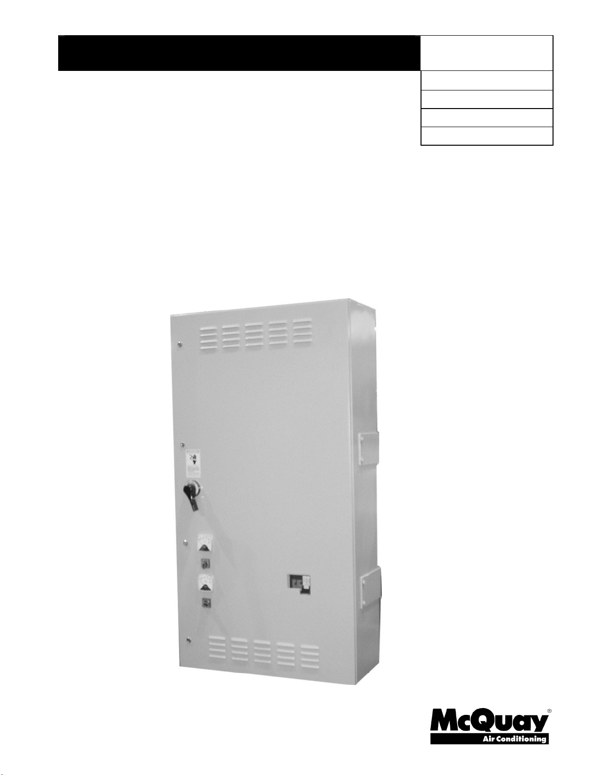
VFD 009LA
Installation, Operation and Maintenance Manual
IOMM VFD-2
Group: Chiller
Part Number: 331375701
Effective: Sept. 2005
Supercedes: IOMM VFD
Variable Frequency Drives
Air-Cooled, LiquiFlo™ and LiquiFlo 2.0™
For Centrifugal Chillers
With MicroTech 200™ or MicroTech II™ Control

2 IOMM VFD-2
Table of Contents
Introduction...........................................3
Environmental Conditions................................5
Harmonic Distortion.........................................5
General Description..............................6
Air-Cooled/LiquiFlo (LF ), Standard Features.6
LiquiFlo 2.0 (LF 2.0), Standard Features.........7
Codes/Standards...............................................7
Quality Assurance ............................................7
A-C/LiquiFlo, Nomenclature ...........................7
LiquiFlo 2.0, Nomenclature.............................7
Definition of Terms...............................9
Installation........................................... 11
Cooling Requirements for VFDs....................13
Separate Cooling Module (LF VFD 090, 120 and
all LF 2.0)....................................................15
Wiring, General..............................................21
Power Wiring.................................................21
Terminal Sizes................................................23
Optional Line Reactor Installation, Air-Cooled/LF
Only.............................................................25
VFD/Chiller Interconnection Wiring Diagram30
VFD Dimensions .................................32
Air-Cooled .....................................................32
LiquiFlo...........Error! Bookmark not defined.
LiquiFlo 2.0.....Error! Bookmark not defined.
MicroTech™ 200 VFD Control..........41
VFD Chiller Control States............................41
Control Sequence, MicroTech 200.................42
WDC/WCC, Dual Compressor VFD Operation43
MicroTech 200 Controller VFD Menu Screens43
MicroTech II™ VFD Control.............50
General Description: ......................................50
Sequence of Operation...................................50
Interface Panel Screens, MT II.......................52
Operation, Small A/C SP600 & LF 2.057
Using the Interface.........................................57
Using the LEDs..............................................59
About Alarms.................................................61
About Faults...................................................64
Troubleshooting.............................................73
Operation, Large A/C, PF700H.........77
Using the Interface.........................................77
Using the LEDs..............................................80
Faults and Alarms...........................................80
Troubleshooting.............................................87
Operation, LF .....................................90
Using the Interface.........................................90
Using the LEDs..............................................93
Troubleshooting.............................................95
Indices: Figures & Tables.................103
©2005 McQuay International
"Information and illustrations cover the McQuay International products at the time of publication and we reserve the right to make changes
in design and construction at anytime without notice".
“McQuay" is a registered trademark of McQuay International LiquiFlo and Reliance are trademarks of Rockwell Automation.
Manufactured in an ISO Certified facility
IOMM VFD-2 3
DANGER
Only qualified electrical personnel familiar with the construction and operation of
this equipment and the hazards involved should install, adjust, operate, or service
this equipment. Read and understand this ma nual and other applicable manuals
in their entirety before proceeding. Failure to observe this precaution could result
in severe bodily injury or loss of life.
DANGER
DC bus capacitors re tain hazardous voltages after power has been disconnected.
After disconnecting input power to the unit, wait five (5) minutes for the DC bus
capacitors to discharge, and then check the voltage with a voltmeter to ensure the
DC capacitors are discharged before touching any internal components. Failure
to observe this precaution could result in severe bodily injury or loss of life.
CAUTION
The user is responsible for conforming to all applicable local, national and
international codes. Failure to observe this precaution could result in damage to,
or destruction of the equipment.
WARNING
The drive contains printed circuit boards that are static-sensitive. Anyone who
touches the drive components should wear an anti-static wristband. Erratic
machine operation and damage to, or destruction of, equipment can result if this
procedure is not followed.
Failure to observe this precaution can result in bodily injury.
Introduction
This manual covers Air-Cooled, LiquiFlo (LF ) and LiquiFlo 2.0 (LF 2.0) VFDs on
centrifugal chillers with MicroTech 200™ or the newer MicroTech II™ controllers. Many
issues are the same for both and are treated in common. Where differences occur,
information will be designated as being for a specific VFD or controller model.
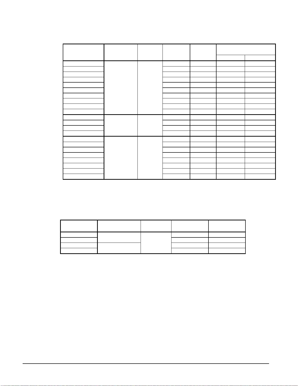
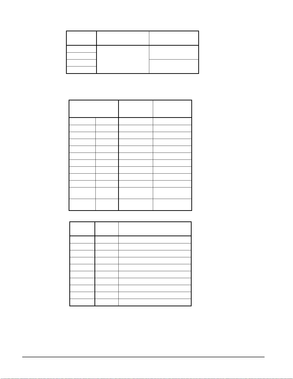
The above three types of VFDs have four family designations as show in Table 1 and Table
2. Each of these VFD families has a separate section in this manual. There is considerable
overlap in programming methods and general operation of the drives, but they are in
separate sections to avoid confusion. The beginning page number for each control section
in the manual is noted in the tables.
4 IOMM VFD-2
Table 1, Model Sizes, Air-Cooled/LiquiFlo
L=Shipped loose, M=Mounted, A=Air-cooled, W=Water-cooled
Optional Line Reactor
(Note 1)
VFD Model
VFD Family
Designation
Page
Location
Max.
Amps
Cooling
Size Amp Rating
VFD 009LA 87 Air RC 100
VFD 009MA 87 Air RC 100
VFD 012LA 114 Air R1 130
VFD 012MA 114 Air R1 130
VFD 015LA 142 Air R2 160
VFD 015MA 142 Air R2 160
VFD 017LA 164 Air R3 200
VFD 017MA 164 Air R3 200
VFD 023LA 225 Air R4 250
VFD 023MA
SP 600 Page 57
225 Air R4 250
VFD 024LA 237 Air RY STD.
VFD 024MA 237 Air RY STD.
VFD 028LA 273 Air RY STD.
VFD 028MA
PF700H Page 77
273 Air RY STD.
VFD 047LW 414 Water RD 500
VFD 047MW 414 Water RD 500
VFD 060LW 500 Water R7 600
VFD 060MW 500 Water R7 600
VFD 072LW 643 Water R8 750
VFD 072MW 643 Water R8 750
VFD 090LW 890 Water RM 900
VFD120LW
LF Page 90
1157 Water R9 1200
NOTES
1. Line reactors are optional on all sizes except Models VFD 024 and 028, where they are included as
standard.
2. Electrical characteristics: 380/460 VAC ±10%, 3 phase, 50/60 Hertz, ±5 Hz.
3. Optional line reactors are 3% impedance.
Table 2, Model Sizes, LiquiFlo 2.0
VFD Model
VFD Family
Designation
Page
Location
Max. Amps Cooling
VF 2037 368 Water
VF 2055
LF 2.0, Frame 3
553 Water
VF 2080 809 Water
VF 2110
LF 2.0, Frame 4
Page 57
1105 Water
WSC and WDC single and dual compressor, and WCC dual compressor chillers can be
equipped with Variable Frequency Drives (VFD). A VFD starts the compressor motor and then
modulates the compressor speed in response to load, evaporator pressure, and condenser
pressure, as sensed by the chiller microprocessor. Despite the small power penalty attributed to
the VFD internal losses, a chiller can achieve outstanding overall efficiency by using a VFD.
VFDs are effective when there is a reduced load, combined with a low compressor lift (lower
condenser water temperatures), dominating the operating hours.
The traditional method of controlling centrifugal compressor capacity is by inlet guide vanes.
Slowing down the compressor, thereby reducing the impeller tip speed, can also reduce
capacity. However, sufficient impeller tip speed must always be maintained to meet the
chiller’s discharge pressure requirements. The speed control method is more efficient than
guide vanes by themselves.
In actual practice, a combination of the two techniques is used. The microprocessor slows the
compressor (to a programmed minimum percent of full load speed) as much as possible,
IOMM VFD-2 5
considering the need for sufficient tip speed, to make the required compressor lift. Then the
guide vanes take over for further capacity reduction. This methodology provides the optimum
efficiency under any operating condition.
Inlet guide vanes control compressor capacity based on a signal from the microprocessor, which
is sensing changes in the leaving chilled water temperature. The guide vanes vary capacity by
changing the angle and flow of the suction gas entering the impeller. The impeller takes a
smaller “bite” of the gas. Reduced gas flow results in less capacity. Compressors start
unloaded (guide vanes closed) in order to reduce the starting effort. A vane-closed switch (VC)
signals the microprocessor that the compressor vanes are closed.
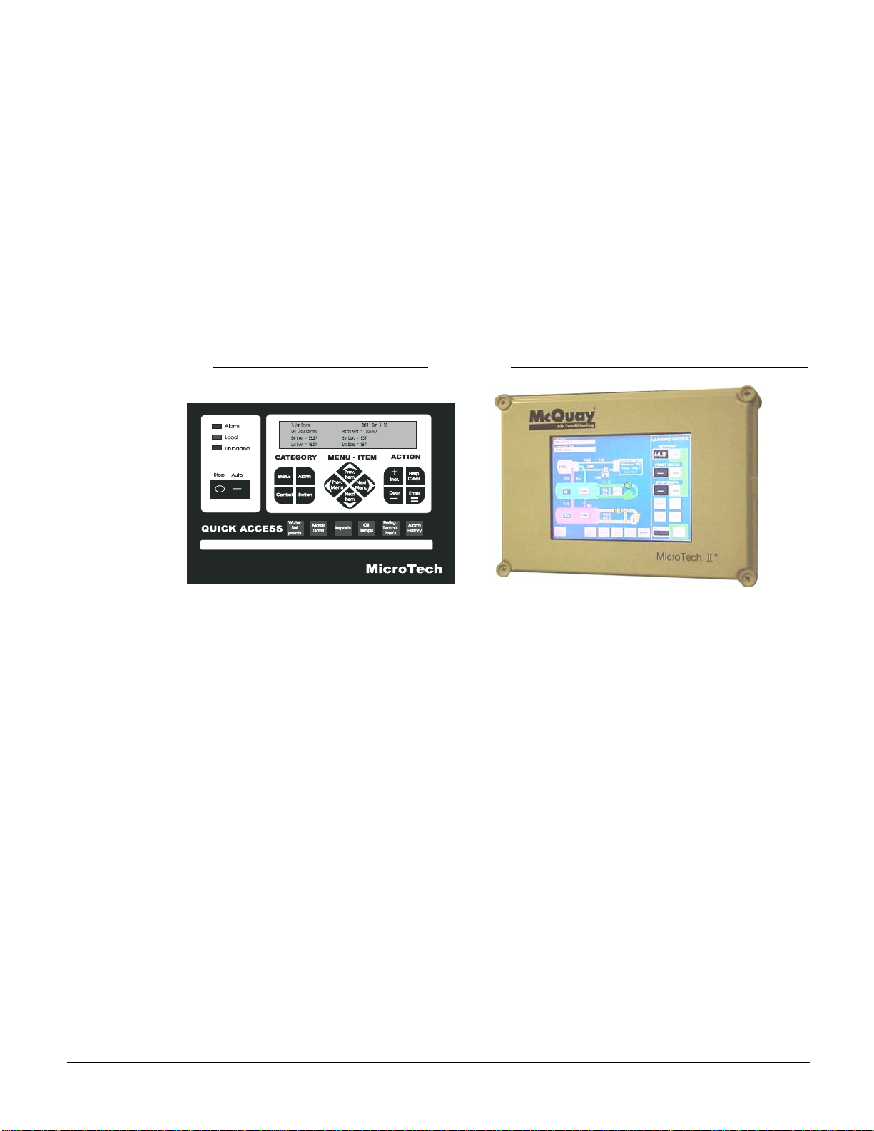
VFDs can be found on centrifugal chillers with the older MicroTech 200 controller (sometimes
referred to as MicroTech I or just plain MicroTech) or the newer MicroTech II™ controller.
The two MicroTech controller versions are easily differentiated as shown below. The
MicroTech II panel shown below is the initial version known as Panel 1. Panel 2, shown on
page 50, replaced it in mid-2005.
Operation and adjustment of the VFD involves settings on both the VFD itself and also to the
chiller controller, either MicroTech 200 controller or MicroTech II controller. This manual
consists of a section relating to VFD operation common to both chiller controllers and also
separate sections for the settings specific to either of the chiller MicroTech controllers.
NOTE: VFDs are programmed differently in the factory for 50 and 60 hertz applications. It is
prudent to verify this by checking the settings sticker in the unit and the actual unit settings
using the Reliance manual shipped with the VFD unit as a reference.
Environmental Conditions
Operating Temperature (inside NEMA 1 enclosure) 32° to 131°F (0°C to 55°C)
Ambient T em perature (outside NEMA 1 enclosure) 32° to 104°F (0°C to 40°C)
Storage Temperature (Ambient) 32° to 131°F (0°C to 55°C)
Humidity 5% to 95% (non-condensing)
AC line distribution system capacity shall not exceed 85,000 amps symmetrical available fault
current.
Harmonic Distortion
Harmonic distortion, the effect that any variable frequency drive has on the electrical system
supplying it power, is a consideration on most applications and is discussed in detail in Catalog
Starter, which can be obtained from the local McQuay sales office or on www.mcquay.com.
MicroTech 200 Control Panel
MicroTech II Operator Interface Panel 1

6 IOMM VFD-2
General Description
The VFD will not generate damaging voltage pulses at the motor terminals when applied
within 500 feet of each other. The VFD drive complies with NEMA MG1 section
30.40.4.2, which specifies these limits at a maximum peak voltage of 600 volts and a
minimum rise time of 0.1 microseconds.
All VFDs require cooling. Models VFD 019 and VFD 028, rated at 273 amps or less, are
air-cooled. All others are water-cooled.
Factory-mounted, water-cooled VFDs have VFD cooling water combined in the factory
with the compressor oil cooling system.
Freestanding water-cooled VFDs require field-installed chilled water supply and return
piping for the VFD. Models VFD 090 and 120 and all LF 2.0 models have an intermediate
cooling module, field installed, between the cooling source and the VFD.
Water-cooled VFD’s have a liquid-cooled heatsink assembly enabling liquid cooling of the
drive though a single inlet and outlet connection point.
There is a temperature-regulating valve located in the drive. It must be set to maintain 95°F
(35°C) leaving coolant temperature. This is necessary to prevent condensation from
forming in the heatsink. Minimum entering coolent temperature is 40°F (4.4°C).
Air-Cooled/LiquiFlo (LF ), Standard Features
• Electronic overload circuit designed to protect an AC motor, operated by the VFD
output, from extended overload operation on an inverse time basis. This electronic
overload is UL and NEC recognized as adequate motor protection. No additional
hardware, such as motor overload relays, or motor thermostats are required.
• An LED display that digitally indicates:
Frequency output Input kW DC bus voltage
Voltage output Elapsed time Motor RPM
Current output Time stamped fault indication
• The VFD is capable of maintaining operation through power dips up to 10 seconds
without a controller trip, depending upon load and operating conditions. In this
extended ride-through, the drive uses the energy generated by the load inertia of the
motor as a power source for electronic circuits.
• An isolated 0-20mA, 4-20mA, or 0-4, 0-8, 0-10 V analog speed input follower.
• An isolated 0-10V or 4-20mA output signal proportional to speed or load.
• Standard I/O expansion interface card with the following features:
• Four isolated 24VDC programmable digital inputs
• One frequency input (0 to 200Hz) for digital control of speed or trim reference
• Four programmable isolated digital outputs (24 VDC rated)
• One Form A output relay rated at 250 VAC or 24VDC
• Two NO/NC programmable output relays rated at 250 VAC or 24 VDC
• The VFD includes the following standard protective circuit features:
• Output phase-to-phase short circuit condition
• Total ground fault under any operating condition
• High input line voltage
• Low input line voltage
• Loss of input or output phase
• External fault (This protective circuit will permit wiring to a remote normally
closed equipment protection contact to shut down the drive.)

IOMM VFD-2 7
LiquiFlo 2.0 (LF 2.0), Standard Features
• NEMA 1 enclosure with hinged door.
• Package includes a circuit breaker with shunt trip with AIC rating of 65,000 amps.
• Full motor voltage is applied regardless of the input voltage.
• Efficiency at rated load and 60 hertz is 97%.
• Drive thermal overload is 110% for 60 seconds in volts per hertz mode and 150% for
five seconds in sensorless vector mode.
• Achieves IEEE519 using actively controlled IGBT front-end maximum of 5% THD.
• 0.99 power factor at full load and provides power factor correction at lighter loads.
• IGBT switching: 2kHz carrier frequency.
• The entire drive package is UL/CUL listed.
• Optional multi language LCD keypad.
• Power line dip ride through capability for up to 10 seconds.
• Adjustable auto restart (number of restarts and time delay between attempts are
selectable.) Display indicates when controller is attempting to restart.
• Control power transformer for chiller unit controls
Codes/Standards
• VFDs are UL 508 listed
• VFDs are designed to comply with the applicable requirements of the latest standards
of ANSI, NEMA, National Electric Code (NEC), NEPU-70, IEEE 519-1992, FCC Part
15 Subpart J, CE 96.
Quality A ssurance
• Every VFD is functionally tested under motor load. During this test the VFD is
monitored for correct phase current, phase voltages, and motor speed. Correct current
limit operation is verified by simulating a motor overload.
• Scrolling through all parameters verifies proper factory presets. The computer port also
verifies that the proper factory settings are loaded into the drive.
• Every VFD’s heatsink is tested to verify proper embedding of the tubing for flow of
coolant liquid. Thermal tests are performed on the VFD to verify that the cooling
occurs within the correct temperature range.
A-C/LiquiFlo, Nomenclature
VFD XXX M A
LiquiFlo 2.0, Nomenclature
Since all LF 2.0 models are field-mounted and water-cooled, there are no characters after
the Model Number, typically VFD 2037.
Mounting
M=Factory-mounted
L= Shipped Loose for
Field Mounting
Cooling Method
A=Air-cooled
W=Water-cooled
Model Number
009 through 120
2037 through 2110 (LF 2)
Variable Frequency Drive
8 IOMM VFD-2
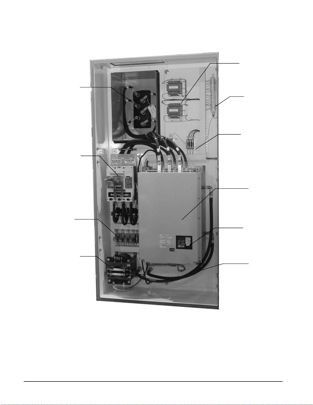
Figure 1, LiquiFlo, Internal Component s, Factory Mounted, Water-Cooled Model
Terminal Board
Optional Meter
Transformers (2)
Fuses
Motor Terminals
Disconnect Switch
Motor Control
Relays (MCR)
Drive Unit
Keyboard/Display
Cooling Water
Lines
Control
Transformer
w/ Fuses
IOMM VFD-2 9
Definition of Terms
Acc2
Acceleration time 2
Active LEWT Setpoint
The current Leaving Evaporator Water Temperature Setpoint
Analog in loss
Analog input loss
Anig Cal Chksum
Analog input calculation check sum, math function
Autotune
Set point adjustments made automatically, not used by McQuay
AutoT MagRot
Autotune rotate, not used by McQuay
AutoT Rs Stat
Autotune static, not used by McQuay
CAN Bus Fit
Controlled area network bus fit
Command Speed
The speed command issued by the MicroTech controller to the VFD
DB
Dynamic breaking (not used on McQuay units)
Dec2
Deceleration 2, not used by McQuay
Decel Inhibit
Deceleration inhibited
Demand Limit
The maximum amp draw as established by the Demand Limit setpoint
Dig in Conflict
Digital input conflict, contradictory instructions
Drive OL
Drive overload
Esc/Prog
Exit a menu, cancel a change to a parameter, or toggle between program and
process (user) display screens.
Flux Amps
Amount of current out of phase with the fundamental voltage component
Full Load
The vane open switch closes and the speed output = 100%. Or
Load pulses exceed the full load setpoint timer (default 300 cumulative
seconds) and the speed output = 100%. Or
% RLA is above or equal to Max Amp Limit or Demand Limit. Or
The evaporator pressure is below the low evap. pressure inhibit setpoint.
FVC
Flux vector control
HIM
Human interface module
IGBT
Insulated Gate Bi-polar Transistors
IntDBResOvrHeat
Dynamic breaking resistor temp. exceeded setpoint(not used on McQuay
units)
Lift Temperature
Saturated condenser refrigerant temperature minus saturated evaporator
temperature.
Lift Temperature Control
Speed
The minimum speed to maintain lift and avoid surge. The controller
continuously calculates the minimum operating speed in all modes, based on
the lift temperature.
Low evap pressure inhibit
setpoint
The low evaporator pressure that inhibits any further compressor loading
Manual Load Setpoint
MicroTech controller manual operation of the guide vanes for testing
Maximum Pulldown Rate
Maximum pulldown rate of chilled water in degrees per minute
MCB
Main control board
MCR
Motor control relay
Minimum Amp Setpoint
MicroTech controller minimum unloading setpoint
Minimum Rate Setpoint
Pulldown rate for MicroTech 200 controller
Minimum Speed
The minimum speed allowed, usually set at 70%
Mod
Module
Net
Network
Network Setpoint
Chilled water setpoint from an external source
NP Hz
OIM
Operator interface module
PCB
Printed circuit board
Continued next page.
10 IOMM VFD-2
Precharge
Precharge capacitors
PWM
Pulse-width-modulated
Rapid Shutdown
If there is a fault, the MicroTech switches the state to VFD OFF. This includes
changing the Unit Control Panel switch to OFF.
RLA
Rated Load Amps, the maximum motor amps
RMI
Remote meter interface, located in the VFD panel
Softloading
Extended ramp-up in capacity, set in the MicroTech controller
Speed
Speed signal to the compressor motor from the variable frequency drive (VFD)
based on analog output (0 – 10 VDC) from the MicroTech controller.
Stage Delta
Multi compressor (or dual compressor unit) on/off cycling temperature delta-T
SVC
Sensorless vector control
Parameters
Throughout this manual, you will see references to parameter names and numbers that
identify them for the drive. This manual uses the same format that will be shown on the
keypad/display to refer to parameters:
P.nnn H.nnn R.nnn
Where: nnn is a number
P designates general parameters
H designates Volts/Hertz parameters
R designates optional RMI parameters
CAUTION
The original parameters values set by the McQuay startup technician must never be
changed by anyone not specifically trained and experienced with these VFDs. Damage
to the chiller or drive could occur.
IOMM VFD-2 11
Installation
Mounting Arrangement s
Depending on size and type, VFDs may be factory-mounted with power and control wiring
factory-installed or free-standing, requiring field mounting remote from the unit and field-
wiring of power and control wiring. Because of dimension restrictions for shipping, some
“factory-mounted” VFDs for some large chillers are shipped separate from the unit.
Mounting supports are on the unit and preassembled cable kits are provided. Mounting and
wiring on site are the customer’s responsibility and can be subcontracted to McQuay
Factory Service if desired.
Factory-Mounted (extra cost option):
The VFD is mounted on the chiller unit with the back
of the VFD against the motor terminal box and wired directly to the motor. This
arrangement is only available on WSC/WDC 063, 079, or 087 units and with LF.
On models WSC/WDC 048/050, the VFD (LF only) is factory-mounted on the front of the
chiller unit and connected to the motor with conduit and cable.
Free-standing (standard):
Floor-mounted, separate from the chiller unit, and field wired to
the compressor motor. This is available on all VFDs and is the only VFD arrangement
available for WDC/WCC 100 and 126 dual compressor units.
Brackets and cable (extra cost option):
VFDs (LF only) for WSC 100 to 126 single
compressor units may be shipped separately from the chiller unit and furnished with
mounting brackets and interconnecting cables for field mounting and connection by others.
This option must be clearly specified when chillers are ordered since brackets are welded
onto the evaporator during its construction.
Table 3, VFD Mounting Arrangements
Air-Cooled/LiquiFlo LiquiFlo 2.0
Chiller
Size
Factory- Mounted Free-Standing Brackets & Cables Free-Standing
WSC/WDC 050 X X X
WSC/WDC 063 X X X
WSC/WDC 079 X X X
WSC/WDC 087 X X X
WSC 100 - 126 X X X
WDC 100 – 126,
WCC 100 - 126
X X
Receiving
Since factory-mounted VFDs are mounted and wired at the factory, this section will only
apply to free-standing units.
The unit should be inspected immediately after receipt for possible damage.
All McQuay centrifugal VFDs are shipped FOB factory and all claims for handling and
shipping damage are the responsibility of the consignee.
Rigging
Extreme care must be used when rigging the equipment to prevent damage. See the
certified dimension drawings included in the job submittal for the center of gravity of the
unit. Consult the local McQuay sales office for assistance if the drawings are not available.
12 IOMM VFD-2
Air-Cooled, The unit can be lifted by fastening the rigging hooks to the two lifting eyes
located on the top of the unit.
LiquiFlo; The unit can be lifted by fastening the rigging hooks to the four lifting eyes
located on the top of the unit.
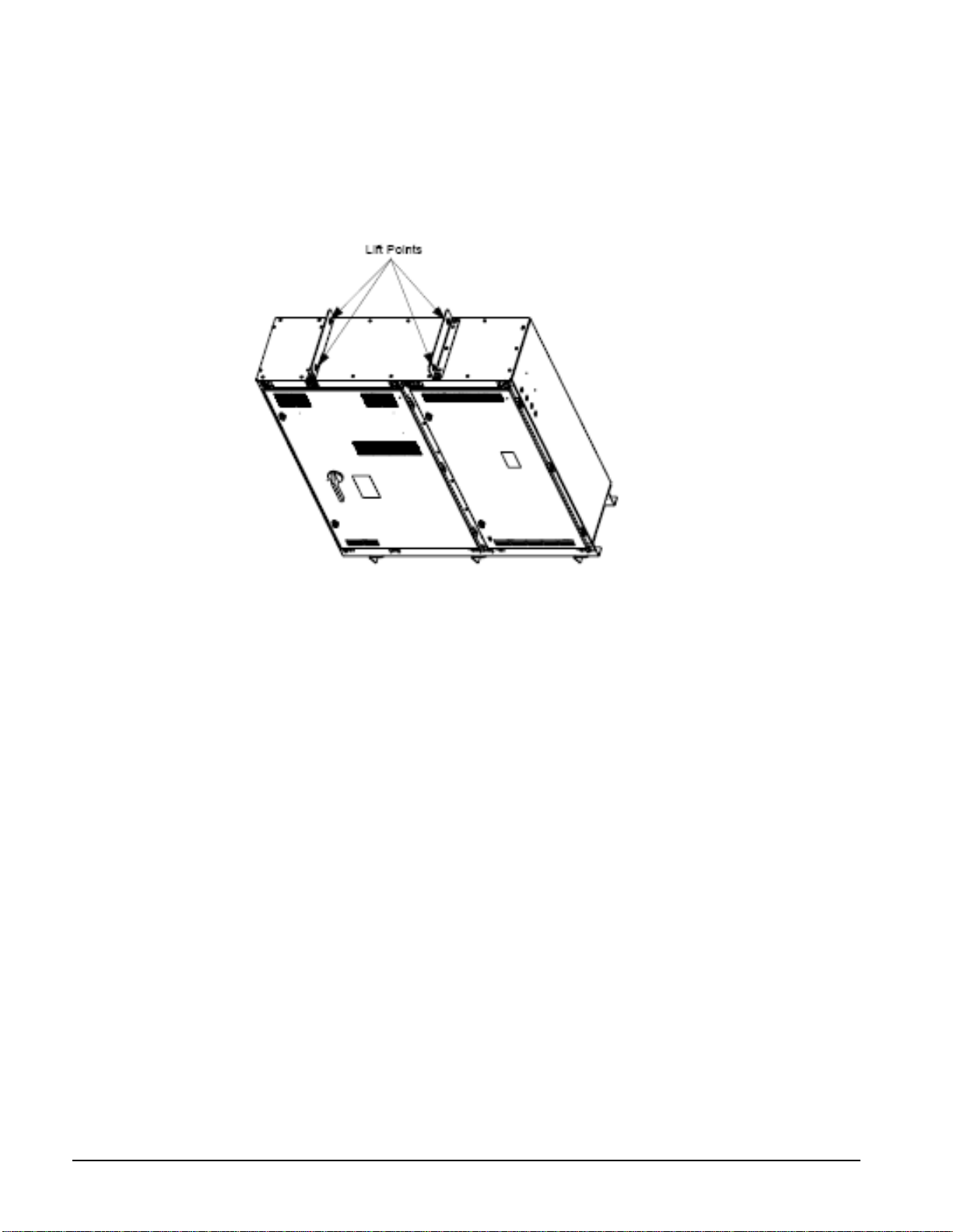
LiquiFlo 2.0:
Figure 2, LF 2.0, Lifting Point s
Use the following procedure to lift and mount the LiquiFlo 2.0 drive:
Step 1. Using an overhead or portable hoist (minimum 2 ton rated capacity), attach a
free-fall chain to the chain secured to the drive. Take up any vertical slack in the chain.
Step 2. Using the hoist, lift the drive from the horizontal shipping pallet.
Step 3. Position the drive.
Step 4. Machine or floor-mount the drive enclosure using 1/2-inch bolts, grade 5 or
better, with compression washers.
Location and Mounting
Location
Consider the following guidelines: •
• Verify that NEMA 1 enclosure drives can be kept clean and dry.
• The area chosen should allow the space required for proper air flow. A minimum of 6-
inch clearance is required wherever vents are located.
• Be sure that the NEMA 1 enclosure is installed away from oil, coolants, or other
airborne contaminants.
• Do not install the drive above 1000 meters (3300 feet) without derating output power.
For every 91.4 meters (300 feet) above 1000 meters (3300 feet), derate the output
current 1%.
• Verify that the drive location meets the environmental conditions specified on page 5.
• Floor-mounted units should be attached to the floor with the C-channel rails provided.

IOMM VFD-2 13
Clearance
The VFDs must be mounted on a level concrete or steel base and must be located to provide
adequate service. Local codes or the National Electric Code (NEC) can require more
clearance in and around electrical components and must be checked.
Mounting
Make sure that the floor or structural support is adequate to support the weight of the unit
shown on the dimension drawing.
Standard NEMA 1 and NEMA 12 VFDs must be installed indoors in an area that is not
exposed to direct water spray. Do not install in areas where the ambient temperature falls
below 32°F (0°C) or exceeds 104°F (40°C) enclosed, or 122°F (50°C) open unless this was
noted at the time of order placement and special precautions were taken to protect against
these abnormal temperatures.
Heatsink temperatures can run as high as 158°F (70°C) during normal operation. Do not
mount the starter in contact with any material that cannot accept this heat. The VFD must
be mounted with the heat sink fins oriented vertically in an area that will not experience
excessive shock or vibration.
Grounding the Drive
Use the following steps to ground the drive:
Step 1. Open the door of the enclosure.
Step 2. Run a suitable equipment grounding conductor unbroken from the drive
enclosure ground lug to earth ground. See figure 2.2. Tighten these grounding
connections to the proper torque.
Step 3. Close the door of the enclosure.
Safety Precautions
Electrical codes require that all equipment (VFD, motor, operator station, etc.) be properly
grounded. An incoming disconnect must be locked open before wiring or servicing the
starter, motor, or other related equipment. The equipment must only be serviced by
qualified personnel fully trained and familiar with the equipment.
The opening of the branch circuit protective device may be an indication that a fault current
has been interrupted. To reduce the risk of electrical shock, current carrying parts and other
components of the starter should be inspected and replaced if damaged.
Equipment is at line voltage when AC power is connected. Pressing the Stop push-button
does not remove AC mains potential. All phases must be disconnected before it is safe to
work on machinery or touch motor terminals and control equipment parts.
Cooling Requirements for VFDs
Air-cooled VFDs: all air-cooled have self-contained cooling systems and require no field
work.
Water-cooleed, factory-mounted VFDs: VFD cooling water piping is factory-connected
to the chiller’s oil cooling system. See Figure 3. Cooling water piping is to the normal
chiller oil-cooling system connections.
Freestanding VFDs: VFD cooling water piping must be field connected on freestanding
units. See Figure 4. Cooling water is connected directly to models 047LA through 072LW.
Models 090LW and 120LW, and all LF 2.0 units, are always freestanding and have a
separate cooling module that must be field piped to the cooling water supply and also
interconnected to the VFD. See page 15 for detailed installation instructions.
14 IOMM VFD-2
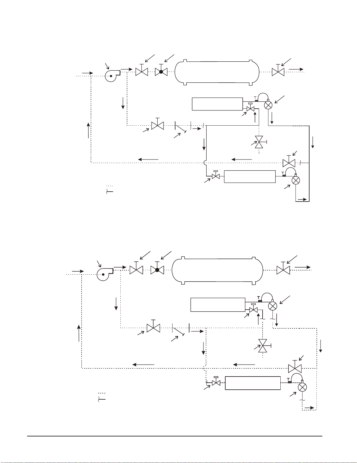
Figure 3, VFD 047 through 072, Cooling Water Piping for Factory-M ount ed VFD
CHILLER
VFD HEAT
EXCHANGER
*
STOP
VALVE
*
STRAINER
MAX. 40 MESH
WATER
REGULATING
VALV E
SOLENOID
VALV E
*
DRAIN VALVE
OR PLUG
*
STOP
VALV E
CHILLED
WATER
PUMP
*
Field Supplied Piping Components
Field Piping
Connection Point
(Factory Mounted)
(Factory Mounted)
*
STOP
VALVE
*
BALANCING
VALV E
*
STOP
VALVE
COMPRESSOR
OIL COOLER CIRCUIT
SOLENOID
VALV E
(Factory Mounted)
WATER
REGULATING
VALV E
(Factory Mounted)
Figure 4, VFD 047 – 120 and all LF 2.0, Cooling Water Piping f or Free- Standing VFD
CHILLER
VFD HEAT
EXCHANGER
*
STOP
VALVE
*
STRAINER
MAX. 40 MESH
WATER
REGULATING
VALV E
SOLENOID
VALV E
*
DRAIN VALVE
OR PLUG
*
STOP
VALVE
CHILLED
WATER
PUMP
*
Field Supplied Piping Components
Field Piping
Connection Point
(Factory Mounted)
(Factory Mounted)
*
STOP
VALV E
*
BALANCING
VALV E
*
STOP
VALV E
COMPRESSOR
OIL COOLER CIRCUIT
SOLENOID
VALV E
(Factory Mounted)
WATER
REGULATING
VALV E
(Factory Mounted)
IOMM VFD-2 15
NOTE: In some cases, the “VFD HEAT EXCHANGER” may be a separate-mounted cooling module that is, in turn, connected
to the VFD.
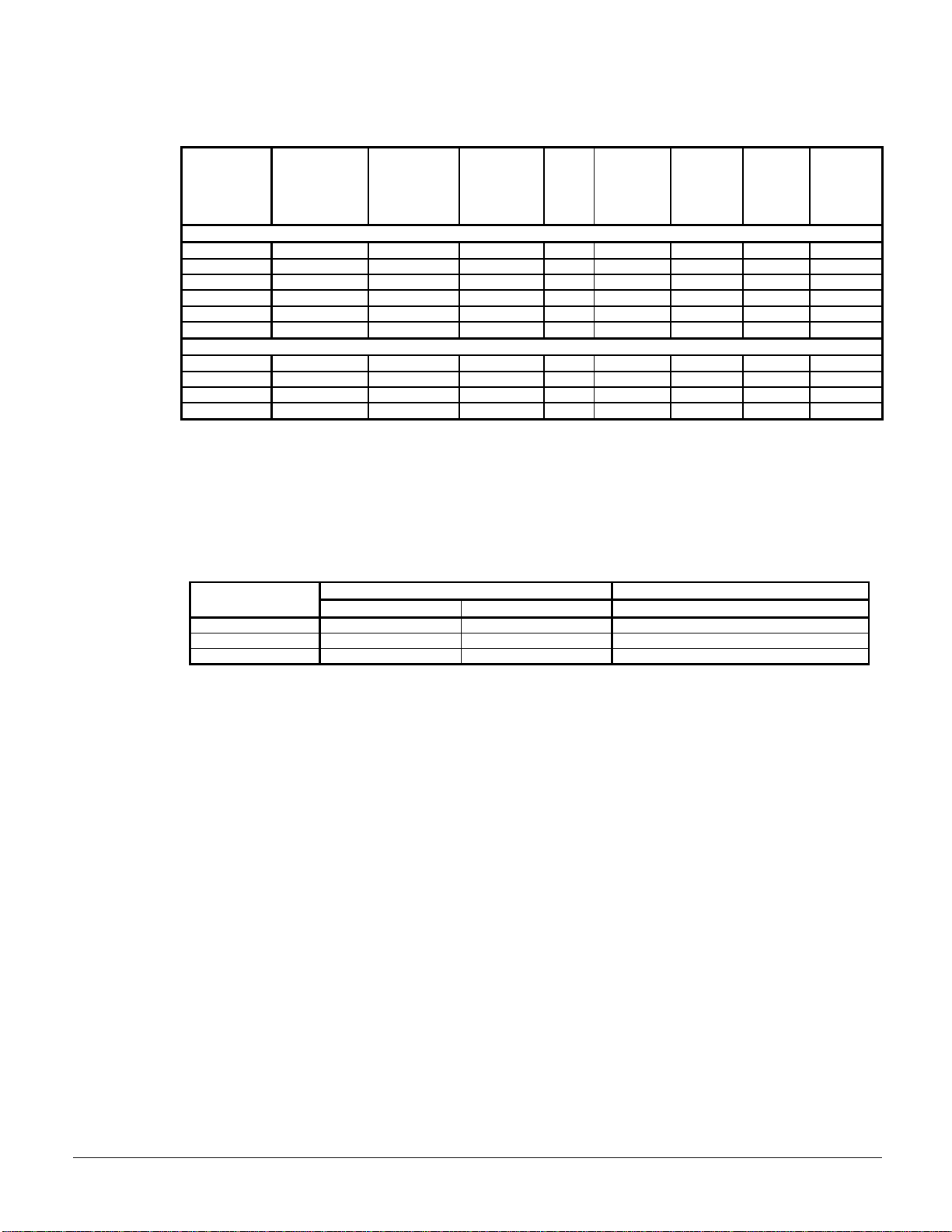
Table 4, Cooling Requirements
McQuay
Drive Model
Number
Combined
Comp. Oil and
VFD Cooling
Copper Tube
Size
VFD Cooling
Only, Copper
Tube Size
Type K or L
Coolant
Method
Flow
(gpm)
Max.
Entering
Coolant
Temp. (° F)
Min.
Entering
Coolant
Temp(° F)
Pressure
Drop
(feet)
Max.
Pressure
(Water
Side) psi
Air-Cooled/LF
VFD 009-028 N/A N/A Air N.A. 104 40 NA N/A
VFD 047 1.0 7/8 in. Water (1) 2.0 90 40 10 (2) 300
VFD 060 1.0 7/8 in. Water (1) 2.0 90 40 30 (2) 300
VFD 072 1.0 7/8 in. Water (1) 2.5 90 40 30 (2) 300
VFD 090 1 1/4 1.0 in. Water (1) (3) 7.0 90 40 30 (2) 300
VFD 120 1 1/4 1.0 in. Water (1) (3) 7.0 90 40 30 (2) 300
LF 2.0
VF 2037 N/A 3/4 NPT Water (1) (3) 7.0 90 40 N.A. 180
VF 2055 N/A 3/4 NPT Water (1) (3) 7.0 90 40 N.A. 180
VF 2080 N/A 3/4 NPT Water (1) (3) 15.0 90 40 N.A. 180
VF 2110 N/A 3/4 NPT Water (1) (3) 15.0 90 40 N.A. 180
Notes:
1. Cooling water must be from the closed, chilled water circuit with corrosion inhibitors for steel and copper, and must be
piped across the chilled water pump.
2. The pressure drop is given for the maximum coolant temperature (maximum flow). The water-regulating valve will
reduce the flow when the coolant temperature is below the maximum in the table. The pressure drop includes the drop
across the solenoid valve, heat exchanger and water regulating valve.
3. Models VFD 090and 120 and all LF 2.0 models have a separate self-contained cooling loop with a recirculating water
pump and heat exchanger, but have the same cooling source water piping as all water-cooled VFDs.
Table 5, Chiller Cooling Water Connection Sizes
Free-Standing VFD, LF and LF 2.0 Factory-Mounted VFD, LF Only
Chiller Unit
To Oil Cooler To VFD Combined
WDC/WCC 100/126 1 1/2 in. FPT ¾ in. MPT 1 1/2 in. FPT
WSC/WDC 050 Not Required Air-Cooled Not Required
All Others 1 in. FPT 3/4 in MPT 1 in. FPT
Separate Cooling Module (LF VFD 090, 120 and all LF 2.0)
The cooling module for the LF models VDF 090 and 120 has a self-contained coolant
temperature control system and no associated programming of the VDF is required. All cooling
modules used with LF 2.0 VFD models are controlled by the VFD and require VFD programming
as shown on page 19. This is done by McQuay at startup.
Closed loop cooling system operation
• A pump circulates a glycol/ water mixture (coolant) through the VFD heat sink, a coolant
reservoir and a small plate heat exchanger. Heat is removed from the VFD heat sink and
rejected to the plate heat exchanger.
• The pump and control valve are controlled by the VFD control system on LF 2.0 VFD models
and self-contained on LF models.
• The plate heat exchanger is cooled by water from the chilled water system
Installation steps:
• Place cooling loop module in desired location.
• Attach coolant and chilled water piping. Seven to nine gpm of coolant will be circulated. A
40 mesh strainer is required at the drive inlet. Include service isolation valves in the coolant
and chilled water inlet and outlet piping.

16 IOMM VFD-2
• Wire according to the supplied wiring diagrams.
IOMM VFD-2 17
The following is required from the customer's chilled water supply for the McQuay VFD cooling
loop to perform properly.
Water Quality:
Water must be compatible with components supplied in the cooling loop; brass, copper, stainless
steel and neoprene rubber seals. Supply water circulates through a copper brazed stainless steel,
plate type heat exchanger by way of a stainless steel and brass ball valve and associated stainless
steel, brass and copper piping.
Water Source:
Clean and non-corrosive chilled water must be used as the coolant.
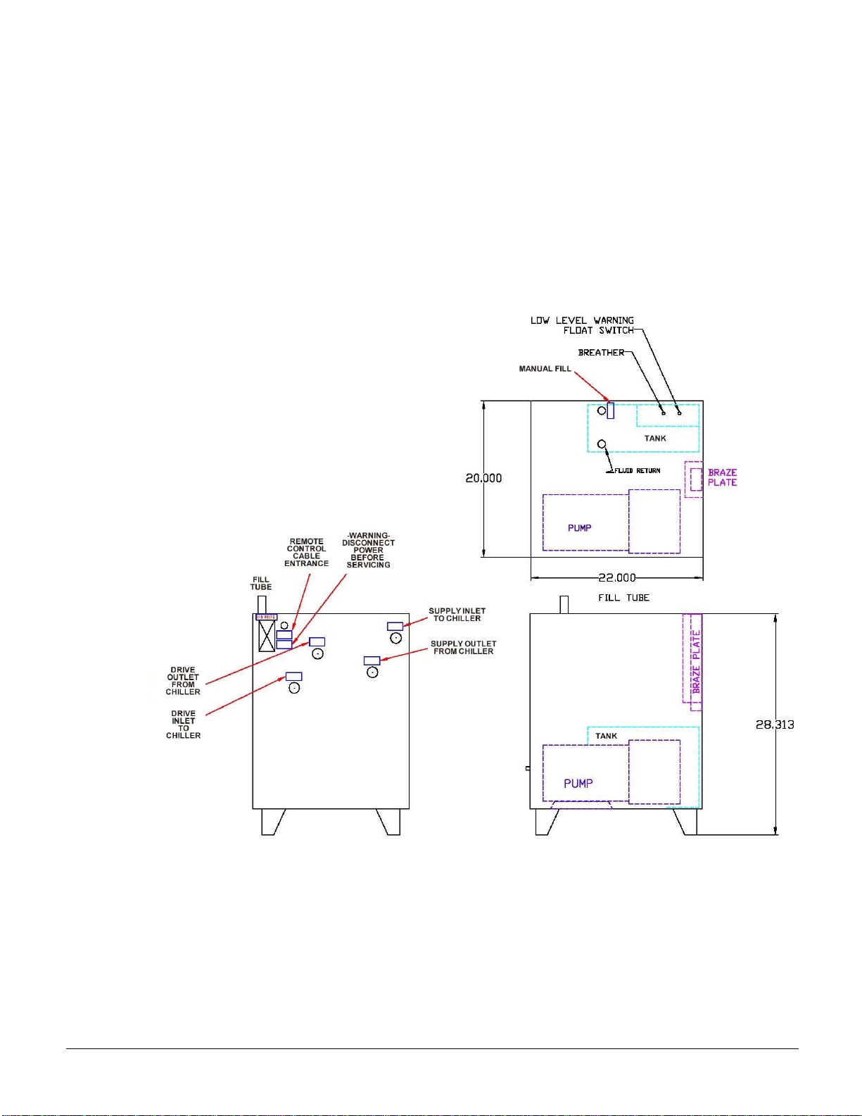
Figure 5, Cooling Module Dimensions
Weights
Shipping weight: 300 lbs (136 kg)
Dry weight: 250 lbs (114 kg)
Operating weight: 270 lbs. (123 kg)
18 IOMM VFD-2
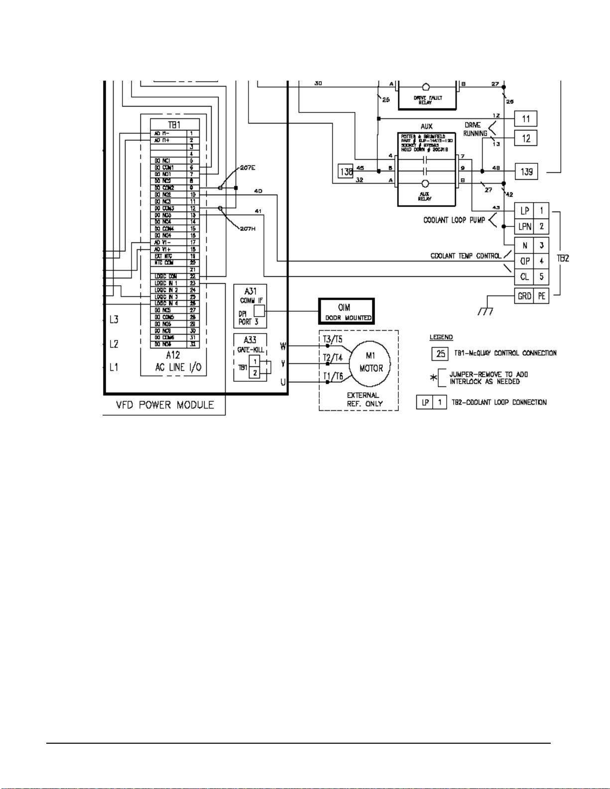
Figure 6, LF 2.0 Remote Cooling Module Int erconnect i ng Wiring
TB2 is the terminal board located in the remote module.
TB1 is a terminal board located in the VFD.
Field Wiring:
• TB1-10 (DO NO2) to TB2-4 (OP, Open)
• TB1-13 (DO NO3) to TB2-5 (CL, Close)
• Wire 42 (Aux Relay) to TB2-3 (Neutral)
• Wire 42 (Aux Relay) to TB2-2 (LPN, Loop Pump Neutral)
• Aux Relay Terminal 7 to TB2-1 (LP, Loop Pump)
• GRD (PE) to Ground

IOMM VFD-2 19
Maximum Static Pressure:
300 psi nominal limited by ball valve and piping pressure ratings.
Requirements for proper operation of the drive/ cooling module
cooling loop.
Cooling Loop Liquid:
25% inhibited (corrosion protected) propylene glycol (DOWFROST or equivalent)
concentration by volume with distilled water. Non-inhibited or silicate containing glycols
may cause equipment damage.
Coolant Volume:
Approx. 1 gallon is required with side-by-side connection of cooling module to the drive
cabinet. More coolant volume will be required if coolant loop is located up to 20 feet away
from drive.
Coolant Maintenance:
The coolant liquid should be checked and refreshed as needed on a yearly basis. The pH
should be maintained between 8.0 and 10.0. A 50% solution of sodium hydroxide or
potassium hydroxide can be used to raise pH if falls below 8.0. Any time the coolant falls
below a pH of 7.0 the loop should be flushed and coolant replaced. Any time the coolant
appears other than water white it should be replaced.
Remote Mounted Cooling Loop:
The maximum distance the cooling loop can be installed away from the drive cabinet
connections is 20 feet. Careful planning of remote mounting is required to minimize
coolant flow restrictions introduced by piping connections.
Cooling Module Parameters Set in LF 2.0 VFD models
LF 2.0 drives control the operation of the cooling module. The parameters are set by
McQuay at chiller commissioning.
How to Monitor Cooling Loop Operation
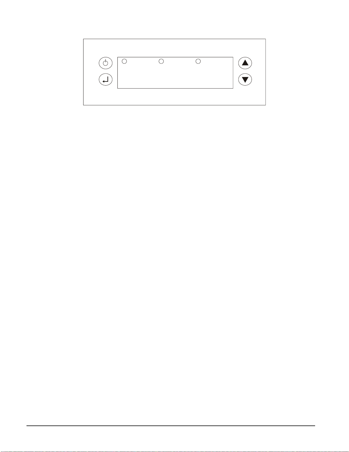
FX-05 Screen Navigation (see Figure 7)
After power-up the process temperature will be displayed.
Alarms
When an alarm is present the alarm LED will blink fast and the error code will flash. The
following is a list of the error code.
• E0: OK
• E1: Low Level Fault
• E2: Fluid Over-Temperature Fault
• E3: Fluid Under-Temperature Fault
• E4: Fluid Low Flow Fault
To acknowledge the alarms hold the φ key for 3 seconds. The alarm error code will be
displayed and the reset led will light while the button is depressed. After the φ key is
released the process temperature will be displayed.
To view the alarm summary hold both the ↵ ↓ keys for 3 seconds. To exit the alarm
summary screen press the φ key or the screen will automatically time out after 10 seconds.
20 IOMM VFD-2
Figure 7, FX05 Display Panel
ALARM RESET PUMP ON
Fx05
Operation
The FX controller controls to a fixed loop water setpoint.
IOMM VFD-2 21
Wiring, General
Unit-Mounted: Unit mounted VFDs have factory-wired control wiring plus power wiring
from the VFD to the compressor motor terminals. The VFDs only require a power supply.
Cable entrance is shown on the dimension drawings beginning on page 32 for LF and page
Error! Bookmark not defined. for LF 2.0 models. An exception is on models LF models
090 and 120 and all LF 2.0 models that require some interconnection control wiring from
the VFD to the remote cooling module as described in the section beginning on page 15.
Freestanding: Freestanding units require both field control and power wiring from the
VFD to the chiller and. some interconnection control wiring on models 090 and 120.
Wiring Diagram: The control and power wiring diagram is located on page 25.
Power Wiring
Wiring, fuse and wire size must be in accordance with local codes and the National Electric
Code (NEC).
CAUTION
Voltage unbalance not to exceed 2% with a resultant current unbalance of 6 to
10 times the voltage unbalance per NEMA MG-1, 1998 Standard. This is an
important requirement to avoid excessive motor or drive heating.
WARNING
Qualified and licensed electricians must perform wiring. Shock hazard exists.
Power wiring to compressors must be in proper phase sequence. Motor rotation is set up
for clockwise rotation facing the lead end with phase sequence of 1-2-3. Care must be
taken that the proper phase sequence is carried through the VFD to the compressor. With
the phase sequence of 1-2-3 and L1 connected to T1 and T6, L2 connected to T2 and T4,
and L3 connected to T3 and T5, rotation is proper. See diagram in terminal box cover.
The McQuay start-up technician will check the phase sequence.
CAUTION
Connections to terminals must be made with copper lugs and copper wire.
Care must be taken when attaching leads to compressor terminals.
Note: Do not make final connections to motor terminals until wiring has been
checked and approved by a McQuay technician.
Under no circumstances should a compressor be brought up to speed unless proper
sequence and rotation have been established. Serious damage can result if the compressor
starts in the wrong direction. Such damage is not covered by product warranty.
Compressor Motor Terminal Insulation
It is the installing contractor's responsibility to insulate the compressor motor terminals (as
described below) when the unit is installed in a high humidity location that could cause
condensate to form on the motor terminals. The terminals are cooled to 45°F to 50°F as a
result of the motor cooling. The required material can be ordered and shipped in as a kit
(775123601).

22 IOMM VFD-2
This is to be done after the McQuay start-up technician has checked for proper phase
sequence and motor rotation.
Following this verification by the McQuay technician, the contractor should apply the
following items.
Materials required:
1. Loctite® brand safety solvent (12 oz. package available as McQuay part number
350A263H72)
2. 3M™ Co. Scotchfil brand electrical insulation putty (available in a 60-inch roll as
McQuay part number 350A263H81)
3. 3M Co. Scotchkote™ brand electrical coating (available in a 15 oz. can with brush as
McQuay Part Number 350A263H16)
4. Vinyl plastic electrical tape
The above items are available at most electrical supply outlets.
Application procedure:
1. Disconnect and lock out the power source to the compressor motor.
2. Using the safety solvent, clean the motor terminals, motor barrel adjacent to the
terminals, lead lugs, and electrical cables within the terminal 4OX to remove all dirt,
grime, moisture and oil.
3. Wrap the terminal with Scotchfil putty, filling in all irregularities. The final result
should be smooth and cylindrical.
4. Doing one terminal at a time, brush the Scotchkote coating on the motor barrel to a
distance of up to '/2" around the terminal and on the wrapped terminal, the rubber
insulation next to the terminal, and the lug and cable for approximately 10". Wrap
additional Scotchfil insulation over the Scotchkote coating.
5. Tape the entire wrapped length with electrical tape to form a protective jacket.
6. Finally, brush on one more coat of Scotchkote coating to provide an extra moisture
barrier.
IOMM VFD-2 23
General Wiring Practice
1. Never connect input AC power to the motor output terminals T1/U, T2/V or
T3/W.
2. Power wiring to the motor must have the maximum possible separation from all
other wiring. Do not run control wiring in the same conduit; this separation
reduces the possibility of coupling electrical noise between circuits. Minimum
spacing between metallic conduits containing different wiring groups should be
three inches (76 mm).
3. Minimum spacing between different wiring groups should be six inches (152
mm).
4. Wire runs outside of an enclosure should be run in metallic conduit or have
shielding/armor with equivalent attenuation.
5. Different wire groups should cross at 90 degrees whenever power and control
wiring cross.
6. Different wire groups should be run in separate conduits.
7. Adhere to local electrical codes.
8. The National Electrical Code and Canadian Electrical Code requires that an
approved circuit disconnecting device be installed in series with the incoming
AC supply in a location readily accessible to personnel installing or servicing
this equipment. If a disconnect switch is not supplied with the starter, one must
be installed.
9. Supply lines and motor lines may enter the enclosure from the top, bottom or
sides. Wire connections can be determined to best suit specific installations.
Wire runs should be properly braced to handle both starting and fault currents.
Size power cable per local electrical codes. Long lengths of cable to the motor
of over 150 feet must be de-rated.
Terminal Sizes
Compressor Motor Terminals
Power wiring connections at the motor are “spark plug” type terminals with threaded
copper bar, sized per the following table.
Table 6, Chiller Compressor Motor Terminal Sizes
Type/Size Comp. Size Terminal Size
Low Voltage to 275 A, to 575 V CE 050 0.375-16 UNC2A, 0.94 in. long
Low Voltage to 750 A, to 575V CE 063-126 0.635-11 UNC-2A, 1.88 in. long
VFD Terminals
For field wiring freestanding VFDs, the outgoing terminals and incoming power
block terminals are determined by the VFD size listed in Table 8. For factory-
mounted VFDs, the outgoing terminals are factory-connected to the compressor
motor.
When wiring to a VFD with a disconnect switch or circuit breaker, the incoming lug
size is determined by the device size as shown in Table 9.
24 IOMM VFD-2
Table 7, LiquiFlo 2.0, Terminal Size Range
VFD Size
Incoming Terminals Outgoing
Terminals
VF2037
VF2055
(3) 1.5 inch wide tab
w/ 0.472 inch hole
VF2080
VF2110
Incoming connecti on is
to the standard circuit
breaker. See
Table 9.
(3) 2.25 inch wide tab
w/ 0.56 inch hole
Table 8, Air-Cooled/LiquiFlo, Outgoing, Incoming Power Block,
Terminal Size Range
VFD Size
Incoming
Power Block
Terminals
Outgoing
Terminals
VFD 009 SP600 #14 – 1/00 #14 – 1/00
VFD 012 SP600 #4 – 3/0 #4 – 3/0
VFD 015 SP600 #14 - 250 #14 - 250
VFD 017 SP600 #14 - 250 #14 - 250
VFD 023 SP600 #14 - 250 #14 - 250
VFD 024 PF700H 4/0 - 350 4/0 - 350
VFD 028 PF700H 4/0 - 350 4/0 - 350
VFD 047 LF (2) #4 - 500 (2) #6 - 300
VFD 060 LF (2) #4 - 500 (2) #4 - 350
VFD 072 LF (2) #4 - 500 (2) #4 - 350
VFD 090 LF (2) #4 - 500
2 in. x 1/4 in. bus
(1) 9/16 in. hole
VFD 120 LF (2) #4 - 500
2 in. x 1/4 in. bus
(1) 9/16 in. hole
Table 9, Incoming Terminal Size Range, Disconnects & Circuit Breakers
Max
RLA
Size
Incoming Terminal, Disconnect
Switch or Circuit Breaker
74 100 (1) #6- 300
93 125 (1) #6- 300
148 200 (1) #6- 300
163 220 (1) 4/0 - 500
185 250 (2) 3/0 - 500
296 400 (2) 3/0 - 500
444 600 (3) 1/0 - 500
593 800 (4) 250 – 500
889 1200 (5) 300 – 600
1185 1600 (5) 300 - 600
NOTE: (X) is the number of terminals per phase.

IOMM VFD-2 25
Optional Line Reactor Installation, Air-Cooled/LF Only
Mounting Options
Optional line reactors can be mounted in the VFD enclosure on free-standing units and must
be field-mounted and wired when the VFD is factory-mounted. When the reactor is installed
in the VFD enclosure, a much larger enclosure is required and it is too large to mount on the
chiller.
VFD Line Harmonics
VFDs have many benefits, but care must be taken when applying VFDs due to the effect of
line harmonics on the building electric system. VFDs cause distortion of the AC line because
they are nonlinear loads, that is, they don't draw sinusoidal current from the line. They draw
their current from only the peaks of the AC line, thereby flattening the top of the voltage
waveform. Some other nonlinear loads are electronic ballasts and uninterruptible power
supplies.
Reflected harmonic levels are dependent on the source impedance and the KVA of the of the
power system to which the drive is connected. Generally, if the connected power source has
a capacity greater than twice the drive’s rated amps (see Table 1 or Table 2 for rated amps),
the installation will conform to IEEE Standard 519 with no additional attenuation.
Presumably, the application on which this drive is applied has been checked for harmonic
levels. If not, contact the local McQuay office.
The IEEE 519-1991 Standard
The Institute of Electrical and Electronics Engineers (IEEE) has developed a standard that
defines acceptable limits of system current and voltage distortion. A simple form is available
from McQuay that allows McQuay to determine compliance with IEEE 519-1991. Line
harmonics and their associated distortion may be critical to AC drive users for three reasons:
1. Current harmonics can cause additional heating to transformers, conductors, and
switchgear.
2. Voltage harmonics upset the smooth voltage sinusoidal waveform.
3. High-frequency components of voltage distortion can interfere with signals transmitted
on the AC line for some control systems.
The harmonics of concern are the 5
th
, 7
th
, 11
th
, and 13
th
. Even harmonics, harmonics divisible
by three, and high magnitude harmonics are usually not a problem.
Current Harmonics
An increase in reactive impedance in front of the VFD helps reduce the harmonic currents.
Reactive impedance can be added in the following ways:
1. Mounting the drive far from the source transformer.
2. Adding line reactors.
3. Using an isolation transformer.
Voltage Harmonics
Voltage distortion is caused by the flow of harmonic currents through a source impedance. A
reduction in source impedance to the point of common coupling (PCC) will result in a
reduction in voltage harmonics. This may be done in the following ways:
1. Keep the point of common coupling (PCC) as far from the drives (close to the power
source) as possible.
2. Increase the size (decrease the impedance) of the source transformer.
26 IOMM VFD-2
3. Increase the capacity of the busway or cables from the source to the PCC.
4. Make sure that added reactance is "downstream" (closer to the VFD than the source) from
the PCC.
DANGER
High voltage is used in the operation of line/load reactors. Use Extreme caution to
avoid contact with high voltage when operating, installing or repairing equipment
containing line/load reactors.
INJURY OR DEATH MAY RESULT IF SAFETY PRECAUTIONS ARE NOT
OBSERVED
DANGER
Even if the upstream disconnect/protection device is open, a drive or inverter
down stream of the line/load reactor may feed back high voltage to the reactor.
The inverter or drive safety instructions must be followed.
INJURY OR DEATH MAY RESULT IF THE SAFETY PRECAUTIONS ARE NOT
OBSERVED
CAUTION
An upstream disconnect/protection device must be used as required by the
National Electrical Code
CAUTION
The frame of line/load reactors must be grounded at least at one of the reactor’s
mounting holes.
This section is intended for use by personnel experienced in the operation and maintenance
of electronic drives, inverters and similar types of power electronic equipment. Because of
the high voltages required by the equipment connected to line reactors and the potential
dangers presented by rotating machinery, it is essential that all personnel involved in the
operation and maintenance of line/load reactors know and practice the necessary safety
precautions for this type of equipment. Personnel should read and understand the
instructions contained in this section before installing, operating or servicing line/load
reactors and the drive to which the reactor is connected
AGENCY A PPROVALS:
UL-508, File E180243 Component Recognized (1 amp – 2400 amps)
UL-508, File E180243 UL Listed Nema 1 units (1 amp – 2400 amps)
CSA C22.2, File LR29753-13 CSA Certified (1 amp – 1200 amps)
Class H, 200 C, File E66214, Type 180-36, UL Recognized Insulation System
CE
IOMM VFD-2 27
Ambient Temperature
Maximum ambient temperature is 45°C (113°F).
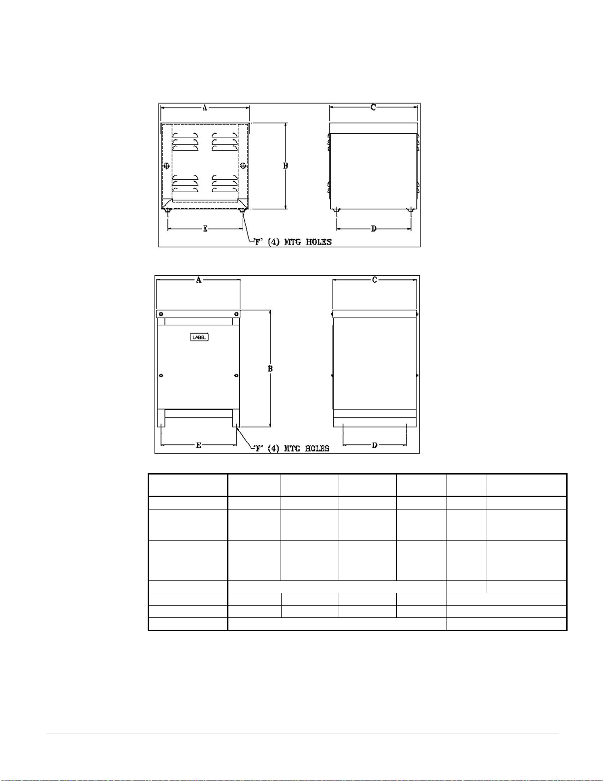
Figure 8, Line Reactor Dimensions, Models VFD 009 - 017
Figure 9, Line Reactor Dimensions, Models VFD 047 - 072
Table 10, Line Reactor Data
VFD Model
Width “A”
in. (mm)
Depth “C”
in. (mm)
Height “B”
in. (mm)
Weight
lbs (kg)
Wire
Range
Torque
In. lb.
009MA 13.2 (335) 13.2 (335) 13.2 (335) 86 (39) 6-0 6-4=45, 2-0=500
012MA–017MA 13.2 (335) 13.2 (335) 13.2 (335) 98 (44) 2-0000
2-1=150, 1/0-
2/0=180, 3/0-
4/0=250
023MA 17.0 (432) 17.0 (432) 24.0 (610) 151 (69) 00-500
00=180, 000-
0000=250
250-350=325,
500=375
024-028 See Note 3
047MW-060MW 17.0 (432) 17.0 (432) 24.0 (610) 225 (102) See Note 2
072MW 24 (610) 24 (610) 30 (762) 393 (178) See Note 2
090LW-120LW See Note 3 See Note 4
NOTES:
1. Models 012MA through 023MA have box lugs, one wire per lug.
2. Models 047MW through 072MW have copper tabs with (1) 0.656 hole.
3. Models 024LA/MA through 028LA/MA have reactor as standard and it is mounted in VFD.
Wiring required to incoming reactor terminals.
4. Models 090LW through 120LW have (2) 0.656 holes, and are always shipped loose with reactors
factory-mounted in VFD. Wiring required to incoming terminals.
28 IOMM VFD-2
Mounting
NEMA 1 enclosures designed for floor mounting must be mounted with the enclosure base
horizontal for proper ventilation. Wall mounting a floor mounted enclosure with the base
against the wall will cause the reactor to over heat resulting in equipment damage.
Allow a minimum side, front, and back clearances of 12 inches (305 mm) and vertical
clearances of 18 inches (457 mm) for proper heat dissipation and access. Do not locate the
enclosure next to resistors or any other component with operating surface temperatures above
260°F (125°C).
Allow a minimum side, front, and back clearances of 12 inches (305 mm) and vertical
clearances of 18 inches (457 mm) for proper heat dissipation and access. Do not locate the
enclosure next to resistors or any other component with operating surface temperatures above
260°F (125°C).
Select a well ventilated, dust-free area away from direct sunlight, rain or moisture, where the
ambient temperature does not exceed 45°C (113°F).
Do not install in or near a corrosive environment.
Avoid locations where the reactor will be subjected to excessive vibrations.
Where desirable, enclosures may be mounted on vibration isolating pads to reduce audible
noise. Standard vibration control pads made from neoprene or natural rubber and selected for
the weight of the enclosed reactor are effective.
Reactor Power Wiring
WARNING
Input and output power wiring to the reactor must be performed
by authorized personnel in accordance with the NEC
and all local electrical codes and regulations.
Verify that the power source to which the reactor is to be connected is in agreement with the
nameplate data on the reactor. A fused disconnect switch or circuit breaker should be
installed between the reactor and its source of power in accordance with the requirements of
the NEC and all local electrical codes and regulations. Refer to the drive, inverter, or other
electrical equipment user manual for selection of the correct fuse rating and class.
The reactor is suitable for use on a circuit capable of delivering not more than 65,000 rms
symmetrical amperes at 480 volts when protected by Bussman type JJS, KTK, KTK-R, PP or
T class fuses.
Reactors are designed for use with copper conductors with a minimum temperature rating of
75°C. Table 10 lists the wire range for the power input and output connections by VFD
model.
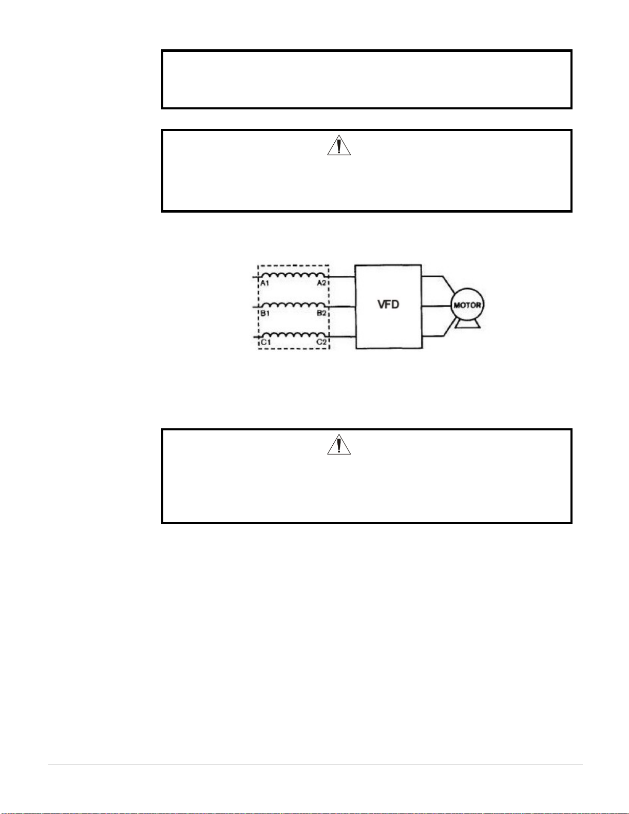
Refer to
Figure 10 for a typical electrical diagram of a reactor in its proper location, upstream of a
VFD.
Where desirable, a flexible conduit connection to the reactor enclosure should be made to
reduce audible noise.
IOMM VFD-2 29
Failure to connect reactors supplied as a component part of a drive system or
other power electronic system according to the system interconnection diagram
supplied by the System Engineer will result in equipment damage, injury, or
death.
WARNING
If a line reactor or a line reactor and a load reactor are used with a drive equipped
with a bypass circuit, the reactors must be removed from the motor circuit in the
bypass mode. Damage to the motor and other equipment will result if this
warning is not observed.
Figure 10, Line Reactor Wiring
Grounding
A stud is provided in the reactor enclosure for grounding the enclosure. The enclosure must
be grounded.
WARNING
The frame of line/load reactors must be grounded at the designated grounding
terminal or one of the reactor mounting holes if no designated grounding terminal
is provided. The enclosure of reactors supplied in enclosures must be grounded.
INJURY OR DEATH MAY RESULT IF SAFETY PRECAUTIONS ARE NOT
OBSERVED.
30 IOMM VFD-2
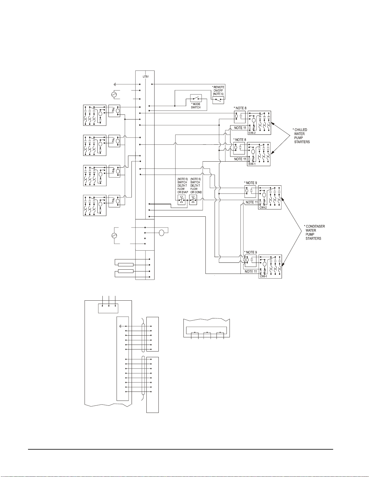
VFD/Chiller Interconnection Wiring Diagram
Figure 11, Control and Power Wiring Diagram
80
CP2
CP1
H
O
A
C4
H
A
O
C3
H
A
O
79
78
77
74
73
54
CF
86
EF
86
C
25
1
2
11
11
12
22
1
2
11(6 )
11
12
22
NOTE 2
NOTE 2
(115V) (24V)
25
55
70
H
A
O
H
A
O
H
O
A
C
H
O
A
C
H
O
A
C
C2
C1
T3-S
PE
L1
L2
CP2
CP1
24
23(5A)
24(5)
23
3
4
3
4
76
75
PE
85
86
81
84
A
82(NO)
83(NC)
POWER
EP2
EP1
L1 L2 L3
GND
UV W
T4 T3 T5T1 T6 T2
GND
LESS
THAN
30V
OR
24VAC
53
71
71
52
1-10 VDC
1-10 VDC
MI
C
R
O
TE
C
H
CO
NTR
O
L
BOX TERMINALS
* COOLING
TOWER
FOURTH
STAGE
STARTER
* COOLING
TOWER
THIRD
STAGE
STARTER
* COOLING
TOWER
SECONDH
STAGE
STARTER
* COOLING
TOWER
FIRST
STAGE
STARTER
COOLING TOWER
BYPASS VALVE
COOLING TOWER VFD
ALARM RELAY
(NOTE 4)
MICROTECH
COMPRESSOR CONTROL
BOX TERMINALS
CTB1
-LOAD-
COMPRESSOR
MOTOR
STARTER
(NOTE 1)
115 VAC
STARTER LOAD SIDE TERMINBALS
VFD
COMPRESSOR TERMINALS
- COMPRESSOR CONTROL
SCHEMATIC 330342201
- LEGEND: 330343001
* FIELD SUPPLIED ITEM
* NOTE 7
* NOTE 10
* NOTE 10
* NOTE 10
* NOTE 10
330387901-0A
COMMON
NEUTRAL
POWER
See notes on following page.
 Loading...