

Page 1
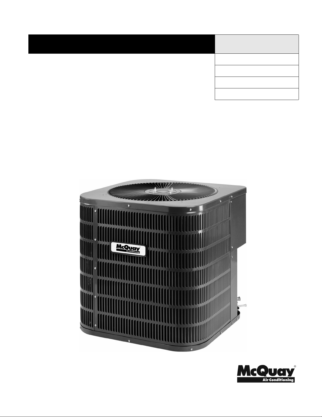
Installation and Maintenance Manual IM-801
AHP Split System Heat Pumps
1-1/2 to 5 tons
Group: Unitary
Part Number: IM-801
Date: August 2005
Supersedes: January 2005
© 2004 McQuay International
IM-801 Page 1
Page 2
Table of Contents
MODEL NOMENCLATURE. . . . . . . . . . . . . . . . . . . . . . . . . . 3
INTRODUCTION . . . . . . . . . . . . . . . . . . . . . . . . . . . . . . . . . 4
GENERAL WARNINGS . . . . . . . . . . . . . . . . . . . . . . . . . . . . 4
SCROLL COMPRESSORS . . . . . . . . . . . . . . . . . . . . . . . . . 4
INSTALLATION . . . . . . . . . . . . . . . . . . . . . . . . . . . . . . . . . . 5
ELECTRICAL . . . . . . . . . . . . . . . . . . . . . . . . . . . . . . . . . . . . 6
COMPONENTS . . . . . . . . . . . . . . . . . . . . . . . . . . . . . . . . . . 6
PIPING . . . . . . . . . . . . . . . . . . . . . . . . . . . . . . . . . . . . . . . . . 6
EVAPORATOR COIL . . . . . . . . . . . . . . . . . . . . . . . . . . . . . . 7
INDOOR CFM AND HEATING CAPACITY
DETERMINATION . . . . . . . . . . . . . . . . . . . . . . . . . . . . . . . . .7
REFRIGERANT CHARGE DETERMINATION AND
ADJUSTMENT - HEAT PUMP - COOLING CYCLE . . . . . .10
HEAT PUMP - HEATING CYCLE . . . . . . . . . . . . . . . . . . . .11
STARTUP PROCEDURE AND CHECK LIST . . . . . . . . . . .11
OPERATION - DEFROST CONTROL . . . . . . . . . . . . . . . .12
MAINTENANCE . . . . . . . . . . . . . . . . . . . . . . . . . . . . . . . . .13
WIRING DIAGRAM . . . . . . . . . . . . . . . . . . . . . . . . . . . . . . .14
THERMOSTAT DIAGRAM . . . . . . . . . . . . . . . . . . . . . . . . .15
"McQuay" is a registered trademark of McQuay International.
"Illustrations and information cover the McQuay International products at the time of publication and we reserve the right to make changes in
Page 2 IM-801
design and construction at any time without notice."
© 2004 McQuay International
Page 3
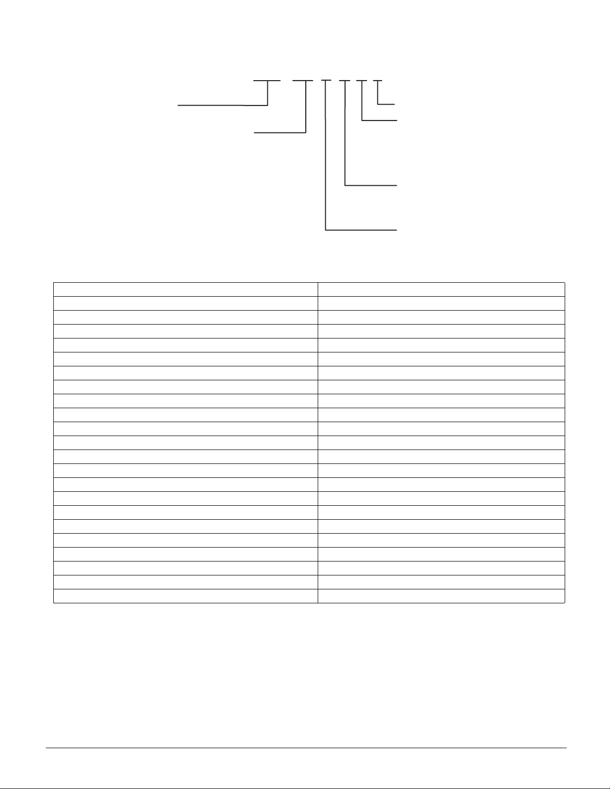
MODEL NOMENCLATURE
M
A
N
1
2
3
4
4
4
6
6
6
0*
A
*
odel
HP= Air Cooled Heat Pump
ominal Capacity (tons)
8 = 1-1/2
4 = 2
6 = 3
2 = 3-1/2
8 = 4
9 = 4
0 = 5
1 = 5
2 = 5
10 SEER Size 048 and 060 only.
Table 1: Unit Nameplate Model Number Identifier
Unit Nameplate McQuay Model Number
CPLE18-1C AHP018ARAY
CPLE24-1C AHP024ARAY
CPLE30-1C AHP030ARAY
CPLE36-1C AHP036ARAY
CPLE42-1C AHP042ARAY
CPLE48-1C AHP048ARAY
CPLE48-3C AHP048APAY
CPLE60-1C AHP060ARAY
CPLE60-3C AHP060APAY
CPLJ18-1B AHP018ARBY
CPLJ24-1B AHP024ARBY
CPLJ30-1B AHP030ARBY
CPLJ36-1B AHP036ARBY
CPLJ42-1B AHP042ARBY
CPLJ48-1B AHP048ARBY
CPLJ60-1B AHP060ARBY
CPLT24-1B AHP024ARCY
CPLT30-1B AHP030ARCY
CPLT36-1B AHP036ARCY
CPLT42-1B AHP042ARCY
CPLT48-1B AHP048ARCY
CPLT60-1B AHP060ARCY
AHP 018
RAY
Future Use
SEER
A = 10
B = 12
C = 13
Voltage/Phase
P = 208-230/3/6
R = 208-230/1/60
Vintage
IM-801 Page 3
Page 4
INTRODUCTION
General Description
These installation instructions cover the outdoor installation of
split system heat pumps from ½ to 5 tons. See the product catalog applicable to your model for information regarding specifications applicable to your model and accessories.
Receiving Inspection
McQuay products are carefully inspected prior to shipment
and the carrier has assumed responsibility for loss or damage
upon acceptance of the shipment.
Upon receiving your shipment, check all items carefully
against the Bill of Lading. Inspect the unit and/or accessories
for shipping damage as soon as they are received. Immediately file claims for loss or damage, either shipping or concealed, with the shipping company.
Check the unit nameplate to verify the model number and electrical characteristics are correct. In the event an incorrect unit
is shipped, it must be returned to the supplier and must NOT
be installed. The manufacturer disclaims all responsibility for
the installation of incorrectly shipped units.
Codes and Regulations
This product is designed and manufactured to permit installation in accordance with National Codes. System design
should, where applicable, follow information presented in
accepted industry guides such as the ASHRAE Handbooks. It
is the installer' s responsibility to install the product in accordance with National Codes and/or prevailing local codes and
regulations. The manufacturer disclaims all responsibility for
equipment installed in violation of any code or regulations.
IMPORTANT
The United States Environmental Protection Agency
(EPA) regulations cover introduction and disposal of
refrigerants in this unit. Failure to follow those
regulations can harm the environment and lead to
substantial fines. Because regulations can change, a
certified technician should perform any work done on
this unit. If you have any questions, please contact the
local office of the EPA.
Important Message to the Installer
This equipment is to be installed by an experienced installation
company and fully trained personnel. Carefully read all
instructions and take into account any special considerations
prior to installing the unit. Give this manual to the owner and
explain its provisions.
Important Message to the Owner
Read these instructions carefully and keep them near the product for future reference. Although these instructions are
addressed primarily to the installer, useful maintenance information is included. Have the installer acquaint you with the
operation of the product and periodic maintenance requirements.
Recognize Safety Symbols, Words, and Labels
The following symbols and labels are used throughout this
manual to indicate immediate or potential hazards. It is the
owner's and installer's responsibility to read and comply with
all safety information and instructions accompanying these
symbols. Failure to heed safety information increases the risk
of property damage and/or product damage, serious personal
injury or death. Improper installation, operation and maintenance can void the warranty.
DANGER
Immediate hazards which WILL result in property
damage, product damage, severe personal injury and/
or death.
WARNING
Hazards or unsafe practice CAN result in property
damage, product damage, sever personal injury and/or
death.
CAUTION
Hazards or unsafe practices which CAN result in
property damage, product damage, and/or personal
injury.
Replacement Parts
Replacement parts can be obtained by contacting McQuay at
1
-800-37-PARTS. When contacting McQuay for service or
replacement parts, refer to the model number and serial number of the unit as stamped on the nameplate attached to the
unit.
GENERAL WARNINGS
WARNING
Do not allow combustible materials, gasoline or other
flammable liquids or vapors in the vicinity of this unit.
Property damage, severe personal injury or death can
result. Identify all cut-off devices, switches, etc. that
serve your comfort equipment.
WARNING
Do not connect duct work to any other heat-producing
device such as fireplace insert, stove, etc. Such
connection can cause property damage, fire, carbon
monoxide poisoning, explosion, personal injury or
death.
SCROLL COMPRESSORS
Read the following before installing units with scroll compressors.
Pump Down Procedure
Scroll-equipped units should never be used to evacuate the air
conditiong system. Vacuums this low can cause internal electrical arcing, resulting in a damaged or failed compressor.
Crankcase Heater
Scroll-equipped units do not have, and do not require, a crankcase heater.
Unbrazing System Components
If the refrigerant charge is removed from a scroll equipped unit
by bleeding the high side only, it is sometimes possible for the
scrolls to seal, preventing pressure equalization through the
compressor. This may leave the low side shell and suction line
tubing pressurized. If a brazing torch is then applied to the low
side while the low side shell and suction line contains pressure,
Page 4 IM-801
Page 5
the pressurized refrigerant and oil mixture could ignite when it
escapes and contacts the brazing flame. To prevent this occurrence, it is important to check both the high and low side with
a manifold gauge before unbrazing, or in the case of repairing
a unit on an assembly line, bleed refrigerant from both the high
and low side.
WARNING
Before unbrazing, check pressure on both high and low
side. Incorrect charge removal can leave pressurized
refrigerant and oil, which can ignite in contact with
brazing heat, causing property damage and severe
personal injury.
INSTALLATION
The manufacturer intends this unit to be used only with components indicated. An improper match voids the warranty.
See the unit catalog for Performance Values and Approved
System Matches.
Pre-Installation Checkpoints
Perform pre-installation checkpoints before attempting any
installation. Consider the following check points:
• Structural strength of supporting members
• Clearances and provision for servicing
• Power supply and wiring
• Air duct connections
• Drain facilities and connections
Clearance
The outdoor heat pump unit is designed to be located outside
the building with unobstructed condenser air inlet and discharge. Additionally, the unit must be situated to permit access
for service and installation. Condenser air enters from three
sides. Air discharges upward from the top of the unit. Refrigerant tube electrical connections are made on the right side of
the unit as you face the compressor compartment. The best
and most common application is for the unit to be located 10”
from a back wall with the connection side facing the wall.
This “close to the wall” application minimizes exposed tubing
and wiring and reduces the space for children to run around the
unit, which can damage the tubes or wiring.
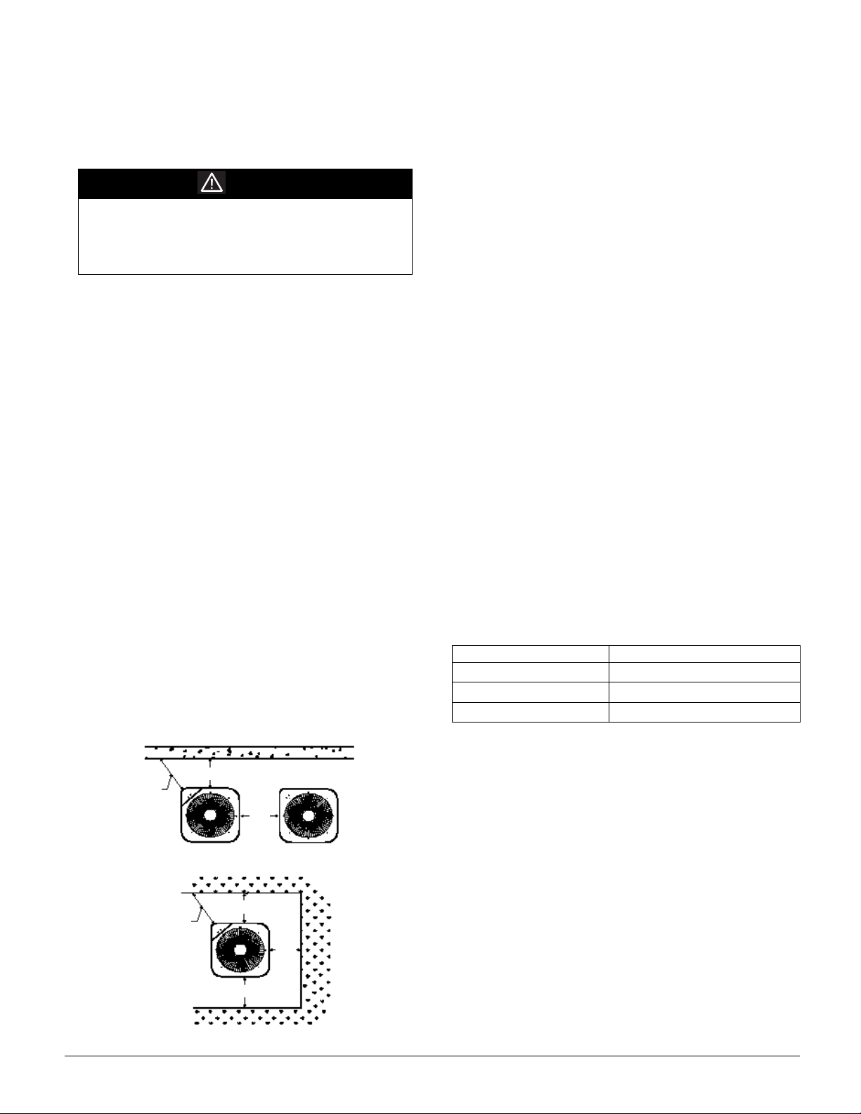
Figure 1. Clearances and Accessibility
10"
Service
Access
18" Min.
20"
Close to the wall application provides free, unobstructed air to
the other two sides. In more confined application spaces, such
as corners, provide a minimum 10” clearance on all air inlet
sides. Allow 18” minimum for service access to the compressor compartment and controls.
The top of the unit should be completely unobstructed. If units
are to be located under an overhang, there should be a minimum of 36” clearance and provisions made to deflect the
warm discharge air out from the overhang.
Location
Consider the effect of outdoor fan noise on the conditioned
space and any adjacent occupied space. Place the unit so the
discharge does not blow toward windows less than 25 feet
away.
Set the outdoor unit on a solid, level foundation - preferably a
concrete slab at least 4 inches thick. The slab should be above
ground level and surrounded by a graveled area for good drainage. Any slab used as a unit foundation should not adjoin the
building, as it is possible that sound and vibration may be
transmitted to the structure. For rooftop installation, use steel
or treated wood beams as a unit support for load distribution.
Heat pumps require special location consideration in areas of
heavy snow accumulation and/or areas with prolonged continuous subfreezing temperatures. Heat pump unit bases are cutout under the outdoor coil to permit drainage of frost
accumulation. The unit must be situated to permit free, unobstructed drainage of the defrost water and ice. A minimum 3"
clearance under the outdoor coil is required in the milder climates.
In more severe weather locations, elevate the unit to allow
unobstructed drainage and air flow. Table 2 lists recommended
elevation minimums:
Table 2: Elevation Minimums
Design Temperature Suggested Minimum Elevation
+15
-5
o
below -5
and above
o
to + 14
o
o
2 1/2"
8"
12"
Elevation Limitations
If the outdoor unit is mounted above the air handler, the maximum lift should not exceed 70 feet (suction line). If the air
handler is mounted above the outdoor unit, the lift should not
exceed 50 feet (liquid line).
Note: When installing systems where the indoor - outdoor
sections are separated by more than 15 feet, observe
the maximum elevation separations limitations.
Service
Access
18" Min.
IM-801 Page 5
10"
10"
10"
Page 6

Figure 2. Maximum Refrigerant Line Lengths
CONDENSING UNIT
PITCH SUCTION LINE TOWARD OUTDOOR
UNIT 1/2" FOR EVERY 10' OF LINE
LIQUID LINE
EVAPORATOR BLOWER
CCAUTION
Before starting equipment after prolonged shutdowns or at the time of initial start up, verify that the
circuits to the units are closed for at least 24 hours.
CONDENSING UNIT
ADDITIONAL SUCTION LINE OIL
70' MAX
CONDENSING UNIT
LIQUID LINE
SUCTION LINE OIL TRAPS WHEN INDOOR UNIT
IS 4 FEET OR MORE BELOW OUTDOOR UNIT
INVERTED LOOP
LIQUID LINE
SUCTION LINE
TRAP FOR EACH 20' RISE OF PIPE
EVAPORATOR BLOWER
EVAPORATOR BLOWER
8'
50' MAX
ELECTRICAL
WARNING
Before attempting any service or adjustments, lock
and tag out all gas and electrical supplies. Failure
to follow this warning can cause property damage,
personal injury and or death.
The supply power, voltage, frequency and phase must coincide
with those listed on the nameplate. Carefully check all wiring
against the manufacturer’s diagrams or with the diagram on
the unit’s access panel. Field wiring must be connected in
accordance with the National Code or other local codes that
may apply. Verify that the equipment is adequately grounded
per local code requirements. Use only copper wire between the
disconnect and unit.
Over-current protection less than what is recommended in the
unit catalog could result in unneccessary fuse failures and service calls. The manufacturer is not responsible for equipment
damage resulting from not using the recommended size protective devices as listed on the unit rating plate.
This unit has undergone a run test prior to packaging for shipment. This equipment has been started at minimum rated voltage and checked for satisfactory operation. Do not attempt to
operate this unit if the available voltage is not within the minimum and maximum shown on nameplate.
The condensing unit control wiring requires a 24-Volt minimum and a 40 VA service from the indoor transformer as
shown on the wiring diagram.
COMPONENTS
Contactor
This control is activated (closed) by the room thermostat for
both heating and cooling. It is de-energized (open) during
emergency heat. The contactor has a 24-Volt coil and supplies
power to the compressor and outdoor fan motor.
Crank Case Heater
The heater is factory wired so it is in operation whenever the
main power supply to the unit is “ON”. It warms the compressor crankcase, preventing liquid migration and subsequent
compressor damage. It is connected electrically to the contactor L1 and L2 terminals.
Condenser Motor
This is activated by the contactor during heating and cooling
except during defrost and emergency heat operation.
Compressor
This is activated by the contactor for heating and cooling
except during emergency heat. It is protected by an internal
overload device.
Defrost Control
This provides time/temperature initiation and termination of
the defrost cycle.
Loss of Charge Protector
If the system loses refrigerant charge, the control will open to
allow the compressor contactor to open.
Outdoor Thermostats
These optional controls are used to prevent full electric heater
operation at varying outdoor ambient (0°F to 45°F). They are
normally open above their set points and closed below to permit staging of indoor supplemental heater operation.
Reversing Valve Coil
This is activated by the thermostat (system’s switch) during
cooling only and during defrost. It positions the reversing
valve pilot valve for cooling operation.
PIPING
Once located, the outdoor unit is ready to be interconnected
with the indoor section, using the refrigeraion tubing sizes
noted in the “Long Line Recommendations” Table. Use only
refrigeration grade (dehydrated and capped) copper tubing.
CCAUTION
Keep refrigeration tubing clean and dry prior to and
during installation to avoid equipment damage.
Use insulation of at least 1/2” wall thickness on the vapor gas
line to prevent condensation when cooling and heat loss when
heating. Install the insulation on the tubing prior to unit instal-
Page 6 IM-801
Page 7

lation. Run the insulation the entire length of the installed line.
Cover the end of the tubing over which the insulation is
slipped so no foreign material is introduced to the interior of
the tubing. The outdoor units are equipped with two refrigerant line service valves. As shipped, the valves are in the frontseated or “down” position.
Line Set Installation Instructions
Use the following instructions to install line sets:
1. Cut tubing square. Verify it is round and free of burrs at the
connecting ends. Clean the tubing to prevent contaminants
from entering the system.
2. Wrap a wet rag around the copper valve stub before braz-
ing.
3. Braze or silver solder the joint.
4. After brazing, quench with a wet rag to cool the joint.
Evacuate and charge the connecting lines as outlined in
these instructions.
5. Remove the valve top cap. It is important to keep the cap
in a clean area to provide proper sealing once replaced.
6. Using a standard L-shaped Allen wrench, break open the
valve body. To expedite opening the valve body after it is
broken, use a ratchet wrench with a short Allen stub.
Please note that it is normal to see oil on the valve stem
body once the cap is removed.
7. Replace the valve cap and tighten with a wrench. Verify
that the the cap is sealed.
Table 3: Long Line Recommendations
REFRIGERANT LINE LENGTH (Ft)
Cond
Unit
Ton s
1 1/2 5/8 1/4 3/4 3/8 3/4 3/8
2 5/8 1/4 3/4* 3/8 3/4 3/8
2 1/2 3/4 3/8 3/4** 3/8 7/8 3/8
3 3/4 3/8 3/4** 3/8 7/8 3/8
3 1/2 3/4 3/8 7/8** 3/8 1 1/8 3/8
4 7/8 3/8 1 1/8 3/8 1 1/8 3/8
5 7/8 3/8 1 1/8 3/8 1 1/8 3/8
0-24 25-49 50-74***
Line Diameter (In. OD)
Suct Liq Suct Liq Suct Liq
* 7/8" required for full ratings
** 1 1/8" required for full ratings
EVAPORATOR COIL
CCAUTION
Evaporator coils are shipped under high pressure.
Use extreme care and follow the installation instructions provided with the evaporator coil to avoid personal injury.
The indoor coil is pressurized. The copper caps must be punctured to permit a gradual escape of the pressure prior to unsweating caps. Immediately couple the tubing to the indoor
unit to avoid exposing the coils to moisture. A properly sized
filter drier is furnished in the condenser. When heating the
copper to make solder connections, use a dry nitrogen flow
through the line to prevent oxidization inside of the copper.
Hard solder (Sil-Fos) is recommened, to provide a longer lasting joint.
INDOOR CFM AND HEATING
CAPACITY DETERMINATION
Prior to using the methods described below to check the system’s charge, it is important to verify the operating capacity of
the system and that the system is delivering sufficient air
across the indoor coil (CFM). The following procedures are
suggested methods for determining the system’s operating
capacity and CFM.
Airflow Determination - Indoor Coil
The heat pump system has been designed for optimum performance with an airflow across the indoor coil equaling approximately 400 CFM/TON (e.g. A 2 TON system should have 2 x
400 CFM/TON = 800 CFM). The system’s airflow can be
determined by several methods.
Airflow Test Instruments
There are a number of readily available instruments that can be
used in the field for airflow determination such as Barometers,
Volume-Aire Air Balancers, Anemometers, and Velometers.
When using these devices, it is important to follow the instructions provided by their manufacturer.
Temperature Rise Resistive Heat Method
Although it is not as accurate as the use of test equipment, the
Temperature Rise Method can be used to determine the indoor
airflow in a system employing electric resistance heat as the
backup heat source.The following formula is used:
WHERE
KW = The indoor section’s measured input = Volts x Amps
Volts = The measured Volts at the Indoor Section
Amps = The measured Amps at the Indoor Section
Temperature
Rise =
3413 = BTU per KW
1.08 = Specific Heat Air Constant
e.g. :
The input power to the indoor section = 10 KW
The Temperature Rise = 20°F
Refer to the Airflow Measurement Table.
Note: The compressor circuit (outdoor unit) must be
The temperature of the supply air - the temperature of
the return air
“OFF” so that the Temperature Rise measured
across the indoor unit is due only to the electric heat.
IM-801 Page 7
Page 8

Use the following instructions to determine the temperature
rise across the indoor section:
1. Use the same thermometer for the measuring the return and
supply air temperatures to avoid thermometer error.
2. Measure the temperatures within 6 feet of the indoor sec-
tion and downstream from any mixed air source. Verify
that the thermometer is not exposed to any radiant heat
areas.
3. Verify that the air temperature is stable before making mea-
surement.
Figure 3. Temperature Rise Measurement
Temperature Rise Heat Pump Only Method
The Temperature Rise Resistive Heat Method can be used to
determine the heating capacity of the heat pump system in the
heat pump “only” mode. The results obtained using this
method should agree within 10% of the data published in the
unit catalog for the combination of indoor and outdoor section.
Note: When using the following procedure to determine
the system’s capacity, verify that the indoor section
backup heat source is de-energized.
1. Use the same procedure described in the Temperature Rise
Resistive Heat Method to determine the system’s CFM and
temperature rise across the indoor section.
2. Determine the BTU output of the system for the measured
Temperature Rise and system CFM by using the following
formula:
BTU = CFM x TEMPERATURE x 1.08
Page 8 IM-801
Page 9

Table 4: Airflow Measurements
IM-801 Page 9
Page 10

REFRIGERANT CHARGE DETERMINATION AND ADJUSTMENT - HEAT
PUMP - COOLING CYCLE
Weigh In Charge Method
To verify that the heat pump system is properly charged,
weigh in the amount of refrigerant specified on the outdoor
section nameplate, with additional adjustments for line size,
line length and other system components. Heat Pump units are
supplied with an R-22 charge sufficient for a typical matching
evaporator and approximately 15 ft. of inner-connecting tubing. Systems having more than 15 ft of interconnecting refrigerant lines require an additional charge allowance of R-22.
Table 5: Line Charge Allowance (R-22-oz./lb.)
LINE O.D. (IN) LIQUID LINE SUCTION LINE
1/4 0.22
3/8 0.58
1/2 1.14
5/8 1.86 0.04
3/4 0.06
7/8 0.08
1 1/8 0.15
1 3/8 0.22
Superheat Method
The following information has been developed to determine
the proper charge for McQuay heat pump systems that are
already in operation.
Note: Many field variations exist that may affect the oper-
ating temperature and pressure readings of a heat
pump system. All McQuay heat pump systems use
fixed orifice refrigerant control devices. The following procedure has been developed for this type of
refrigerant control device.
1. With both base valves fully open, connect a set of service
gages to the base valves’ service ports, being careful to
purge the lines.
2. Allow the system to operate at least 10 minutes or until the
pressures stabilizes.
3. Temporarily install a thermometer on the suction (large)
line near the condensing unit base valve. Make sure that
there is good contact between the thermometer and the
refrigerant line and wrap the thermometer and line with
insulating tape to provide accurate readings.
4. Determine the systems superheat as follows:
a. Read the system’s suction pressure.
b. Using Table 6, determine the system’s saturated suction
temperature.
c. Read the suction line temperature.
d. The system’s superheat = the suction line temperature -
the saturated liquid temperature.
Table 6: Saturated Suction Pressure (R-22)
SUCTION PRESSURE PSIG
50 26
53 28
55 30
58 32
61 34
63 36
66 38
69 40
72 42
75 44
78 46
81 48
SATURATED SUCTION
TEMPERATURE
o
F
5. Adjust the charge as necessary by adding charge to lower
the superheat or bleeding the charge to raise the superheat.
Table 7: System Superheater.
AMBIENT CONDENSER INLET
TEMPERATURE
o
F DB
100
95
90
85
80
75 5 10172529
70 5 14202832
65 13 19 26 32 35
60 17 25 30 33 37
RETURN AIR TEMPERATURE
65 70 75 80 85
579
71218
5 101720
5 122126
o
F DB
55
CCAUTION
Remove the service gauge set from the lines carefully. Escaping liquid refrigerant can cause burns.
Expansion Valve System-Subcooling Charge
Method
1. Fully open both base valves.
2. Connect service gauge manifold to base-valve service parts
verify that lines are purged. Run system at least 10 minutes to allow pressure to stabalize.
3. Temporarily install the thermometer to liquid (small) line
near the condensing unit. Be sure that the contact between
thermometer and line is good. Wrap the thermometer with
insulating material to provide an accurate reading.
4. Referring to Table 8, adjust charge to obtain a temperature
12-15°F below the saturated liquid temperature.
Example:
If liquid pressure is 260 psig, refer to Table 8. 260 psig = 120°
saturated temperature. Subtract the liquid line temperature
obtained from thermostat connected to the liquid line. The liquid line temperature must be 12° - 15° cooler than the refrigeration saturation temperature. If the liquid line temperature is
warmer than 12° - 15°, add charge to decrease. If the temperature of the liquid line is cooler than 12° - 15°, recover charge
from the system.
Page 10 IM-801
Page 11
Table 8: Saturated Liquid Temperature
LIQUID PRESSURE PSIG
200 102
210 105
220 108
230 111
240 114
250 117
260 120
270 123
280 126
290 128
300 131
SATURATED TEMPERATURE
o
F
HEAT PUMP - HEATING CYCLE
As in the cooling mode, the proper method of verifying that
the system is properly charged is by weight, with the additional
charge adustments for line size, line length, and other system
components.
Hot Gas Method
The following procedure can be employed as a method to
check for system charge in the heating mode by measuring the
hot discharge gas at the compressor.
1. Allow the system to operate at least 20 minutes.
2. Attach and insulate an electronic thermometer probe to the
vapor service valve (large line) at the base valve.
NOTE - Make sure that the probe is well insulated from
the outdoor air.
3. Allow the system to operate at least 10 minutes. Then, use
an accurate electronic thermometer to measure the temperature of the discharge gas at the probe.
4. Using the electronic thermostat, measure the outdoor ambient temperature.
5. For verification, the temperature measured on the hot gas
line should be equal to the outdoor ambient temperature
plus 110°F +/- 4°F. (e.g: if the Outdoor Ambient is 45°F,
then the temperature measured by the thermometer probe
should be 155°F for a system that is properly charged). If
the temperature measured by the thermometer’s probe is
higher than the outdoor ambient plus 110°F, the system
charge should be adjusted by adding refrigerant to lower
the temperature. If the temperature measured is lower than
the outdoor ambient plus 110°F, the system charge should
be adjusted by recovering charge to raise the temperature
Note: When adjusting the charge in this manner, allow the
system to operate for at least 10 minutes before taking the next temperature reading.
STARTUP PROCEDURE AND CHECK
LIST
CCAUTION
Turn off power at all disconnects.
1. Set first-stage thermostat heat anticipator to .12 and turn
thermostat system switch to “COOL” and fan switch to
“AUTO”.
2. Turn cooling temperature setting as high as it will go.
3. Inspect all registers and set them to the normal open position.
4. Turn on the unit electrical supply at the fused disconnect
switch, both for the indoor unit and the outdoor unit.
5. Turn the fan switch to the “ON” position. The blower
should operate 10 to 15 seconds later.
6. Turn the fan switch to the “AUTO” position. The blower
should stop 90 seconds later.
Note: If outdoor temperature is below 55°F, proceed to
step 9. Do not check the cooling mode.
7. Slowly lower the cooling temperature until the first mercury bulb makes contact. The compressor, indoor blower,
and outdoor fan should now be running. Verify cool air is
being supplied by the unit.
8. Turn the system switch to “HEAT” and the fan switch to
“AUTO”.
9. Slowly raise the heating temperature setting. After the heating first-stage mercury bulb (upper) makes contact, stop
moving the lever. The compressor, indoor blower and outdoor fan should now be running. After giving the unit time
to settle out, verify heated air is being supplied by the
indoor unit.
10.If the outdoor ambient is above 70°F, the compressor may
trip on internal overload.
11.In the event that the outdoor ambient temperature is too
high to allow a thorough heating cycle check, postpone the
test until conditions are more suitable. However, do not fail
to perform a through heating cycle check.
12.If the unit operates properly on the heating cycle, raise the
heating temperature until the heating second-stage mercury
bulb (lower) makes contact.
13.Supplementary resistance heat, if installed, should now
come on. Verify it is operating correctly. If outdoor thermostats are installed, the outdoor ambient temperature must be
below the set point of these thermostats for heaters to operate. It may be necessary to jumper these thermostats to
check heater operation if outdoor ambient temperature is
mild.
14.For thermostats with an emergency heat switch, return to
Step #9. The emergency heat switch is located at the bottom of the thermostat. Move this switch to emergency heat.
The heat pump will stop, the indoor blower will continue to
run, all heaters will come on and the thermostat emergency
heat light will come on.
15.If checking the unit on the heating cycle in the winter
(when the outdoor coil is cold enough to actuate the defrost
control), observe at least one defrost cycle to verify that the
unit defrosts properly.
16.Check to see if all supply and return air grilles are adjusted
and the air distribution system is balanced for the best compromise between heating and cooling.
17.Check for air leaks in the ductwork.
IM-801 Page 11
Page 12

18.Verify that the heat pump is free of “rattles” and the tubing
in the unit is free from excessive vibration. Also verify that
tubes or lines are not rubbing against each other, sheet
metal surfaces or edges. If so, correct the issue.
19.Set the thermostat at the appropriate setting for cooling and
heating or automatic changeover for normal use.
20.Instruct the owner on the unit operation, filter servicing,
correct thermostat operation, etc. The foregoing “Start-up
Procedure and Check List” is recommended to serve as an
indication that the heat pump system will operate normally.
OPERATION - DEFROST CONTROL
Timing
When operating, the power to the circuit board is controlled by
a temperature sensor that is clamped to a return bend on the
outdoor coil. Timing periods of 30, 60, or 90 minutes may be
selected by connecting the circuit board jumper wire to 30, 60
or 90 respectively. Accumulation of time for the selected timing period begins when the sensor closes (approximately 28°F)
and when the wall thermostat is calling for heat. At the end of
the timing period, a defrost cycle will be initiated, provided the
sensor remains closed. When the sensor opens (approximately
65°F), the defrost cycle is terminated. If the defrost cycle is not
terminated due to the sensor temperature, a 10 minute override
interrupts the defrost period.
apply to the heat pump when it is on the cooling cycle. Most
apply to the heating cycle, except that “condenser” becomes
“evaporator”, “evaporator” becomes “condenser” and “cooling” becomes “heating”. When the heat pump is on the heating cycle, it is necessary to redirect the refrigerant flow
through the refrigerant circuit external to the compressor. This
is accomplished with a reversing valve. Thus, the hot discharge vapor from the compressor is directed to the inside coil
(evaporator on the cooling cycle) where the heat is removed,
and the vapor condenses into liquid. It then goes through a
capillary tube, or expansion valve, to the outside coil (condenser on the cooling cycle) where the liquid is evaporated,
and vapor goes to the compressor.
When the solenoid valve is operated either from heating to
cooling or vice versa, it moves the pilot valve, thus putting
suction pressure (low pressure) on one side of the piston of the
reversing valve. Because discharge pressure (high pressure) is
on the other side of the piston, the piston slides to the low pressure side and reverses the flow of the refrigerant in the circuit.
The following figures show a schematic of a heat pump on the
cooling cycle and the heating cycle.
Figure 4. Heat Pump Refrigeration Circuit
Field Testing / Trouble Shooting
A. Run unit in heat mode.
B. Check unit for proper charge. Note: Bands of frost indicate
low refrigerant charge
C. Shut off power to unit.
D. Disconnect outdoor fan by removing the purple lead from
“DF2” on defrost control.
E. Restart unit and allow frost to accumulate.
F. After a few minutes of operation, the defrost thermostat
should close. To verify this, check for 24 volts between
“DFT” and “C” on the board. If the temperature at the thermostat is less than 28°F and the thermostat is open, replace
the thermostat as it is defective.
G. When the defrost thermostat has closed, short the “test”
pins on the board until the reversing valve shifts, indicating
defrost. This could take up to 21 seconds depending on
what timing period the board is set on. After defrost initiation, the short must instantly be removed or the defrost
period will only last 2.3 seconds.
H. After the defrost has terminated, check the defrost thermo-
stat for 24 volts between “DFT” and “C”. The reading
should indicate 0 volts (open sensor).
I. Shut off power to unit.
J. Replace the outdoor fan motor lead and turn on the power.
General Explanation and Guidance
The heat pump operates similar to a summer air conditioning
unit when it is on the cooling cycle. Therefore, all of the charts
and data for service that apply to summer air conditioning also
Page 12 IM-801
In addition to a reversing valve, a heat pump is equipped with
an expansion device and check valve for the inside coil, and
similar equipment for the outside coil. It is also provided with
a defrost control system.
Page 13

The expansion device performs the same function on the heating cycle as on the cooling cycle. The check valves are
required due to the reverse flow of refrigerant when changing
from cooling to heating or vice versa.
When the heat pump is on the heating cycle, at which time the
outdoor coil is functioning as an evaporator, the temperature of
the refrigerant in the outdoor coil must be below the temperature of the outdoor air in order for the refrigerant in the outdoor
coil to extract heat from the air. Thus, the greater the difference
in outdoor temperature and outdoor coil temperature, the
greater the heating capacity of the heat pump. Since this is
characteristic of heat pumps, it is good practice to provide supplementary heat for all heat pump installations in areas where
the temperature drops below 45°F. It is also good practice to
provide sufficient supplementary heat to handle the entire heating requirements in case of a of heat pump failure (e.g. a compressor failure, refrigerant leak, etc).
Because the temperature of the liquid refrigerant in the outdoor
coil during the heating cycle is generally below the freezing
point, frost forms on the surfaces of the outdoor coil under certain weather conditions of temperature and relative humidity.
Therefore, it is necessary to reverse the flow of refrigerant to
provide hot gas in the outdoor coil and melt the frost accumulation. This is accomplished by reversing the heat pump to the
cooling cycle. At the same time, the outdoor fan stops to hasten the temperature rise of the outdoor coil and lessen the time
required for defrosting. The indoor blower continues to run
and the supplementary heaters are energized.
MAINTENANCE
General
Outdoor units do not require a planned maintenance program
under normal operating conditions. However, not less than
once each cooling season, the unit should be inspected and, if
necessary, cleaned. Particular attention should be given to the
air inlet side of the outdoor coil to verify that leaves, grass,
etc., are not being drawn into the unit. Restricting air flow
across the coil will result in loss of system capacity, high operating pressures and excessive operating costs. If the outdoor
unit is installed adjacent to a grassy area, lawn mowers should
be routed so the discharge of the mower will be directed away
from the unit. Air filters must be installed in the system at
some point upstream to the indoor coil. Inspect and, if necessary, replace and/or clean air filters at least once a month.
If disposable filters are used, an adequate supply of clean,
unused filters of the correct size should be available.
CCAUTION
Equipment should never be operated without filters.
Permanent type filters may be vacuumed and/or washed; but
they should not be reinstalled until thoroughly dry. Most air filters are marked to indicate the direction of airflow and this
should be carefully noted when they are being installed.
CCAUTION
Never turn a dirty filter to allow airflow in the opposite direction.
The blower and motor bearings are permanently lubricated and
do not require additional lubrication.
The owner should have at least one set of replacement fuses of
the size supplied with the original equipment.
CWARNING
Do not replace fuses with sizes other than those
supplied. Improper current protection can cause
equipment damage, severe personal injury or death.
Common Causes of Unsatisfactory Operation of
Heat Pumps on the Heating Cycle
A. Dirty filters or inadequate air volume through the
indoor coil. When the heat pump is on the heating cycle,
the indoor coil is functioning as a condenser. Therefore, the
filters must always be clean and sufficient air volume must
pass through the indoor coil to prevent excessive discharge
pressure and high-pressure cutout.
B. Outside air into return duct. Cold outside air should not
be introduced in the return duct close enough to the indoor
coil to reduce temperature of the air entering the coil below
65°F during the heating cycle. Air below this temperature
will cause low discharge pressure, low suction pressure and
excessive defrost cycling that will result in low heating output. It may also cause false defrosting.
C. Undercharge. Undercharge on the heating cycle will cause
low discharge pressure, resulting in low suction pressure
and frost accumulation on the lower part of the outdoor
coil.
D. Poor “terminating” defrost thermostat contact. The
defrost thermostat must make good thermal contact on the
return bend. Otherwise, it may not terminate the defrost
cycle quickly enough to prevent the unit from cutting out
on high discharge pressure during the defrost cycle.
E. Causes of Malfunctioning Reversing Valve:
1. Solenoid not energized. In order to determine if the
solenoid is energized, touch the nut that holds the solenoid cover in place with a screwdriver. If the nut magnetically holds the screwdriver in the Cooling mode,
the solenoid is energized.
2. No voltage to solenoid. Check the voltage and if there
is no voltage, check the wiring circuit.
3. Valve will not shift:
a. Undercharged: check for leaks.
b Valve Body Damaged: Replace valve.
c. Unit Properly Charged: If it is on the heating
cycle, raise discharge pressure by restricting airflow through the indoor coil. If the valve does
not shift, tap it lightly on both ends with a screwdriver handle.
IM-801 Page 13
Page 14
WIRING DIAGRAM
C M O U T D O O R F A N M O T O R
C O M P C O M P R E S S O R
C C O N T A C T O R
D C D E F R O S T C O N T R O L
L V D R L O W V O L T A G E D E F R O S T D E L A Y
C H C R A N
K C A S E H E A T E R
I O I N T E R N A L O V E R L O A D
L P L O W P R E S S U R E S W I T C H
O T O U T D O O R T H E R M O S T A T ( O P T I O N A L )
R C C F R U N C A P A C I
T O R F O R C O M P R E S S O R A N D F A N
D F T D E F R O S T T H E R M O S T A T
R V C R E V E R S I N G V A L V E C O I L
S C S T A R T C A P A C I T O R F O R C O M P R E
S S O R ( O P T I O N A L )
S R S T A R T R E L A Y F O R C O M P R E S S O R ( O P T I O N A L )
H V D R H I G H V O L T A G E D E F R O S T R E L A Y
L 2
C
T 2
S C
R C C F
1
S R
S
C O M P .
M A I N
S E E R A T I N G P L A T E
O U T D O O R P O W E R S U P P L Y
5 2
T 1
C
L 1
C
D F 1
H V D R
F
( I F U S E D )
S T A R T A S S I S T
A U X
I O
C
C O N T A C T O R
D O U B L E P O L E
A L T E R N A T E
D F 2
C M
C H
A U X
M A I N
I O
O
B L
Y
C
D C
Y
( I F U S E D )
D F T
L V D R
D F T
R
C
Y
R V C
L P
Y
O
W 2
R
W 2
O
O
R
N O T E S :
I N D O O R P O W E R S U P P L Y
N I T
T F A C T O R Y E Q U I P P E D
2 . S E E I N D O O R A N D O U T D O O R U
T H E R M O S T A T .
T E R M I N A L B L O C K A N D I N D O O R
1 . T O I N D O O R U N I T L O W V O L T A G E
3 . S T A R T A S S I S
O U T D O O R T H E R M O S T A T .
C O N N E C T I O N O F O P T I O N A L
I N S T A L L A T I O N I N S T R U C T I O N S F O R
W H E N R E Q U I R E D .
O T - 1
P U
D F 2
H V D R
L V D R
D C
O T - 2
R
D F 1
W
D F T
O O W 2 R R
C Y
B K
O
B L
R
O T - 3
Y
W 2
W
S E E N O T E 2
R
B L
Y
R
D F T
R
Y
Y
L P
Y
B R
B K
B K
R
B K
Y
Y
C
O
R
C O M P O N E N T C O D E
W I R I N G C O D E
N O T E 1
T 1 T 2
R
T 2
T 1
Y
Y
B R
R
R
C O N T R O L B O X
F A C T O R Y W I R I N G F I E L D W I R I N G
E R N A T E
L 1 L 2
A L T
C
B K
B K
B K
C O N T A C T O R
D O U B L E P O L E
L 2
L 1
B L
P O W E R S U P P L Y
( S E E R A T I N G P L A T E )
U S E L 1 F O R N E U T R A L O R
B L
G R O U N D S U P P L Y I F U S E D
U S E C O P P E R C O N N E C T O R S O N L Y
Y
R
H I G H V O L T A G E H I G H V O L T A G E
L O W V O L A G E L O W V O L T A G E
O P I O N A L H I G H V O L T A G E
O P T I O N A L S T A R T A S S I S T
Y
S T A R T A S S I S T
R V C
B K B K
M A I N
E Q U I P M E N T G R O U N D U S E
C O M P .
A U X
R
C S
Y
C O P P E R C O N D U C T O R S O N L Y
R
B R
P U
A U X
M A I N
A N D T H E R M O S T A T I N " O F F " P O S I T I O N
C O N T R O L S S H O W N W I T H U T I L I T I E S I N " O N " P O S I T I O N
C H
( C R A N K C A S E H E A T I F U S E D )
B K
B K
B K
I O
C M
B K
1
S R
5
2
R
B L
S C
B L A C K
C O L O R C O D E
B K
P U R P L E
R E D
R
B R O W N
O R A N G E
B L U E
Y E L L O W
Y
B L
W H I T E
B R
P U
U S E N . E . C . C L A S S 2 W I R E
O
W
Page 14 IM-801
Page 15

THERMOSTAT DIAGRAM
e
SYSTEM COMPOSITE DIAGRAM
SAH018 to 060
18-60
10 KW & BELOW
Heat Pump
W2
C
OYR
BL
OR
W
R
Y
R
Y
OR
W
BL
Outdoor Thermostat
(optional) Make On Fall
SAH018 to 060
SYSTEM COMPOSITE DIAGRAM
18-60
10 KW & BELOW
Heat Pump
W2
C
OYR
BL
OR
W
R
Y
R
Y
OR
W
BL
OT1
Note
OT2
#18GA. 7 Wire Needed When 2
Outdoor Thermostat Are Used
Conventional
Room Thermostat
O
#18 GA. 5 Wire
Room Thermostat
O
#18 GA. 5 Wire
W2
CY
GE
R
R
GR
See
BL
Note 3
BR
W
BL
#18GA. 6 Wire Needed When
Outdoor Thermostat Is Used
Conventional
CY
W2 G E
See
Note 3
R
GR
See
Note 2
W
1
EHR
2
4
3
BL
BR
#18 GA. 7 Wire
Pink
#18 GA. 7 Wire
AR Indoor Unit
Pink
R
NOTES:
1. Outdoor Thermostat (OT1) should be the first
to close and the first to open.
2. Install jumper if Outdoor Thermostat (OT2) is
not used.
NOMENCLATURE :
OT - Outdoor Thermostat (Optional)
MOF - Make On Fall
EHR - Emergency Heat Relay (Optional)
COLOR CODES
R - Red OR - Orang
Y - Yellow W - White
BL - Blue G- Green
BR - Brown
3. Remove wire when using Outdoor Thermostat.
#18 Ga. 7 wire needed when (2) OTs are used.
IM-801 Page 15
Page 16

This document contains the most current product information as of this printing. For the most up-to-date
product information, please go to www.mcquay.com.
www.mcquay.com • 800-432-1342
 Loading...