

McIntosh MC901 Owner's Manual

McIntosh Laboratory, Inc. 2 Chambers Street Binghamton, New York 13903-2699 Phone: 607-723-3512 www.mcintoshlabs.com
MC901
Dual Mono Amplier
Owner’s Manual

The MC901 Dual Mono Amplifier is the first of its
kind Amplifier drawn from McIntosh’s long tradition of
uncompromising tube and solid-state Amplifiers. The
MC901 combines the finest aspects of tube and solidstate Amplifiers to drive even the most power-hungry
Loudspeakers to peak performance.
Safety First
Please read all the enclosed MC901 SAFETY
INFORMATION included in separate documents.
You can never be too safe.
2

Thank you from all of us at
McIntosh
You have invested in a precision instrument that will
provide you with many years of enjoyment. Please
take a few moments to familiarize yourself with
the features and instructions to get the maximum
performance from your equipment.
If you need further technical assistance, please contact
your dealer who may be more familiar with your
particular setup including other brands. You can also
contact McIntosh with additional questions or in the
unlikely event of needing service.
McIntosh Laboratory, Inc.
2 Chambers Street
Binghamton, New York 13903
Technical Assistance: (607) 723-3512
Customer Service: (607) 723-3515
Fax:(607) 724-0549
Email: support@mcintoshlabs.com
Website: mcintoshlabs.com
Make a Note
For future reference, you can jot down your serial
number and purchase information here. We can
identify your purchase from this information if the
occasion should arise.
Serial Number:
Purchase Date:
Dealer Name:
Table of Contents
Safety First ............................................................. 2
Thank you from all of us at McIntosh ................... 3
Make a Note ........................................................... 3
One of a Kind ........................................................ 4
What is in the box .................................................. 5
Where to put it ....................................................... 5
Removal of Foam Inserts over Vacuum Tubes ...... 5
Rear Connections and Switches ............................ 6
Connections on the Back ....................................... 7
AC Power .......................................................... 7
Input Mode ........................................................ 7
Input Select Switch ........................................... 7
Balanced and Unbalanced Inputs ..................... 7
Composite or Direct Inputs ............................... 7
Power Control .................................................. 8
Auto Off Switch ................................................ 8
Connecting a Speaker ............................................ 8
A Question of Impedance ................................. 8
The Speaker Wire ............................................. 8
The Output Terminal Hookup .......................... 8
Remove Loudspeaker Jumpers .............................. 9
Sentry Monitor ..................................................... 10
Quad Balanced..................................................... 10
Circuit Breaker .................................................... 10
MC901 Connection Diagram ............................... 11
Setting the Filters ................................................. 12
Low Pass Filter ............................................... 12
High Pass Filter .............................................. 12
Setting the Level Adjust ...................................... 12
Vacuum Tubes Used in the MC901 ..................... 12
The Front of the MC901 ...................................... 13
The Dual Meter ............................................... 13
Meter Control Knob ........................................ 14
Power Control Knob ....................................... 14
Power Guard LED........................................... 14
Power Guard Screen Grid Sensor (SGS) LED 14
Repacking the MC901 .........................................15
Roll-off for Crossover Points .............................. 16
Roll-off for 1K Crossover Point ...........................18
Solid State Specifications ....................................19
Vacuum Tube Specifications ...............................19
General Specifications ......................................... 19
List of Figures
Figure 01– Removing Tube Cover Screws ........... 5
Figure 02– Remove Protective Foam ................... 5
Figure 03– Tubes Revealed ................................... 5
Figure 04– Rear View ..........................................6
Figure 05– XLR Pin Configuration ..................... 7
Figure 06– Power Control (trigger) mini plug ...... 8
Figure 07– Loudspeaker Wire Gauge Guide ........ 8
Figure 08– Opening Output Terminal .................. 9
Figure 09– Tightening Output Terminal ............. 9
Figure 10– Terminal Connection Covers ............. 9
Figure 11– Terminal Connection Cover openings 9
Figure 12– Circuit Breaker ................................. 10
Figure 13– MC901 Connection Diagram ........... 11
Figure 14– EQ Knobs ........................................ 12
Figure 15– Vacuum Tube Positions .................... 13
Figure 16– Dual Meter ....................................... 13
Figure 17– Front Knobs and LEDs ..................... 14
Figure 18– Roll-Off for Low Pass Filter ............ 16
Figure 19– Roll-Off for High Pass Filter ........... 17
Figure 20– 1K Roll-off Combined Graph .......... 18
Copyright 2019 © by McIntosh Laboratory, Inc
3

One of a Kind
The MC901 Dual Mono Amplier has been
designed to be the ultimate solution for bi-amping
Loudspeakers. It’s the best answer in the quest to
capture the harmonic beauty of Vacuum Tubes for
a Loudspeaker’s mid and upper registers while still
having an abundance of power dedicated to the powerhungry woofers. To bi-amp in the past, two separate
Ampliers were required, but now the MC901 does
the work of two separate Ampliers with its optimized
combination of a Tube and a Solid State Amplier
happily co-existing as a single optimized instrument.
Previously, crossover points would have to be handled
outside of the Amplier and a lot of trial and error
would be required to properly setup two Ampliers
that were not designed to work together.
The MC901 is the perfect solution for bi-amping
speakers. 300 Watts of Vacuum Tube power are
available to drive your Loudspeaker’s midranges and
tweeters. Vacuum Tubes do not perform optimally
when amplifying frequencies that are not used by
the Loudspeaker. To maximize the Tubes’ power, the
MC901’s internal, adjustable crossover assures the
Tubes will only be powering the frequencies that the
Loudspeakers will be reproducing. With the MC901,
the Tubes will not be challenged or overloaded by
low-end reproduction because the Solid State section
has 600 Watts dedicated to driving the low end, and
the adjustable lters assure that each Amplier section
handles only the frequencies that they are intended
to amplify. Full power of each Amplier section
is available whether you are using 2, 4 or 8 Ohm
Loudspeakers thanks to our Unity Coupled Circuit
Output Transformer and Autoformer™.
McIntosh’s Unity Coupled Circuit Output Transformer
solved problems that had long plagued Vacuum Tube
Ampliers. By employing a complex hand-wired
transformer design, the Unity Coupled Circuit Output
Transformer turned what had been a problem of
capacitance between two wires into a conguration
where the two wires support the transformer’s
performance. Furthermore, the complete coupling of
both halves of the transformer prevents the collapse of
the magnetic eld, which is an issue for other Vacuum
Tube Amplier designs. The Unity Coupled Circuit
also eliminated the switching error between positive
and negative halves, freeing the Tube Amplier of a
sloppiness heard in other unsuccessful congurations.
On the Solid State side, the MC901 utilizes our
Autoformer, which provides the optimal method of
connecting a Solid State Amplier to a Loudspeaker
of virtually any impedance. The McIntosh Autoformer
provides full power to the Loudspeaker regardless if
it has 2, 4 or 8 Ohm impedance while offering DC
current protection to the valuable Loudspeakers. The
Quad Balanced design of the MC901 works with
the Autoformer to combine two out of phase audio
signals. The two out of phase signals are magnetically
combined in the Autoformer where one signal is
inverted back into phase with the other signal. During
this process, any distortion in either signal will be out
of phase with the other signal and cancelled. While
distortion is cancelled, the power will be summed
due to the unique properties of the hand-wiring of the
McIntosh Autoformer, and the newly combined signal
will be twice the power of the individual signals.
®
Power Guard
monitors and adjusts the input signal in
the 600 Watt solid state amplier section in real time,
then makes unobtrusive adjustments to prevent harsh
sounding distortion and potential speaker damaging
clipping. The 300 Watt Vacuum Tube amplier section
of the MC901 breaks new ground as it’s our rst
amplier to feature our new Power Guard Screen Grid
Sensor™ (SGS) technology. Power Guard SGS™
helps prevent premature Vacuum Tube failure by
monitoring the screen grid current in the KT88 output
Vacuum Tubes. If the current becomes too high, a
circuit in Power Guard SGS is activated which then
dynamically attenuates the input signal in real time to
keep the Vacuum Tubes operating at safe levels.
The Solid State and Tube Amplier sections of the
MC901 are engineered to function in tandem, with
each specically designed to perform its role. Fine
tuning your system is made simple with variable
Low Pass and High Pass Filters. This allows you
to compliment the crossover settings of your
Loudspeakers and maximize the power available to
each frequency range. Relative gain levels for each
section can be adjusted from -6dB to + 3dB, or you
can connect a direct feed to each Amplier section and
bypass all the lters. This is perfect if you have room
correction and crossovers external to the MC901.
McIntosh is uniquely positioned to create the MC901.
McIntosh has a 70-year track record of producing
award-winning Solid State and Vacuum Tube
Ampliers utilizing our patented technologies. The
MC901 builds upon this foundation and expands this
legacy of quality and cutting-edge innovations. That is
why only McIntosh could have developed the one-ofa-kind MC901.
4

What is in the box
Here is what is in the box besides all the shipping foam:
One MC901 Dual Mono Amplier
One manual package including this manual
Two Terminal Connection Covers
One AC Power Cord
One McIntosh Output Terminal Wrench
Where to put it
First, you must acknowledge that the MC901 is VERY
HEAVY. When moving the unit, have enough help to
lift the MC901. This will ensure the safety of both you
and the MC901.
The MC901 should be installed upright on the oor
or amplier stand. Adequate ventilation is important
and will aid in a long trouble-free life of the MC901.
Enclosures are not recommended, but if you wish to
enclose the MC901, you must ensure proper airow
and allow at least 19 inches (48.3cm) above the unit
and 6 inches (15.2cm) for the front, rear and sides. Do
not remove the feet and make sure there is nothing
obstructing the airow beneath the MC901. There
must be openings for the warm air to escape above the
unit and a fan would aid in this regard.
Removal of Foam Inserts over
Vacuum Tubes
IMPORTANT!
REMOVE THE FOAM INSERTS OVER THE
• To prevent damage to the Tubes during
shipping, there are special foam inserts
surrounding the Tubes of the Power Amplier
• The Foam Inserts must be removed from
the MC901 before connecting the AC Power
Supply Cord to the Power Amplier
• Failure to do so has the potential of a Fire
Hazard, resulting in damage to the MC901
and the surrounding environment
• Follow these instructions for removal of
the packing foam before connecting the AC
Power Supply Cord to the MC901
To remove the protective foam, it is necessary to
temporarily remove the two Tube Covers. To remove
each Tube Cover:
• Use a Phillips Head #2 screw driver to remove
the two screws that hold each of the Tube
Covers (Figure 01)
• Pull the Tube Cover slightly outward from the
center of the MC901 to clear the lip covering
the top edge of the Tube Cover, and then lift
upward (Figure 02)
• Pull the protective foam straight up off the
Vacuum Tubes (Figure 02)
• Replace the Tube Cover
• Replace the two screws to secure the cover
(Figure 01)
• Do this procedure for each of the two Tube
Covers
Save the protective foam and warning label for
possible future use.
Figure 01– Removing Tube Cover Screws
Figure 02– Remove Protective Foam
VACUUM TUBES PRIOR TO CONNECTING
THE A.C. POWER SUPPLY CORD.
Figure 03– Tubes Revealed
5
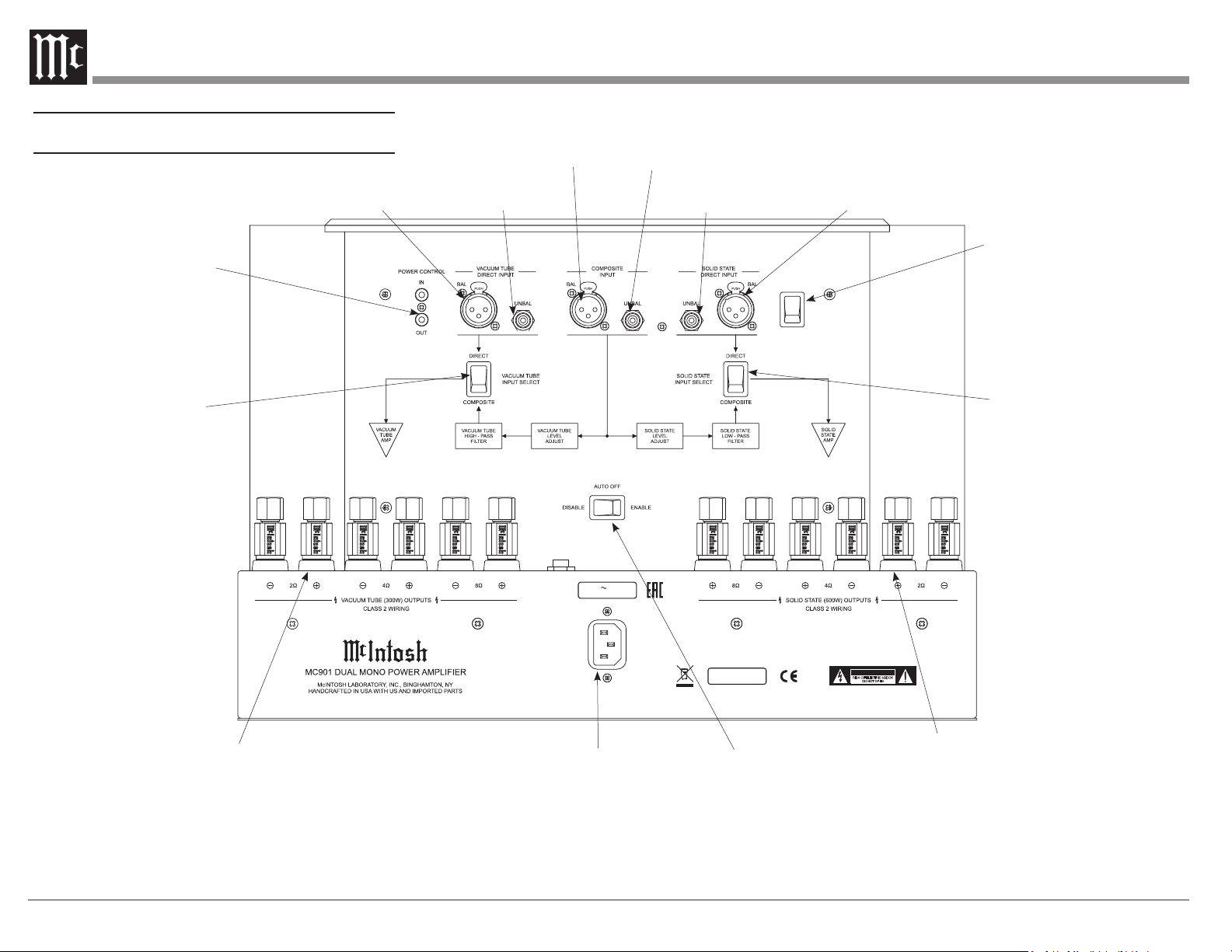
Rear Connecons and Switches
VACUUM TUBE DIRECT INPUT
BAL (Balanced) or UNBAL (Unbalanced)
POWER CONTROL
IN and OUT for On/Off
signals to (OUT) and
from (IN) other McIntosh
Components
COMPOSITE INPUT
BAL (Balanced) or UNBAL (Unbalanced)
SOLID STATE DIRECT INPUT
UNBAL (Unbalanced) or BAL (Balanced)
INPUT MODE
BALANCED
UNBALANCED
INPUT MODE Switch
Used to select
BALANCED or
UNBALANCED inputs
VACUUM TUBE INPUT
SELECT Switch
Used to select DIRECT
or COMPOSITE input
for the Vacuum Tube
Amplier
VACUUM TUBE (300W) OUTPUTS
Terminals for connecting Speaker Wire
from a Loudspeaker to the Vacuum Tube
Amplier. Positive (+) and Negative
(-) terminals for 2, 4 and 8 Ohm
connections
AC POWER
Use supplied AC Power Cord
to connect to a live AC outlet
after other connections have
been made
Figure 04– Rear View
CIRCUIT
BREAKER
120V 50/60Hz
12 AMPS
SERIAL
NUMBER
CAUTION
RISK OF ELECTRIC SHOCK
DO NOT OPEN
ATTENTION: RISQUE DE CHOC ELECTRIQUE-NE PAS OUVRIR
AUTO OFF
When ENABLE is selected,
the MC901 will power off
after 30 continuous minutes
of receiving no signal.
DISABLE will defeat this
feature
SOLID STATE INPUT
SELECT Switch
Used to select DIRECT
or COMPOSITE input for
the Solid State Amplier
SOLID STATE (600W) OUTPUTS
Terminals for connecting Speaker
Wire from a Loudspeaker to the
Solid State Amplier. Positive (+)
and Negative (-) terminals for 2, 4
and 8 Ohm connections
6
 Loading...