

Page 1

MAINTENANCE
MANUAL
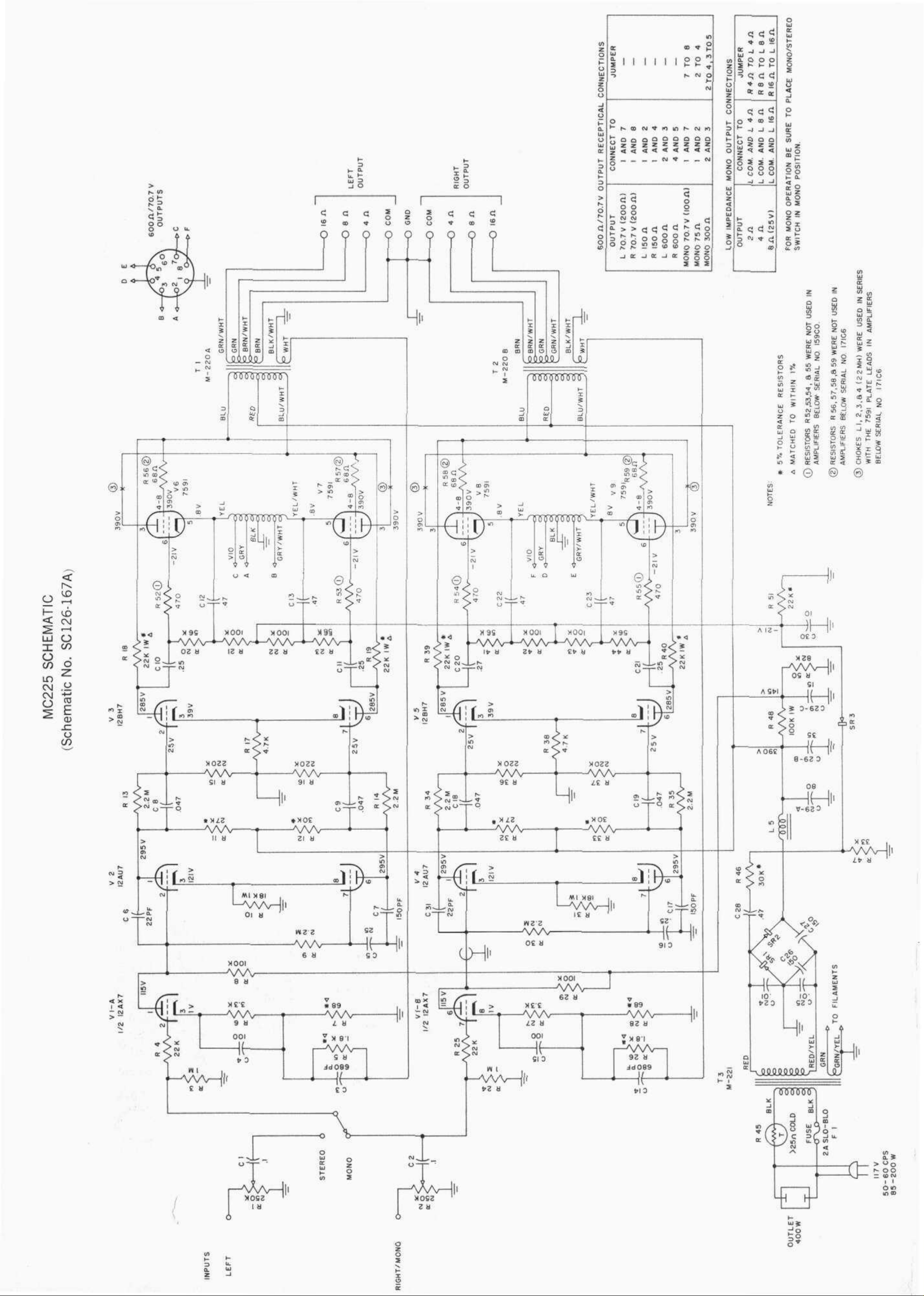
MC225
STEREO
POWER AMPLIFIER
(Serial Nos. 100C1 & above)
Page 2
Page 3

Table 1. MC225 VOLTAGE AND RESISTANCE CHART
(Schematic No. SC126-167A)
Tube
12AX7
(VI)
12AU7
(V2 or V3)
12BH7
(V4 or V5)
7591
(V6,
V7, V8, or V9)
Pin No.
1
2
3
4
5
6
7
8
9
1
2
3
4
5
6
7
8
9
1
2
3
4
5
6
7
8
9
1
2
3
4
5
6
7
8
DC Volts
115
0
1
FIL
FIL
115
0
1
FIL
295
115
121
FIL
FIL
295
100
121
FIL
285
25
39
FIL
FIL
285
25
39
FIL
FIL
390
390
0.8
-21
FIL
390
Resistance in
Ohms, Unit Off
180K
1M
3.3K
0
0
180K
1M
3.3K
0
27K*
180K
18K
0
0
30K*
2.4M
18K
0
22K*
220K
4.7K
0
0
22K*
220K
4.7K
0
0
62*
130*
40
180K
0
130*
This
Resistance
measured
to
positive side
of B+
rectifier SR2. Warning:
Discharge filter condensers before making measurements.
A high resistance VTVM is used for all measurements, voltages and resis-
tances are to ground except as noted.
Page 4

Special components used in the MC225 are listed below.
These components are designed and built specifically for
the MC225. They may be purchased directly from Customer
Service, Mclntosh Laboratory Inc. When you order parts be
sure to give the SCHEMATIC NO. and DESCRIPTION from
Table 2 below, and serial and model number for your am-
plifier.
Table 2. MC225 SPECIAL COMPONENTS
(Schematic No. SC126-167A)
COMPONENT NO.
C29A, B, C
L5
R45
SR1,
SR2
SR3
Tl
T2
T3
DESCRIPTION
Filter Capacitor, 80-35/15 MF 500/450 V
Choke, Filter
Thermistor
Silicon Rectifier, 500PIV, 500 MA
Selenium Rectifier, 400 PIV, 75 MA
Output Transformer, Type M-220A
Output Transformer, Type M-220B
Power Transformer, Type M-221
2M-AA126-170
LABORATORY INC.
2 CHAMBERS STREET, BINGHAMTON, N. Y.
Made in U.S.A.
Phone-Area Code 607 723-5491
 Loading...