

Page 1
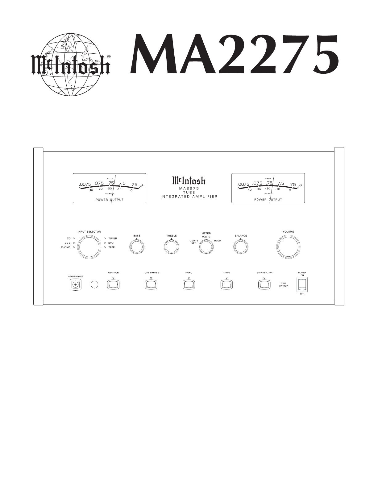
TUBE
INTEGRATED AMPLIFIER
CONTENTS
Performance Specifications ........................................ 2
Notes ......................................................................... 2
Rear Panel .................................................................. 3
Section Location ........................................................ 4
Block Diagram ...................................................... 5 - 7
Interconnection Diagram .................................... 8 - 10
Main Schematic and PCB................................. 11 - 16
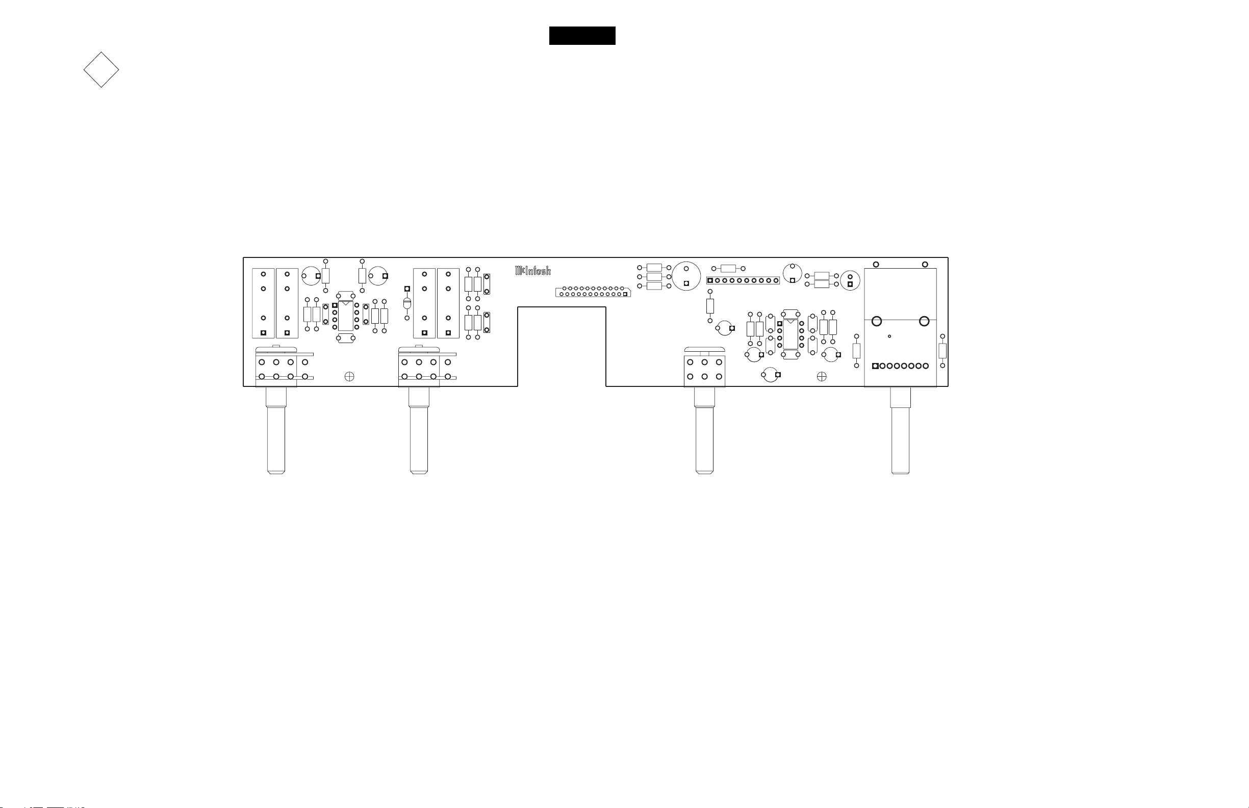
Control Schematic and PCB ............................. 17 - 20
Balanced Schematic and PCB ........................... 21 - 22
Volume/Tone Schematic and PCB ..................... 23 - 26
SERVICE MANUAL
Data Schematic and PCB................................... 27 - 28
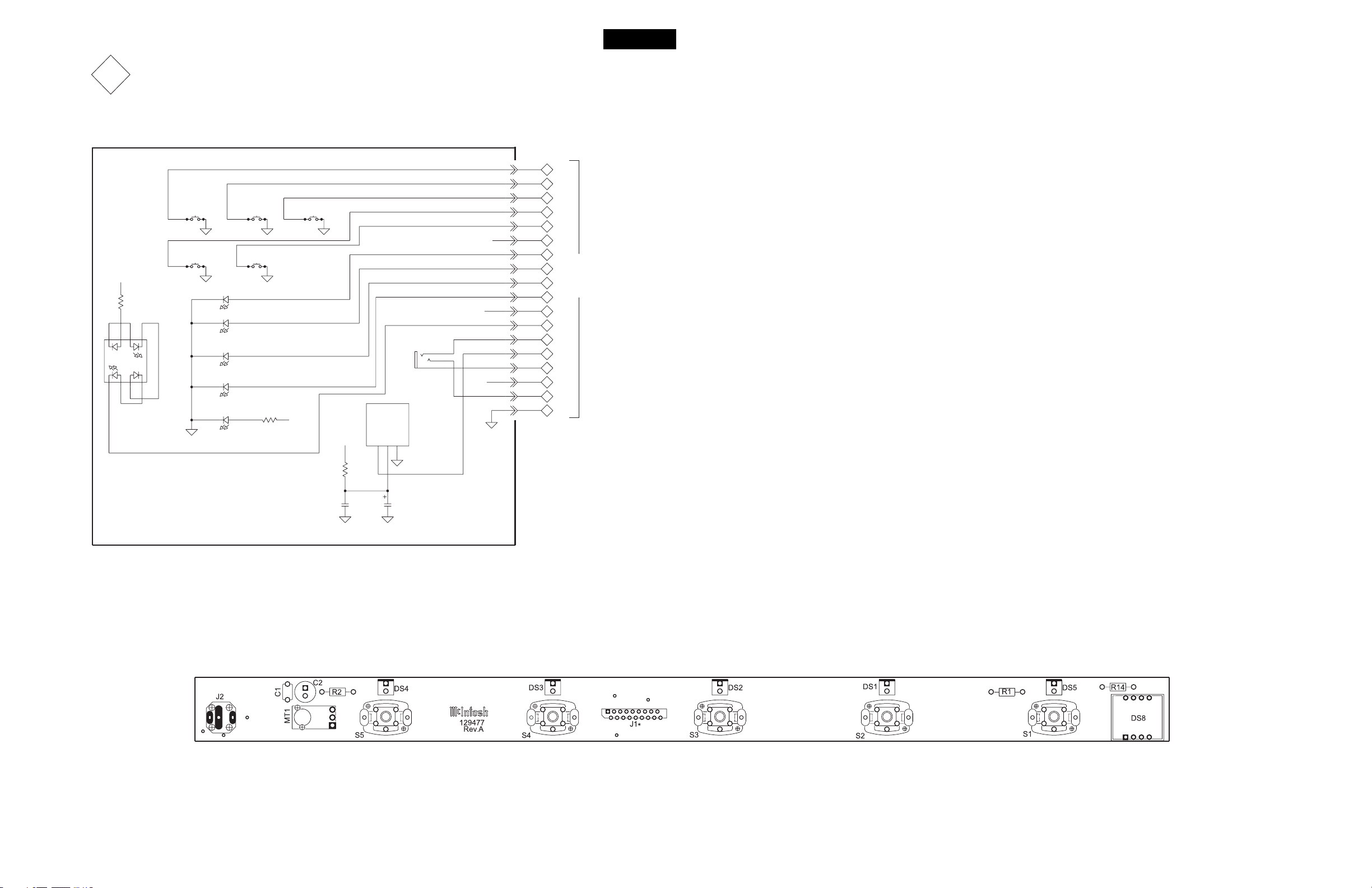
Pushbutton Schematic and PCB ........................ 29 - 30
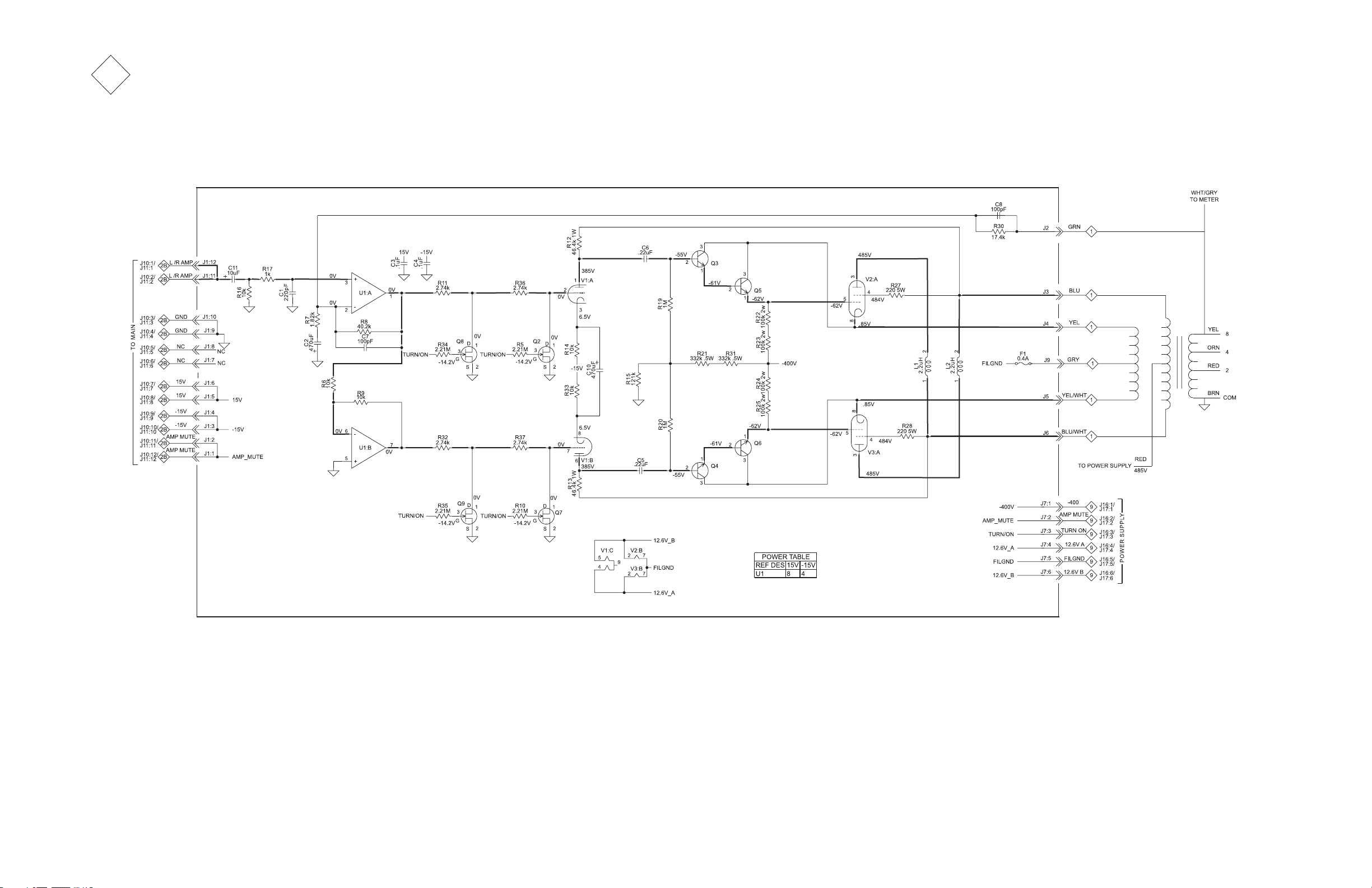
Amplifier Schematic and PCB............................ 31 - 34
Power Supply Schematic and PCB..................... 35 - 38
Meter Schematic and PCB ................................. 39 - 40
Backup PS Schematic and PCB ................................ 41
Terminal Schematic and PCB ................................... 42
Parts List ............................................................ 43 - 48
Exploded View and Parts List ............................. 49 - 52
Repacking Instructions ............................................. 53
Page 2

PERFORMANCE SPECIFICATIONS
Power Output
Minimum sine wave continuous average power output per
channel, both channels operating is:
75 watts into a 2 ohm load
75 watts into a 4 ohm load
75 watts into an 8 ohm load
Rated Power Band
20Hz to 20,000Hz
Total Harmonic Distortion
Maximum Total Harmonic Distortion at any power level
from 250 milliwatts to rated power output is:
0.5% for a 2, 4 or 8 ohm load
Frequency Response
+0, -0.5dB from 20Hz to 20,000Hz
+0, -3dB from 10Hz to 50,000Hz
Sensitivity
Phono: 4.4mV for 2.5V preamp output
High Level: 450mV for 2.5V preamp output
Power Amplifier Input: 2.5V for rated output
A-Weighted Signal To Noise Ratio
Phono Input: 80dB below 10mV input
High Level: 97dB below rated output
Power Amplifier: 110dB below rated output
Intermodulation Distortion
Maximum Intermodulation Distortion if instantaneous
peak output does not exceed twice the rated output, for
any combination of frequencies from 20Hz to 20,000Hz is:
0.5% for a 2, 4 or 8 ohm load
Preamplifier Maximum Voltage Output
Phono: 8V
High Level: 8V
Main Out: 8V at preamp output
Voltage Gain
High Level to Tape output: 0dB
High Level to Preamp output: 15dB
Wide Band Damping Factor
Greater than 18
Power Requirements
100 Volts, 50/60Hz at 3.6 amps
110 Volts, 50/60Hz at 3.6 amps
120 Volts, 50/60Hz at 3.6 amps
220 Volts, 50/60Hz at 1.8 amps
230 Volts, 50/60Hz at 1.8 amps
240 Volts, 50/60Hz at 1.8 amps
Note: Refer to the rear panel of the MA2275 for the correct
voltage.
Preamplifier Tube Compliment
2 - 12AX7A Phono Circuitry
2 - 12AX7A High Level Circuitry
Power Amplifier Tube Compliment
2 - 12AT7
4 - KT88/6550
Overall Dimensions
Width is 17-3/4 inches (45.09cm), Height is 10-1/8 inches
(25.72cm) including feet, Depth is 18-3/4 inches (47.63cm)
including the Front Panel and Knobs
Input Impedance
Phono: 47k ohms, 65pF
High Level: 22k ohms
Maximum Input Signal
Phono: 90mV
High Level: 8V
1. The heavy lines on the schematic denote the primary
signal path.
2. Unless otherwise noted, all voltages indicated on the
schematics are measured under the following conditions:
a. AC input at 120 volts, 50/60Hz.
b. All voltages are +/-10% with respect to ground. A
high impedance (10 megaohm) voltmeter must be used.
3 . Unless otherwise specified:
a. Resistor values are in ohms.
b. Capacitor values are microfarads (uF).
c. Inductor values are in microhenries (uH).
Weight
77 pounds (35 kg) net, 110 pounds (50 kg) in shipping
carton
NO TES
4 . On PC board drawings, Square pad indicates:
a. Polarized Capacitors - Positive
b. Diodes - Cathode
c. Others - Pin 1
5. WARNING
Parts marked with the symbol have critical
characteristics. Use only replacement parts recommended by the manufacturer.
2
Page 3
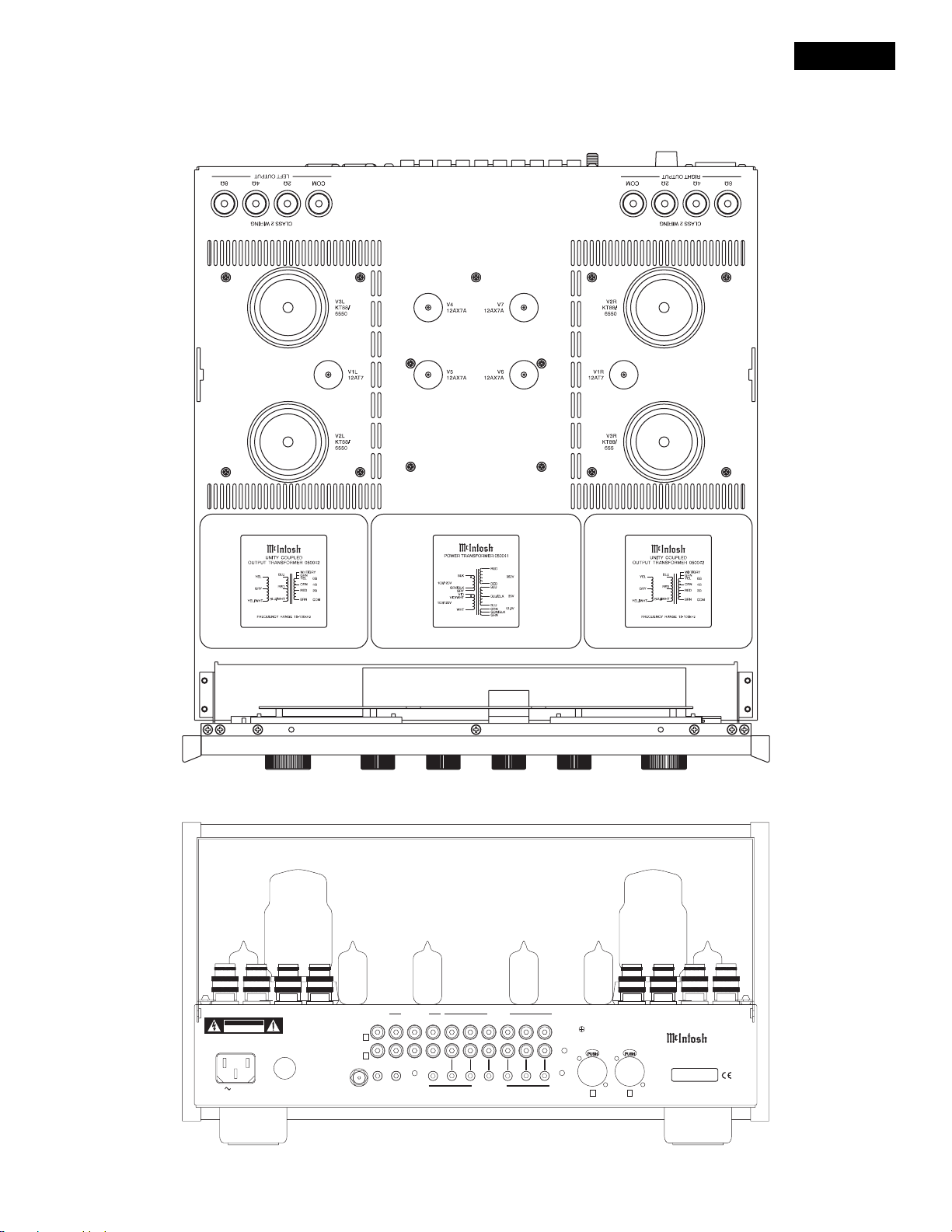
T OP AND REAR VIEWS
MA2275
CAUTION
RISKOF ELECTRIC SHOCK
DONOT OPEN
CAUTION
FORCONTINUED PROTECTION
AGAINSTFIRE HAZARD REPLACE ONLY WITH SAME
TYPEAND RATING FUSE.
120V 50/60Hz 3.6A
AVIS
RISQUEDE CHOC ELECTRIQUE - NE PAS
OUVRIR.REMPLACER PAR UN FUSIBLE DE MEME
TYPE,AMPERAGE ET VOLTAGE.
T 4AL250V
SLO-BLO
EXT SENSOR
POWER
AMP IN
R
L
POWER CONTROL
MAIN
OUTPUTS
PREAMP
12
ACC
INPUTS
DVD
TAPE
TAPE
SUM
TUNER
DATAPORTS
CD 2CD
PHONO
GND
CD INPUT
R
INTEGRATED AMPLIFIER
L
MA2275
McINTOSHLABORATORY, INC.,
BINGHAMTON,NY MADE IN USA
SERIAL
NUMBER
3
Page 4
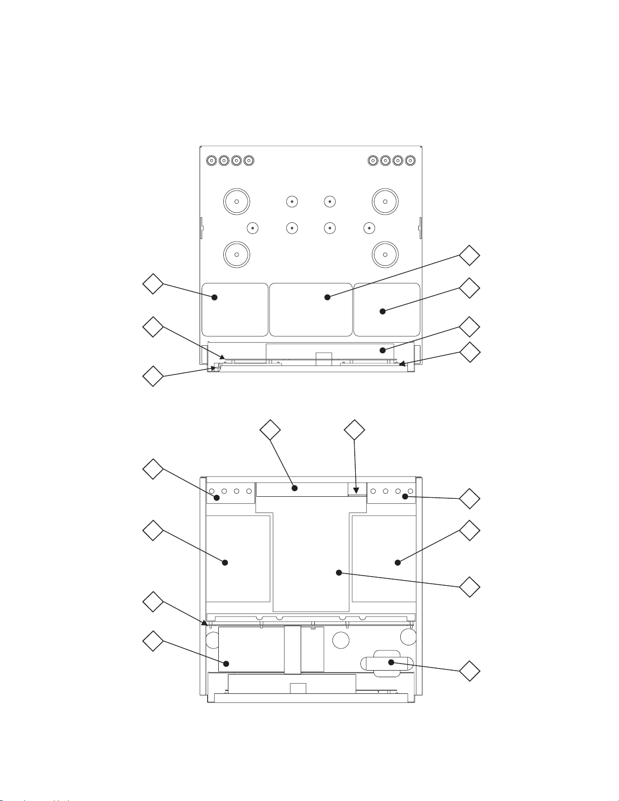
SECTION LOCATIONS
TOP VIEW WITH COVERS REMOVED
POWER
1
TRANSFORMER
OUTPUT
TRANSFORMER
METER
PCB
CONTROL
PCB
TERMINAL
PCB
AMP
PCB
1
3
DATA
PCB
6
BALANCED
PCB
4
12
13
8R 8L
OUTPUT
1
TRANSFORMER
VOLUME/TONE
510
PCB
PUSHBUTTON
7
PCB
TERMINAL
PCB
AMP
PCB
POWER SUPPLY
PCB
BACKUP POWER
SUPPLY PCB
11
MAIN
2
PCB
9
CHOKE
1
FILTER
BOTTOM VIEW WITH COVER REMOVED
4
Page 5
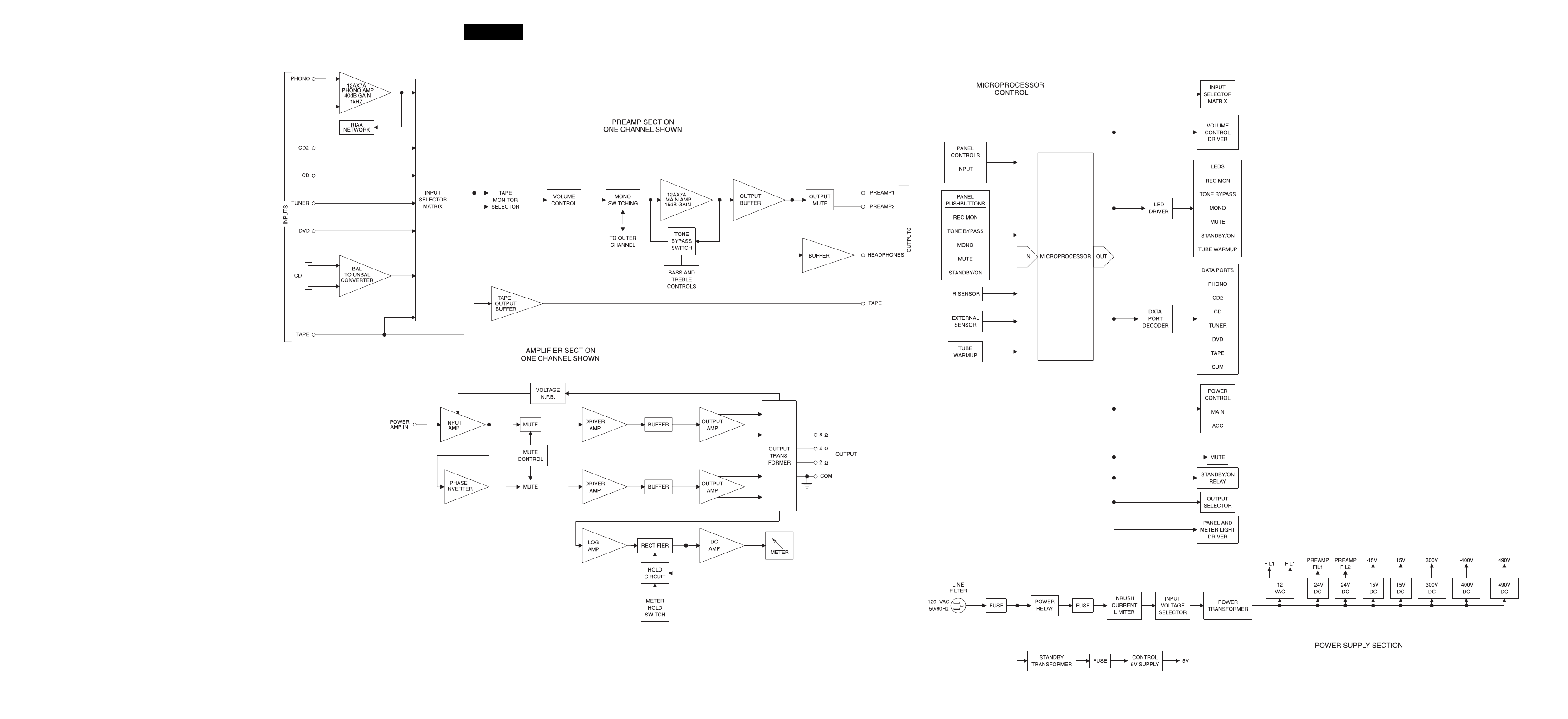
BLOCK DIAGRAM
MA2275
5 76
Page 6
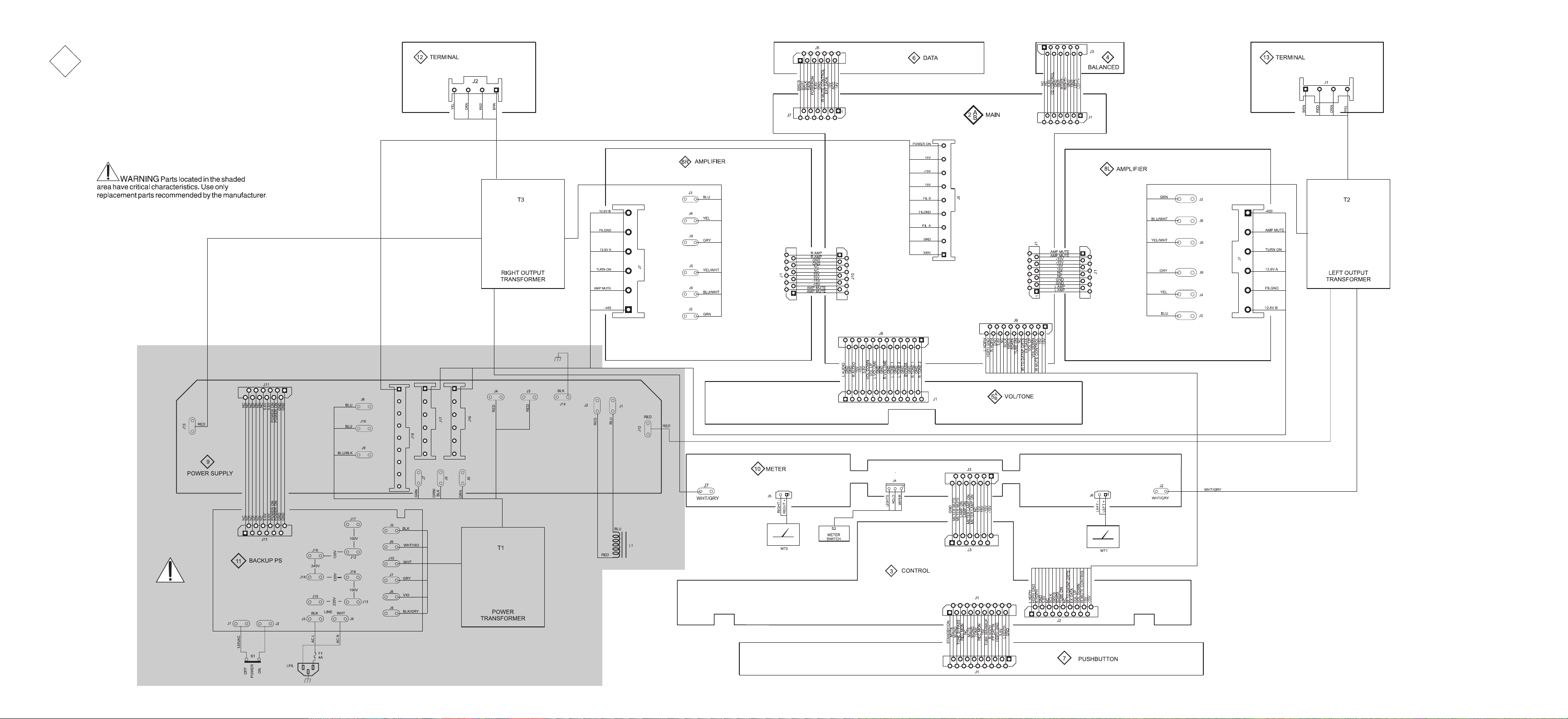
1
INTERCONNECT
8 109
Page 7
MA2275
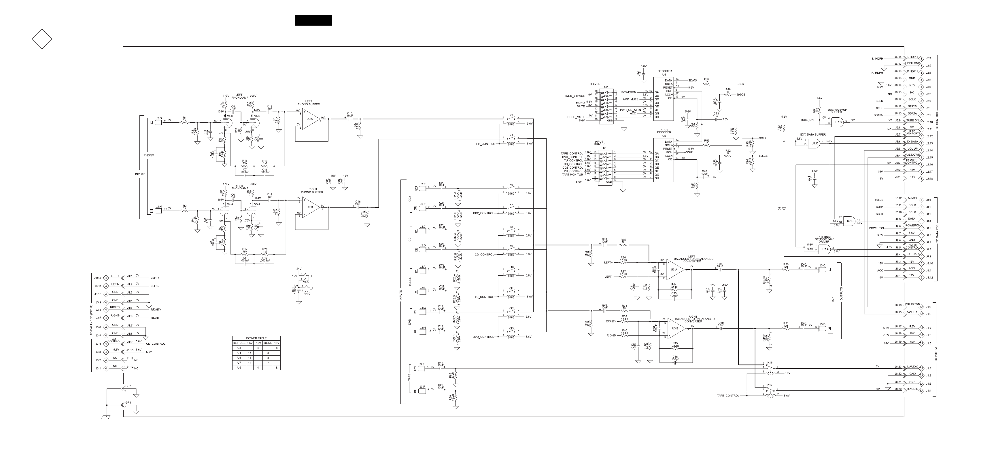
2A
MAIN
049965 SH 1 OF 2
11 1312
Page 8
2B
MAIN
049965 SH 2 OF 2
J6
129472
Rev. A
C13
C9
C86
R47
C44
R48
C77
U10
R43
C75
C60
C59
D1
C42
C73
R74
C85
U9
R21
C84
R15
C14
R22
R18
R17
U4
U2
K21
K1
C10
R16
D4
K20
J8
JMP1
C48C47
R53
R54
C49
R55
R79
R60
R63
R70
R69
C65
K18
C55
C54
C57
C63
U6
R83
C71 C69
R71
C62
R84
J4
C66
J10
R61
C64
K19
R81
Q1
R80
R88
R85
R82
R87
R94
R93
R91
C74
C82
C78
J7
R52
U7
D2
C80
C79
U11
C83
C81
GP2
R57
R58
R27
*
J11
C11
R19
C7
R11
C76
C3
C15
J1
C58
C41
R46
U5
GP1
R95
R23
R92
R86
R96
U1
C43
R5
R6
R25
K2
V5 V6
R13
R4
K3
K7
C5
R9
R2
C24
J2
C2
R31
C6
R10
*
V4
R1
R3
C1
C16
R26R34
C31
R41
R44
R35
C30
K6
K9
R32 R28
C26
C23
R14
R7
R8
R37
R36
C37
C35
C33
K8 K11
C25
C28
R20
R12
C4
U3
C40
C12
C8
J5
40
R
R39
C36
R45
C34
K10
C27
C18
R77
C32
R42
R38
C29
K13 K12
R29
C17
C50
R56
C53
C56
R62
R65R67
R33
C20
J3
R66
C67
C68
R59
C61
R64
U8
R78
R68
C38
C39
R49
K17
C19
C46
R90
R89
C51
K16
*
C52
*
V7
R75
R76
Q4
R73
R72
R24
Q2
R30
Q3
C45
C72 C70
R51
R50
14 1615
CD DVDPH CD2 TUNER TAPE
TAPE OUT 2 AMP INOUT 1
OUT
Page 9
MA2275
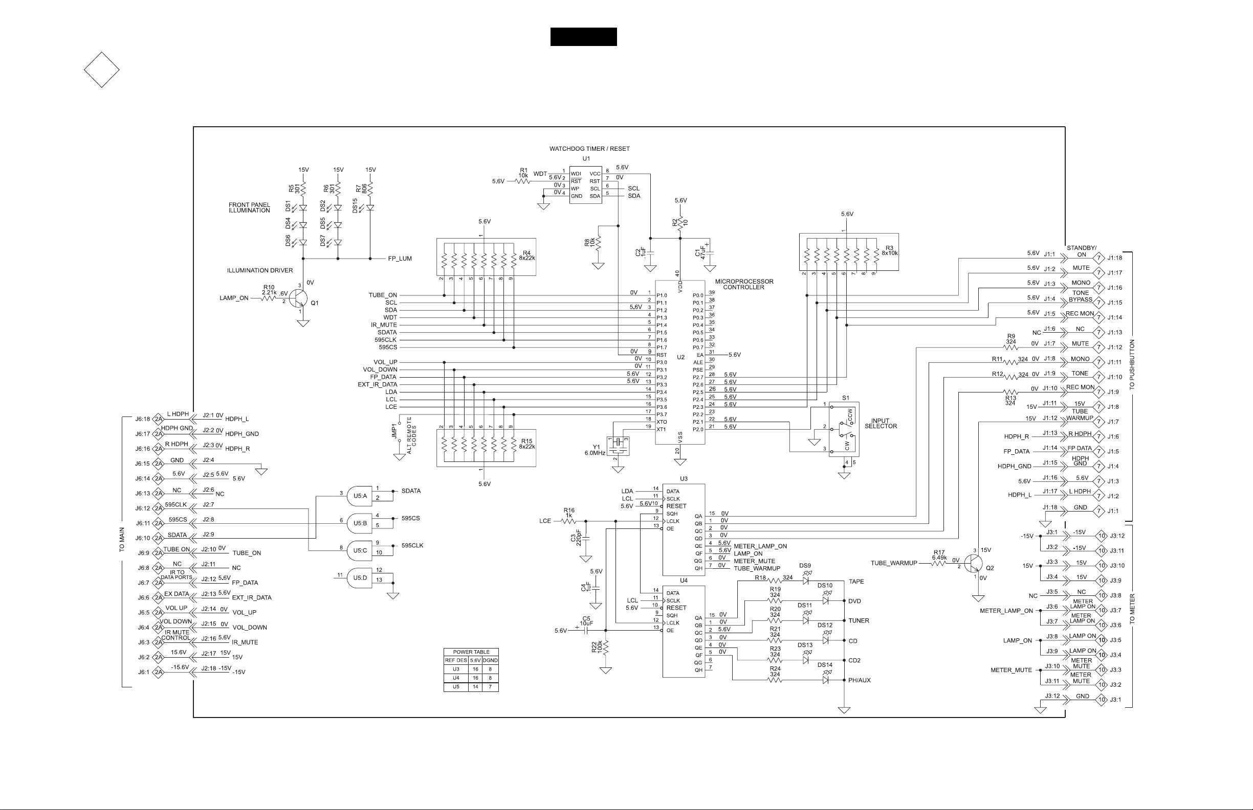
3
CONTROL
049966
17 18
Page 10

3
CONTROL
049966
129473
Rev.A
DS6
Y1
JMP1
DS4
ASSY1
R5
DS1
R15
U2
R4
R1
R3
C1
R17
Q2
J3
U1
C2
R2
R8
U5
DS7
Q1
C5
C4
R18
U4
R19
R20
R21
R23
R24
R11
R9
R12
R13
R10
C3 R22
R16
U3
J2J1
DS11
DS10
DS9
DS5
DS12
S1
DS15
R7
DS13
DS14
R6
DS2
19 20
Page 11

MA2275
4
BALANCED
049967
21 22
Page 12
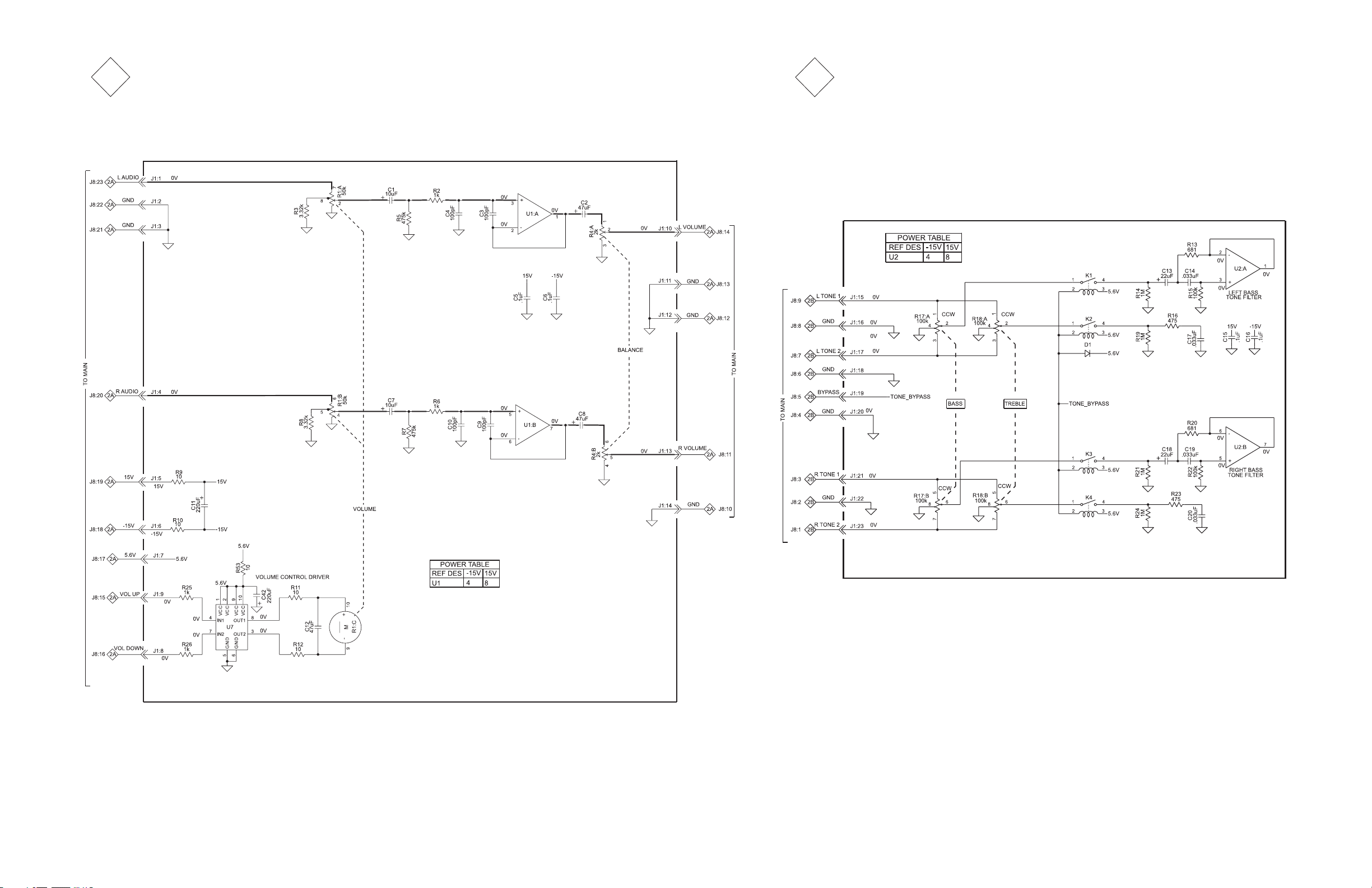
5A
VOLUME/TONE
049968
5B
VOLUME/TONE
049968
23 24
Page 13
MA2275
5
VOLUME/TONE
K3
K1
R17
049968
C13
R14
C16
R13
U2
C14
C15
R15
R21
C19
C18
R22
129475
Rev.A
D1
K4 K2
R20
R18 R4
R19R24
R16R23
C17C20
J1
R53
R10
R9
C11
R25
R26
C2
U7
C1
R5
R2
C8
C3
C4
C42
C5
U1
C6
R11
R12
C9
C10
R6
C7
R7
C12
R8
R3
R1
25 26
Page 14

6
DAT A
049969
SP1
129476
Rev.A
R22
R23 R6
R19
R15
R9 R4 R1 R12
J6
R5
C5
R3
R8 R7
J5 J4 J2 J7 J10
C1
U1
J3 J1 J11
U2
R2 R10 R20
C4
U4
SP2
C3
U3
R21
C2
D3
D2
R13
R14
R11
R18
R17
R16
D1
J8
J9
27 28
Page 15
MA2275
7
1
R14
15V
499
8
DS8
234
PUSHBUTTON
TUBE WARMUP
567
STANDBY/ON
STANDBY/ON
S1 S2 S3
TONE BYPASS
S4
DS1
DS2
DS3
DS4
DS5
REC MON
MUTE
REC MON
S5
MUTE
MONO
TONE BYPASS
R1
324
5V
MONO
049970
IR SENSOR
MT1
5.6V
5.6V
5.6V
5.6V
5.6V
NC
0V
0V
0V
0V
15V
J2
3
2
1
5.6V
5.6V
STANDBY/
J1:18
J1:17
J1:16
J1:15
J1:14
J1:13
J1:12
J1:11
J1:10
0V
0V
J1:9
J1:8
J1:7
J1:6
J1:5
J1:4
J1:3
J1:2
J1:1
ON
MUTE
MONO
TONE
BYPASS
REC MON
NC
MUTE
MONO
TONE
REC MON
15V
TUBE
WARMUP
R HDPH
FP DATA
HDPH
GND
5.6V
L HDPH
GND
3
J1:1
3
J1:2
3
J1:3
3
J1:4
J1:5
3
3
J1:6
3
J1:7
J1:8
J1:9
J1:10
J1:11
J1:12
J1:13
J1:14
J1:15
J1:16
J1:17
J1:18
AY
TO DISPL
3
3
3
3
3
3
3
3
3
3
3
5.6V
R2
C1
100
.1uF
5.6V
C2
Vout
47uF
Vcc
GND
213
5.6V
29 30
Page 16
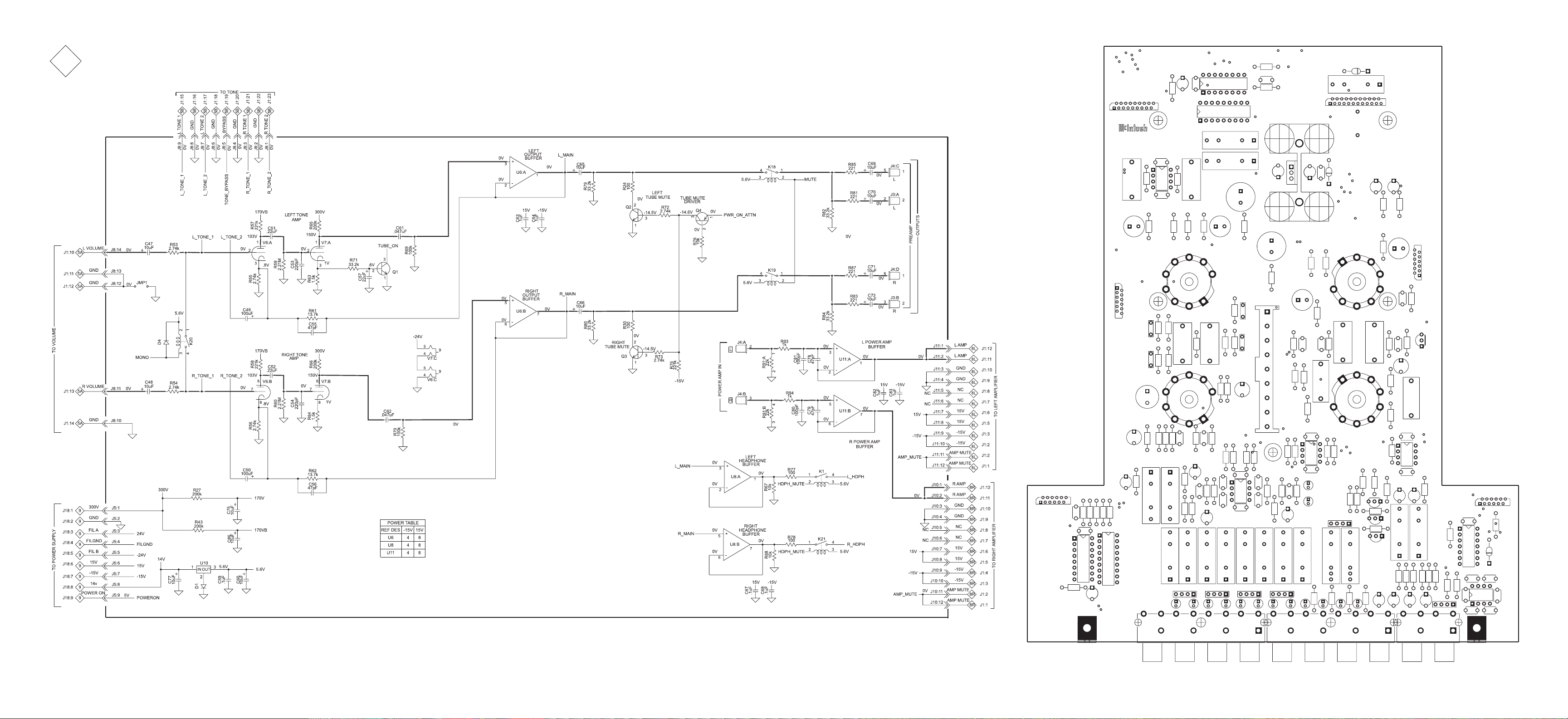
8
R
L
AMPLIFIER
049971
31 32
Page 17

MA2275
8
AMPLIFIER
049971
C11
C3
C7
R9
R6
U1
R7
R8
R11
R36
R34
R5
J1
C1
R17
R16
R32
R37
R10
R35
C2
C10
Q7
Q9
Q8
Q2
R33
R14
C4
Q3
Q5
V3
R25
R24
C8
R30
Q6
Q4
R20
R19
R15
R28
R21
J2
GRN
YEL/WHT
YEL
J6
J5
J7
J9
J4
J3
F1
BLU/WHT
L1
R31
GRY
BLU
V2
R27
C5
R13
V1
L2
R12
C6
R22
R23
129478
Rev.A
33 34
Page 18

9
POWER SUPPLY
049972
T2R
TO POWER TRANSFORMER
J11:1
J11:2
J11:3
J11:4
TO BACKUP PS
J11:5
J11:6
T2L
T1
T1
T1
T1
T1
T1
T1
T1
RED
1
RED J12
1
BLU
1L1
RED
1L1
RED
1
RED
1
GRN
1
GRN/BLK
1
GRN
1
BLU J8
1
BLU/BLK
1
BLU
1
BLK
1
11
11
POWER ON
11
POWER ON
11
GND
11
GND
11
J13
485V
485V
J1
485V
10uF
10uF
R1
18k
47uF
300V REGULATOR
Q1
2
1
D3 D2
R4
2.74M
15V
-15V
D10
R7
300V
1M
AMP_MUTE
POWER AMPLIFIER
C1
D
2
G
S
TURN ON CONTROL
-24V
R8
221k
R9
-15V
TURN/ON
100k
1
Q6
3
R5
100k
3
2
Q2
1
1
Q3
2
3
.47uF
R6
100k
3
C8
1uF
-400V
AMP_MUTE
TURN/ON
FIL_A
FIL_B
-400V
AMP_MUTE
TURN/ON
FIL_A
FIL_B
300V
24V
-24V
15V
-15V
14V
POWERON
J2
490V
J3
C2
J4
J5
J6
J7
J9
J10
J14
J11:6
5V
5V
J11:5
J11:4
J11:3
J11:2
J11:1
.047uF
FIL_A
FIL_B
F1
2A
F2
2A
14V
POWERON
D1
2
34
AC
AC
C13
.047uF
C6
47uF
1
D4
D5
R10
2.2k 2w
D6
D7
D8
D9
C3
C9
C7
680uF
680uF
47uF
C11
C14
-400V
4700uF
4700uF
C4
680uF
C10
680uF
24V
15V REGULATOR
24V
-15V REGULATOR
2
-24V
-24V
75
R
100k 2w
76
R
100k 2w
U2
IN OUT
2
U3
IN OUT
1
R2
100k 2w
C5
15V
31
C12
-15V
3
C15
GP1
J16:1
J16:2
J16:3
J16:4
J16:5
J16:6
J17:1
J17:2
J17:3
J17:4
J17:5
J17:6
J18:1
J18:2
J18:3
J18:4
J18:5
J18:6
J18:7
J18:8
J18:9
1
-400V
AMP MUTE
TURN ON
FIL A
FILGND
FIL B
-400V
AMP MUTE
TURN ON
FIL B
FILGND
FIL B
300V
GND
FIL A
FILGND
FIL B
-15V
POWER ON
15V
14V
8L
J7:1
8L
J7:2
8L
J7:3
8L
J7:4
8L
J7:5
8L
J7:6
8R
J7:1
8R J7:2
8R
J7:3
8R
J7:4
8R J7:5
8R
J7:6
2
J5:1
J5:2
2
J5:3
2
J5:4
2
J5:5
2
J5:6
2
2
J5:7
2
J5:8
2
J5:9
TO L AMP
TO R AMP
TO MAIN
35 36
Page 19

MA2275
9
RED
POWER SUPPLY
U3 U2
F1
D9
J13
C14
C15
C11
D8
049972
RED BLU
J2
R75
R76
J1
C4
C10
C2
RED
J3
D1
C6
D4
J14
C3
C9
D5
129526
D6
J11
C13
D7
C12
R8
F2
R9
Q6
GP1
Q3
R6
R5
R7
Q2
C8
D10
R4
BLU BLUBLU/BLK
J8
J10
J9
J18
GRN
J17
J5
GRN/BLK
GRN
J6
Rev.A
J16
C7
J7
RED BLK
J4
R10
C5
D3
Q1
R1
RED
J12
R2
D2
37 38
Page 20
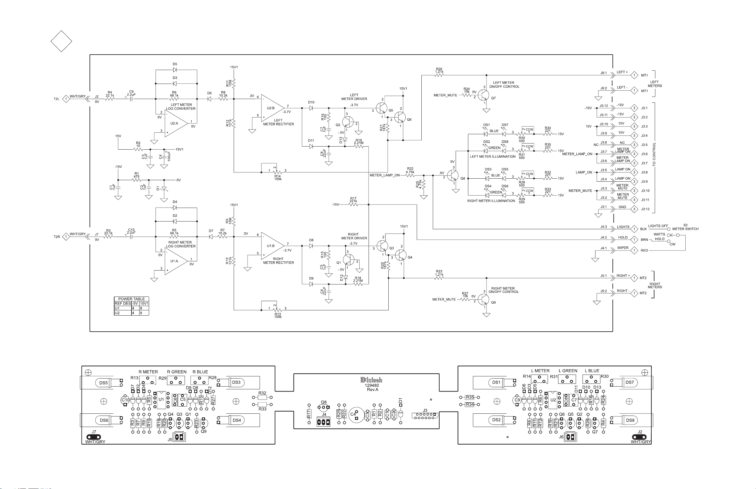
10
METER
049973
39 40
Page 21
MA2275
11
BACKUP PS
050007
12
TERMINAL
050052
13
TERMINAL
050052
41 42
Page 22

PARTS LIST
Ref. No. Description Part No.
INTERCONNECT
1
L1 CHOKE FILTER .5H 122379
LFIL LINE FILTER 117755
MT 1 METER 124087
MT 2 METER 124087
S1 POWER SWITCH 171026
S2 SWITCH 146243
T1 POTTED TRANSFORMER, POWER 050041
T2 POTTED TRANSFORMER, OUTPUT 050042
T3 POTTED TRANSFORMER, OUTPUT 050042
049965 MAIN PCB
2
C1 CAP MONO 47PF 200V 10% NPO 061299
C2 CAP MONO 47PF 200V 10% NPO 061299
C3 CAP ELECT 100UF 16V OR 25V 066447
C4 CAP ELECT 100UF 16V OR 25V 066447
C5 CAP MPF 0.1UF 630VDC 064431
C6 CAP MPF 0.1UF 630VDC 064431
C7 CAP PF 0.001UF 5% 63VDC 064300
C8 CAP PF 0.001UF 5% 63VDC 064300
C9 CAP ELECT 100UF 25V-50V 066161
C10 CAP ELECT 100UF 25V-50V 066161
C11 CAP MPF 0.0033UF 5% 63VDC 064306
C12 CAP MPF 0.0033UF 5% 63VDC 064306
C13 CAP MPF 0.1UF 630VDC 064431
C14 CAP MPF 0.1UF 630VDC 064431
C15 CAP ELECT 10UF 50V 066445
C16 CAP ELECT 10UF 50V 066445
C17 CAP ELECT 10UF 16V 4X5 CASE 066382
C18 CAP ELECT 10UF 16V 4X5 CASE 066382
C19 CAP ELECT 10UF 16V 4X5 CASE 066382
C20 CAP ELECT 10UF 16V 4X5 CASE 066382
C23 CAP ELECT 10UF 16V 4X5 CASE 066382
C24 CAP ELECT 10UF 16V 4X5 CASE 066382
C25 CAP ELECT 10UF 16V 4X5 CASE 066382
C26 CAP ELECT 10UF 16V 4X5 CASE 066382
C27 CAP ELECT 10UF 16V 4X5 CASE 066382
C28 CAP ELECT 10UF 16V 4X5 CASE 066382
C29 CAP ELECT 10UF 50V 066445
C30 CAP ELECT 10UF 50V 066445
C31 CAP MONO 100PF 100V 10% NPO 061300
C32 CAP MONO 100PF 100V 10% NPO 061300
C33 CAP MONO 100PF 100V 10% NPO 061300
C34 CAP MONO 100PF 100V 10% NPO 061300
C35 CAP MONO 100PF 100V 10% NPO 061300
C36 CAP MONO 100PF 100V 10% NPO 061300
C37 CAP MONO .1uF 50V 20% Z5U 061305
C38 CAP ELECT 10UF 16V 4X5 CASE 066382
C39 CAP ELECT 10UF 16V 4X5 CASE 066382
C40 CAP MONO .1uF 50V 20% Z5U 061305
C41 CAP MONO .1uF 50V 20% Z5U 061305
C42 CAP MONO .1uF 50V 20% Z5U 061305
C43 CAP ELECT 10UF 50V 066445
C44 CAP MONO 220PF 100V 10% NPO 061301
C45 CAP ELECT 10UF 16V 4X5 CASE 066382
C46 CAP ELECT 10UF 16V 4X5 CASE 066382
C47 CAP ELECT 10UF 50V 066445
C48 CAP ELECT 10UF 50V 066445
C49 CAP ELECT 100UF 25V-50V 066161
C50 CAP ELECT 100UF 25V-50V 066161
C51 CAP MPF 0.22UF 400VDC 064438
C52 CAP MPF 0.22UF 400VDC 064438
C53 CAP MONO 220PF 100V 10% NPO 061301
C54 CAP MONO 220PF 100V 10% NPO 061301
C55 CAP MONO 47PF 200V 10% NPO 061299
C56 CAP MONO 47PF 200V 10% NPO 061299
C57 CAP ELECT 22UF 100V 066506
C58 CAP MONO 220PF 100V 10% NPO 061301
C59 CAP MONO .1uF 50V 20% Z5U 061305
C60 CAP ELECT 10UF 50V 066445
C61 CAP POLY .047UF 10% 1000VDC 064434
C62 CAP POLY .047UF 10% 1000VDC 064434
C63 CAP MONO .1uF 50V 20% Z5U 061305
C64 CAP MONO .1uF 50V 20% Z5U 061305
C65 CAP ELECT 10UF 50V 066445
C66 CAP ELECT 10UF 50V 066445
C67 CAP MONO .1uF 50V 20% Z5U 061305
C68 CAP MONO .1uF 50V 20% Z5U 061305
C69 CAP ELECT 10uF 50V 066445
C70 CAP ELECT 10uF 50V 066445
C71 CAP ELECT 10uF 50V 066445
C72 CAP ELECT 10uF 50V 066445
C73 CAP ELECT 10UF 50V 066445
C74 CAP MONO .1uF 50V 20% Z5U 061305
C75 CAP ELECT 10UF 250V 066493
C76 CAP ELECT 1000UF 25V 066513
C77 CAP ELECT 10UF 50V 066445
C78 CAP MONO 47PF 200V 10% NPO 061299
C79 CAP MONO 47PF 200V 10% NPO 061299
C80 CAP MONO 100PF 100V 10% NPO 061300
C81 CAP MONO 100PF 100V 10% NPO 061300
C82 CAP MONO .1uF 50V 20% Z5U 061305
C83 CAP MONO .1uF 50V 20% Z5U 061305
C84 CAP MONO .1uF 50V 20% Z5U 061305
C85 CAP MONO .1uF 50V 20% Z5U 061305
C86 CAP ELECT 10UF 250V 066493
D1 DIODE SILICON 070047
D2 DIODE SILICON 070047
D4 DIODE SILICON 070047
GP1 BRACKET PCB CARD MOUNTING 003611
GP2 BRACKET PCB CARD MOUNTING 003611
J1 CONN 12 PIN FFC 117720
J2 JACK RCA 4X2 WHT/RED 14MM 117791
J3 JACK RCA 4X2 WHT/RED 14MM 117791
J4 JACK RCA 2X2 WHT/RED 14MM 117789
J5 HEADER 9 CIRCUIT POST NATURAL 117724
J6 CONN FFC 18PIN 117765
J7 CONN 12 PIN FFC 117720
J8 CONN 23 PIN FFC 117715
J10 CONN 12 PIN FFC 117720
J11 CONN 12 PIN FFC 117720
K1 RELAY REED FORM 1A 5V 500 OHMS 087050
K2 RELAY REED FORM 1A 5V 500 OHMS 087050
K3 RELAY REED FORM 1A 5V 500 OHMS 087050
K6 RELAY REED FORM 1A 5V 500 OHMS 087050
K7 RELAY REED FORM 1A 5V 500 OHMS 087050
K8 RELAY REED FORM 1A 5V 500 OHMS 087050
K9 RELAY REED FORM 1A 5V 500 OHMS 087050
K10 RELAY REED FORM 1A 5V 500 OHMS 087050
K11 RELAY REED FORM 1A 5V 500 OHMS 087050
K12 RELAY REED FORM 1A 5V 500 OHMS 087050
K13 RELAY REED FORM 1A 5V 500 OHMS 087050
K16 RELAY REED FORM 1C 5V 125 OHM 087056
K17 RELAY REED FORM 1C 5V 125 OHM 087056
K18 RELAY REED FORM 1A 5V 500 OHMS 087050
K19 RELAY REED FORM 1A 5V 500 OHMS 087050
K20 RELAY REED FORM 1A 5V 500 OHMS 087050
K21 RELAY REED FORM 1A 5V 500 OHMS 087050
Q1 TRANSISTOR NPN 132223
Q2 TRANSISTOR NPN 132257
Q3 TRANSISTOR NPN 132257
Q4 TRANSISTOR PNP 132224
R1 RES MF 1K 1% 1/4W 144090
R2 RES MF 1K 1% 1/4W 144090
R3 RES MF 47.5K 1% 1/4W 144108
R4 RES MF 47.5K 1% 1/4W 144108
R5 RES MF 953 OHM 1/4W 1% 144473
R6 RES MF 1.74K 1% 1/4W 144351
R7 RES MF 953 OHM 1/4W 1% 144473
R8 RES MF 1.74K 1% 1/4W 144351
R9 RES MF 221K 1% 1/4W 144421
R10 RES MF 221K 1% 1/4W 144421
R11 RES MF 75K 1% 1/4W 144156
R12 RES MF 75K 1% 1/4W 144156
R13 RES MF 1M 1/4W 144269
R14 RES MF 1M 1/4W 144269
R15 RES MF 681 OHM 1% 1/4W 144195
R16 RES MF 681 OHM 1% 1/4W 144195
R17 RES MF 150K 1% 1/4W 144419
R18 RES MF 150K 1% 1/4W 144419
R19 RES MF 1M 1/4W 144269
R20 RES MF 1M 1/4W 144269
R21 RES MF 221K 1% 1/4W 144421
R22 RES MF 221K 1% 1/4W 144421
R23 RES MF 2.21K 1% 1/4W 144298
R24 RES MF 100 OHM 1% 1/4W 144196
R25 RES MF 22.1K 1% 1/4W 144187
R26 RES MF 22.1K 1% 1/4W 144187
R27 RES MF 200K 1% 1/4W 144117
R28 RES NETWORK 2X220K ISO 144262
R29 RES NETWORK 2X220K ISO 144262
R30 RES MF 100 OHM 1% 1/4W 144196
R31 RES NETWORK 2X220K ISO 144262
R32 RES NETWORK 2X220K ISO 144262
R33 RES MF 221K 1% 1/4W 144421
R34 RES MF 221K 1% 1/4W 144421
R35 RES MF 1K 1% 1/4W 144090
R36 RES MF 47.5K 1% 1/4W 144108
R37 RES MF 47.5K 1% 1/4W 144108
R38 RES MF 1K 1% 1/4W 144090
R39 RES MF 47.5K 1% 1/4W 144108
R40 RES MF 47.5K 1% 1/4W 144108
R41 RES MF 24.9K 1% 1/4W 144439
R42 RES MF 24.9K 1% 1/4W 144439
R43 RES MF 200K 1% 1/4W 144117
R44 RES MF 22.1K 1% 1/4W 144187
R45 RES MF 22.1K 1% 1/4W 144187
R46 RES MF 100K 1% 1/4W 144113
R47 RES MF 1K 1% 1/4W 144090
R48 RES MF 1K 1% 1/4W 144090
R49 RES NETWORK 2X220K ISO 144262
R50 RES MF 221 OHM 1% 1/4W 144172
R51 RES MF 221 OHM 1% 1/4W 144172
R52 RES MF 100K 1% 1/4W 144113
R53 RES MF 2.74K 1% 1/4W 144304
R54 RES MF 2.74K 1% 1/4W 144304
R55 RES MF 2.74K 1% 1/4W 144304
R56 RES MF 2.74K 1% 1/4W 144304
R57 RES MF 221K 1% 1/4W 144421
R58 RES MF 221K 1% 1/4W 144421
R59 RES MF 2.21M 1/4W 144265
R60 RES MF 2.21M 1/4W 144265
R61 RES MF 13.7K 1% 1/4W 144342
R62 RES MF 13.7K 1% 1/4W 144342
R63 RES MF 1.5K 1% 1/4W 144128
R64 RES MF 1.5K 1% 1/4W 144128
R65 RES MF 200K 1% 1/4W 144117
R66 RES MF 200K 1% 1/4W 144117
R67 RES MF 10K 1% 1/4W 144053
R68 RES MF 10K 1% 1/4W 144053
R69 RES MF 100K 1% 1/4W 144113
R70 RES MF 100K 1% 1/4W 144113
R71 RES MF 33.2K 1% 1/4W 144015
R72 RES MF 2.74K 1% 1/4W 144304
R73 RES MF 2.74K 1% 1/4W 144304
R74 RES MF 100K 1% 1/4W 144113
R75 RES MF 221K 1% 1/4W 144421
R76 RES MF 10K 1% 1/4W 144053
R77 RES MF 100 OHM 1% 1/4W 144196
R78 RES MF 100 OHM 1% 1/4W 144196
R79 RES MF 33.2K 1% 1/4W 144015
R80 RES MF 33.2K 1% 1/4W 144015
R81 RES MF 221 OHM 1% 1/4W 144172
R82 RES MF 33.2K 1% 1/4W 144015
R83 RES MF 221 OHM 1% 1/4W 144172
R84 RES MF 33.2K 1% 1/4W 144015
R85 RES MF 221 OHM 1% 1/4W 144172
R86 RES MF 1K 1% 1/4W 144090
R87 RES MF 221 OHM 1% 1/4W 144172
R88 RES MF 10K 1% 1/4W 144053
R89 RES MF 40.2K 1% 1/4W 144107
R90 RES MF 40.2K 1% 1/4W 144107
R91 RES MF 4.75 MEG 1% 1/2W 144366
R92 RES MF 1K 1% 1/4W 144090
R93 RES MF 1K 1% 1/4W 144090
R94 RES MF 1K 1% 1/4W 144090
R95 RES MF 2.21K 1% 1/4W 144298
R96 RES MF 2.21K 1% 1/4W 144298
U1 IC OCTAL DARLNGTON TRANS ARRAY 133258
U2 IC OCTAL DARLNGTON TRANS ARRAY 133258
U3 IC DUAL OPERATIONAL AMPLIFIER 133260
U4 IC SHFT REG SER-PAR 133186
U5 IC SHFT REG SER-PAR 133186
U6 IC DUAL OPERATIONAL AMPLIFIER 133260
U7 IC AND 2 INPUT X 4 133175
U8 IC DUAL OPERATIONAL AMPLIFIER 133260
U9 IC DUAL OPERATIONAL AMPLIFIER 133260
U10 IC REGULATOR +5V 133108
U11 IC DUAL OPERA TIONAL AMPLIFIER 133260
V4 TUBE 12AX7A MCINTOSH 165065
V5 TUBE 12AX7A MCINTOSH 165065
V6 TUBE 12AX7A MCINTOSH 165065
V7 TUBE 12AX7A MCINTOSH 165065
3
049966 CONTROL PCB
C1 CAP ELECT 47UF 35V 066446
C2 CAP MONO .1uF 50V 20% Z5U 061305
C3 CAP MONO 220PF 100V 10% NPO 061301
C4 CAP MONO .1uF 50V 20% Z5U 061305
C5 CAP ELECT 10UF 50V 066445
DS1 LED GREEN 5MM HI-INTENSITY 058165
DS2 LED GREEN 5MM HI-INTENSITY 058165
4443
Page 23

PARTS LIST con’t
MA2275
DS4 LED GREEN 5MM HI-INTENSITY 058165
DS5 LED GREEN 5MM HI-INTENSITY 058165
DS6 LED GREEN 5MM HI-INTENSITY 058165
DS7 LED GREEN 5MM HI-INTENSITY 058165
DS9 LED SQUARE RED 058109
DS10 LED SQUARE RED 058109
DS11 LED SQUARE RED 058109
DS12 LED SQUARE RED 058109
DS13 LED SQUARE RED 058109
DS14 LED SQUARE RED 058109
DS15 LED GREEN 5MM HI-INTENSITY 058165
J1 CONN FFC 18PIN 117765
J2 CONN FFC 18PIN 117765
J3 CONN 12 PIN FFC 117720
Q1 TRANSISTOR NPN SILICON 132171
Q2 TRANSISTOR NPN 132223
R1 RES MF 10K 1% 1/4W 144053
R2 RES MF 10 OHM 1% 1/4W 144157
R3 RES NET 10K X8 RES B 144253
R4 RES NETWORK 9X-1-223 144238
R5 RES MF 301 OHM 1% 1/4W 144484
R6 RES MF 301 OHM 1% 1/4W 144484
R7 RES MF 806 OHM 1% 1/4W 144089
R8 RES MF 10K 1% 1/4W 144053
R9 RES MF 324 OHM 1% 1/4W 144338
R10 RES MF 2.21K 1% 1/4W 144298
R11 RES MF 324 OHM 1% 1/4W 144338
R12 RES MF 324 OHM 1% 1/4W 144338
R13 RES MF 324 OHM 1% 1/4W 144338
R15 RES NETWORK 9X-1-223 144238
R16 RES MF 1K 1% 1/4W 144090
R17 RES MF 6.49K 1% 1/4W 144140
R18 RES MF 240 OHM 1% 1/4W 144338
R19 RES MF 240 OHM 1% 1/4W 144338
R20 RES MF 240 OHM 1% 1/4W 144338
R21 RES MF 240 OHM 1% 1/4W 144338
R22 RES MF 100K 1% 1/4W 144113
R23 RES MF 240 OHM 1% 1/4W 144338
R24 RES MF 240 OHM 1% 1/4W 144338
S1 PC BD SWITCH 129294
U1 IC SUPERVISOR WITH EEPROM 133468
U2 IC PROGRAMMED MC2275 V1.00 133523
U3 IC SHFT REG SER-PAR 133186
U4 IC SHFT REG SER-PAR 133186
U5 IC AND 2 INPUT X 4 133175
Y1 RESONATOR CERAMIC 6.0MHZ W/CAP 180039
4
049967 BALANCED PCB
C1 CAP ELECT 10UF 50V 066445
C2 CAP ELECT 10UF 50V 066445
C3 CAP ELECT 10UF 50V 066445
C4 CAP ELECT 10UF 50V 066445
C5 CAP ELECT 10UF 50V 066445
C6 CAP ELECT 10UF 50V 066445
C7 CAP ELECT 10UF 50V 066445
C8 CAP ELECT 10UF 50V 066445
D1 DIODE SILICON 070047
J1 XLR FEMALE VER TICAL WITH LATCH 117813
J2 XLR FEMALE VER TICAL WITH LATCH 117813
J3 CONN 12 PIN FFC 117720
K1 RELAY REED FORM 1A 5V 500 OHMS 087050
K2 RELAY REED FORM 1A 5V 500 OHMS 087050
K3 RELAY REED FORM 1A 5V 500 OHMS 087050
K4 RELAY REED FORM 1A 5V 500 OHMS 087050
R1 RES NETWORK 2X220K ISO 144262
R2 RES NETWORK 2X220K ISO 144262
R3 RES NETWORK 2X220K ISO 144262
R4 RES NETWORK 2X220K ISO 144262
5
049968 VOLUME/TONE PCB
C1 CAP ELECT 10UF 50V 066445
C2 CAP ELECT 47UF 35V 066446
C3 CAP MONO 100PF 100V 10% NPO 061300
C4 CAP MONO 100PF 100V 10% NPO 061300
C5 CAP MONO .1uF 50V 20% Z5U 061305
C6 CAP MONO .1uF 50V 20% Z5U 061305
C7 CAP ELECT 10UF 50V 066445
C8 CAP ELECT 47UF 35V 066446
C9 CAP MONO 100PF 100V 10% NPO 061300
C10 CAP MONO 100PF 100V 10% NPO 061300
C11 CAP ELECT 220UF 50V 20% 066254
C12 CAP ELECT 47UF 10V BP 066378
C13 CAP ELECT 22UF 100V 066506
C14 CAP MPF 0.033UF 5% 63VDC 064318
C15 CAP MONO .1uF 50V 20% Z5U 061305
C16 CAP MONO .1uF 50V 20% Z5U 061305
C17 CAP MPF 0.033UF 5% 63VDC 064318
C18 CAP ELECT 22UF 100V 066506
C19 CAP MPF 0.033UF 5% 63VDC 064318
C20 CAP MPF 0.033UF 5% 63VDC 064318
C42 CAP ELECT 220UF 25V 066507
D1 DIODE SILICON 070047
J1 CONN 23 PIN FFC 117715
K1 RELAY REED FORM 1A 5V 500 OHMS 087050
K2 RELAY REED FORM 1A 5V 500 OHMS 087050
K3 RELAY REED FORM 1A 5V 500 OHMS 087050
K4 RELAY REED FORM 1A 5V 500 OHMS 087050
R1 POT 50KAX2 134490
R2 RES MF 1K 1% 1/4W 144090
R3 RES MF 3.32K 1% 1/4W 144095
R4 POT BALANCE 2KOHM 134464
R5 RES MF 475K 1% 1/4W 144364
R6 RES MF 1K 1% 1/4W 144090
R7 RES MF 475K 1% 1/4W 144364
R8 RES MF 3.32K 1% 1/4W 144095
R9 RES MF 10 OHM 1% 1/4W 144157
R10 RES MF 10 OHM 1% 1/4W 144157
R11 RES MF 10 OHM 1% 1/4W 144157
R12 RES MF 10 OHM 1% 1/4W 144157
R13 RES MF 681 OHM 1% 1/4W 144195
R14 RES MF 1M 1/4W 144269
R15 RES MF 100K 1% 1/4W 144113
R16 RES MF 475 OHM 1% 1/4W 144086
R17 POTENTIOMETER 134457
R18 POTENTIOMETER 134457
R19 RES MF 1M 1/4W 144269
R20 RES MF 681 OHM 1% 1/4W 144195
R21 RES MF 1M 1/4W 144269
R22 RES MF 100K 1% 1/4W 144113
R23 RES MF 475 OHM 1% 1/4W 144086
R24 RES MF 1M 1/4W 144269
R25 RES MF 1K 1% 1/4W 144090
R26 RES MF 1K 1% 1/4W 144090
R53 RES MF 10 OHM 1% 1/4W 144157
U1 IC DUAL OPERATIONAL AMPLIFIER 133260
U2 IC OPAMP NE4558N 133028
U7 IC DC MOTOR DRIVER 133191
6
049969 DA T A PCB
C1 CAP MONO .1uF 50V 20% Z5U 061305
C2 CAP MONO 1000PF 50V 10% NPO 061303
C3 CAP MONO .1uF 50V 20% Z5U 061305
C4 CAP MONO .1uF 50V 20% Z5U 061305
C5 CAP MONO 220PF 100V 10% NPO 061301
D1 DIODE SILICON 070047
D2 DIODE SILICON 070047
D3 DIODE SILICON 070047
J1 JACK HEADPHONE STEREO 1/8IN 117759
J2 JACK HEADPHONE STEREO 1/8IN 117759
J3 JACK HEADPHONE STEREO 1/8IN 117759
J4 JACK HEADPHONE STEREO 1/8IN 117759
J5 JACK HEADPHONE STEREO 1/8IN 117759
J6 JACK HEADPHONE STEREO 1/8IN 117759
J7 JACK HEADPHONE STEREO 1/8IN 117759
J8 CONN 12 PIN FFC 117720
J9 CONN GOLD F RIGHT ANGLE 117661
J10 JACK HEADPHONE STEREO 1/8IN 117759
J11 JACK HEADPHONE STEREO 1/8IN 117759
R1 RES MF 100 OHM 1% 1/4W 144196
R2 RES MF 100 OHM 1% 1/4W 144196
R3 RES MF 1K 1% 1/4W 144090
R4 RES MF 100 OHM 1% 1/4W 144196
R5 RES MF 1K 1% 1/4W 144090
R6 RES MF 1K 1% 1/4W 144090
R7 RES MF 100 OHM 1% 1/4W 144196
R8 RES MF 100 OHM 1% 1/4W 144196
R9 RES MF 100 OHM 1% 1/4W 144196
R10 RES MF 100 OHM 1% 1/4W 144196
R11 RES MF 1K 1% 1/4W 144090
R12 RES MF 10 OHM 1% 1/4W 144157
R13 RES MF 221 OHM 1% 1/4W 144172
R14 RES MF 61.9K OHM 1/4W 144335
R15 RES MF 10 OHM 1% 1/4W 144157
R16 RES MF 22.1K 1% 1/4W 144187
R17 RES MF 182 OHM 1/4W 1% 144273
R18 RES MF 182 OHM 1/4W 1% 144273
R19 RES MF 2.21K 1% 1/4W 144298
R20 RES MF 182 OHM 1/4W 1% 144273
R21 RES MF 182 OHM 1/4W 1% 144273
R22 RES MF 2.21K 1% 1/4W 144298
R23 RES MF 2.21K 1% 1/4W 144298
SP1 BRACKET PCB CARD MOUNTING 003611
SP2 BRACKET PCB CARD MOUNTING 003611
U1 IC SHFT REG SER-PAR 133186
U2 IC 8 LN DRIVER ARRAY 133180
U3 IC OPERATIONAL AMPLIFIER 133189
U4 IC AND 2 INPUT X 4 133175
7
049970 PUSHBUTTON PCB
C1 CAP MONO .1uF 50V 20% Z5U 061305
C2 CAP ELECT 47UF 16V 6.3X5 CASE 066380
DS1 LED SQUARE RED 058109
DS2 LED SQUARE RED 058109
DS3 LED SQUARE RED 058109
DS4 LED SQUARE RED 058109
DS5 LED SQUARE RED 058109
DS8 LED ARRA Y(4) YELLOW SQUARE 058126
J1 CONN FFC 18PIN 117765
J2 JACK PHONO 1/8 STEREO VER 117462
M T1 SENSOR IR 38KHZ 121046
R1 RES MF 324 OHM 1% 1/4W 144338
R2 RES MF 100 OHM 1% 1/4W 144196
R14 RES MF 499 1% 1/4W 144087
S1 SWITCH PB TACT 150058
S2 SWITCH PB TACT 150058
S3 SWITCH PB TACT 150058
S4 SWITCH PB TACT 150058
S5 SWITCH PB TACT 150058
8
049971 AMPLIFIER PCB
C1 CAP MONO 220PF 100V 10% NPO 061301
C2 CAP ELECT 470UF 16V 066508
C3 CAP MONO .1uF 50V 20% Z5U 061305
C4 CAP MONO .1uF 50V 20% Z5U 061305
C5 CAP POLYPROP 0.22UF 20% 1KVDC 064432
C6 CAP POLYPROP 0.22UF 20% 1KVDC 064432
C7 CAP MONO 100PF 100V 10% NPO 061300
C8 CAP MONO 100PF 100V 10% NPO 061300
C10 CAP ELECT 470UF 16V 066508
C11 CAP ELECT 10UF 50V 066445
F1 FUSE T 0.4A 250V 089108
J1 CONN 12 PIN FFC 117720
J2 BLADE F AST ON W/FEET 117708
J3 BLADE F AST ON W/FEET 117708
J4 BLADE F AST ON W/FEET 117708
J5 BLADE F AST ON W/FEET 117708
J6 BLADE F AST ON W/FEET 117708
J7 CONN PCB MOUNT POWER RED 117719
J9 BLADE F AST ON W/FEET 117708
L1 CHOKE 2.2mH 122001
L2 CHOKE 2.2mH 122001
Q2 TRANSISTOR N JFET 132222
Q3 TRANSISTOR NPN 132136
Q4 TRANSISTOR NPN 132136
Q5 TRANSISTOR NPN 132136
Q6 TRANSISTOR NPN 132136
Q7 TRANSISTOR N JFET 132222
Q8 TRANSISTOR N JFET 132222
Q9 TRANSISTOR N JFET 132222
R5 RES MF 2.21M 1/4W 144265
R6 RES MF 10K 1% 1/4W 144053
R7 RES MF 1.82K 1% 1/4W 144296
R8 RES MF 40.2K 1% 1/4W 144107
R9 RES MF 10K 1% 1/4W 144053
R10 RES MF 2.21M 1/4W 144265
R11 RES MF 2.74K 1% 1/4W 144304
R12 RES MO 46.4k 1% 1W 144436
R13 RES MO 46.4k 1% 1W 144436
R14 RES MF 10K 1% 1/4W 144053
R15 RES MF 121K 1% 1/4W 144418
R16 RES MF 47.5K 1% 1/4W 144108
R17 RES MF 1K 1% 1/4W 144090
R19 RES MF 1M 1/4W 144269
R20 RES MF 1M 1/4W 144269
R21 RES MF 332k 1% .5W 144355
R22 RES MO 100K 5% 2W 144438
R23 RES MO 100K 5% 2W 144438
R24 RES MO 100K 5% 2W 144438
R25 RES MO 100K 5% 2W 144438
R27 RES WW 220 OHM 10% 5W 139009
R28 RES WW 220 OHM 10% 5W 139009
R30 RES MF 17.4K 1% 1/4W 144413
4645
Page 24

PARTS LIST con’t
R31 RES MF 332k 1% .5W 144355
R32 RES MF 2.74K 1% 1/4W 144304
R33 RES MF 10K 1% 1/4W 144053
R34 RES MF 2.21M 1/4W 144265
R35 RES MF 2.21M 1/4W 144265
R36 RES MF 2.74K 1% 1/4W 144304
R37 RES MF 2.74K 1% 1/4W 144304
U1 IC DUAL OPERATIONAL AMPLIFIER 133260
V1 TUBE 12AT7 165067
V2 TUBE KT88 165069
V3 TUBE KT88 165069
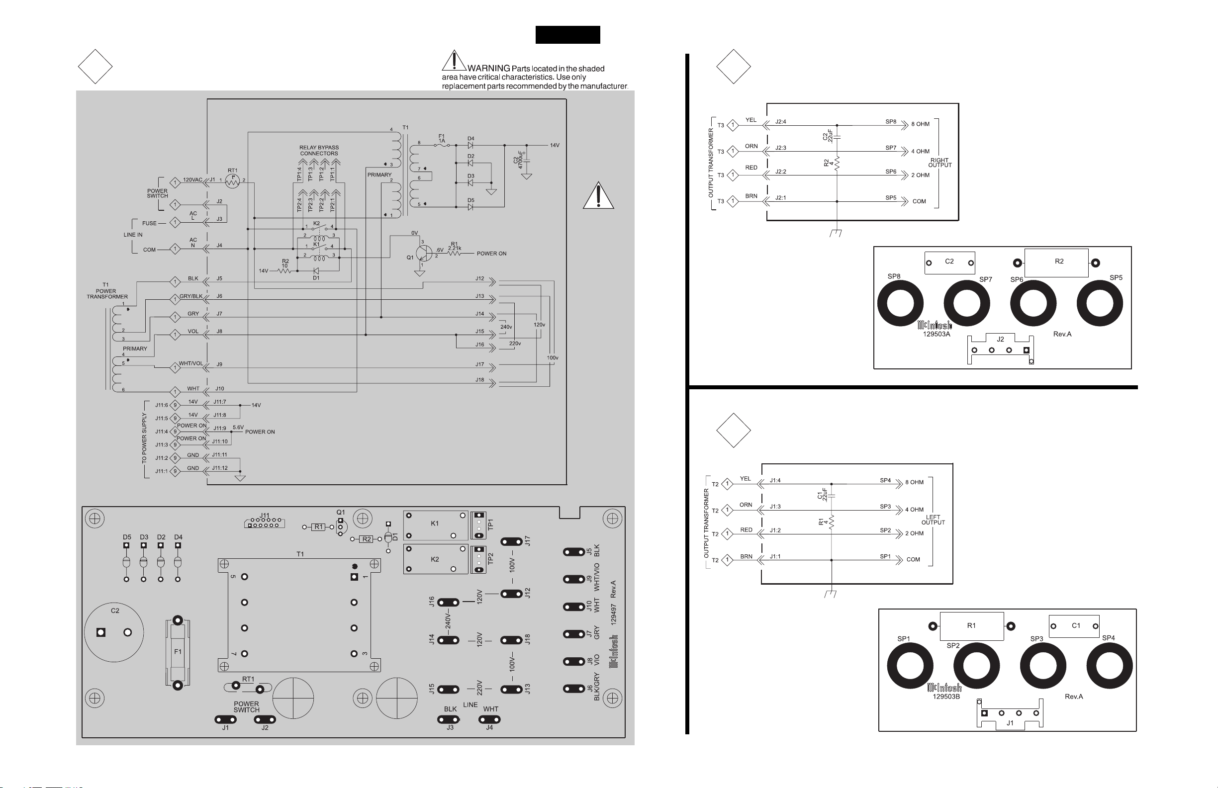
9
049972 POWER SUPPL Y PCB
C1 CAP MONO .47uF 50V 061249
C2 CAP POLY .047UF 10% 1000VDC 064434
C3 CAP ELECT 680UF 315V 066549
C4 CAP ELECT 680UF 315V 066549
C5 CAP ELECT 47UF 450V 066497
C6 CAP ELECT 33UF 500V 066542
C7 CAP ELECT 47UF 450V 066497
C8 CAP ELECT 1UF 50V 066510
C9 CAP ELECT 680UF 315V 066549
C10 CAP ELECT 680UF 315V 066549
C11 CAP ELECT 4700UF 35V 066541
C12 CAP ELECT 10UF 50V 066445
C13 CAP POLYPROP .047UF 10% 250VDC 064364
C14 CAP ELECT 4700UF 35V 066541
C15 CAP ELECT 10UF 50V 066445
D1 DIODE BRID RECT 1000V 6A 070165
D2 DIODE ZENER 150V 070170
D3 DIODE ZENER 150V 070170
D4 DIODE RECTIFIER 1N4007 070169
D5 DIODE RECTIFIER 1N4007 070169
D6 DIODE SIL 400 PIV @ 1.5A 070031
D7 DIODE SIL 400 PIV @ 1.5A 070031
D8 DIODE SIL 400 PIV @ 1.5A 070031
D9 DIODE SIL 400 PIV @ 1.5A 070031
D10 DIODE SILICON 070047
F1 FUSE 2A 250V SLO-BLO 5X20 IEC 089088
F2 FUSE 2A 250V SLO-BLO 5X20 IEC 089088
GP1 BRACKET PCB CARD MOUNTING 003611
GP2 BRACKET PCB CARD MOUNTING 003611
J1 BLADE FASTON .187 117726
J2 BLADE FASTON .187 117726
J3 BLADE F AST ON W/FEET 117708
J4 BLADE F AST ON W/FEET 117708
J5 BLADE F AST ON W/FEET 117708
J6 BLADE F AST ON W/FEET 117708
J7 BLADE F AST ON W/FEET 117708
J8 BLADE F AST ON W/FEET 117708
J9 BLADE F AST ON W/FEET 117708
J10 BLADE FAST ON W/FEET 117708
J11 CONN 12 PIN FFC 117720
J12 BLADE FAST ON W/FEET 117708
J13 BLADE FAST ON W/FEET 117708
J14 BLADE FAST ON W/FEET 117708
J16 CONN PCB MOUNT POWER RED 117719
J17 CONN PCB MOUNT POWER RED 117719
J18 HEADER 9 CIRCUIT POST NATURAL 117724
Q1 TRANSISTOR: NPN POWER 132295
Q2 TRANSISTOR NPN 132223
Q3 TRANSISTOR PNP 132224
Q6 TRANSISTOR P FET 1-4PO 250 OHM 132220
R1 RES MO 18K 5% 1W 144286
R2 RES MO 100K 5% 2W 144438
R4 RES MF 2.74M 1/4W 144271
R5 RES MF 100K 1% 1/4W 144113
R6 RES MF 100K 1% 1/4W 144113
R7 RES MF 1M 1/4W 144269
R8 RES MF 221K 1% 1/4W 144421
R9 RES MF 100K 1% 1/4W 144113
R10 RES MO 2.2K 5% 2W 144494
R75 RES MO 100K 5% 2W 144438
R76 RES MO 100K 5% 2W 144438
U2 IC REGULATOR 15V 133154
U3 IC REGULATOR -15V 133153
10
049973 METER PCB
C1 CAP MONO .1uF 50V 20% Z5U 061305
C2 CAP MONO .1uF 50V 20% Z5U 061305
C3 CAP MONO .1uF 50V 20% Z5U 061305
C4 CAP ELECT 100UF 25V 066161
C5 CAP MPF 0.1UF 100V 064337
C6 CAP MPF 0.22UF 5% 63VDC 064329
C7 CAP MPF 0.1UF 100V 064337
C8 CAP MPF 0.22UF 5% 63VDC 064329
C9 CAP ELECT 2.2UF 50V 066511
C10 CAP ELECT 2.2UF 50V 066511
D1 DIODE ZENER 5V 070132
D2 DIODE SILICON 070047
D3 DIODE SILICON 070047
D4 DIODE SILICON 070047
D5 DIODE SILICON 070047
D6 DIODE SILICON 070047
D7 DIODE SILICON 070047
D8 DIODE SILICON 070047
D9 DIODE SILICON 070047
D10 DIODE SILICON 070047
D11 DIODE SILICON 070047
D12 DIODE SILICON 070047
D13 DIODE SILICON 070047
DS1 LED BLUE 5MM HI-INTENSITY 058166
DS2 LED GREEN 5MM HI-INTENSITY 058165
DS3 LED BLUE 5MM HI-INTENSITY 058166
DS4 LED GREEN 5MM HI-INTENSITY 058165
DS5 LED BLUE 5MM HI-INTENSITY 058166
DS6 LED GREEN 5MM HI-INTENSITY 058165
DS7 LED BLUE 5MM HI-INTENSITY 058166
DS8 LED GREEN 5MM HI-INTENSITY 058165
J2 BLADE F AST ON W/FEET 117708
J3 CONN 12 PIN FFC 117720
J4 CONN 3 POS MALE MTS100 NORMAL 117214
J5 HEADER 2 PIN LATCHING 117766
J6 HEADER 2 PIN LATCHING 117766
J7 BLADE F AST ON W/FEET 117708
Q1 TRANSISTOR NPN 132223
Q2 TRANSISTOR NPN 132223
Q3 TRANSISTOR NPN 132254
Q4 TRANSISTOR NPN 132254
Q5 TRANSISTOR NPN 132254
Q6 TRANSISTOR NPN 132254
Q7 TRANSISTOR NPN 132223
Q8 TRANSISTOR NPN 132223
Q9 TRANSISTOR NPN 132223
R1 RES MF 475 OHM 1% 1/4W 144086
R2 RES MF 10 OHM 1% 1/4W 144157
R3 RES MF 22.1K 1% 1/4W 144187
R4 RES MF 22.1K 1% 1/4W 144187
R5 RES MF 68.1K 1% 1/4W 144081
R6 RES MF 68.1K 1% 1/4W 144081
R7 RES MF 10.2K 1% 1/4W 144130
R8 RES MF 10.2K 1% 1/4W 144130
R9 RES MF 10M 1% 1/4W 144264
R10 RES MF 121K 1% 1/4W 144418
R11 RES MF 10M 1% 1/4W 144264
R12 RES MF 121K 1% 1/4W 144418
R13 POT TRIM 100K OHM 20% 134383
R14 POT TRIM 100K OHM 20% 134383
R15 RES MF 100 OHM 1% 1/4W 144196
R16 RES MF 100 OHM 1% 1/4W 144196
R17 RES MF 221K 1% 1/4W 144421
R18 RES MF 2.21M 1/4W 144265
R19 RES MF 2.21M 1/4W 144265
R20 RES MF 187K 1% 1/4W 144406
R21 RES MF 187K 1% 1/4W 144406
R22 RES MF 4.75K 1% 1/4W 144097
R23 RES MF 1.21K 1% 1/4W 144191
R24 RES MF 10K 1% 1/4W 144053
R25 RES MF 4.75K 1% 1/4W 144097
R26 RES MF 1.21K 1% 1/4W 144191
R27 RES MF 10K 1% 1/4W 144053
R28 POT TRIM 500 OHM 20% HORIZ ADJ 134410
R29 POT TRIM 500 OHM 20% HORIZ ADJ 134410
R30 POT TRIM 500 OHM 20% HORIZ ADJ 134410
R31 POT TRIM 500 OHM 20% HORIZ ADJ 134410
R32 RES MF 221 OHM 1% 1/4W 144172
R33 RES MF 221 OHM 1% 1/4W 144172
R34 RES MF 221 OHM 1% 1/4W 144172
R35 RES MF 221 OHM 1% 1/4W 144172
U1 IC DUAL OPERATIONAL AMPLIFIER 133260
U2 IC DUAL OPERATIONAL AMPLIFIER 133260
11
050007 BACKUP POWER SUPPLY PCB
C2 CAP ELECT 4700UF 35V 066541
D1 DIODE SILICON 070047
D2 DIODE SIL 400 PIV @ 1.5A 070031
D3 DIODE SIL 400 PIV @ 1.5A 070031
D4 DIODE SIL 400 PIV @ 1.5A 070031
D5 DIODE SIL 400 PIV @ 1.5A 070031
F1 FUSE 1A 250V SB 5X20 IEC 089107
J1 BLADE F AST ON W/FEET 117708
J2 BLADE F AST ON W/FEET 117708
J3 BLADE F AST ON W/FEET 117708
J4 BLADE F AST ON W/FEET 117708
J5 BLADE F AST ON W/FEET 117708
J6 BLADE F AST ON W/FEET 117708
J7 BLADE F AST ON W/FEET 117708
J8 BLADE F AST ON W/FEET 117708
J9 BLADE F AST ON W/FEET 117708
J10 BLADE F ASTON W/FEET 117708
J11 CONN 12 PIN FFC 117720
J12 BLADE FASTON W/FEET 117708
J13 BLADE F ASTON W/FEET 117708
J14 BLADE F ASTON W/FEET 117708
J15 BLADE FASTON W/FEET 117708
J16 BLADE F ASTON W/FEET 117708
J17 BLADE F ASTON W/FEET 117708
J18 BLADE F ASTON W/FEET 117708
K1 RELA Y POWER TV5 12V 087070
K2 RELA Y POWER TV5 12V 087070
Q1 TRANSISTOR NPN 132223
R1 RES MF 2.21K 1% 1/4W 144298
R2 RES MF 10 OHM 1% 1/4W 144157
RT1 THERMISTER 5 OHM 144151
T1 TRANSFORMER LOW PROFILE 159342
TP1 CONN 4 PIN 117215
TP2 CONN 4 PIN 117215
12
050052 TERMINAL PCB
13
C1 CAP MPF 0.22UF 400VDC 064438
C2 CAP MPF 0.22UF 400VDC 064438
J1 HEADER 4 CIRCUIT POST 117772
J2 HEADER 4 CIRCUIT POST 117772
R1 RES WW 4 OHM 5% 5W 139119
R2 RES WW 4 OHM 5% 5W 139119
4847
Page 25

EXPLODED VIEW and PARTS LIST
MA2275
(4X)
33
40
39
41
(4X)
33
(4X)
42
(6X)
32
(6X)
(4X)
14
15
(4X)
(6X)
11
16
5
4
(4X)
3
13
10
9
8
7
6
14
(4X)
20
11
2
1
7
11
12
24
19
17
21
11
(4X)
10
8
9
24
31
18
22
(3X)
30
2827
(3X)(3X)
23
(6X)
25
38
39
36
34
35
30
29
26
(6X)
(8X)
37
33
31
55
75
72
73
(6X)
72
33
(4X)
40
(4X)
82
(4X)
81
(4X)
80
(11X)
79
78
77
(4X)
55
(6X)
68
74
76
(8X)
71
68
53
77
(2X)
(13X)
45
33
(5X)
55
46
57
54
48
47
(3X)
(4X)
63
(4X)
64
62
63
59
58
(3X)
77
49
50
52
(4X)
65
REF
57
66
52
61
60
61
56
55
(4X)
53
51
(4X)
65
(3X)
(4X)
63
64
55
63
(3X)
59
(9X)
67
52
62
(4X)
55
60
(4X)
70
68
69
(6X)
50
43
44
(3X)
5049
Page 26

EXPLODED VIEW con’t and PARTS LIST
Ref
No.
Part
No.
Description
1 016495 GLASS
2 171026 CABLE ASSY POWER SWITCH
3 017531 PUSHBUTTON ASSY RED
4 017517 PUSHBUTTON ASSY BLK
5 078033 O-RING
6 017854 BEZEL HEADPHONE
7 094360 TAPE FOAM 1/2 X 1/2
8 004939 BRACKET EXTRUSION
9 018515 END CAP 9”
10 101042 SCREW TS 4-40 X 1/2 SLOT FILL
11 094016 TAPE FOAM 1/4 X 1/8
12 098113 CORD DIAL .027 BLK BRAID SILK
13 018706 EXTRUSION BOTTOM
14 100149 SCREW MACH 6-32 X 1/4 FL U/H ST
15 018738 EXTRUSION TOP
16 092443 FILTER METER
17 078037 O-RING
18 049970 ASSY PUSHBUTTON PCB
19 017191 BUMPER BUTTON
20 017921 LOGO/SELECTOR BACKLIGHT
21 017901 LOGO/ PUSHBUTTON BACKLIGHT
22 017907 TITLE/PUSHBUTTON BACKLIGHT
23 094431 TAPE FOAM WHT 3/8W X 1/32 THK
24 094430 TAPE FOAM WHT 1/2 W X 1/8 THK
25 005347 SUBPANEL
26 049966 ASSY CONTROL PCB
27 110004 NUT CONTROL M7 X 0.75 HEX
28 104013 WASHER LOCK 5/16 X .435 X .002
29 110002 NUT CONTROL M9 X 0.75 PLATED
30 104014 WASHER INT STAR 3/8 X .507 X .002
31 101054 SCREW TAPTITE 6-32 X 1/4 PH PN BLK
32 112060 SPACER 4 X 5/16 STEEL
33 102001 NUT KEP 4-40 CADMIUM PLATE
34 005390 SWITCH PLATE
35 021159 BUSHING SWITCH
36 146243 SWITCH POWER
37 049968 ASSY VOLUME/TONE PCB
38 124087 METER MA2275
39 017922 METER BACKLIGHT
40 005391 METER PLATE
41 049973 ASSY METER PCB
42 112038 SPACER STEEL 4 X 3/8 NICKEL PLATE
43 005346 CHASSIS
44 078031 GROMMET RUBBER 1” ID
45 017895 SPACER NYLON 6-32 X 7/16
46 117755 RECEPTACLE INPUT & LINE FILTER
47 100178 SCREW MACH 4-40 X 3/8 PH PN
48 178161 HOLDER FUSE 5 X 20mm IEC
49 104016 WASHER INT STAR .5 X .630 X .022
50 102003 NUT MACH 6-32 W/LOCK
51 084112 POST GROUND GOLD
52 100250 SCREW MACH SEMS 6-32 X 1/4 PH PN
53 049971 ASSY AMP PCB
54 049954 ASSY MAIN PCB
55 100157 SCREW MACH 6-32 X 1/4 PH PN
56 049967 ASSY BALANCED PCB
57 049969 ASSY DATA PCB
58 017673 SPACER .380 ID X 3/8 L PHENOLIC
59 117740 POST BINDING RED
60 117741 POST BINDING BLK
61 104178 WASHER LOCK M10 EXT STAINLESS
62 102052 NUT GOLD SUPPLIED W/117758
63 104162 WASHER LOCK INTERNAL T OOTH
64 050052 ASSY TERMINAL PCB
65 102051 NUT HEX M9 X 0.75 GOLD PLATED
66 104014 WASHER INT STAR 3/8 X .507 X .002
67 101197 SCREW HI/LO 4-24 X 3/8 PH RD BLK
68 102006 NUT MACH 10-32 W/LOCK
69 021092 SPACER 6 X 5/16
70 122379 CHOKE FILTER
71 050007 ASSY BACKUP POWER SUPPLY PCB
72 102045 NUT KEP 6-32 SPECIAL
73 049972 ASSY POWER SUPPLY PCB
74 005348 SUPPORT BRACKET
75 005395 POWER SUPPLY SHIELD
76 021030 SPACER 6 X 1/4
77 017160 TAB MOUNTING .140 DIA MTG
78 005350 BOTTOM COVER
79 101078 SCREW TAP 8-32 X 5/16 PH PN BLK
80 017841 FOOT
81 100159 SCREW MACH 10-32 X 3/4 PH PN BLK
82 024010 FOOT PAD
83 017761 AIR PIPE
84 100292 SCREW MACH 6-32 X 3/8 PH FH BLK
85 165069 TUBE KT88 MCINTOSH
86 165065 TUBE 12AX7A MCINTOSH
87 165067 TUBE 12AT7
88 050042 POTTED TRANSFORMER OUTPUT
89 050041 POTTED TRANSFORMER POWER
90 126986 DECAL OUTPUT TRANSFORMER
91 126985 DECAL POWER TRANSFORMER
92 005349 TUBE COVER
93 017862 FOOT PUSH-ON
94 005389 DUST COVER
95 126987 DECAL TOP COVER
96 100287 SCREW MACH 8-32 X 3/8 PH TR HD
97 101232 SCREW 6-32 X 1/4 PHIL FLAT
98 104017 WASHER FELT BLK 3/4 X 1/4 X 1/16
99 049695 ASSY KNOB 34 INDEX METRIC
100 049694 ASSY KNOB 21 INDEX METRIC
101 049637 ASSY KNOB 34 METRIC W/O INDEX
102 050055 ASSY KNOB 21 INDEX AMER
5251
Page 27

REPACKING INSTRUCTIONS
MA2275
53
Page 28

TUBE INTEGRATED AMPLIFIER
SERVICE MANUAL
The continuous improvement of its products is the policy of McIntosh Laboratory Incorporated, who reserve the right to improve design without
notice. Because of the constant upgrading of McIntosh products’ circuitry and components, the Company cannot insure, and does not warrant, the
accuracy of the within schematic material, which is intended for information only.
McINTOSH LABORATORY, INC., 2 CHAMBERS STREET, BINGHAMTON, NEW YORK 13903 Printed in U.S.A. Part Number 040916
 Loading...