

McIntosh CK-340 Owners manual
In Wall
Mounting Kit
with Grille
CK320
yy
yCK340
yy
yy
yCK350
yy
Installation Guide
McIntosh Laboratory, Inc. 2 Chambers Street Binghamton, New York 13903-2699 Phone: 607-723-3512 FAX: 607-724-0549
Installation
The following instructions are for installing the XLS320,
XLS340, and XCS350 Loudspeaker Systems into the wall using
the optional CK320, CK340 and CK350 In Wall Mounting Kits
with Grilles. The CK320, CK340 and CK350 Kits share a common mounting procedure with a varying number of mounting
brackets and fasteners used to install each Loudspeaker Model.
Before proceeding with these instructions refer to the
XLS320, XLS340 and XCS350 Owner’s Manual sections including “Unpacking the Loudspeaker” starting on page 10, to
“Locating the Loudspeaker System” on page 18, “Tweeter Array
Optimization” on page 19 and “How to Connect” starting on
page 20, before beginning the Mounting Process. It is recommended that the Professionals at your McIntosh Dealer, who are
skilled in all aspects of installation and operation, install the
Loudspeaker System and any associated audio/video equipment.
Caution: Due to the size and weight of the XLS340 and
XCS350 Loudspeakers, two or more persons may
be required to install them safely.
Unpacking the Loudspeaker
Unpacking the XLS320, XLS340 and XCS350 Loudspeaker by
referring to the instructions contained in the Owner’s Manual
starting on page 10. Then perform the following steps:
1. Place the Loudspeaker System, with the front facing
down, on top of the packing material located on top of the
shipping carton
as illustrated in
the Owner’s
Manual.
2. Using the supplied
Allen Wrench, remove the screws
at locations illustrated in figure
1.
Note: The
XCS350
Loudspeaker
requires
removal of
the
Stabilizer
Bar and
replacement
of the three
screws
used to
attach the
Stabilizer
Bar, with
screws of the same
type but shorter in
length (supplied
with the XCS350) to prevent
air leaks.
Screw Removal Location
XLS340
Remove Screws
Remove Screws
Figure 1
XCS350
Remove Screws
Remove Screws
XLS320
Remove Screws
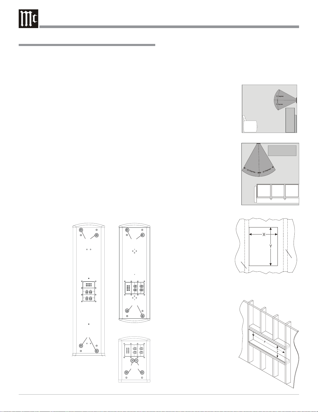
Installing the Loudspeaker System
The XLS320, XLS340 and XCS350 Loudspeakers’ Smooth Frequency Response may be altered by a large object(s) located in
the sound waves path or by locating the Loudspeaker too close
to a side wall. There should be an unobstructed area in front of
the Loudspeaker of at least 15 degrees either top or bottom from
the center axis and 30 degrees side
to side for the best performance. Refer to figures 2 and 3.
3. Use a suitable wall stud finder
or metal detector to verify a
proper mounting location for
the Loudspeaker System before cutting into the wall. The
XLS320 and XLS340 are de-
Figure 2
signed for mounting between
vertical wall studs with 16
inch (40.64cm) centers. Refer
to figure 4. The XCS350 is
designed for mounting horizontally in a special prepared
opening. Refer to figure 5.
Note: Make sure there are
no Plumbing Pipes, AC
Electrical Wiring or
Heating/Cooling
Ductwork in the wall
Figure 3
between the studs
where the
Loudspeaker is to be
mounted.
4. For the XLS320 and
XLS340, cut an opening in
the existing finished wall
using the dimensions in the
Stud
Stud
figure 6 Chart. The In Wall
Mounting Bracket(s) can be
oriented for anchoring the
Figure 4
Bracket to the wall stud either on the left or right hand
side of the Loudspeaker. Refer to the Top Inside Views in
figures 7 and 8.
Note: The In Wall
Bracket(s) must be
secured to a wall stud
on one side, with the
other side clamped to
the dry wall. In new
construction the
Loudspeaker
Mounting Bracket(s)
should be secured to
wall studs on both
sides.
5. To mount the XCS350 Hori-
Figure 5
zontally requires wall con-
2
 Loading...