

Maxdata 100 I M9 user manual

MAXDATA PLATINUM 100 I
User’s Manual
Rev. 1.1

2 3MAXDATA PLATINUM 100 I M9Contents

Contents
1 Setting up the System 5
Safety Information ...................................................................................................................................5
Server Position ...................................................................................................................................5
System Access Warnings ..................................................................................................................6
Connecting the System ...........................................................................................................................7
Back Panel Connectors ......................................................................................................................7
Powering up the System .........................................................................................................................8
2 Server Features 9
Connector and Header Locations ..........................................................................................................10
Configuration Jumpers ..........................................................................................................................11
SSI Front Panel Connector ....................................................................................................................11
Hardware Requirements .......................................................................................................................12
Processor .........................................................................................................................................12
Memory ............................................................................................................................................12
Supported Memory Modules ...........................................................................................................12
Optional Hardware ................................................................................................................................12
Remote Management Module .........................................................................................................12
3 Hardware Installations and Upgrades 13
Before You Begin ..................................................................................................................................13
Tools and Supplies Needed ..............................................................................................................13
Installing or Replacing a Processor ........................................................................................................13
Installing a Processor .......................................................................................................................13
Installing the Heat Sink ..........................................................................................................................16
Removing a Processor .....................................................................................................................17
Installing a PCI Card ..............................................................................................................................17
Installing and Removing Memory ..........................................................................................................18
Installing DIMMs ..............................................................................................................................18
Replacing the Backup Battery ...............................................................................................................19
4 Server Utilities 21
Using the BIOS Setup Utility .................................................................................................................21
Starting Setup ...................................................................................................................................21
If You Cannot Access Setup .............................................................................................................21
Setup Menus .................................................................................................................................... 21
Clearing the CMOS ...............................................................................................................................23
Configuring the System for embedded Serial ATA RAID ......................................................................24
Configuring the BIOS .......................................................................................................................24
Creating Intel® Matrix Storage Technology RAID set .......................................................................24
Creating LSI Technology RAID set ...................................................................................................24
Loading the RAID Drivers (Windows Server 2003) ..........................................................................25
5 Technical Reference 27
Power Supply Specifications .................................................................................................................27
300 W Single Power Supply Input Voltage .......................................................................................27
300 W Single Power Supply Output Voltages .................................................................................. 27

6 Regulatory and Compliance Information 29
Product Regulatory Compliance ............................................................................................................29
Product Safety Compliance ..............................................................................................................29
Product RoHS Compliance ...............................................................................................................29
Product EMC Compliance ...............................................................................................................29
Product Regulatory Compliance Markings .......................................................................................29
Electromagnetic Compatibility Notices .................................................................................................29
Europe (CE Declaration of Conformity) ............................................................................................29
Figures
1. Back Panel Connectors .....................................................................................................................7
2. PLATINUM 100 I Controls ................................................................................................................. 8
3. Board Connector and Component Locations ..................................................................................10
4. Configuration Jumpers ....................................................................................................................11
5. SSI Front Panel Connector ..............................................................................................................11
6. Opening the Processor Socket Lever ..............................................................................................13
7. Opening Load Plate .........................................................................................................................14
8. Removing Protective Covering from the Load Plate .......................................................................14
9. Inserting the Processor ...................................................................................................................14
10. Closing Load Plate and Socket Lever ..............................................................................................15
11. Installing the Heat Sink ....................................................................................................................16
12. Installing DIMMs .............................................................................................................................18
13. Removing the Battery .....................................................................................................................20
Tables
1. NIC LEDs ........................................................................................................................................... 7
2. Feature Summary .............................................................................................................................. 9
3. Board Connectors and Components ...............................................................................................10
4. Keyboard Commands ......................................................................................................................22
5. 300 W Power Supply Output Rating ...............................................................................................27
6. Product Certification Markings ........................................................................................................29
4 PBMAXDATA PLATINUM 100 I M9Contents
1 Setting up the System
Safety Information
Server Position
Please take note of the following criteria for creating a practical and safe workplace when setting up
your computer:
!
CAUTION
The system can be used anywhere the temperature is suitable for people. However, rooms with
humidity over 70%, and dusty or dirty areas are not appropriate. In addition, do not expose the server
to any temperatures over +30°C or under +10°C.
!
CAUTION
For proper cooling and airflow, operate the system only with the chassis covers installed.
!
CAUTION
Make sure that the cables connecting the server to peripheral devices are not tight.
!
CAUTION
Make sure that all power and connection cables are positioned so that they are not trip hazards.
!
CAUTION
When you save data to your server‘s hard disks or to a floppy disk, they are stored as magnetic
information on the media. Make sure that they are not damaged by magnetic or electromagnetic
fields.
!
CAUTION
Because the electronics in your computer can be damaged by jarring, no mechanical devices should
be placed on the same surface as the server. This is especially important for impact printers whose
vibrations could damage the hard disk.
!
CAUTION
Hazardous conditions, devices and cables: Hazardous electrical conditions may be present on
power, telephone, and communication cables. Turn off the server and disconnect the power cord,
telecommunications systems, networks, and modems attached to the server before opening it.
Otherwise, personal injury or equipment damage can result.
!
CAUTION
Electrostatic discharge (ESD) and ESD protection: ESD can damage disk drives, boards, and other
parts. We recommend that you perform all procedures in chapter 3 only at an ESD workstation. If one
is not available, provide some ESD protection by wearing an antistatic wrist strap attached to chassis
ground ‑ any unpainted metal surface ‑ on your server when handling parts.
!
ATTENTION
In order to fully separate the server from current, the power cord must be removed from the wall
outlet.

System Access Warnings
!
CAUTION
To avoid personal injury or property damage, the following safety instructions apply whenever accessing
the inside of the product:
• Turn off all peripheral devices connected to this product.
• Turn off the system by pressing the power button to off.
• Disconnect the AC power by unplugging all AC power cords from the system or wall outlet.
• Disconnect all cables and telecommunication lines that are connected to the system.
• Retain all screws or other fasteners when removing access cover(s). Upon completion of
accessing inside the product, refasten access cover with original screws or fasteners.
• Do not access the inside of the power supply. There are no serviceable parts in the power
supply. Return to manufacturer for servicing.
• Power down the server and disconnect all power cords before adding or replacing any non hot‑
plug component.
• When replacing a hot‑plug power supply, unplug the power cord to the power supply being
replaced before removing the power supply from the server.
!
CAUTION
If the server has been running, any installed processor(s) and heat sink(s) may be hot. Unless you
are adding or removing a hot‑plug component, allow the system to cool before opening the covers.
To avoid the possibility of coming into contact with hot component(s) during a hotplug installation,
be careful when removing or installing the hot‑plug component(s).
!
CAUTION
To avoid injury do not contact moving fan blades. If your system is supplied with a guard over the
fan, do not operate the system without the fan guard in place.
6 7MAXDATA PLATINUM 100 I M9Setting up the System
Connecting the System
A
B
D
F
C
E
G
H
I
J
K L
M
N
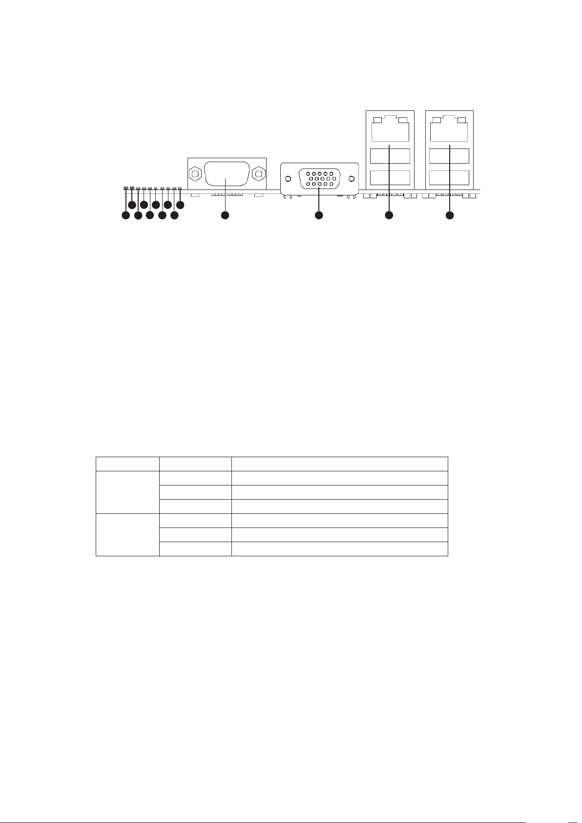
Back Panel Connectors
Figure 1. Back Panel Connectors
A. System Identification LED H. Diagnostic LED 2
B. Status LED I. Diagnostic LED 1
C. Diagnostic LED 7 (MSB LED) J. Diagnostic LED 0 (LSB LED)
D. Diagnostic LED 6 K. Serial Port A
E. Diagnostic LED 5 L. Video Port
F. Diagnostic LED 4 M. NIC 1 (top, default management port),
G. Diagnostic LED 3 N. NIC 2 (top), two USB ports (bottom)
two USB ports (bottom)
The NIC LEDs at the right and left of each NIC provide the following information.
Table 1. NIC LEDs
LED LED State Description
Left Off No network connection
Solid Green Network connection in place
Blinking Green Transmit/receive activity
Right Off 10 Mbps connection (if left LED is on or blinking)
Solid Green 100 Mbps connection
Solid Amber 1000 Mbps connection
Powering up the System
A
B
C
D
E
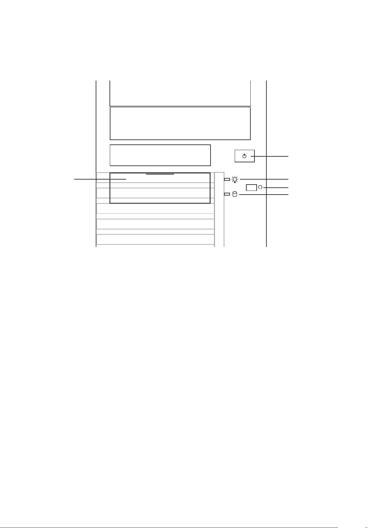
At the front of the case, you can find the necessary controls like power button and the HDD LEDs.
Press the power button one time briefly in order to boot the server.
Figure 2. PLATINUM 100 I Controls
A. Front USB ports
B. Power switch
C. Power LED
D. Reset switch
E. HDD LED
8 PBMAXDATA PLATINUM 100 I M9Setting up the System
2 Server Features
This chapter briefly describes the main features of the server system. This chapter provides a list of
server system features and diagrams showing the location of important components and connections
of the server system.
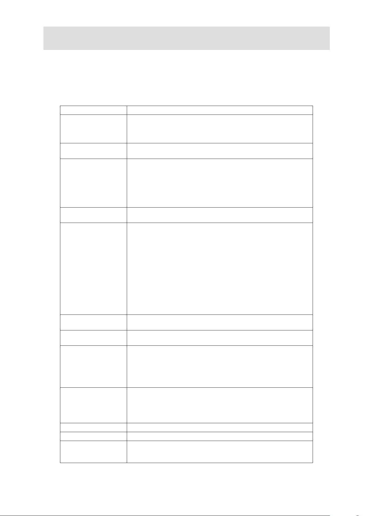
Table 2 summarizes the features of the server system.
Table 2. Feature Summary
Feature Description
Chassis Dimensions 450 mm high
195 mm wide
501 mm deep
18.0 kg max. chassis weight
Processor • Support for one Intel® Xeon® 3400 Series Processor
• LGA 1156 socket
Memory Two memory channels with support for 1066/1333 MHz ECC Unbuff-
ered DDR3 DRAM (UDIMM) or ECC Registered DDR3 DRAM (RDIMM,
Intel® Xeon® 3400 Series only).
• Up to 2 UDIMMs or 3 RDIMMs (Intel® Xeon® 3400 Series only) per
channel
• 32 GB max with x8 ECC RDIMM (2 Gbit DRAM) and 16 GB max with
x8 ECC UDIMM (1 Gbit DRAM)
Chipset • Intel® 3420 Chipset Platform Controller Hub (PCH)
• ServerEngines LLC Pilot II BMC controller (Integrated BMC)
Peripheral Interfaces External connections:
• One DB-15 graphics port
• One DB-9 serial port A
• Two RJ45 network ports for 10/100/1000 Mbps
• Four USB 2.0 ports (back panel)
• Two USB 2.0 ports (front)
Internal connections:
• One 2x5 USB connector for two USB 2.0 ports
• One vertical type A USB connector
• One 2x5 connector for serial port B
• Six SATA-II ports with integrated RAID support
(Matrix Storage Raid Technology, Raid 0, 1, 5, 10)
• One port for a remote management module 3 (optional)
Video
LAN • One Gigabit Ethernet 82574L controller
Expansion Capabilities • Slot 1: 5V PCI 32 bit / 33 MHz
Hard Drives • up to four SATA-II hard drives
Power supply Efficient 300 W power supply (80 PLUS®)
Fans Support for two system fans and one processor fan
System Management Integrated IPMI 2.0-compliant baseboard management controller
On-board controller ServerEngines LLC Pilot II with integrated 2D video
controller, 64 MB DDR2 memory, 8 MB of which is graphics memory
• One Gigabit Ethernet 82578DM controller
• Slot 2: PCI Express Gen1 x4 (x1 connection, optional)
• Slot 3: PCI Express Gen1 x8 (x4 connection)
• Slot 4: PCI Express Gen2 x8 (x4 connection, optional)
• Slot 5: PCI Express Gen2 x8 (x8 connection)
• Slot 6: PCI Express Gen2 x16 (x8 connection)
• up to two internal SATA hard drives
• support for optional 3x hot-swap drive cage (occupies two
5,25” bays)
• support for optional internal 4x drive cage
•
Support for remote management module 3 (“KVM over IP”, optional)
• Support for system management software
 Loading...