

MAXDATA PLATINUM 100 I – Quick Start Guide
A
B
C
D
E
C
D
B
E
A
A B F G H
CC
Y
DD
V W U R S N O Q P M L
J
I
K
E D C
AA
Z
BB
X T
HH
II
GG
FF
EE
Thank you for buying a MAXDATA PLATINUM 100 I Server. This document describes how to set up the
system, turn on the system, and complete configuration for the system.
Please go to “http://www.maxdata.com/” >> “Downloadservice” >> “MAXDATA Platinum Server” >> “Manuals” to download a manual containing additional information.
Safety
Warning
Installation and service
Installation and service of this product is to be performed only by qualified service
personnel to avoid risk of injury from electrical shock or energy hazard.
Enclosure cover
In order to comply with applicable safety, emission, and thermal requirements, no covers
should be removed and all bays must be fitted with drive carriers.
Battery Safety
There is a danger of explosion if the battery is incorrectly replaced.
Dispose of used batteries in accordance with the manufacturer’s instructions and national
regulations.
Caution
Electrostatic discharge
Observe normal Electrostatic Discharge (ESD) procedures during system integration
to avoid possible damage to the server board and/or other components of the server
system.
Server system power
System power on/off: The power button DOES NOT turn off the system AC power. To
remove power from server system, you must unplug the AC power cord from the wall
outlet or the chassis.
Safety instruction for upright system
To ensure stability, the floor stands must be turned outwards.
Site Selection
The system is designed to operate in a typical office environment. Choose a site that is:
• Clean, dry, and free of airborne particles (other than normal room dust).
• Well-ventilated and away from sources of heat including direct sunlight and radiators.
• Away from sources of vibration or physical shock.
• Isolated from strong electromagnetic fields produced by electrical devices.
• Provided with a properly grounded wall outlet.
• Provided with sufficient space to access the power supply cord(s), because they serve as the
product’s main power disconnect.
In regions that are susceptible to electrical storms, we recommend you plug your system into a
surge suppresser and disconnect telecommunication lines to your modem during an electrical
storm.
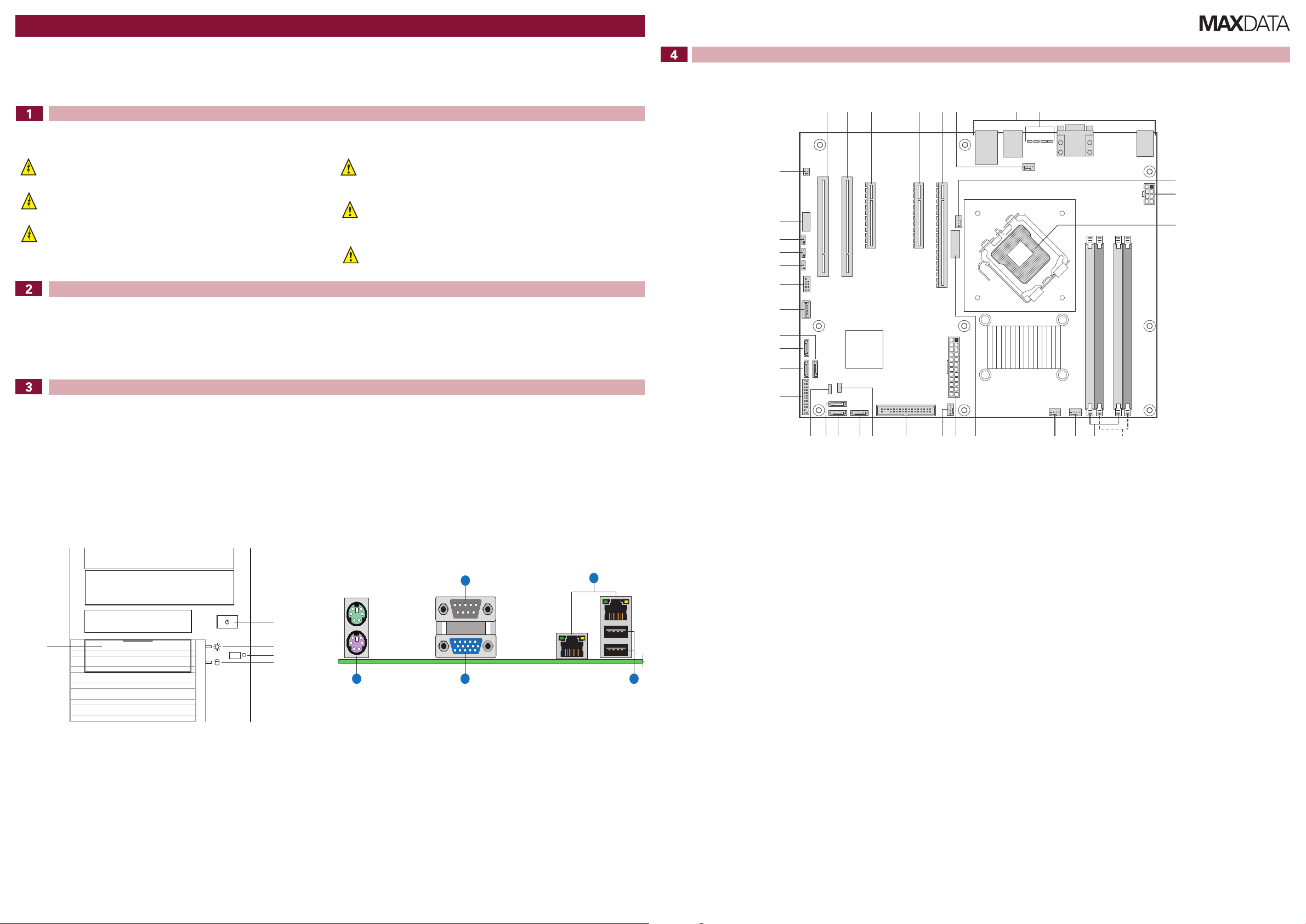
Server Board Connector and Component Locations
System Overview
Technical Specification
Dimensions (upright configuration):
- 450 mm high
- 195 mm wide
- 501 mm deep
- 18 kg max. weight
System Power:
- Single Power Supply
200-240 V at 50/60 Hz; 3 A max.
Temperature Range: +10 °C to +30 °C
Front Controls
A. Front USB ports
B. Power switch
C. Power LED
D. Reset switch
E. HDD LED
Regulatory Compliance
This product complies to the following requirements:
- EN 60950 – Safety
- EN 55022 – Emissions
- EN 55024 – Immunity
- EN 61000-3-2 – Harmonics
- EN 61000-3-3 – Voltage Flicker
- CE – EMC Directive 89/336/EEC
This product has a CE declaration of conformity (CENELEC Europe).
This server system is compliant to European Directive 2002/95/EC (RoHS).
A. PCI (5V/32bit/33MHz) Slot 1 S. Floppy Connector
Back Panel Connectors
A. Stacked PS2 Mouse/Keyboard Ports D. NIC 1/2 (10/100/1000 Mbps)
B. Serial A E. USB1-2
C. Video
B. PCI (5V/32bit/33MHz) Slot 2 T. HSBP
C. PCI Express x8 U. SATA 0
D. PCI Express x8 V. SATA1
E. PCI Express x16 W. SATA 2
F. System Fan 1 Connector X. IPMB
G. Back Panel Connectors Y. Front Panel Header
H. Diagnostic LEDs Z. SATA 4
I. Processor Fan 1 Connector AA. SATA 5
J. 2x4 Aux Power Connector BB. SATA 3
K. Processor Socket CC. Internal USB
L. Channel 2 DIMM Sockets DD. External USB
M. Channel 1 DIMM Sockets EE. CMOS Clear Jumper
N. System Fan 4 Connector FF. Password Clear Jumper
O. System Fan 3 Connector GG. BIOS Recovery Jumper
P. Battery HH. Serial Port
Q. Main Power Connector II. Chassis Intrusion Header
R. System Fan 2 Connector
MAXDATA PLATINUM 100 I M8 Quick Start Guide
 Loading...