

Page 1

Contents
FCC Class B/European CE Compliance ............................... 3
Introduction ...................................................................... 4
What’s In the Box ............................................................... 4
Quick Start ........................................................................ 5
About the DMAN .............................................................. 5
Digital Audio Features of DMAN ....................................... 6
About Plug-and-Play ......................................................... 7
The Solution ................................................................ 7
PnP Theory of Operation .............................................. 8
About Digital Recording .................................................... 8
Digital Recording Dos and Don’ts ................................. 9
DMAN Connections ......................................................... 10
DMAN Block Diagram ............................................... 11
Hardware Installation ...................................................... 12
DMAN Connections ................................................... 12
DMAN Typical Setup ................................................. 13
Daughterboard Installation (optional) ......................... 14
Windows 3.1x Software .................................................... 15
Driver and Utilities Installation ................................... 15
Windows 3.1x Driver Control Panel ............................ 19
Audio Setup for Non-PnP Computers ......................... 19
Audio Setup for Computers with PnP ......................... 20
MIDI (MPU401 ) Setup ............................................... 21
Windows 3.1x Utility Applications .............................. 22
Audio Input Control Panel ......................................... 22
Audio Mixer Control Panel ......................................... 24
The Audio Transport .................................................. 26
Defining a New Audio File ......................................... 28
The User-defined Audio Transport Button ................... 29
Sound Check Application ........................................... 30
Windows 95 Software ...................................................... 31
Driver Installation ...................................................... 31
Windows 95 Configuration ......................................... 32
Windows 95 Mixer (WSS Mixer) ................................. 33
WSS Playback (Master Out) Mixer ........................ 33
WSS Properties Page ............................................ 34
WSS Recording (Wave Input) Mixer ...................... 35
Windows Sound Recorder .......................................... 36
DOS Software Utilities ..................................................... 38
DMAN Diagnostics Utility ......................................... 38
Diagnostics Parameters Box .................................. 38
Diagnostics Test Box ............................................ 39
DMAN DOS Mixer Utility .......................................... 39
1
Page 2

DMAN with 3rd Party Applications .................................. 41
Audio Formats ................................................................ 42
Troubleshooting .............................................................. 43
DOS Troubleshooting ....................................................... 45
Windows 3.1x Troubleshooting ......................................... 47
Windows 95 Troubleshooting ........................................... 49
Appendix - Technical Specs .............................................. 51
Limited Lifetime Warranty ............................................... 52
2
Page 3

FCC Class B/European CE Compliance
WARNING: This equipment has been tested and found to comply with
the limits for a CLASS B digital device, pursuant to Part 15 of the FCC
Rules. These limits are designed to provide reasonable protection against
harmful interference in a residential installation. This equipment
generates, uses and can radiate radio frequency energy and, if not
installed and used in accordance with the instructions contained in this
manual, may cause harmful interference to radio and television
communications. However, there is no guarantee that interference will
not occur in a particular installation.
If this equipment does cause harmful interference to radio or television
reception, which can be determined by turning the equipment off and
on, the user is encouraged to try to correct the interference by one or
more of the following measures: 1) reorient or relocate the receiving
antenna; 2) increase the separation between the equipment and the
receiver; 3) connect the equipment into an outlet on a circuit different
from that of the receiver; 4) consult the dealer or an experienced audio
television technician.
NOTE: Connecting this device to peripheral devices that do not comply
with CLASS B requirements or using an unshielded peripheral data cable
could also result in harmful interference to radio or television reception.
The user is cautioned that any changes or modifications not expressly
approved by the party responsible for compliance could void the user's
authority to operate this equipment.
To ensure that the use of this product does not contribute to interference,
it is necessary to use shielded I/O cables.
FCC ID#: IMJDMAN
This product also complies with European CE requirements.
3
Page 4

Introduction
Congratulations on your purchase of a DMAN Digital Audio
Card and welcome to the world of Digital Hard Disk Recording.
Please take the time to read this manual before installing your
new card. There is a lot of valuable information in here about
installing your new card and getting it working. If you take the
time now to familiarize yourself with the installation and features
of the card, it can save a lot of time and frustration. We know that
you're eager to get started recording so we'll try and cover the
important stuff first!
What's in the Box?
Your DMAN box contains:
Instruction Manual
DMAN Adapter Card
MIDI Interface Cable
2 Disks for Windows 3.1x installation
1 Disk for Windows 95 installation
Midiman Warranty Registration Card
IMPORTANT: It's very important that you fill out the included
Warranty Registration Card and mail or fax it to us. Registering
your DMAN will help us to give you the best possible service
and support.
4
Page 5

Quick Start Guide
Here's a list of the things you will need to do to get started:
1. Physically install the card in your computer.
(Hardware Installation)
(DMAN Typical Setup)
2. Install drivers and support software.
(Windows 3.1x Software)
(Windows 95 Software)
(DOS Software)
3. If things aren't working, run the diagnostic software.
(DMAN Diagnostics Utility)
(Troubleshooting)
(DOS Troubleshooting)
4. Configure your digital recording software.
(see your software manual)
About the DMAN
The DMAN is a full-featured, yet low-cost digital audio card with
a built-in MPU401 interface and a header for an optional
wavetable synthesis daughterboard. The DMAN features 16-bit
stereo sampling at various frequencies from 5.53 to 48 kHz, fullduplex digital audio, 64 times oversampled D/A and A/D
converters, and an onboard analog mixer.
The DMAN uses the world’s first Plug-and-Play chip set for
digital audio and includes a subset of the Windows Sound
System 2.0 architecture. Also, the Windows ’95 driver software
fully supports DirectSound.
For those of you who don’t speak digital audio tech (yet), we’ll
define some terms here:
A/D and D/A converters: A/D stands for Analog to Digital and
D/A means Digital to Analog. The higher the bit rate and the
greater the oversampling rate, the better the audio
reproduction. DMAN specifications are equivalent to those of
an audio CD.
5
Page 6

Full duplex: the ability to record and playback at the same
time. If you are using a multi-track digital recording program,
such as Samplitude, SAW, or Cakewalk Audio, this is a very
important feature. Full duplex would, for example, allow you
to hear previously recorded vocal tracks while you’re recording
the harmonies.
MPU401 : a standard for MIDI interfaces, developed by Roland
Corporation, back in the early days of MIDI. This is the most
common PC MIDI interface under DOS. Under Windows, MPU
type interfaces run in UART (sometimes called “dumb”) mode.
Windows Sound System (WSS): Microsoft released the
Windows Sound System audio adapter in 1992. Its features
include a 16-bit stereo A/D converter, 16-bit stereo D/A
converter, data compression and de-compression, analog audio
mixing, microphone and line-level input, line-level output and
a high-throughput system interface.
Digital Audio Features of DMAN
• 16 or 8 bit stereo digital audio recording and playback.
Selectable sampling rates from 5.3 kHz to 48 kHz
• Interrupt and DMA driven simultaneous recording and
playback.
• Dynamic range exceeding 80 dB with digital interpolation
filter and dynamic filtering programmable according to
sampling rate.
• 16-bit hardware ADPCM, µLaw and ALaw compression and
de-compression.
• Software-selectable input source with individual mute and
volume control. Mixing of various audio sources (Stereo Linein, Stereo Aux Input, Stereo Wave Synthesis music – via
daughterboard connector, and Internal DAC) for recording.
• Software-controlled output mixing of all audio sources with
individual volume controls.
• Master volume control with up to 64 dB of attenuation (in 64
attenuation steps of 1 dB each).
6
Page 7

About Plug-and-Play
The PC ISA bus architecture requires allocation of memory and
I/O address spaces, DMA channels, and interrupt request (IRQ)
lines among all peripherals, yet there are no defined hardware or
software mechanisms for allocating these resources. As a result,
configuration of ISA cards is typically done with DIP switches
and jumpers that change the decode maps for memory and I/O
space and steer the DMA and IRQ signals to different pins on the
ISA bus. System configuration files usually need to be manually
updated to reflect these settings for each peripheral device in the
system.
Investigating the many device settings and properly configuring
the system is no small task. Usually when new devices are added
to the system, there are configuration conflicts that cause the
computer to work erratically or not at all. Users typically resolve
configuration conflicts by consulting complicated documentation
provided with the each adapter card, contacting the supplier's
technical support group, consulting a friend, or giving up in
disgust. Even trained engineers can find the ISA configuration
process unreliable and frustrating. Microsoft estimates that nearly
half of its technical support calls relate to this type of hardware
installation problem. As next generation expansion cards are
introduced, including multi-function versions with wavetable
music synthesis, hi-fidelity audio, MPEG audio/video &
FAX/modem capabilities, more systems resources than ever
before will be required, causing even more conflicts over system
resources.
The Solution
In 1993 the Plug-and-Play (PnP) specification was proposed as a
solution to the ISA resource conflict problem. PnP defines a
means for the computer to communicate with its various installed
devices and resolve any potential resource conflicts. In theory,
with a working system PnP, adapter jumpers and DIP switches
are a thing of the past and compliant hardware will be configured
automatically or with little user intervention. PnP works with
existing bus architectures and is widely supported by the
industry. To gain the full benefits of PnP, you will need a PnP
compliant operating system (Windows 95), system BIOS,
motherboard, and adapter card(s). Older non-compliant ISA
expansion cards (called “legacy” cards) will function in PnP
systems as well, but will still require some manual configuration.
7
Page 8

PnP Theory of Operation
Think of PnP as digital aspirin. Device configuration occurs
transparently in an all-PnP environment. At bootup, the BIOS and
the operating system detect changes and attempt to allocate
resources, eliminating the need to manually configure resources
such as IRQ lines, DMA channels, I/O ports and memory space.
Peripheral adapter cards are put to "sleep" and are then
individually queried regarding which resources are
programmable and over what ranges they may be programmed.
The PnP BIOS will then build a conflict-free resource assignment
list for all PnP devices, update a stored working-configuration
database, activate the peripheral devices, then start the operating
system (Windows 95 for example) which loads the device drivers
with the provided configuration information.
About Digital Recording
If you've only done analog recording before, you're in for a treat.
If you have done digital recording before, you can skip over this
section (our feelings won't be hurt).
As taught in high school science class, sound is composed of
waves of changing pressure (level) and frequency (pitch). Analog
recording captures these waves in their entirety and records them
as variations in magnetic flux (tape) or variations in depth (good
old fashioned vinyl). On playback, analog recording adds noise
to the recorded sound at relatively high levels (tape has
background hiss, vinyl has surface noise); it therefore causes a
low signal-to-noise (S/N) ratio. Because this noise level is
comparatively high, the dynamic range (soft to loud) of the
recording is decreased.
On the other hand, digital recording samples the sound waves
(typically 44,100 times per second or at a rate of 44.1 kHz) and
records the sounds as digital data. This numeric data can be
stored on a hard or floppy disk, DAT tape, CD, or any other
common data storage media. During digital playback, no noise is
added by the recording medium. This results in a much greater
S/N ratio and greatly increased dynamic range over analog
methods. The end result is cleaner, quieter recordings. The only
noise present in the digital realm is any noise introduced by the
D/A converter and this varies according to the quality of the
converter or the board design. Using quality components and
8
Page 9

design practices as in the DMAN, the only way to make a noisy
digital recording is to add the noise yourself!
Digital Recording Dos and Don’ts
Meters are not meant to ever go into the red. Digital recording is
very unforgiving of clipping. Unlike analog systems, where tape
saturation gives a nice smooth compression, digital distortion
sounds like someone is breaking a pane of glass in your ear.
Make sure that you give yourself lots of headroom both when
recording and mixing. You’ve got all that dynamic range -- use it.
Measure twice, cut once. With most hard disk recording
software, like the version of Samplitude that is bundled with the
DMAN Digital Studio, you will be doing your mixing in the
program. Because you won’t be able to run each track to
outboard gear (effects, compression, etc.) when mixing, you want
each track to sound right when you record it. Take your time to
make sure that mic position, EQ, and effects settings are exactly
what you want when tracking. “Fix it in the mix.” hardly ever
works, anyway.
Know your signal chain. Some programs set the levels
internally, others use the Windows level controls. Make sure you
know which is which. If you are not getting the levels you
expect, retrace your signal chain and make sure that you are
adjusting levels in the correct places.
Plan ahead. Think about tracking ahead of time and decide in
what order you are going to record the tracks. Keep a track list.
Use it to make notes when you are recording (where you might
need to punch in and out, etc.). With hard disk recording you
don’t have to worry about the bass track bleeding into the vocal
track or whether the heads have the same response on different
tracks, but you still want to have a plan.
Back up your work. Sure, most editing functions with HDR
systems are non-destructive, but some are not. If you are doing a
lot of editing, (or even if you’re not, but don’t want to take any
chances) back up your audio tracks. Audio takes up a lot of disk
space, so you might want to have a large format removable drive
(Iomega Zip or Jaz, Syquest EZ Flyer for example) on which to
store audio files.
Optimize your disk often. Fragmented audio files can cause
problems.
9
Page 10

DMAN Connections (see DMAN Block Diagram below)
1. Aux Line Input – A 10k ohm, stereo, line level 1/8” jack.
Handles input voltages up to 2 volts rms. Normal
connections to this jack would be from the line level outputs
of a mixer, mic preamp, the recording outs of an instrument
amplifier or a CD player. The Aux Input is normally mixed
with the line output and is not recorded when audio
recording is enabled.
2. Line Input – A 10k ohm, stereo, line level 1/8” jack. Handles
input voltages up to 2 volts rms. Normal connections to this
jack could be from the line level outputs of a mixer, external
mic preamp, the recording outs of an instrument amplifier or
a CD player.
3. Mic Input - An unbalanced, mono, 1/8” jack. The
microphone input feeds a preamp with 18 dB signal boost,
allowing for better dynamic range with microphones having
low gain.
4. Line Output – A stereo, line/headphone level 1/8” jack
which provides a maximum output voltage of 2 volts rms.
Normally this jack would be connected to an external
amplifier and speakers, self-powered multimedia speakers, a
DAT or other stereo mixdown recorder or headphones.
5. MIDI Interface – The included MIDI Interface Cable, when
connected to the MIDI Interface connector on the DMAN
board, provides standard MIDI In and MIDI Out (5-pin DIN)
connectors. Normal these MIDI connections will go to a MIDI
keyboard or tone module. Functionally, the MIDI interface
operates as a standard MPU401 “UART mode” MIDI
interface.
10
Page 11
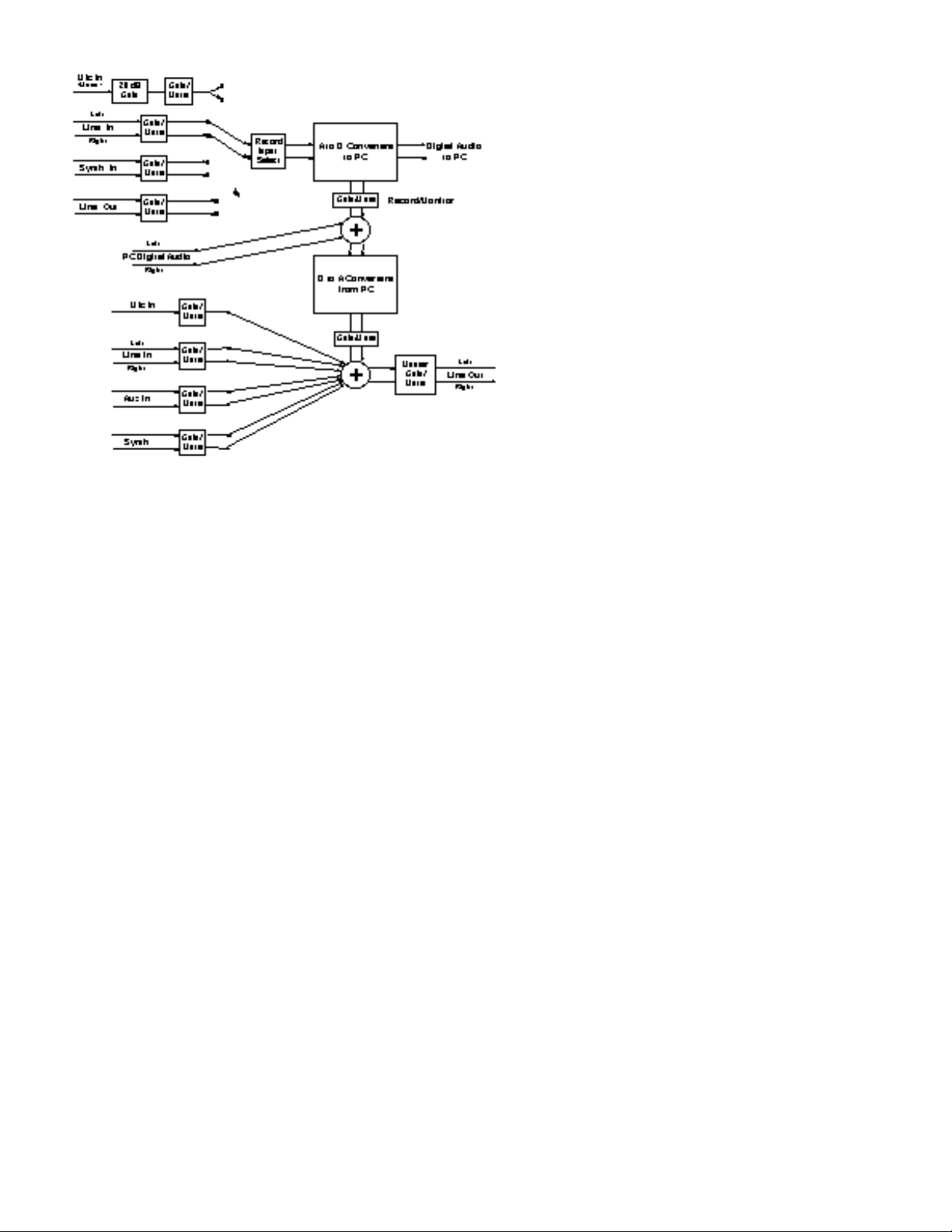
DMAN Block Diagram
11
Page 12

Hardware Installation
To mechanically install the DMAN do the following:
1. Turn off your computer.
2. Remove the cover and position the computer so that you can
easily access its ISA slots.
3. Select the ISA slot where you will install your DMAN card.
Make sure it is a 16 bit ISA slot. If you don't know what “16
bit ISA slot” means, check the owner’s manual for your
computer. A 16 bit slot consists of two in-line edgeconnectors instead of one.
4. Before removing the DMAN from its protective anti-static
bag, touch the metal power supply case of the computer in
order to dissipate any static electricity charge your body
may have accumulated. You might want to pick up a
grounding wrist strap (available from electronics stores like
Radio Shack) if you want to be doubly sure you aren't
carrying a static charge that could damage some of the chips
on the card.
5. Remove the metal bracket that covers the access hole on the
back of the computer. This bracket is usually fastened to the
computer with a single screw.
6. Position the DMAN card over the target ISA slot and fit the
card loosely over it with the DMAN card upright. Press the
card gently but firmly downward into the slot until the card
is completely and squarely seated in the slot. If the card
seems difficult to seat, a slight rocking motion may help.
7. Screw the DMAN's metal bracket down into the screw hole
on the back of your computer using the screw you removed
in step 5 above.
8. Place the cover back on your computer.
DMAN Connections (see Typical Setup Diagram below)
1. Connect the Line Out from the DMAN to the tape return jack
of your mixer, or to your amplifier, multimedia speakers, or
whatever else you may be using to amplify the sound. To
avoid a potential audio “pop”, it is a good idea to turn off
the amplifier or self-powered speakers before connecting to
Line Out.
2. Connect the tape send of your mixer, or Line Out of another
audio source, to the Line In jack of DMAN.
12
Page 13
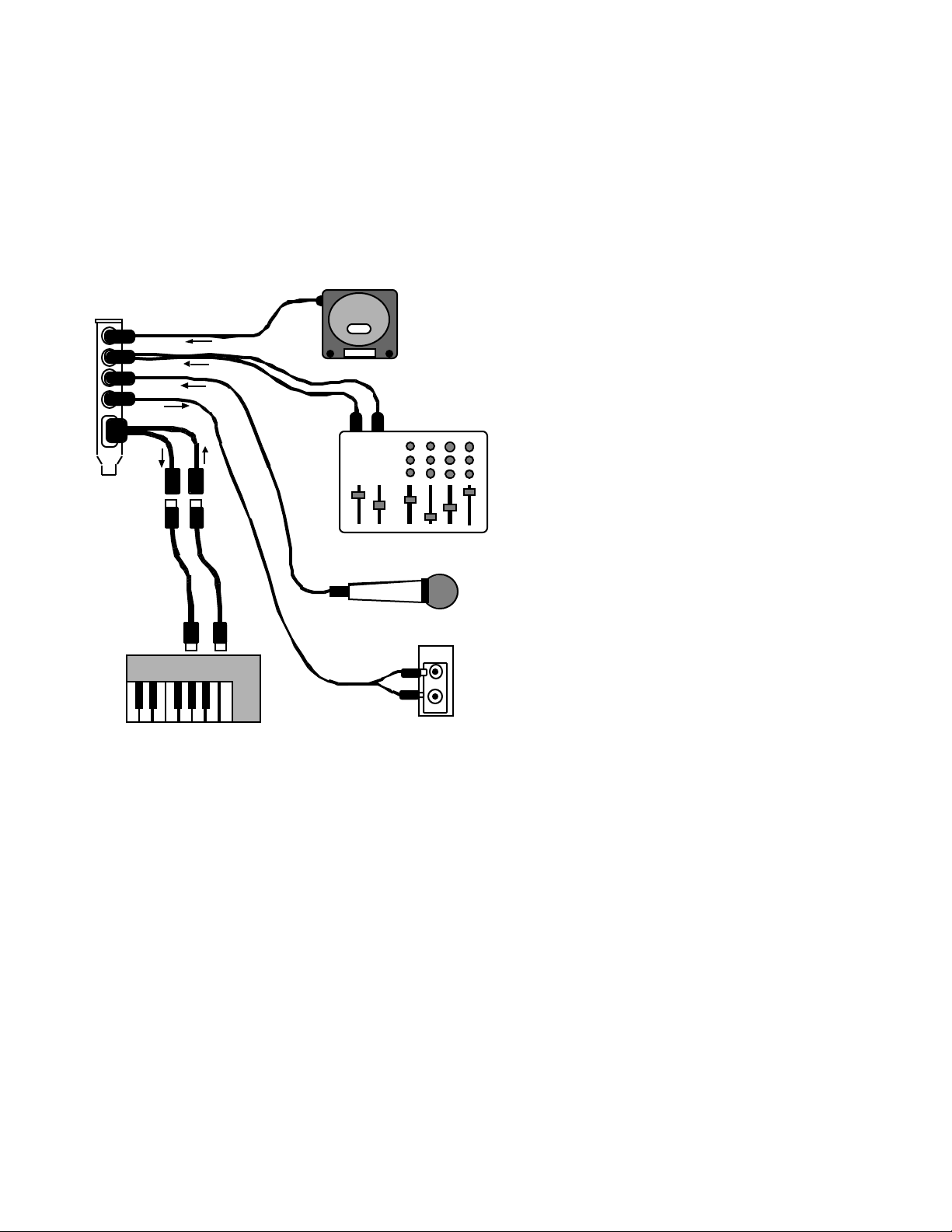
3. Connect the DMAN MIDI Interface Cable to the matching
DMAN connector at the back of the computer. Use the
thumb screws on the cable assembly to attach it securely to
the DMAN. If you don’t plan on using external MIDI, this
step is not necessary.
4. Attach any MIDI devices you have by connecting the MIDI
Out of your controller keyboard to the MIDI In of the
DMAN and MIDI Out connector of the DMAN to the MIDI
In on your keyboard or tone module. If you don’t plan on
using external MIDI, this step is not necessary.
5. Move your computer back to its original position. You may
now turn on your computer.
DMAN
DMAN Typical Setup
13
Page 14

Daughterboard Installation (optional)
DMAN provides a (26-pin header) daughterboard connector (see
diagram 2) for installation of an optional wavetable synthesis
daughterboard. The daughterboard interface is compliant with
most de facto industry-standard daughterboards. Adding this
daughterboard will give you built-in General MIDI (GM)
synthesis and enable you to combine (with the use of appropriate
software) MIDI sequenced sound with digitally recorded audio
produced by DMAN.
1. As above, turn off the computer, open the case, and make
sure you are grounded.
2. Locate the DMAN card in your computer.
3. Remove the bracket screw that is holding the DMAN in place.
4. Gently pull the DMAN straight out of the slot. If it is a tight
fit, once again use a slight rocking motion.
5. With DMAN in front of you, remove the daughterboard from
its anti-static bag and carefully align the header socket on the
daughterboard with the header pins on DMAN. Make sure
that the daughterboard is properly oriented so it is “inboard”
to the DMAN card. If any part of the daughterboard extends
beyond the DMAN PC board boundaries you have put the
board on backwards.
6. Following the instructions for Mechanical Installation,
reinstall DMAN in your computer.
Once the daughterboard is installed, it will take MIDI data from
the MPU401 section of DMAN. Choosing the DMAN MPU401
MIDI driver from your sequencing software (or MIDI Mapper)
will direct MIDI output to the daughterboard. The same MIDI
data will also appear at the DMAN MIDI Out connector.
14
Page 15
Windows 3.1x Software
Driver and Utilities Installation
Included with DMAN is a set of Windows 3.1x Drivers and
Applications diskettes which contain the Windows 3.1x drivers,
Windows 3.1x utility applications, and DOS software utilities.
The installation program on the first disk, SETUP.EXE, is run
from Windows 3.1x and installs all the Windows and DOS
software items. SETUP.EXE guides you through the installation
process and assists in configuring the sound driver’s parameters
to match the DMAN hardware configuration. To install the
Windows 3.1x drivers, Windows 3.1x utilities, and DOS utilities,
please follow these steps:
1. Insert the Windows 3.1x installation Disk 1 into drive A: (or
B:).
2. From within the Windows Program Manager, select the Run
option from the File pull-down menu.
3. When prompted, type the drive, directory and name of the
installation program to be run, for example:
4. Press the [ENTER] key or click on [OK]. The Setup program
will now uncompress any files required for installation.
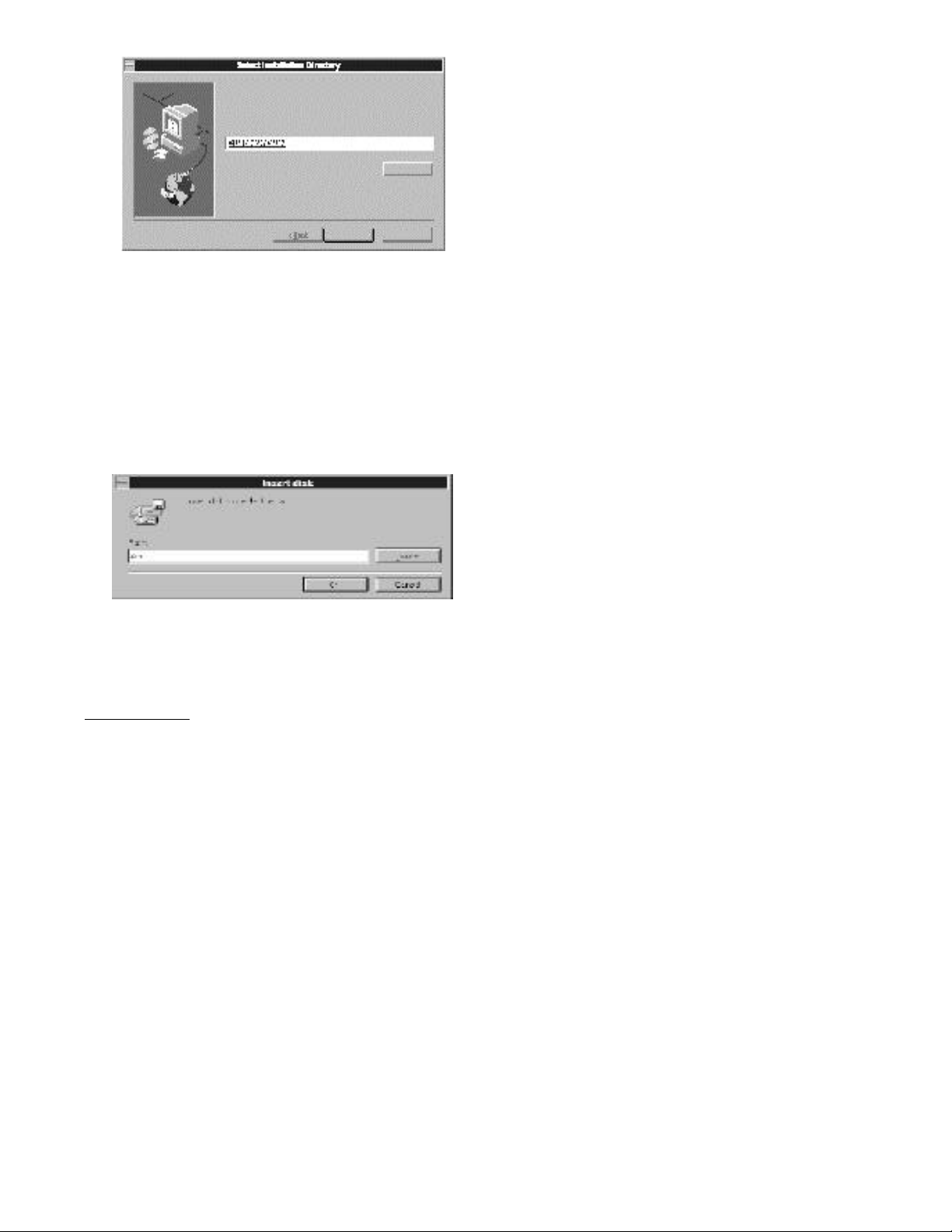
5. The DMAN files may be installed anywhere on your system.
When prompted for a destination directory for your files (see
diagram below), it is convenient to select the default of
C:\MIDIMAN\DMAN as the directory. Then press the
“Next>“ button.
15
Page 16
6. After you have selected the destination directory, the Setup
program begins to copy the DMAN software there. As each
software item is installed, its name is displayed. Also a
percentage is displayed, indicating the percentage completion
of the total installation.
7. Once all the files are installed from the first disk, Setup will
prompt you for Disk 2. Remove Disk 1, insert Disk 2 and
continue the installation by pressing the [ENTER] key. File
installation will continue until the Setup program is ready to
do its hardware configuration.
8. If your system does not have a PnP BIOS, you will be required
to set the DMAN Windows driver parameters manually.
Otherwise, if your system does have a PnP BIOS, skip this
step.
IMPORTANT:
result from attempting to use system resources (address
locations, IRQs and DMAs) already in use by other
hardware or software in the system. See the
“Troubleshooting” section for typical settings and
conflicts.
After all files are installed, the configuration dialog is
displayed for non-PnP systems. The default driver
Most sound card installation problems
16
Page 17

configuration settings depicted below are typical settings.
Yours may differ.
Configuration Screen
This dialog allows you to set the following parameters:
WSS Address - This is the base address of the Windows
Sound System controller (basically the controller for the D/A
and A/D converters). Changing this Windows WSS setting
will also change the related DOS WSS setting.
WSS Interrupt - This is the playback/capture IRQ used by
the WSS controller. Changing this setting will also change the
related DOS WSS setting.
WSS DMA Playback - This is the DMA channel used during
playback through the WSS D/A converter. In order to use
the full-duplex mode of operation (simultaneous
playback/record), this DMA channel must differ from the
WSS DMA capture channel. Changing this setting will also
change the related DOS WSS setting.
WSS DMA Capture - This is the DMA channel used during
capture (recording) through the WSS A/D converter. In
order to use the full-duplex mode of operation (simultaneous
playback and record), this DMA channel must differ from the
WSS DMA playback channel. Changing this setting will also
change the related DOS WSS setting.
MPU401 - This checkbox enables/disables the MPU401
compatible MIDI port on the DMAN. If desired, the MPU401
base address and IRQ may be changed later (see Windows
3.1x Driver Control Panel section).
17
Page 18

CD ROM - DMAN does not include a CD ROM interface.
This checkbox should be unchecked to disable CD ROM
support.
FM Synthesis - Although the driver may support an FM
synthesizer, there is no true FM synthesizer installed on the
DMAN board. Ignore this field.
Game Port - DMAN does not include a Game Port. This
checkbox should be unchecked to disable Game Port support.
SB Pro Address - DMAN emulates the digital audio portion
of a Sound Blaster Pro card (however, it lacks the FM
synthesizer present on SB Pro boards). You may have limited
luck playing digital audio through the DMAN from DOS
games supporting the SB Pro. This address applies to DOS
applications only.
9. Setup creates a new Program Manager Group, Midiman
Audio, which includes applications for controlling the
DMAN input and output audio mixes, recording/playing
DMAN inputs/outputs, and testing the card’s .WAV file
output.
10. In the background, Setup modifies your AUTOEXEC.BAT
and CONFIG.SYS files. It inserts the board initialization
utility CS4232C.EXE in CONFIG.SYS and also adds a
CS32MIX.EXE call to AUTOEXEC.BAT, which initializes the
DMAN audio mixer on bootup.
11. When Setup is complete, you are prompted to exit Windows
and reboot the system; Setup changes will take effect only
when the machine is rebooted and Windows is restarted.
Upon re-entering Windows, you should hear the “Tah Dah”
sound (or any other sound assigned to Windows Startup in the
Windows Control Panel) -- if not, turn to the
“Troubleshooting” section.
18
Page 19

Windows 3.1x Driver Control Panel
After installation, various Windows 3.1x driver parameters may
be altered via the Drivers applet of the Control Panel. To open the
Drivers applet, first open the Control Panel (usually in the
Windows 3.1x Main group), then open the Drivers applet from
within the Control Panel. The DMAN actually installs and uses
two separate drivers for its digital audio and MIDI. The "DMAN
Digital Audio / Mixer Driver” handles the digital audio
recording and playback, as well as the on-board audio mixer. The
"DMAN MPU 401” controls the MIDI port (MPU401 “UART”
mode compatible). A typical Drivers dialog is pictured below.
Windows 3.1x Drivers Applet
Audio Setup for Non-PnP Computers
If your computer has no PnP capability, or PnP is disabled, you
may modify the Windows 3.1x audio driver settings through the
Drivers Applet. First you must select the driver to set up by
highlighting “DMAN Digital Audio / Mixer Driver” entry, then
press the “Setup” button. The driver setup dialog will pop up.
Windows 3.1x Driver Setup - No PnP
19
Page 20

You now have the option of modifying the following resource
settings:
Duplex - Duplex modes determine whether DMAN can support
simultaneous playback and capture (recording). Half duplex
allows both playback or capture, but not at the same time.
Choose this option if your machine has low-performance or there
is only one DMA channel available for use. Full duplex is the
default for the Windows 3.1x drivers and provides simultaneous
capture and playback of audio data at the same sample rate.
Enhanced full duplex allows simultaneous capture and playback
with any combination of 11, 22.05, or 44.1 kHz files (requires
higher-performance CPUs).
I/O Address - This is the base address of the WSS controller
(basically the controller for the D/A and A/D converters).
Changing this Windows WSS setting will also change the related
DOS WSS setting.
DMA Channel - These are the DMA channels used for playback
and capture of digital audio. In half duplex mode, these channels
will be the same. For full and enhanced duplex modes, these
must be set to different values.
IRQ - This is the playback/capture IRQ used by the WSS
controller. Changing this setting will also change the related DOS
WSS setting.
Audio Setup for Computers with PnP
If your computer has a PnP BIOS and it is enabled, you may
modify some of the Windows 3.1x audio driver settings through
the Drivers Applet. First you must select the driver to set up by
highlighting the “DMAN Digital Audio / Mixer Driver ” entry,
then press the “Setup” button. The driver setup dialog below will
pop up.
20
Page 21

Windows 3.1x Driver Setup - With PnP
For PnP systems, the Base I/O address, IRQ, DMA playback and
capture channels are all determined through the PnP mechanism.
However, you may select the duplex mode from this dialog. For
more information regarding duplex modes, see the “Audio Setup
for Non-PnP Computers” section.
MIDI (MPU401 ) Setup
You may modify the Windows 3.1x MIDI driver settings through
the Drivers Applet. First you must select the driver to set up by
highlighting the “DMAN MPU 401” entry, then press the
“Setup” button. The driver setup dialog below will pop up.
Windows 3.1x MPU401 Driver Setup
You now have the option of modifying the following resource
settings:
Port - This sets the Base I/O Address of the MPU401 device.
21
Page 22

Interrupt - This sets the IRQ used by MPU401 MIDI input. The
typical IRQ is 2/9. Note that IRQ 6 is also assigned to the floppy
drive but in some cases may be shared with the MPU. Use IRQ 6
as a last resort.
Windows 3.1x Utility Applications
The DMAN Windows 3.1x setup program creates a Windows
Group called Midiman Audio which contains several sound
utilities. In this section we will discuss these applications
through which you control sound within your system:
• The Audio Input Control Panel
• The Audio Mixer Control Panel
• The Audio Transport
• The Sound Check Application
Audio Input Control Panel
The Audio Input control panel lets you control the source,
amplitude and quality of sound coming into your system.
Clicking on the Audio Input icon nested in the Midiman Audio
group will present you with the Audio Input Control Panel
shown here.
Audio Input Controls
Buttons and control features of the Audio Input Control Panel are
as follows:
About - The About button brings up a window describing the
applet and its version.
22
Page 23

Mixer - This button opens the Audio Mixer Control Panel
application.
Save - The Save button saves the current control settings to be
used as the initial settings when Windows is loaded.
OK - This button exits the Input Control Panel and keeps the
current device settings for the duration of the current Windows session.
Cancel - This button exits the Input Control Panel and restores
the device setting values which were present when it was opened.
Input Boost - The input boost slider control sets the gain on the
input audio signal to the Analog/Digital converter (this is
basically your recording level adjustment). The left and right
channels may be controlled separately or together by clicking on
the Gang box beneath the slider.
Volume Meter - The volume meter displays the amplitude of the
signal being controlled by the input boost slider control when the
VU On box beneath the meter is selected.
Input Selector - By clicking on any one of the four diamonds
below the Input Selector lets you select the source of the input
signal to be controlled (this selects the recording/capture source).
Only one source may be selected at a time. The four selections
are:
Synth - Selects the wavetable synthesizer as the input source
to the A/D, if the optional wavetable synthesizer is installed.
Line - Selects the Line Input jack as the input source to the
A/D.
Loop - Selects the internal loop back as the input source to the
A/D, feeding the output of the audio mixer back into the
A/D. This provides a mechanism for recording a mix of the
Mic, Synth, Line In, and Aux In signals simultaneously.
Mic - Selects the microphone as the input source to the A/D.
Boost - Clicking on the Boost box beneath the Mic diamond adds
20 dB additional gain to the microphone input. Use this only
with microphones that require it to maintain a good recording
level.
AGC - Clicking on the AGC box adds automatic gain control for
the microphone, adjusting its input gain automatically and
dynamically.
23
Page 24

Dither - Clicking on the Dither box toggles dither on/off for 8-bit
PCM audio. Dither improves 8-bit recordings.
IMPORTANT:
same time, you should first turn the “Vu On” checkbox off.
Next, turn the AGC on, then turn the Vu On back on.
Full Scale - The Full Scale window below the Dither box shows
the maximum allowable input level to the Analog/Digital
converter.
V rms/dB - Clicking on the V rms/dB button toggles the Full
Scale window between voltage and decibel modes.
To enable AGC and the Volume Meter at the
Audio Mixer Control Panel
The Audio Mixer control panel gives you control of the
amplitude and quality of the sound leaving your system.
Clicking on the Audio Mixer icon nested in the Midiman Audio
group will present you with the Audio Mixer control panel
shown below.
Buttons and control features of the Audio Mixer Control Panel:
About - The About button brings up a dialog window describing
this version of the audio mixer program.
Inputs - This button opens the Audio Input Control Panel
application.
Save - The Save button saves the current control settings to be
used as the initial settings when Windows is loaded.
OK - Exits the Audio Mixer control panel and keeps the current
device settings for the duration of the current Windows session.
24
Page 25

Cancel - This button exits the Input Control Panel and restores
the device setting values which were present when it was opened.
Master Volume - Controls the master volume for all audio
inputs. When the Gang box is checked, both left and right
channels are adjusted in tandem. When it is unchecked the left
and right channels may be independently adjusted. When the
Mute box is checked, all DMAN outputs are muted.
Rec Monitor - Sets the monitor level of the current source being
recorded; the monitor path mixes the input source back into the
output path. When the Mute box is checked, record monitoring is
disabled.
Wave Mix - The Wave Mix sliders control the left and right mix
for outgoing digital audio. When the Gang box is checked, both
left and right channels are adjusted in tandem. When it is
unchecked the left and right channels may be independently
adjusted. When the Mute box is checked, the DMAN digital
audio outputs are muted.
Synth Mix - The Synth Mix sliders control the left and right mix
for audio coming from an optional wavetable synthesizer
daughterboard. When the Gang box is checked, both left and
right channels are adjusted in tandem. When it is unchecked the
left and right channels may be independently adjusted. When the
Mute box is checked, the wavetable synthesizer is muted.
NOTE
: The inside of the computer is a very noisy place and
noise from other computer components may leak into any audio
sound card! For best signal-to-noise performance, mute or turn
down the mix levels of input devices not currently in use,
especially the “Synth Mix” if no optional wavetable synthesizer
daughterboard is installed on the DMAN.
Line Mix - The Line Mix sliders control the left and right mix for
audio present at the DMAN’s Line In jack. When the Gang box is
checked, both left and right channels are adjusted in tandem.
When it is unchecked the left and right channels may be
independently adjusted. When the Mute box is checked, the
audio from the DMAN Line In jack is muted.
Aux Mix - The Aux Mix sliders control the left and right mix for
audio present at the DMAN’s Aux In jack. When the Gang box is
checked, both left and right channels are adjusted in tandem.
When it is unchecked the left and right channels may be
25
Page 26

independently adjusted. When the Mute box is checked, the
audio from the DMAN Aux In jack is muted.
The Audio Transport
The Audio Transport application allows you to record and
playback digital audio files. Clicking on the Audio Transport icon
nested in the Midiman Audio group will present you with the
Audio Transport shown here. This section describes the buttons,
controls, and displays on the Audio Transport control panel.
The left-side buttons of the Audio Transport Control Panel are:
Open File - Selects a file to play, or opens a new audio file for
recording. It displays a Windows file open dialog box.
Access Audio Inputs - Opens the Audio Input Control panel.
Clipboard - Copies the current file to the Windows clipboard,
from which the audio file can be placed into other
applications.
User-defined - Goes to the application or utility of your
choice. See "The User-defined Audio Transport Button" later
in this chapter for instructions on how to define this button.
About - Displays the Audio Transport application
information.
26
Page 27

The Audio Transport control buttons are similar to those on a
tape recorder:
From left to right, these buttons are:
Play - Plays the selected audio file.
Stop - Stops playback of the selected audio file.
Pause - Pauses play.
Record - Starts recording the selected audio file.
Beginning - Goes to the beginning of the selected audio file.
Rewind - Goes backwards in the selected audio file until it
reaches the beginning of the file or until you stop the rewind.
Fast Forward - Goes forward in the selected audio file until it
reaches the end of the file or until you stop the fast forward.
End - Goes to the end of the selected audio file.
The display areas of the Audio Transport are shown below:
Audio Transport Displays
Their meanings are as follows (clockwise from upper right):
File Format Information - Displays the file audio format
including: sample rate, encoding, stereo/mono, number of
bits, and total length (in time) for the selected file.
Time Counter - Displays the current position (in time) in the
file.
Current File Display - After you select a file with the open file
command, the selected file is displayed in this window.
When a dot is displayed in the WP box, you can overwrite
the data in the file. When a dot is not displayed, the file is
27
Page 28

write protected and you cannot overwrite new data onto this
file. Click on this box to toggle between write protection
on/off.
Defining a New Audio File
When you select the open file button and specify a new audio file
by entering a new filename, the Select Tape Format dialog box
appears, allowing you to select the attributes of the new audio
file. This section describes the file attribute options. Refer to
“Select Tape Format Dialog Box” diagram below.
Select Tape Format Dialog Box
The formatting you select depends upon what you are recording
and your personal preferences. Higher quality recordings require
more disk space; lower quality recordings require less disk space.
If you are recording voice input, a lower quality recording
generally plays back with acceptable quality. If you are recording
high-fidelity input and desire the highest quality recording, select
the highest quality recording attributes that your disk storage
space can support.
With experience, you will learn what attributes best suit your
recording needs. Refer to “Audio Formats” section for the disk
space requirements of some typical recording formats. The
following are descriptions of each field in the Select Tape Format
dialog box:
Format - Selects the type of formatting to use during
recording.
PCM - PCM is uncompressed audio and provides the
best sound quality. It also consumes the most disk space.
28
Page 29

ADPCM - Provides 4:1 compression compared to 16-bit
PCM format. The compression means this format uses
less disk space but causes degradation in playback
quality.
m-Law - Provides 2:1 compression compared to PCM
format.
A-Law - Provides 2:1 compression compared to PCM
format.
Channels - Mono requires half the disk storage space as
stereo, and usually provides sufficient quality for voice
recordings.
Sample Rate (kHz) - Higher sample rates provide better
sound quality and require more disk storage space. Typical
sample rates are 11.025 kHz (for voice), 22.05 kHz (for
medium-fidelity), and 44.1 kHz (for high-fidelity CD quality
recording). 48 kHz is what some professional digital
recording systems use and offers the best fidelity of all,
although only a marginal amount better than using a 44.1
kHz sample rate.
Bits - Determines the resolution of the data. The higher the
resolution, the better the sound quality. Select 16-bit for
higher quality recording. Recording in 8-bit format can
sometimes cause distortion – or a hissing sound – during
playback. The Dither option in the Audio Input Control
panel may help reduce distortion caused by 8-bit recording.
The User-defined Audio Transport Button
The factory default application that runs when you press the
user-defined Audio Transport button is the Windows NOTEPAD.
To define some other application or utility to start up when you
click the user-defined Audio Transport button, follow these steps:
1. Open the CSACBAT1.INI file (located in \Windows) with
the DOS edit program, the Windows Notepad, or any
other text processing program.
2. Under the [APPLETS] category, insert the following lines:
UserAppPath=pathname
UserApp=filename
29
Page 30

Where pathname is the path (drive and directory) of the
application file, and filename is the name of the file to run.
3. Save and close the CSACBAT1.INI file.
The following is an example of the command lines in the
CSACBAT1.INI file that would cause Windows Write to start up
when you select the user-defined button:
[APPLETS]
UserAppPath=C:\Windows
UserApp=write.exe
Another good use of the button would be to run a .WAV file
editor.
Sound Check Application
The Sound Check application verifies proper operation of digital
audio playback. When executed, the application displays the
following panel and plays back a short digital audio music bite.
The test audio should be high-quality 16-bit stereo at 44.1 kHz
sampling frequency.
30
Page 31

Windows 95 Software
Driver Installation
Included with the DMAN is a Windows 95 diskette which
contains the Windows 95 drivers and DOS software utilities. To
install the Windows 95 drivers and DOS utilities, please follow
these steps:
1. Previous sound card installations can interfere with the
proper function of your new hardware. Consult the
documentation for your previous soundcard, and remove all
related driver software from the system prior to installing
your new hardware.
2. After installation of the DMAN hardware, boot your system
and start Windows 95. During the Windows 95 boot
procedure, new hardware (DMAN!) will be automatically
detected as shown here.
Windows 95 New Hardware Detection
3. Click OK to install the DMAN driver software from floppy.
4. When prompted for the Windows ‘95 Driver Disk, place it
into the A: drive and click OK.
Windows 95 Installation Prompt Dialog Box
31
Page 32

5. While installing the Windows 95 drivers, the installer
program also modifies your AUTOEXEC.BAT and
CONFIG.SYS files. It inserts the board initialization utility
CS4232C.EXE in CONFIG.SYS and also adds a CS32MIX.EXE
call to AUTOEXEC.BAT, which initializes the DMAN audio
mixer on bootup.
6. After completion of the driver installation, if your system has
no PnP or PnP is disabled, Windows 95 will require you to
restart Windows 95. If it does request a restart, remove the
floppy disk from drive A: and respond “yes.” The system
will restart and your DMAN is ready for play!
7. If PnP is enabled and installation completes without any
conflicts, the DMAN is ready for immediate use.
Windows 95 Driver Configuration
Windows 95 displays the DMAN driver status in the Device
Manager page of the System Properties dialog box. The Systems
Properties dialog is opened via the Windows 95 Start button.
Select ‘Settings, Control Panel’ to open the Windows 95 Control
Panel. Then select ‘System’ from the Control Panel to open the
System Properties dialog. Below is an example view of the
Device Manager device list.
System Properties - Device Manager
32
Page 33

This example shows the Midiman DMAN and Midiman
WINMAN 4x4/S (another Midiman product) entries in the
Windows 95 Device Manager device list. The DMAN is properly
installed with no conflicts. The WINMAN 4x4/S, however, is not
properly installed and this is indicated by the exclamation point
overlapping its icon. If an exclamation point is ever displayed for
the Midiman DMAN, you may go into the Device Manager and
manually make the adjustments necessary to get DMAN up and
running. This should rarely be required and usually is the result
of a non-PnP device being installed in the computer and
conflicting with various PnP devices.
By double-clicking on the DMAN item with the problem, you will
open up a properties sheet for that device. Selecting the Settings
and Resources pages from within the properties sheet will allow
you to manually adjust the DMAN resource settings.
NOTE:
devices, it is usually easier to readjust the resource settings of
the non-PnP device first. Windows 95 is only aware of the
resource settings of the installed PnP devices and has no
information available to it for adjusting the PnP devices around
the non-PnP devices. The exception to this is when a non-PnP
device has a true Windows 95 driver written for it; in that case
Windows 95 is aware of the non-PnP device’s resource
requirements.
When resolving conflicts between PnP and non-PnP
Windows 95 Mixer (WSS Mixer)
The DMAN audio playback and recording mixes are handled by
the Windows Sound System mixer that ships with Windows 95.
With the DMAN drivers properly installed, you should see a
loudspeaker icon on the Windows 95 taskbar. Double clicking
this loudspeaker icon accesses the WSS mixer. (Single clicks will
access the Master Out volume only). An alternate method for
opening the WSS mixer is to select ‘Programs, Accessories,
Multimedia, Volume Control’ via the Windows 95 Start button.
WSS Playback (Master Out) Mixer
The WSS playback mixer provides control over the output
volume levels, mute states, and balances for audio playback. The
Master Out (output) mixer is the default mixer when accessing
the volume control. To use the mixer, simply drag the desired
33
Page 34

controls with your mouse, or click on the Mute checkbox(es) to
mute device(s).
WSS Playback Mixer Window
WSS Properties Page
You may configure the playback window to display or not
display the various DMAN output devices. To do so, select
Options, Properties from the Master Out menu. The Properties
dialog box will then pop up, as shown below.
WSS Audio Mixer Properties Dialog Box
In this case the Playback mixer has been selected by default when
entering this window. The lower part of the window lists the
devices that may be displayed/controlled by the playback mixer.
If you do not want one or more of the devices to show up in the
mixer window, uncheck the box for that specific device. By the
way, PC Speaker does not apply to the DMAN and should be
unchecked. Then select OK.
34
Page 35

Note also that this dialog box is used to switch between playback
and recording displays. Under “Adjust Volume For:”, click on
the radio button of the mixer you desire. Click the Recording
button with the left mouse button to bring up the recording mixer.
Shown are the devices that are allowed as inputs to the recording
mixer. Again, unchecking a specific box will eliminate that
device from the input mixer window, known as the “Wave Input”
window. The “Wave Input” window is accessed when the “OK”
button is clicked.
WSS Recording (Wave Input) Mixer
The WSS recording mixer controls the volume and balance of
each DMAN input. One input at a time may be selected for
recording by checking the “Select” box below the desired device.
Here, the Line input has been chosen as the input device.
WSS Audio Input Mixer
The Mix Out input is a special input to the recording device; it is
used to record the combination of sounds present at the DMAN
Main Out. The relative mixes of the devices to be recorded is
determined by the WSS playback mixer settings. Mix Out is the
only way to record from the Aux In input to the DMAN board. It
is much more convenient to record the Line In since it has its own
record path into the DMAN.
The recording mixer pictured above has advanced controls
disabled. Advanced controls for the microphone may be enabled
by selecting ‘Options, Advanced Controls’ from the Wave Input
menu. The “Advanced” button now appears in the Microphone
35
Page 36

panel of the Wave Input mixer shown below. To access the
microphone’s advanced controls, click on the Advanced button.
WSS Audio Input Mixer w/ Advanced Controls
The figure below shows advanced options available for
microphone control. Although there are no Tone Controls on
DMAN, the microphone does have a 20 dB gain boost block that
may be enabled or disabled via this dialog box.
Advanced Controls for Mic
Windows Sound Recorder
Windows 95 provides a mechanism for audio playback and
recording using the Windows sound recorder. Select ‘Start,
Programs, Accessories, Multimedia, Sound Recorder’ to bring up the
sound recorder. make sure you select the input recording device
from the Wave Input control panel also. The recorder comes with
buttons to rewind, fast forward, play, stop and record.
36
Page 37

Win 95 Sound Recorder Applet
Additional features from the pull down menus include volume
and speed adjustment, echo and reverse effects, and audio file
insertion, mixing and sound quality conversion.
37
Page 38

DOS Software Utilities
The DMAN DOS software utilities are installed as a part of the
Windows 3.1x drivers and utilities, or the Windows 95 drivers.
IMPORTANT:
native DOS prompt, not from within Windows. For Windows
95 users, this means you should choose "Shutdown" from the
Windows 95 Start menu and then select "Restart in MS-DOS
mode" before running the DOS utilities. Windows 3.1x users
should simply exit Windows to DOS before running the DOS
utilities.
After installation of the Windows 3.1x drivers, you will find the
DOS software utilities in the directory selected during installation
(default is C:\MIDIMAN\DMAN). If installed with the
Windows 95 drivers, the DOS software utilities will reside in the
Windows 95 directory (C:\WINDOWS, on most systems).
The DOS utility programs must be run from the
DMAN Diagnostics Utility
As part of the DMAN Windows 3.1x or Windows 95 installation,
the diagnostic program CS32DIAG.EXE is installed on your hard
disk. This program runs a series of tests that you can use to
verify proper DMAN operation. Once at the DOS prompt, take
the following steps to run the DOS diagnostics program:
1. From the native DOS prompt, change to the subdirectory
containing CS32DIAG.EXE on your hard drive by using the
DOS "CD" (Change Directory) command. On a Windows 3.1x
system, this will usually be "CD C:\MIDIMAN\DMAN" if
you chose the default directory during installation. On a
Windows 95 system, this will be "CD C:\WINDOWS"
assuming that this is your Windows directory.
2. Type CS32DIAG and press the [ENTER] key. The DOS
diagnostic software will now execute.
Diagnostics Parameters Box
The info box that is now in the center of your diagnostic screen
displays hardware communication parameters for the DMA
Channel, IRQ, and I/O address. These parameters will be used by
the diagnostics program to check for proper
installation/operation of your DMAN.
38
Page 39

Diagnostics Test Box
Select the associated test button to test each option. The status of
each test is displayed to the left of each test button. A "fail" result
does not necessarily mean a sound card hardware failure. For
instance, the DMAN does not have the FM synth or joystick port
features which are included in the test. These tests will fail simply
because these features are not present. If the diagnostic program
accesses the hardware using the communication parameters
listed the test will be graded "Fail".
IMPORTANT:
and Joystick tests will fail because there is no joystick or FM
synth hardware on DMAN. These failures do not mean that
there is anything wrong with DMAN.
If you encounter any problems while running diagnostics or
during normal DOS operations at a later date, refer to the “DOS
Troubleshooting” section.
When running CS32DIAG.EXE, the FM Synth
DMAN DOS Mixer Utility
As part of the DMAN Windows 3.1x or Windows 95 installation,
the DOS sound mixer program CS32MIX.EXE is installed on your
hard disk. This program is a DOS graphical interface and
command line mixer utility that controls the same features as the
Windows sound mixer utility. The program may also be run as a
command line, with arguments, from the DOS prompt or in a
DOS batch file. In fact, the DMAN Windows software installation
will place a CS32MIX command in your AUTOEXEC.BAT file
that is run at boot time to initialize the mix levels of your DMAN.
To run the program as a graphical interface, type CS32DIAG and
press the [ENTER] key. The Mixer is then displayed in a
graphical form that is controlled by the keyboard or mouse (if the
mouse driver is installed.)
39
Page 40

DOS Sound Card Mixer
The easiest way to control the sound parameters is with a mouse.
Simply drag the solid black “sliders” to their desired positions
and click on the Line, Mic, and Aux “checkboxes” to select the
input source. The various parameters may also be controlled by
using hot keys (Alt + highlighted letter), and the tab and arrow
keys to increase/decrease left/right channels for each input. Tab
to the Gang option and press the spacebar to toggle off
(unchecked); allowing the left and right channels to be adjusted
separately. The Default button will reset inputs to the system
default settings. The Save button will save the current mixer
settings as the default system startup values. Settings are
retained until the next time you change and save the settings. For
temporary changes, the OK button will retain current changes for
the duration of the current Windows session.
To use the DOS Mixer in command line mode, enter CS32MIX
followed by one or more command line flags. Typing CS32MIX
/? at the DOS prompt, followed by the [Enter] key, will display
the command line flags available to you. The following options
are available:
/M= (left), (right) <0-15> ; Master Volume
/W= (left), (right) <0-15> ; Wave Volume
/L= (left), (right) <0-15> ; Line Volume
/X= (mono) <0-7> ; Mic Volume
/F= (left), (right) <0-15> ; Synth Volume
/C= (left), (right) <0-15> ; Aux Volume
/I= (L, X or C) ; Input Select =Line, Mic or Aux
/D ; Use Default values
/S ; Show mixer settings
For example, to change the master volume by the same amount
for both channels enter CS32MIX /M=8,8 or CS32MIX /M=8 at
the DOS prompt.
40
Page 41

DMAN with 3rd Party Applications
Sooner or later you will want to use DMAN with some of the
advanced 3rd party applications currently available. It is with
these applications that the DMAN becomes a true multi-track
digital audio recording tool. Although there are various setup
parameters built into Windows for selecting audio quality, etc.,
the 3rd party applications usually work around those settings.
IMPORTANT:
bypasses the general Windows settings and instead has its own
means of setting up the DMAN record/playback sample rate,
format, full- and half-duplex settings.
For example, you often select the sampling rate (22 kHz, 44.1
kHz, and even 48 kHz on some products) and format (16-bit
stereo, 8-bit mono, etc.) directly from within that application.
However, you usually select the recording source (Mic, Line In,
Synth In, Mix In) from the mixer application supplied with
Windows 95 (or the input mixer application we install in
Windows 3.1).
In addition, the application may require you to explicitly select
the audio device by name for the application to use. This also
goes for MIDI applications -- they will require you to select the
DMAN MPU401 device as the MIDI input/output device.
Please consult the user’s manual that shipped with your 3rd party
application for more specific information regarding its audio and
MIDI configuration and setup.
3rd party digital audio recording software often
41
Page 42

Audio Formats
DMAN supports recording and playback in many audio formats.
When selecting an audio format, you are usually trading off
sound quality versus the amount of disk space the recorded
audio will consume. In general, sound quality increases as the
Sample Rate increases, as the number of bits used increases, as
stereo is used instead of mono, and when the audio is not
compressed (i.e., its format is PCM not ADPCM or A-Law).
Sample Rate is the parameter most directly related to frequency
response and should be chosen carefully (unless you have
unlimited disk space available!). Choose a sample rate that is at
least twice the frequency (this is called the Nyquist value) of the
highest audio frequencies you want to record. For example, if
your source material has a frequency range of 30 Hz to 10 kHz,
you can record at a sample rate of 22 kHz. Increasing to 44.1 kHz
is unlikely to improve the audio quality and it will take twice as
much disk space to store the file. Below is a table of commonly
used audio formats and the applications they are best suited for.
Hard-Disk Space Requirements for Typical Audio Formats
Format
PCM Stereo 48 kHz 16 11 MB High-fidelity music -
PCM Stereo 44.1 kHz 16 10 MB High-fidelity music -
PCM Mono 44.1 kHz 16 5 MB High-fidelity music -
ADPCM Stereo 44.1 kHz 4 2.5 MB Music
ADPCM Stereo 11 kHz 4 660 KB Voice (mono is
ADPCM Mono 11 kHz 4 330 KB Voice
Channels
Sample
Rate
Bits
Disk Space
per Minute
Typical Use
Pro quality
CD quality
Mono CD quality
recommended)
Disk Space Requirements for Typical Recording Formats
42
Page 43

Troubleshooting
This section addresses potential problems that can occur in all
operating system environments, with emphasis on hardware
troubleshooting. Within the PC environment there is a limited
number of hardware resources (addresses, IRQs, and DMA
channels) available for use. Since audio cards require many
resources, most audio card installation problems arise from
improperly set IRQ and DMA values. The tables below list the
IRQ and DMA channel assignments normally used in the PC
environment. When you experience problems that indicate a
resource conflict, you can compare the IRQ and DMA channels
shown in the tables below with your current parameters, as listed
in the Configuration screen.
Typical IRQ Assignments
Interrupt IBM PC Assigns This Interrupt To:
IRQ2/9 Available
IRQ3 COM2: Second Serial Port
IRQ4 COM1: First Serial Port
IRQ5 LPT2: Second Parallel Printer Port, usually
IRQ6 Floppy Disk Controller
IRQ7 LPT1: 1st Parallel Printer Port, usually available
IRQ8 Real Time Clock
IRQ10 Available
IRQ11 Available
IRQ12 Pointing Device (PS/2 or bus type Mouse)
IRQ13 Math Co-processor
IRQ14 Hard Disk Controller
IRQ15 Second Hard Disk Controller, usually available
available
43
Page 44

Typical DMA Assignments
DMA
IBM PC Assigns This Channel To:
Channel
0 Available
1 Available
2 Floppy Disk
3 Available
4 (16-bit) Hard Disk -- DMAN unable to use this channel.
5 (16-bit) DMAN unable to use this channel.
6 (16-bit) DMAN unable to use this channel.
7 (16-bit) DMAN unable to use this channel.
Problem: No Sound.
Possible Cause 1: Volume control adjustment. There are two volume
controls that affect the sound level of each audio device (Mix Level and
Master Volume) -- make sure neither is set too low.
Possible Cause 2: Improper connections of the audio accessories. Verify
that the Line Out is properly connected to a headset or external
mixer/amplifier. Also check your audio source and verify that its levels
are turned up and it is properly connected to DMAN.
Possible Cause 3: There is a resource conflict with one or more other
devices in your computer. This is more evident during the recording
and playback of digital audio rather than the Line In, Mic In, and Aux In.
Check the DMAN configuration (address, IRQ, and DMA channel(s))
against those of the other devices on your computer. If necessary,
change the settings for the one or more of the devices.
Problem: Cannot Play/Cannot Capture Digital Audio.
Possible Cause: DMA Channel conflict. Check that no other devices in
your system are attempting to use the same DMA channel(s) as DMAN.
Change DMA channels. You might also switch to half duplex mode,
which requires a single DMA channel. If the condition subsides you will
know which DMA channel was in conflict.
Problem: No visual activity on Audio Input volume (VU) meter.
Possible Cause 1: Wrong input (mic, line, synth, loop) selected.
Possible Cause 2: DMA Channel conflict. See above.
Problem: Repetitious Sound.
Possible Cause: Wrong IRQ. Often this will result in a small segment of
sound (0.5 to 1 second) repeating itself over and over, sometimes
completely locking up the computer. If this problem occurs in Windows,
open the driver configuration dialog box and set the IRQ to match the
current DMAN setting. If this problem is in DOS, reconfigure the IRQ in
the DOS application itself to match that of DMAN.
44
Page 45

DOS Troubleshooting
When you run DMAN DOS-based diagnostics application, each
test passes or fails on the basis of meeting two criteria. Each test
checks that DMAN can be contacted at the parameter in question,
and also pauses for a period of time to ensure that no IRQ, DMA
request, etc. is initiated by a device other than DMAN. Failing to
reach DMAN or detecting the signal from another device will
cause the test to fail.
To fix communication conflicts, you may need to edit the
initialization file CS4232.INI which resides in the same directory
as the other DMAN DOS applications. This is usually
C:\MIDIMAN\DMAN if you chose the default during
installation. CS4232.INI is a text file that may be edited manually
using a text editor such as DOS’s EDIT.COM or Windows’
NOTEPAD.EXE. If you change any parameters in the CS4232.INI
file you will need to run CS4232C.EXE located in that same
directory. Running CS4232C.EXE will reconfigure DMAN to the
changed settings.
IMPORTANT
systems. Systems with PnP ignore the CS4232.INI file and
automatically configure the devices in the system to what it
believes are available addresses, IRQs, and DMA channels. In
this PnP case, you will have better luck modifying the settings
of the non-PnP (older ISA cards) devices to not clash with the
DMAN settings.
The following settings may be edited in the CS4232.INI file:
SndBlstr Port Address: If the SndBlstr (Sound Blaster) test fails,
you may have a port address conflict. Usually this will only
happen if another Sound Blaster compatible card is installed in
the computer. Change the SB Port Address setting indicated by
the "SbIO=" line in the [PNP] section. Set it to either 220, 230 or
240.
SndBlstr Interrupt: If the SndBlstr (Sound Blaster) test fails, you
may have an interrupt (IRQ) conflict. Change the line "WSSInt="
in the [PNP] section in the CS4232.INI file. Set it to 5,7,9,11,12 or
15.
SndBlstr DMA Channel Conflict: If the SndBlstr (Sound Blaster)
fails, you may have a DMA playback channel conflict. Change
the DMA playback channel setting in the CS4232.INI file. This is
: The CS4232.INI file only affects non-PnP
45
Page 46

specified in the "WssDmaPlay=" line of the [PNP] section.
Possible settings are 0,1,3.
NOTE
: Sound Blaster and WSS share the same interrupt and
playback DMA channel. Therefore, a conflict error with SB
will also affect WSS configuration settings.
CODEC Port Address: If the CODEC test fails, you may have a
port address conflict. Change the I/O Port Address that the
application is using to communicate with the sound card by
changing the "WssIO=" line in the CS4232.INI file. Set it to 534,
608, E84 or F44.
CODEC Interrupt: If the CODEC test fails, you may have an
interrupt (IRQ) conflict. Change the interrupt setting used to
communicate with your sound card. The interrupt is set by the
line "WssInt=" in the CS4232.INI file. Set it to 5,7,9,11,12 or 15.
CODEC DMA Channel Conflict: If the CODEC test fails, you
may have a DMA capture or playback channel conflict. Change
the DMA Capture or Playback Channel settings in the CS4232.INI
file, which are specified in the "WssDmaCapture=" and
"WssDmaPlay=" lines of the [PNP] section. Possible settings are
0,1 and 3. Set both to the same value for half-duplex operation
and to different values for full-duplex.
MPU401 Port Address: If the MPU401 test fails, you may have a
port address conflict. Change the I/O Port Address that the
application is using to communicate with DMAN by changing the
"MPU401IO=" line in the CS4232.INI file. Set it to 300, 320, 332,
338, 340 or 360. This value may have to be adjusted to match the
acceptable values in the Windows 3.1x MPU401 driver.
MPU401 Interrupt: If the MPU401 test fails, you may have an
interrupt (IRQ) conflict. Change the interrupt setting used to
communicate with the MPU401 port. The interrupt is set by the
line "MPU401Int=" in the CS4232.INI file. Set it to 5,7,9 or 11.
46
Page 47

Windows 3.1x Troubleshooting
Problem: When starting Windows, you receive error messages such as
“VSNDSYS.386 Not Found” or “CS32BA11.DRV Not Loaded”.
Possible Cause 1: Your DMAN Windows driver is not completely
installed or has been removed. Install/reinstall the DMAN audio drivers
(see Windows 3.1x Software section).
Possible Cause 2: You are experiencing a driver or resource conflict. If
you install the driver for some other sound card instead of the DMAN
Windows drivers, or if more than one sound driver (e.g., Creative Labs
Sound Blaster 1.0/1.5 or Media Vision Thunder Board) is loaded in
Windows, a conflict may arise. To solve this problem, you should
remove all unnecessary drivers, and install/reinstall the DMAN audio
drivers (see Windows 3.1x Software section).
Possible Cause 3: Your Windows 3.1x driver settings do not match
those of the DMAN hardware and must be changed to match those of the
hardware.
Problem: The Windows Media Player does not play MIDI through the
DMAN MIDI port or to the optional wavetable synthesizer
daughterboard.
Possible Cause 1: The Windows MIDI Mapper is not configured to
drive the DMAN MIDI (MPU401 ) port. Open the Windows Control
Panel, then open the MIDI Mapper. Select the setup named “DMAN
MIDI Port”.
Possible Cause 2: The DMAN MIDI driver is not properly installed.
The MIDI Mapper icon does not appear in the Windows Control Panel,
then the DMAN MIDI driver is probably not installed at all.
Install/reinstall all DMAN audio drivers (see Windows 3.1x Software
section).
Possible Cause 3: The DMAN MIDI (MPU401 ) driver settings do not
match those of the DMAN hardware and must be changed to match
those of the hardware.
Problem: A 3rd party Windows digital audio program does not play or
record to/from DMAN.
Possible Cause 1: The DMAN Audio driver is not properly installed.
Install/reinstall all DMAN audio drivers (see Windows 3.1x Software
section).
Possible Cause 2: You have not selected the DMAN audio driver from
your application. Many 3rd party applications require you to select a
specific driver (because there can be more than one in an advanced
system) for use with the application. Select the driver named “DMAN
Audio Device Driver” as your audio driver. The manner in which this
selection is made is dependent on the application (each one is a little
different).
47
Page 48

Problem: A 3rd party Windows MIDI program does not play or record
MIDI to/from DMAN.
Possible Cause 1: You have not installed an optional wavetable
synthesizer daughterboard or you do not have a MIDI keyboard or
sound module attached to the MIDI interface adapter cable.
Possible Cause 2: The DMAN MIDI driver is not properly installed.
Install/reinstall all DMAN audio drivers (see Windows 3.1x Software
section).
Possible Cause 3: You have not selected the DMAN MIDI driver from
your application. Many 3rd party applications require you to select a
specific MIDI driver (because there can be more than one in an advanced
system) for use with the application. Select the driver named “Midiman
DMAN MPU401” as your MIDI driver. The manner in which this
selection is made is dependent on the application (each one is a little
different).
48
Page 49

Windows 95 Troubleshooting
If the installation has not been successful or if Windows ‘95
cannot resolve one or more hardware resource conflicts, the
devices affected will be highlighted (note the exclamation mark in
the icon) in the Device Manager page as discussed in the “System
Properties - Device Manager” section of this manual. In theory,
this should never happen in a fully-compliant, Plug & Play (PnP)
system. However, there are a couple of circumstances in which it
may:
1. There are not enough IRQs and/or DMA channels available
in the system to support all the installed hardware.
2. Some legacy devices (older ISA cards that are not PnP
compliant) may exist in the system. Because the PnP BIOS
has difficulty in identifying and configuring these legacy
devices, it cannot adequately configure and resolve conflicts
between the PnP and non-PnP devices.
In (1) above, you usually have no choice but to remove one or
more cards from the system. DMAN offers the PnP system some
alternatives when resources are low. One is to run the digital
audio in half-duplex mode instead of full-duplex. This reduces
the DMAN DMA channel requirements from two channels to
one. Also, the MPU401 device IRQ may be disabled. In this case
you will lose your ability to receive MIDI input, but you may still
use the MIDI output for playback.
In (2) above, you will need to do some detective work to find out
where the conflicts are taking place, then modify the driver
settings for the conflicting device. Double-clicking on the
highlighted device will give more details as to the problem
encountered. See the section on Windows 95 Driver
Configuration for more information on this topic.
Problem: Can open the Windows 95 WSS record mixer but can’t find the
playback mixer or vice-versa.
Possible Cause: Change between the two by selecting “Options,
Properties” from the mixer’s menu. See the section on Windows 95
Mixer for more specific information.
Problem: A 3rd party Windows digital audio program does not play or
record to/from the DMAN.
Possible Cause 1: The DMAN Audio driver is not properly installed.
Install/reinstall all DMAN audio drivers (see Windows 95 Software
section).
Possible Cause 2: You have not selected the DMAN audio driver from
your application. Many 3rd party applications require you to select a
49
Page 50

specific driver (because there can be more than one in an advanced
system) for use with the application. Select the driver named “DMAN
Audio Device Driver” as your audio driver. The manner in which this
selection is made is dependent on the application (each one is a little
different).
Problem: A 3rd party Windows MIDI program does not play or record
MIDI to/DMAN.
Possible Cause 1: You have not installed an optional wavetable
synthesizer daughterboard, or you do not have a MIDI keyboard or
sound module attached to the MIDI interface adapter cable.
Possible Cause 2: The DMAN MIDI driver is not properly installed.
Install/reinstall all DMAN audio drivers (see Windows 95 Software
section).
Possible Cause 3: You have not selected the DMAN MIDI driver from
your application. Many 3rd party applications require you to select a
specific MIDI driver (because there can be more than one in an advanced
system) for use with the application. Select the driver named “Midiman
DMAN MPU401 ” as your MIDI driver. The manner in which this
selection is made is dependent on the application (each one is a little
different).
Problem: I’m getting some pops and clicks in my audio recording
Possible Solution: Many accelerated graphics cards use enough system
resources that the recording buffer can’t keep up with demand. This can
cause clicks in the recording. This is a software level problem, but can
often be solved by turning off the graphics acceleration features of the
graphics card. In Windows 95, this is accessed from Settings/Control
Panel/System/Performance/Graphics (see figures below).
Put Figure POPS1.TIFF here
Put Figure POPS2.TIFF here
50
Page 51

Appendix - Technical Specs
Channel Volume Controls
Over a range of 64 dB:
Stereo Master Volume: 64 steps range
Stereo Aux In: 32 steps range
Stereo Line in: 32 steps range
Stereo Digital Audio: 64 steps range
Stereo Synth In: 32 steps range
Mono Mic-in: 32 steps range
External Audio Inputs
Mic Input Level: 10 mV to 200 mV p-p max
Line Input Level:
Aux Input Level:
External Audio Outputs
Output Type: Combined line/headphone out
Output Level: Line output/headphone: 1.5 V rms
Load Impedance: Line output: 32 ohms
Frequency Response: 20 Hz - 20 kHz (± 3 dB)
Dynamic Range: 80 dB, typical 85 dB
Signal to Noise Ratio
(SNR):
Total Harmonic
Distortion (THD):
Channel Separation: > 65 dB
Impedance: 600k ohms or 20k ohms
Power supplied: 2.5V at 1 ma
Impedance:
Impedance:
Line output: >80 dB
Line output: <0.015% @ 1 kHz
2 V rms max
10k ohms
2 V rms max
10k ohms
Board Configuration
IRQ: 5,7,9,11,12,15
DMA: 0, 1, 3
CODEC Base Address: 120H - 3FCH in 4-byte increments
MPU401 Base Address: 330H - 360H in 8-byte increments
51
Page 52

Limited Lifetime Warranty
MIDIMAN warrants that this product is free of defects in materials and
workmanship under normal use so long as the product is: owned by the original
purchaser; the original purchaser has proof of purchase from an authorized
MIDIMAN dealer; and the purchaser has registered his/her ownership of the
product by sending in the completed warranty card.
This warranty explicitly excludes power supplies any included cables which may
become defective as a result of normal wear and tear.
In the event that MIDIMAN receives written notice of defects in materials or
workmanship from such an original purchaser, MIDIMAN will either replace the
product, repair the product, or refund the purchase price at its option. In the event
any repair is required, shipment to and from MIDIMAN and a nominal handling
charge shall be born by the purchaser. In the event that repair is required, a
Return Authorization number must be obtained from MIDIMAN. After this
number is obtained, the unit should be shipped back to MIDIMAN in a protective
package with a description of the problem and the Return Authorization clearly
written on the package.
In the event that MIDIMAN determines that the product requires repair because
of user misuse or regular wear, it will assess a fair repair or replacement fee. The
customer will have the option to pay this fee and have the unit repaired and
returned, or not pay this fee and have the unit returned unrepaired.
The remedy for breach of this limited warranty shall not include any other
damages. MIDIMAN will not be liable for consequential, special, indirect, or
similar damages or claims including loss of profit or any other commercial
damage, even if its agents have been advised of the possibility of such damages,
and in no event will MIDIMAN's liability for any damages to the purchaser or any
other person exceed the price paid for the product, regardless of any form of the
claim. MIDIMAN specifically disclaims all other warranties, expressed or implied.
Specifically, MIDIMAN makes no warranty that the product is fit for any
particular purpose.
This warranty shall be construed, interpreted, and governed by the laws of the
state of California. If any provision of this warranty is found void, invalid or
unenforceable, it will not affect the validity of the balance of the warranty, which
shall remain valid and enforceable according to its terms. In the event any remedy
hereunder is determined to have failed of its essential purpose, all limitations of
liability and exclusion of damages set forth herein shall remain in full force and
effect.
52
 Loading...