

Page 1

Table of Contents
FCC Class B and CE Compliance ................................................ 2
Features............................................................................................. 3
Overview.......................................................................................... 4
Installation........................................................................................ 5
Panels - Fig. 1 ................................................................................... 6
Panel Description ............................................................................ 7
Front Panel ........................................................................... 7
Back Panel ........................................................................... 8
Operation ........................................................................................ 9
Creating a New Patch......................................................... 9
Editing Existing Patch ...................................................... 10
Editing MIDI Receive Channel........................................ 11
Turning MIDI Thru On and Off ...................................... 11
Bulk Data Dumps via MIDI............................................. 12
Appendix 1 - Diagnostic Test ..................................................... 12
Appendix 2 - MIDI Implementation ......................................... 15
Appendix 3 - Mac “Panel” Software ......................................... 16
Appendix 4 - PC “Panel” Software............................................ 18
Lifetime Limited Warranty ...........................................................19
Digipatch 12x6
™
MANUAL
version: Digi-061799
1
Page 2

2
Lifetime Limited Warranty .......................................................... 19
READ THIS ! ... READ THIS ! ....
Included with DigiPatch 12x6
™ are factory diskettes
containing Mac and PC DigiPatch applications. Either
of these programs can be installed on your computer in
the conventional manner .
FCC Class B and CE Compliance
WARNING: This equipment has been tested and found to comply with the
limits for a CLASS B digital device, pursuant to Part 15 of the FCC Rules.
These limits are designed to provide reasonable protection against harmful
interference in a residential installation. This equipment generates, uses and
can radiate radio frequency energy and, if not installed and used in accordance with the instructions contained in this manual, may cause harmful
interference to radio and television communications. However, there is no
guarantee that interference will not occur in a particular installation.
If this equipment does cause harmful interference to radio or television
reception, which can be determined by turning the equipment off and on,
the user is encouraged to try to correct the interference by one or more of
the following measures: 1) reorient or relocate the receiving antenna; 2)
increase the separation between the equipment and the receiver; 3) connect
the equipment into an outlet on a circuit different from that of the receiver;
4) consult the dealer or an experienced audio television technician.
NOTE: Connecting this device to peripheral devices that do not
comply with CLASS B requirements or using an unshielded
peripheral data cable could also result in harmful interference to
radio or television reception.
The user is cautioned that any changes or modifications not expressly
approved by the party responsible for compliance could void the user’s
authority to operate this equipment.
To ensure that the use of this product does not contribute to interference, it
Page 3

3
is necessary to use shielded I/O cables.
This product also complies with European CE requirements.
Features
The DigiPatch 12x6 is an automated patchbay which routes digital
audio connections between gear equipped with S/PDIF and Adat*
compatible digital audio connectors. The DigiPatch 12x6 has the following features:
•Twelve completely independent sources: six coaxial (RCA) inputs
and six optical (EIAJ) inputs.
• Six targets: one coaxial output and one optical output per target.
• 50 non-volatile internal patch configurations can be programmed,
stored, and recalled at any later time.
• All connections are “format neutral” and can be used for S/PDIF
or Adat.
•Works with all digital audio format converters and swiss-army
knives.
• Performs simple coaxial-to-optical and optical-to-coaxial transla-
tions for S/PDIF signals.
• Built-in MIDI thru function for easy hook-up to any existing MIDI
setup.
• Multiple DigiPatch 2patchbays can be cascaded together for even
more ins and outs.
•DigiPatch can be programmed from the front panel, or controlled
remotely from a computer using DigiPatch Panel™ software for
Mac or PC included with the unit.
• The perfect companion for synthesizers, HD recorders, MDMs,
digital mixers, digital mic preamps, stand alone ADCs and DACs,
effects processors, etc.
• Single height, full rack mount enclosure.
• Rugged all steel construction.
Page 4

4
* Adat is a registered trademark of Alesis Corporation
Overview
Thanks for choosing a DigiPatch to automate your digital audio
routings. Like the name says, the DigiPatch 12 x 6 is a twelve by six
digital audio patchbay. It has twelve completely independent inputs
called sources, and six PAIRS of outputs called targets.
Patchbay connections are made from the perspective of the target. In
other words, you first choose which target to edit, and then choose
the source for that target. Once you have selected the sources for the
desired targets you can store this setup into a program and recall it
later.
If you’re already using digital audio gear you’ll find the DigiPatch to
be very easy to operate. If you are new to digital audio (and digital
audio connections) you’re facing a small learning curve. The most
important rule to remember is this:
Please Note: The DigiPatch is a simple switching matrix. It routes
digital ones and zeros from one connector to another. It can be
used for optical-to-coaxial and coaxial-to-optical conversions. It
does not “decode” or “listen to” the digital audio signals. In particular, it doesn’t know the difference between an S/PDIF signal
and an Adat signal. It will not prevent you from making nonsensi-
Page 5

5
cal connections between the two formats.
Installation
Your DigiPatch box should contain this manual, the power transformer, and the unit itself. Save all packing materials in case you
should ever want to ship the unit.
The DigiPatch takes up one space in a standard 19” equipment rack.
Install it as you would any other piece of gear, but keep in mind that
digital audio cable lengths should be as short as possible.
There are no special rules for deciding which of the DigiPatch’s connectors to use with the various devices in your setup. You should
keep in mind however, that a DigiPatch target is a PAIR of output
connectors. This means that any signal that is transmitted from optical output N is also transmitted from coaxial output N. Even Adat
signals!
The most straightforward approach is to keep a one-to-one relationship between devices and I/O numbers. For example: To hook up
an Adat, connect optical input 1 on the DigiPatch to the Adat’s digital out, then connect optical output 1 on the DigiPatch to the Adat’s
Page 6
6
digital in.
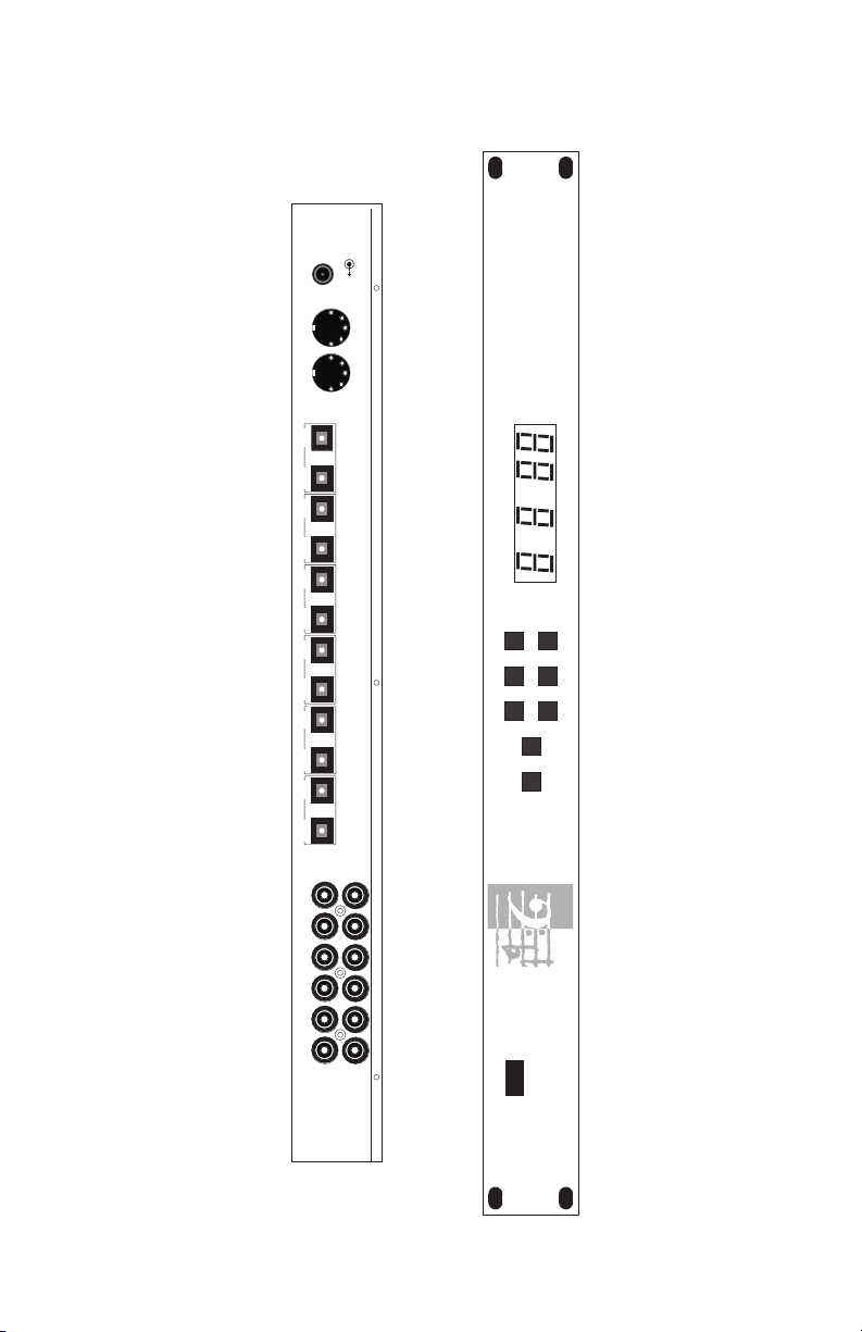
l
▲
9VDC
IN OUT
MIDI OPTICAL
PROGRAM TARGET SOURCE
PROGRAM TARGET SOURCE
▼▼▼
▲
▲▲
MIDI STORE
IN6 1 2 3 4 5 6OUT6OUT5IN5OUT4IN4OUT3IN3OUT2IN2OUT1IN1
DigiPatch 12x6
DIGITAL AUDIO PATCHBAY
™
COAXIAL
IN
OUT
POWER
Page 7

7
Panels - Fig. 1
Panel Description
Front Panel
1. Program indicator: This normally displays the current program
number, but when the MIDI button is held it will display the
midi channel.
2. Target indicator: This normally displays the current target num-
ber, but when the MIDI button is held it will display the midi
thru ON / OFF status.
3. Source indicator: This displays the current source number.
When the MIDI button is held it will go blank.
4. Program Inc / Dec buttons: This pair of buttons is normally used
to select a new program, but when the MIDI button is held they
are used to select the midi channel.
5. Target Inc / Dec buttons: This pair of buttons is normally used to
select the current target, but when the MIDI button is held they
are used to select the midi thru ON / OFF status.
6. Source Inc / Dec buttons: This pair of buttons is used to select
the current source, but when the MIDI button is held they do
nothing.
7. MIDI button: This button behaves like a dead-man switch.
When you press and hold it the indicators and buttons perform
their alternative midi functions.
8. Store button: When you press this button the first time it will tell
the DigiPatch that you want to store the current program. If you
press it a second time the DigiPatch will execute the store operation. See the Operation section for more details.
Page 8

8
Rear Panel
9. Power connector: Use only the power transformer that came
with your DigiPatch.
10. MIDI In connector: This is a standard MIDI in jack. The
DigiPatch can respond to program change and system exclusive
messages.
11. MIDI Out: This is a standard MIDI out jack. It can also function
like a standard midi thru connector if the MIDI thru feature is
enabled. See the Operation section.
12. Optical digital audio connectors: Use these to hook up S/PDIF
or Alesis Adat™ compatible devices.
13. Coaxial digital audio connectors: Use these to hook up S/PDIF
compatible devices which use RCA type connectors.
Page 9

9
Operation
The digital audio outputs of the DigiPatch are arranged in pairs. If
you look at the unit’s rear panel you will see six coaxial (RCA) outputs, and six optical outputs. Each of these like-numbered output
pairs are called a target. For example, coaxial output 1 together
with optical output 1 make up target 1. With DigiPatch any signal
that is patched to a target appears at both
the optical AND coaxial
output of that target. In other words, the optical and coaxial outputs
of a given target are paired together and not separately addressable.
So DigiPatch has six selectable targets.
A source is any DigiPatch digital audio “input” or “receiver” on the
rear panel. There are thirteen of these sources: six coaxial sources,
six optical sources, and an “Off” position. Unlike targets, sources are
completely independent of one another. For example: coaxial source
1 can be routed to target 1 while optical source 1 is routed to target 2.
Whenever a DigiPatch optical source is selected, a decimal point
will appear next to the source indicator on the front panel. When the
Off position is selected the source indicator will display “0”.
The DigiPatch organizes each custom patch setup into programs.
The DigiPatch will store 50 programs which are numbered 0 through
49. Each program remembers the desired source for each target.
Programs can be selected using the Program Inc (▲) and Dec (▼)
buttons, or from MIDI by way of MIDI program change messages.
Creating a New Patch
To create a new patch from the front panel first use the Target Inc (▲)
and Dec (▼) buttons to select the target you wish a given source to
go to. Next, use the Source Inc (▲) and Dec (▼) buttons to select the
desired source for that target. After setting the desired source you
may move to the next target you wish to activate and then select its
source. Continue on in this manner until all of the targets you want
activated are patched to the desired source. IMPORTANT: If you
don’t want to assign a given target any source you may turn it off
Page 10

10
by pressing the Source Inc (▲) and Dec (▼) buttons until a “0” (for
“0ff”) appears in the Source window.
Whenever any kind of edit of a patch is performed a decimal point
will immediately appear next to the program indicator as a reminder
that the program has been modified.
After you have finished setting up all of the target and source information, you may store this patch information as an internal program.
This is done by first pressing the Store button. After doing this the
program indicator will flash slowly, and the source and target indicator will blank out. You now have two options. You can: 1.) store the
new patch in the program location shown in the program window
by simply pressing the Store button a second time; or 2.) select a different program location for this patch by pressing the Program Inc
(▲) and Dec (▼) buttons until the new location is displayed and then
again press the Store button. After you press the store button a second time, the program indicator will flash really fast for a moment
telling you that the store process is complete.
IMPORTANT: If you have pressed the Store button once and then
decide to abort the Store process you may do so by pressing any
unrelated button including the MIDI button, the Source Inc and
Dec buttons or the Target Inc or Dec buttons.
Editing an Existing Patch
If you have already created a patch and wish to edit it you may do so
by first using the Program Inc (▲) and Dec (▼) buttons to select
patch you want to edit. Now, use the Target Inc (▲) and Dec (▼)
buttons to select the you want to edit. Next, use the Source Inc (▲)
and Dec (▼) buttons to edit the desired source for that target. When
all of the target-sources have been edited to reflect the desired
changes, you can go ahead and store the edited patch by simply
pressing the Store button twice. Since you have not changed the
selected program number since you started editing the patch, the
Page 11

11
new patch information will be stored in the same program location.
Editing MIDI Receive Channel
The DigiPatch MIDI receive channel can be viewed and edited while
holding down the MIDI button. As soon as the MIDI button is
released the DigiPatch will revert to its normal mode of operation.
In other words, the MIDI button is a “dead man” switch.
To set the MIDI receive channel that the DigiPatch will respond to
first, press and hold the MIDI button. The left most digits of the display (which normally show the current program) will temporarily
show the MIDI receive channel. Now, use the Program Inc (▲) and
Dec (▼) buttons to select a new MIDI channel. When the desired
MIDI channel is displayed simply release the MIDI button.
When a MIDI channel between 1 and 16 is selected in this manner,
the DigiPatch will respond to incoming MIDI program change messages on that channel. Whenever DigiPatch receives a program
change message on the correct MIDI channel it will automatically
change its internal patch to that of the received program number.
If you do not want the DigiPatch to respond to incoming MIDI program change messages, set its MIDI receive channel to 00. 00 indicates that MIDI program change reception is “Off”.
Turning MIDI Thru On and Off
The DigiPatch has a software MIDI thru feature that allows incoming
midi messages to be re-broadcast out the DigiPatch’s Midi Out port.
This MIDI thru feature can be turned on and off. To do this first
press and hold down the MIDI button. When you do this the digit in
the center of the display, which normally shows the current target,
will temporarily show the midi thru status as follows:
0 = software thru is off (disabled)
1 = software thru is on (enabled)
Page 12

12
You can now use the Target Inc (▲) and Dec (▼) buttons to toggle
between “enabled” and “disabled.”
Bulk Data Dumps via MIDI
All of the internal DigiPatch patches can be sent and saved on an
external computer by way of a MIDI system exclusive bulk dump.
To perform a bulk data dump from the unit first press and hold the
MIDI button and then press the Store button. The DigiPatch will
now transmit a series of short system exclusive messages that contain all of the DigiPatch patch information as well as internal parameters such as MIDI channel number and MIDI thru on/off status.
At any later time, when DigiPatch receives this same bulk MIDI data
from a Sys Ex librarian, it will be completely reprogrammed with the
same patch data and internal parameters that were in the unit when
the bulk dump was performed.
Appendix 1 - Diagnostic Tests
Overview
The DigiPatch 12x6 has several built in diagnostic tests. Important:
All of these tests are performed by holding down special button
combinations as the unit powers up. After each test is complete
you can either start another test, or exit the test mode and allow the
unit to boot up normally.
LED and Button Test (MIDI + Program ▲)
The test begins with all LED segments (including decimal points)
flashing at about two times per second. During this time each segment can be examined for blackouts, intensity differences, color
matching, correct decimal point placement, unevenness between
Page 13

13
characters, etc.
The LED test ends (and the button test begins) when any button is
Button Number
PROG INC 1
TARGET INC 2
SOURCE INC 3
PROG DEC 4
TARGET DEC 5
SOURCE DEC 6
MIDI 7
STORE 8
pressed. Each button when pressed will display the following
numbers:
During the button test, the sour
ce indicator will display the corresponding number for each button so long as it is held down (the display will be blank when no buttons are pressed).
EPROM Test (MIDI + Target ▲)
This test verifies proper operation of the DigiPatch’s internal
EPROM (code memory).
The result is displayed in the tar
get indicator as follows:
1 = success, 0 = failure
EEPROM Test (MIDI + Source ▲)
This test verifies proper operation of the DigiPatch’s internal EEPROM (non-volatile memory).
Important: This test is destructive and will erase all programs,
MIDI settings, and edit buffer contents — so do NOT perform this
test unless you have saved your patch information by way of a
MIDI bulk data dump.
The result is displayed in the tar
get indicator as follows:
Page 14

14
1 = success, 0 = failure
Note: This test will force the unit to rebuild the serial EEPROM contents regardless of how test mode is exited.
MIDI I/O Test (MIDI + Prog ▼)
This test requires that a midi cable be connected between the
DigiPatch Midi Out jack and Midi In jack before it begins. It performs a two phase midi loop back test.
The result is displayed in the tar
get indicator as follows:
1 = success, 0 = failure
Exit Test Mode and Reinitialize EEPROM (MIDI + Target ▼)
Press this button combination when powering up, or while in test
mode to rebuild the serial EEPROM. Important: This test is destruc-
tive and will erase all programs, MIDI settings, and edit buffer
contents — so do NOT perform this test unless you have saved
your patch information by way of a MIDI bulk data dump.
After the process is complete the unit should boot normally with all
factory programs and midi settings restored to their original settings.
Exit Test Mode (MIDI + Source ▼)
Press this button combination to exit test mode without re-initializing the serial EEPROM.
Page 15

15
Appendix 2 - MIDI Implementation
DigiPatch 12x6™MIDI Implemetation Chart
Software Version 1.00
Function Transmitted Recognized Remarks
Basic Channel Default 1 1
Mode Default 3 3
Note Number True x x
Velocity Note ON x x
After Touch Keys x x
Pitch Bender xx
Control Change xx
Program Change 0 - 49 0 - 49 can be disabled
System Exclusive OO`
System Common Song Pos x x
System Real Time Clocks x x
Aux Messages Local ON/OFF x x
Notes:
Changed 1 - 16 1 - 16
Message x x
Altered x x
Voice x x
Note OFF x x
Channels x x
0 - 49 0 - 49
Song Sel x x
Tune x x
Commands x x
All Notes OFF x x
Active Sensing x x
System Reset x x
Mode 1: OMNI ON, POLY Mode 3: OMNI ON, MONO O: Yes x: No
Mode 2: OMNI OFF, POLY Mode 4: OMNI OFF, MONO
Page 16

16
Appendix 3 - Mac “Panel” Software
The Mac application — DigiPatch Panel™ — included with your
unit, is a remote control program that allows you to control up to fifteen units through MIDI system exclusive messages. It requires a
Mac with a 68020 processor or greater, System 7.10 or greater, and
supports the following MIDI drivers:
Mark of the Unicorn’s FreeMIDI version 1.2 or greater.
Opcode’s Open Music System (OMS) version 2.2 or greater.
Apple’s MIDI Manager 2.0.2 or greater.
Standard Modem and Printer drivers.
Operation is straightforward. There are two modes of MIDI communication:
1) Single Ended Mode. In this mode the computer doesn’t really
know (or care) about how many DigiPatch units are connected. It
depends on you to tell it how may units are present, and how many
Patchbay Windows to create. It transmits one-way system exclusive
messages, and never waits for an acknowledge or reply. This mode
is convenient when you want to control your DigiPatch unit(s) from
your computer and when ‘MIDI In’ cables and connectors are scarce.
2) Two Way Mode. In this mode the computer scans for DigiPatch
units using system exclusive messages, and creates a Patchbay
Window for each unit it finds. Upon initialization, each window
reads all programs and the edit buffer contents from its corresponding unit into the computer’s memory, and saves the data into the
application’s preferences file (in the System Preferences folder). If no
units are found, the program reverts to Single Ended Mode and creates one or more Patchbay Windows, depending on the contents of
the preferences file.
Page 17

17
In all cases, DigiPatch units should be MIDI wired in a series. That
is, take the ‘MIDI out’ of you computer interface and plug it into the
‘MIDI in’ of the first DigiPatch unit. Take the ‘ MIDI out’ of your
first DigiPatch unit and connect it to the ‘ MIDI in’ of the second, and
so on. Finally, if you want to run the app in Two Way Mode, you
must connect the ‘ MIDI out’ of the final DigiPatch unit to the ‘ MIDI
in’ of your computer interface.
IMPORTANT: When you first fire up this program you may “get
silly” and create way too many Patchbay Windows (if you are in single ended mode). There is no obvious way to destroy these buggers
— selecting ‘Close’ from the File menu only hides the window until
you select ‘Show All’ from the Windows menu.
TO PERMANENTLY ERASE A PATCHBAY WINDOW FROM THE
PREFERENCES FILE:
1) Hold down the OPTION key as you select ‘Close’ from the
File menu, or...
2) Press OPTION ‘W’.
You will be presented with a dialog asking you to confirm your
selection.
Page 18

18
Appendix 4 - PC “Panel” Software
The PC Windows application — DigiPatch Panel™ — included with
your unit, is a remote control program that allows you to control up
to fifteen units through MIDI system exclusive messages. It requires
a PC with a 80386 processor or greater, Windows 3.1 or later, and
supports MIDI interfaces with software drivers that adhere to the
Windows multimedia extensions (MME).
To install the program onto your hard disk, run SETUP.EXE from the
provided floppy. The SETUP.EXE program will ask you for a subdirectory to install the DigiPatch Panel™ program to, then uncompress
and install the application. Once installed, the program’s operation
is straight forward. There are two modes of MIDI communication:
1) Single Ended Mode. In this mode the computer doesn’t really
know (or care) about how many DigiPatch units are connected. It
depends on you to tell it how may units are present, and how many
Patchbay Windows to create. It transmits one-way system exclusive
messages, and never waits for an acknowledge or reply. This mode
is convenient when you want to control your DigiPatch unit(s) from
your computer and when ‘MIDI In’ cables and connectors are scarce.
2) Two Way Mode. In this mode the computer scans for DigiPatch
units using system exclusive messages, and creates a Patchbay
Window for each unit it finds. Upon initialization, each window
reads all programs and the edit buffer contents from its corresponding unit into the computer’s memory, and saves the data into the
application’s preferences file (in the System Preferences folder). If no
units are found, the program reverts to Single Ended Mode and creates one or more Patchbay Windows, depending on the contents of
the preferences file.
In all cases, DigiPatch units should be MIDI wired in a series. That
is, take the ‘MIDI out’ of you computer interface and plug it into the
‘MIDI in’ of the first DigiPatch unit. Take the ‘MIDI out’ of your first
DigiPatch unit and connect it to the ‘MIDI in’ of the second, and so
on. Finally, if you want to run the app in Two Way Mode, you must
connect the ‘MIDI out’ of the final DigiPatch unit to the ‘ MIDI in’ of
your computer interface.
Page 19

19
Lifetime Limited Warranty
MIDIMAN warrants that this product is free of defects in materials and
workmanship under normal use so long as the product is owned by the
original purchaser and that purchaser has registered his/her ownership of
the product by sending in the completed warranty card.
In the event that MIDIMAN receives written notice of defects in materials
or workmanship from such an original purchaser, MIDIMAN will either
replace the product, repair the product, or refund the purchase price at its
option. In the event any repair is required, shipment to and from MIDIMAN and a nominal handling charge shall be born by the purchaser. In the
event that repair is required, a Return Authorization number must be
obtained from MIDIMAN. After this number is obtained, the unit should be
shipped back to MIDIMAN in a protective package with a description of
the problem and the Return Authorization clearly written on the package.
In the event that MIDIMAN determines that the product requires repair
because of user misuse or regular wear, it will assess a fair repair or replacement fee. The customer will have the option to pay this fee and have the
unit repaired and returned, or not pay this fee and have the unit returned
unrepaired.
The remedy for breach of this limited warranty shall not include any other
damages. MIDIMAN will not be liable for consequential, special, indirect,
or similar damages or claims including loss of profit or any other commercial, damage, even if its agents have been advised of the possibility of such
damages, and in no event will MIDIMAN’s liability for any damages to the
purchaser or any other person exceed the price paid for the product, regardless of any form of the claim. MIDIMAN specifically disclaims all other
warranties, expressed or implied. Specifically, MIDIMAN makes no warranty that the product is fit for any particular purpose.
This warranty shall be construed, interpreted, and governed by the laws of
the state of California. If any provision of this warranty is found void,
invalid or unenforceable, it will not affect the validity of the balance of the
warranty, which shall remain valid and enforceable according to its terms.
In the event any remedy hereunder is determined to have failed of its essential purpose, all limitations of liability and exclusion of damages set forth
herein shall remain in full force and effect.
Page 20

DIG-061799
 Loading...