

Marmitek IR455 Owner's Manual
IR455
IR455TM
B&O to X-10 CONVERTER
OWNER’S MANUAL 3
BETRIEBSANLEITUNG 13
MODE D’EMPLOI 23
GEBRUIKSAANWIJZING 33
20067/060704 MARMITEK ALL RIGHTS RESERVED
IR455TM
B&O to X-10 Converter
2 MARMITEK

IR455 B&O to X-10 CONVERTER
User manual
Thank you for purchasing this Marmitek product. Please read this manual thoroughly before
using the product.
SAFETY
To prevent short circuits, this product should only be used in dry areas and must not be
exposed to rain and/or humid conditions. Do not use the product near or in a bath, pool etc.
Do not open the product. The product should only be repaired or serviced by a qualified
repairman. In case of improper usage or if you have opened, altered and repaired the product
yourself, all guarantees expire.
CONTENT
1. Set content _ _ _ _ _ _ _ _ _ _ _ _ _ _ _ _ _ _ _ _ _ _ _ _ _ _ _ _ _ _ _ _ _ _ _ _ _ _ _ _ _ _ _ _ _ _ _ _ _ _ _ _ _ _ _ _ _ _ _ _ _ _ _ _ _ _ _ _ _ _ _ _ _ _ _ _ _ _ _ _ _ _ _ _ _ _ _ _ _ _ 4
2. How does it work? _ _ _ _ _ _ _ _ _ _ _ _ _ _ _ _ _ _ _ _ _ _ _ _ _ _ _ _ _ _ _ _ _ _ _ _ _ _ _ _ _ _ _ _ _ _ _ _ _ _ _ _ _ _ _ _ _ _ _ _ _ _ _ _ _ _ _ _ _ _ _ _ _ _ _ _ _ _ _ _ _ 5
3. Installation of the IR455 _ _ _ _ _ _ _ _ _ _ _ _ _ _ _ _ _ _ _ _ _ _ _ _ _ _ _ _ _ _ _ _ _ _ _ _ _ _ _ _ _ _ _ _ _ _ _ _ _ _ _ _ _ _ _ _ _ _ _ _ _ _ _ _ _ _ _ _ _ _ _ _ _ _ _ 5
4. Controlling your Marmitek X-10 modules _ _ _ _ _ _ _ _ _ _ _ _ _ _ _ _ _ _ _ _ _ _ _ _ _ _ _ _ _ _ _ _ _ _ _ _ _ _ _ _ _ _ _ _ _ _ _ _ _ _ _ _ _ _ 6
5. Changing the settings _ _ _ _ _ _ _ _ _ _ _ _ _ _ _ _ _ _ _ _ _ _ _ _ _ _ _ _ _ _ _ _ _ _ _ _ _ _ _ _ _ _ _ _ _ _ _ _ _ _ _ _ _ _ _ _ _ _ _ _ _ _ _ _ _ _ _ _ _ _ _ _ _ _ _ _ _ 7
5.1. Connecting the device to the PC _ _ _ _ _ _ _ _ _ _ _ _ _ _ _ _ _ _ _ _ _ _ _ _ _ _ _ _ _ _ _ _ _ _ _ _ _ _ _ _ _ _ _ _ _ _ _ _ _ _ _ _ _ _ _ 7
5 . 2 . I n s t a l l i n g t h e s o f t w a r e _ _ _ _ _ _ _ _ _ _ _ _ _ _ _ _ _ _ _ _ _ _ _ _ _ _ _ _ _ _ _ _ _ _ _ _ _ _ _ _ _ _ _ _ _ _ _ _ _ _ _ _ _ _ _ _ _ _ _ _ _ _ _ _ _ _ _ 7
5.2.1. The selection box LIGHT _ _ _ _ _ _ _ _ _ _ _ _ _ _ _ _ _ _ _ _ _ _ _ _ _ _ _ _ _ _ _ _ _ _ _ _ _ _ _ _ _ _ _ _ _ _ _ _ _ _ _ _ _ _ _ _ _ _ _ _ _ _ _ _ _ 8
5.2.2. The selection box ADDRESS _ _ _ _ _ _ _ _ _ _ _ _ _ _ _ _ _ _ _ _ _ _ _ _ _ _ _ _ _ _ _ _ _ _ _ _ _ _ _ _ _ _ _ _ _ _ _ _ _ _ _ _ _ _ _ _ _ _ _ _ _ 8
5.2.3. The selection box LEVEL (%) _ _ _ _ _ _ _ _ _ _ _ _ _ _ _ _ _ _ _ _ _ _ _ _ _ _ _ _ _ _ _ _ _ _ _ _ _ _ _ _ _ _ _ _ _ _ _ _ _ _ _ _ _ _ _ _ _ _ _ _ 8
5.2.4. Saving your settings _ _ _ _ _ _ _ _ _ _ _ _ _ _ _ _ _ _ _ _ _ _ _ _ _ _ _ _ _ _ _ _ _ _ _ _ _ _ _ _ _ _ _ _ _ _ _ _ _ _ _ _ _ _ _ _ _ _ _ _ _ _ _ _ _ _ _ _ _ _ 9
5.3. Example_ _ _ _ _ _ _ _ _ _ _ _ _ _ _ _ _ _ _ _ _ _ _ _ _ _ _ _ _ _ _ _ _ _ _ _ _ _ _ _ _ _ _ _ _ _ _ _ _ _ _ _ _ _ _ _ _ _ _ _ _ _ _ _ _ _ _ _ _ _ _ _ _ _ _ _ _ _ _ _ _ _ _ _ 9
5.4. Configuration overview _ _ _ _ _ _ _ _ _ _ _ _ _ _ _ _ _ _ _ _ _ _ _ _ _ _ _ _ _ _ _ _ _ _ _ _ _ _ _ _ _ _ _ _ _ _ _ _ _ _ _ _ _ _ _ _ _ _ _ _ _ _ _ _ _ _ 9
6. Marmitek X-10 modules_ _ _ _ _ _ _ _ _ _ _ _ _ _ _ _ _ _ _ _ _ _ _ _ _ _ _ _ _ _ _ _ _ _ _ _ _ _ _ _ _ _ _ _ _ _ _ _ _ _ _ _ _ _ _ _ _ _ _ _ _ _ _ _ _ _ _ _ _ _ _ _ _ _ _ 1 0
7. Using the Marmitek X-10 system with multiple phases _ _ _ _ _ _ _ _ _ _ _ _ _ _ _ _ _ _ _ _ _ _ _ _ _ _ _ _ _ _ _ _ _ _ _ _ _ _ _ 1 1
8. Technical information _ _ _ _ _ _ _ _ _ _ _ _ _ _ _ _ _ _ _ _ _ _ _ _ _ _ _ _ _ _ _ _ _ _ _ _ _ _ _ _ _ _ _ _ _ _ _ _ _ _ _ _ _ _ _ _ _ _ _ _ _ _ _ _ _ _ _ _ _ _ _ _ _ _ _ _ _ _ 1 1
3IR455

1. SET CONTENT
1. IR455 "B&O to X-10 Converter" main unit
2. Power adapter
3. Connection cable for the XM10 power line modem*
4. Connection cable for the PC
5. Table stand
6. CD-ROM with software
1. 2.
3.
4. 5. 6.
* To use the IR455 you need an XM10 power line modem. This modem is available
separately:
Art. Nr. Description For use in:
08942 XM10E power line modem Countries that use a European plug (Euro plug)
09231 XM10U power line modem Countries that use an English plug (UK, Malta)
- - - - TM523 / PL513 / PSC05 110V models (USA)
4 MARMITEK
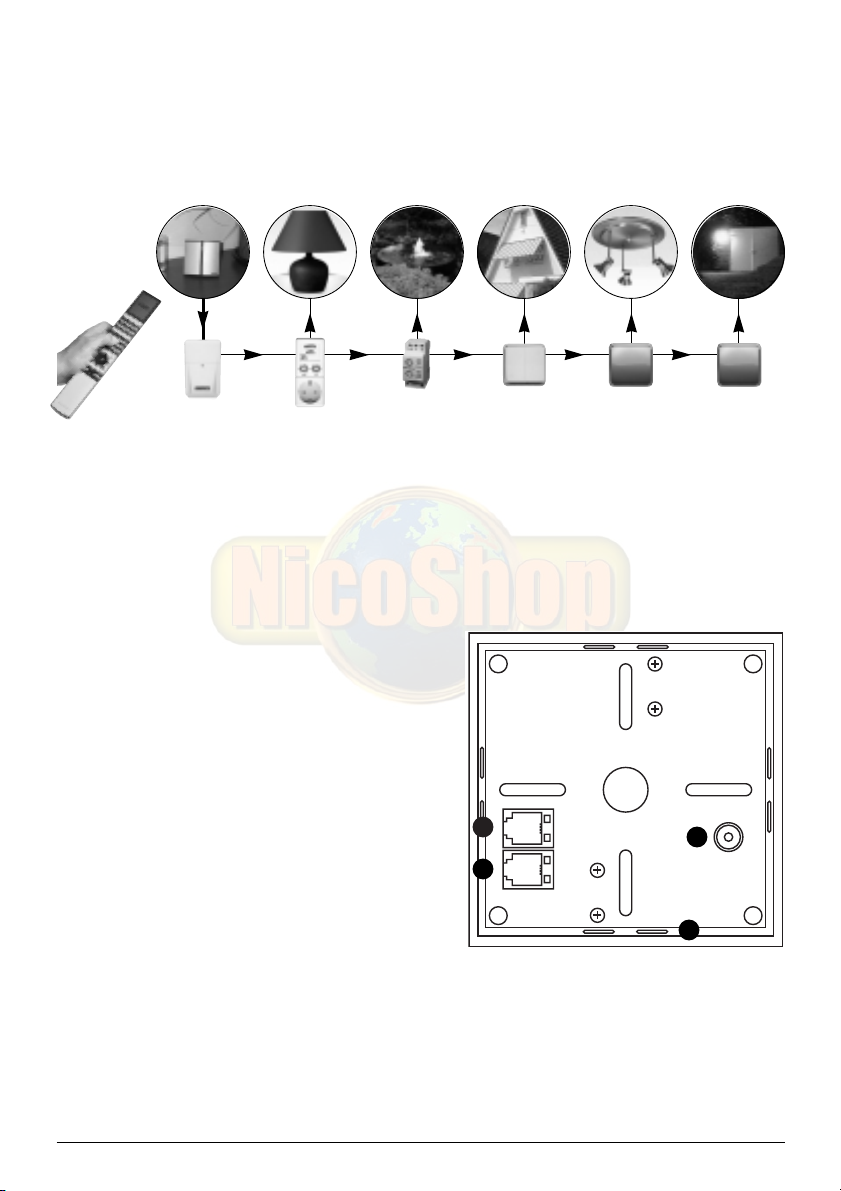
2. HOW DOES IT WORK?
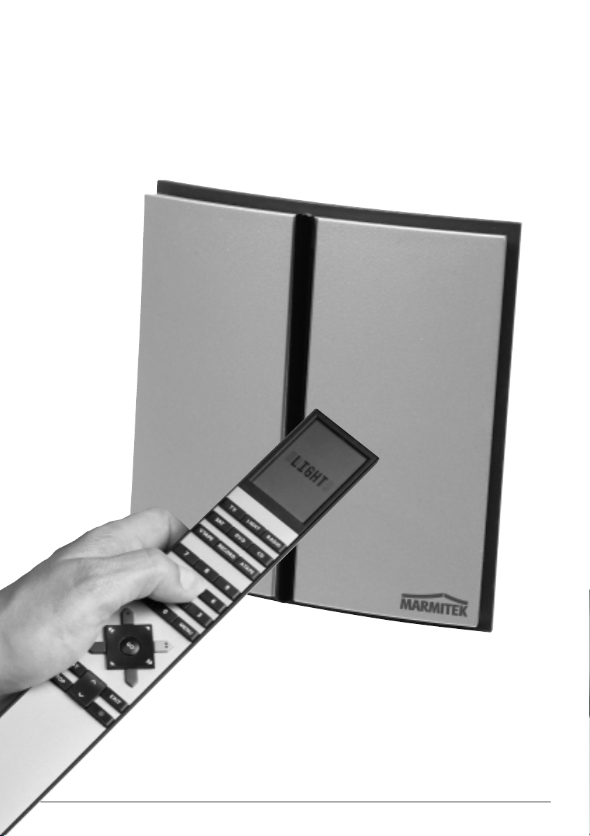
Aim the BEO4 infrared remote control at the ‘B&O to X-10 converter’. The XM10 power line
modem (available separately) transmits the command to your lights and equipment via the
mains. No extra wiring necessary.
( ( (
XM10 MARMITEK X-10 modules
Equip all lamps and appliances which you wish to control remotely with a Marmitek X-10
module. This module makes sure the device or light can be dimmed or switched on and off.
Marmitek X-10 modules are available in several versions. A short description of the available
X-10 modules can be found in chapter 6.
3.
INSTALLATION OF THE IR455
1. Connection for the cable to the XM10
power line modem
2. Connection for the power adapter
3. Connection for the cable to the PC
(see chapter 5.1)
4. Position for inserting the table stand
• Plug the XM10 connection cable into the
X-10 port (1) of the IR455. Plug the other
end of this cable into your XM10 power line
3
1
2
modem. Make sure you hear a clear audible
‘click’ when you connect the cable.
4
• Connect the power adapter to connection (2).
• Plug the power adapter and the XM10 power line modem into a wall socket.
• The IR455 is now ready for use.
NB: Do not place the IR455 close to a plasma screen. The radiation of the screen can disrupt
the infrared signal to the IR455.
5IR455
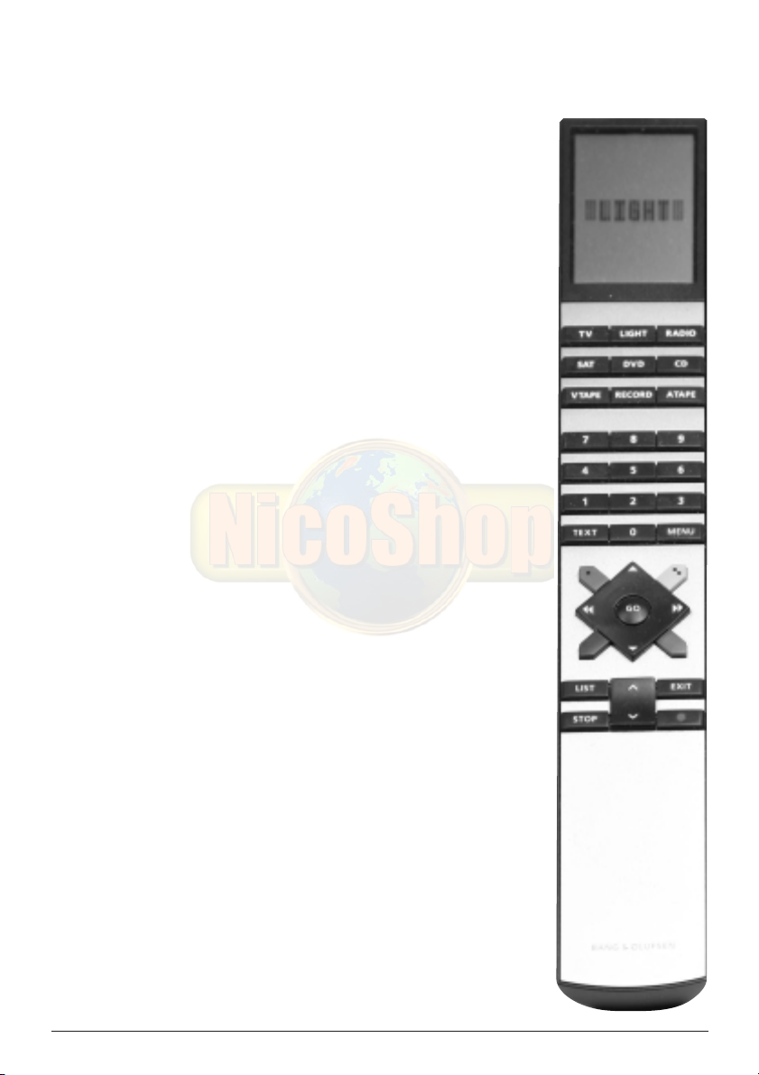
4. CONTROLLING YOUR MARMITEK X-10 MODULES
The IR455 uses the following buttons on your B&O remote control.
LIGHT: Press LIGHT to make sure the remote
control will work with the IR455.
0 t/m 9: Choose the lamp, device or setting
you wish to control (1-16).
GREEN, YELLOW, RED, BLUE:
GO: ON/activate the setting
STOP: OFF
Marmitek X-10 modules are all set to an address, consisting of a
letter (HouseCode) and a number (UnitCode). The IR455 is
configured to control Marmitek X-10 modules set to the addresses
A1-A16.
Settings (standard):
LIGHT - 1 - GO: Module A1 ON
LIGHT - 1 - STOP: Module A1 OFF
LIGHT - 1 - ▲: Module A1 BRIGHTER
LIGHT - 1 - ▼: Module A1 DIM
LIGHT - 2 - …: same for module A2
till
LIGHT -16 - …: same for module A16
Choose the desired setting.
The Marmitek X-10 system contains a function with which you can
turn all lights (on one HouseCode) on or off at the same time. To
activate this function, use the green button.
All lights on HouseCode A ON: LIGHT - GREEN - GO
All modules on HouseCode A OFF: LIGHT - GREEN - STOP
NB 1: You can select the UnitCodes 10-16 by pressing both
numbers consecutively. E.g. to select the module on
UnitCode 12: LIGHT - 1 - 2 - GO.
NB 2: As long as your BEO4 remote control is in LIGHT mode
(the word LIGHT is visible on the display), you do not need
to keep pressing the LIGHT button to switch or dim a new
module.
NB 3: By quickly pressing ▲ and ▼ the lights will be dimmed by
one step. By keeping ▲ and ▼ pressed, the lights will be
dimmed by multiple steps, until you let go of the button.
6 MARMITEK
5. CHANGING THE SETTINGS
You can change the settings of the IR455 using a PC that runs under MS Windows.
5.1. Connecting the device to the PC
Connect the PC cable to a free serial port (COM port) of your PC. The other end of the cable
can be connected to the ‘PC’ connection on the back of your IR455 (top connection).
5.2. Installing the software
• Place the CD-ROM in the CD-ROM drive. The software will start automatically. If the CD
does not start automatically, start the file setup.exe via your browser.
• Follow the instructions on your screen.
• When the installation is complete, choose: Programs > Marmitek > IR455.
• The program will start.
• Select the COM port (serial port) the IR455 is connected to and click GO.
If you do not know which COM port the device is connected to, choose a random port.
Choose e.g. COM port 1 and click ‘GO’. If COM port 1 is the right option, you will continue
to the next screen. If COM port 1 is not correct, you will receive the error message ‘Marmitek
IR455 not connected to CommPort 1’. Choose another COM port until you have found the
correct port.
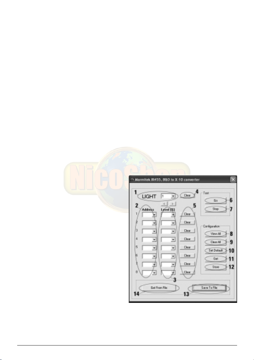
You will now see the following screen:
1. You are in the program screen for
button 1 (LIGHT - 1 - GO) of the BEO4
remote control. By pressing the >
button you will continue to the next
button. There are 20 possibilities: the
numbers 1-16 and the green, yellow,
red and blue buttons.
2. ADDRESS: With this option you can
indicate which X-10 modules should
be switched or dimmed when pressing
a button. You can have a maximum of
8 modules respond to one button
(atmospheric settings for e.g. reading
and watching TV).
3. LEVEL (%): With this option you can
set the brightness of the lights.
4. CLEAR: Clears all settings for this button. You can have a maximum of 8 modules
respond to one button (atmospheric settings for e.g. reading and watching TV).
5. CLEAR: This clears the setting per line.
6. GO: Simulates the GO button (e.g. LIGHT - 1 - GO) of the remote control. The command
is executed by the IR455.
7IR455

7. STOP: Simulates the STOP button (e.g. LIGHT - 2 - STOP) of the remote control. The
command is executed by the IR455.
8. VIEW ALL: Generates an overview of all your settings. See chapter 5.4 for more
information about the codes used.
9. CLEAR ALL: Clears all settings.
10. SET DEFAULT: Restores the factory settings.
11. GET: Reads the settings from the IR455. See chapter 5.4 for more information about the
codes used.
12. STORE: Saves the new settings to the IR455.
13. SAVE TO FILE: Saves your settings to a file.
14. GET FROM FILE: Retrieves the settings from a file you saved earlier.
5.2.1. The selection box LIGHT
With this option you can select the button on your B&O remote control you want to program.
Besides the buttons 1-16 you can also program the coloured buttons on the remote control.
GREEN = green button
RED = red button
YELLOW = yellow button
BLUE = blue button
5.2.2. The selection box ADDRESS
With these selection boxes you can select the addresses (A1-P16) of the X-10 modules you
want to respond to this button on your B&O remote control.
Instead of an address (a combination of a letter and a number), you can also just select a
HouseCode (A, B… P). If you choose a HouseCode, all modules using this code will respond
to the button at the same time.
5.2.3. The selection box LEVEL (%)
When you have chosen an address under "ADDRESS" (letter + number, e.g. A1), you have
the following options:
100% = ON
0% = OFF
5%, 10% ... 95% = directly set to the desired dim level.
ATTENTION: When using dimmer modules without a memory and switch modules (see
overview in chapter 6) you can only select 100% or 0%. If you select a dim value (e.g. 40%)
for these modules, the module will not respond.
When you have only chosen a HouseCode under "ADDRESS" (e.g. A), you have the following
options:
100% = ALL LIGHTS ON (only lamp modules with the HouseCode will respond)
0% = ALL MODULES OFF (all modules with the HouseCode will respond)
8 MARMITEK
5.2.4. Saving your settings
Once you have programmed all your settings, they can be saved to the IR455 by pressing
‘Store’. You can then disconnect the unit from the PC. The settings are saved even in the
event of a power failure.
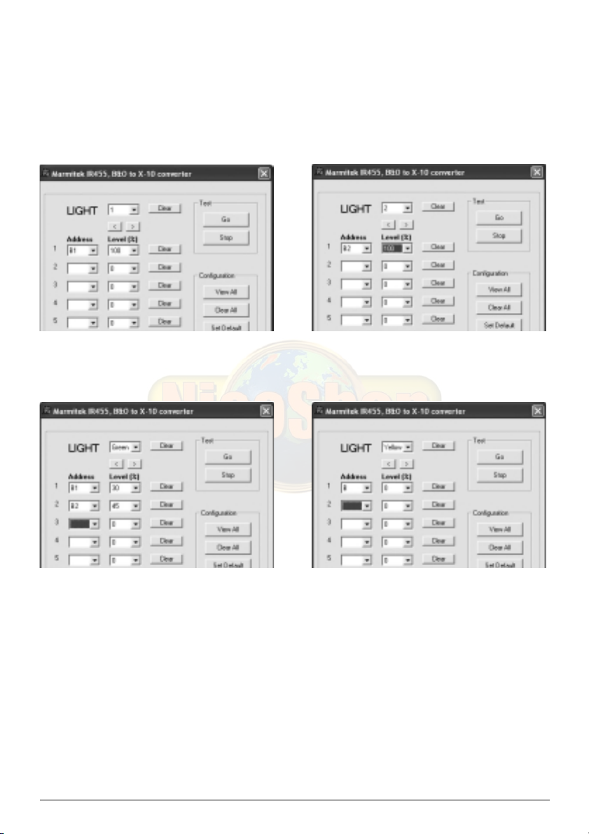
5.3. Example
You want to use button 1 to control the You want to use button 2 to control the
Marmitek X-10 module on address B1 Marmitek X-10 module on address B2
You want the green button to set module You want the yellow button to turn
B1 to 30% and module B2 to 45% off all your modules on HouseCode B
5.4. Configuration overview
When using the buttons in the ‘Configuration’ window and the button GET FROM FILE, a
configuration overview is shown.
The following codes are used:
Light 1 = 1:A1-100,2:,3:,4:,5:,6:,7:,8:
THIS MEANS:
Module A1 ON (100%)
(+ space for 7 other settings)
9IR455

Light 1 = 1:A1-100,2:A3-45,3:A4-0,4:,5:,6:,7:,8:
THIS MEANS:
Module A1 ON (100%)
Module A3 ON (45%)
Module A4 OFF (0%)
(+ space for 5 other settings)
6. MARMITEK X-10 MODULES
Art.Nr. Description Application: Possibilities with the IR455
country
specific
LM12 Plug in module (table lamps). On, off, manual dimming.
No memory function.
08930 LW11 In-wall switch (ceiling lights, spots). On, off, direct to programmed
Dimmer with memory function. dim level, manual dimming.
09534 LWM1 MicroModule for behind your On, off, direct to programmed
existing switch. dim level, manual dimming.
Dimmer with memory function.
08932 LD11 DIN rail module (meter box, On, off, direct to programmed
several types of lighting). dim level, manual dimming.
Dimmer with memory function.
country
specific
AM12 Plug-in module (tube lighting, On, off.
devices).
08931 AW10 In-wall switch. On, off.
09463 AW12 MicroModule for behind your On, off.
existing switch.
09300 AWM2 MicroModule for behind your On, off.
existing switch.
08933 AD10 DIN rail module (meter box). On, off.
08954 SW10 Sun blinds switch (blinds, Up, down.
projection screen).
10 MARMITEK

( ( (
XM10 MARMITEK X-10 modules
Visit www.marmitek.com for more information:
www.marmitek.com/in-wall: for built-in switches and Micromodules
www.marmitek.com/plug-in: for plug-in modules, screw-in modules etc.
7. USING THE MARMITEK X-10 SYSTEM WITH MULTIPLE
PHASES
In some houses the energy supply is not 1x 230V, but 3x 230V. This is called a 3-phase
system. In these cases, it can be necessary to couple these phases for the Marmitek X-10
signals. You can couple the phases by using FD10 phase coupling filters (art. nr. 08934). You
need to do this when your wall sockets and light points are divided over multiple phases.
Multiple groups do not pose any problems when using the Marmitek X-10 signal. For larger
buildings we advise using an active 3-phase amplifier (CAT3000, art. nr. 09304) instead of
phase coupling filters.
More information on X-10 signals and your mains can be found on:
www.marmitek.com/X10signal
8. TECHNICAL INFORMATION
Infrared reception frequency: 455kHz
Infrared range: max. 10 meter. When the infrared signal has been converted
to X-10, the signal range is extended to the entire house.
Dimensions: 105x105x30mm
Power: 12V AC/DC 350mA
X-10 command set: Standard X-10 (ON, OFF, DIM, BRIGHT, ALL LIGHTS ON, ALL
UNITS OFF) and Extended X-10 (directly calling up the
dim values: is supported by dimmer modules with a
memory function)
X-10 Collision detection: Present
11IR455

12 MARMITEK

IR455 B&O to X-10 CONVERTER
Gebrauchsanweisung
Herzlichen Dank, dass Sie sich für ein Marmitek Produkt entschieden haben. Lesen Sie diese
Anleitung sorgfältig durch, bevor Sie das Produkt in Betrieb nehmen.
SICHERHEIT
Verwenden Sie dieses Gerät, um Kurzschluss vorzubeugen, ausschließlich in trockenen
Räumen und setzen Sie das Gerät nicht Regen oder Feuchtigkeit aus. Nicht nahe eines Bades,
Schwimmbades usw. verwenden. Das Produkt niemals aufmachen. Überlassen Sie
Reparaturen oder Wartungsarbeiten nur einem Fachmann. Bei unzweckmäßigem Gebrauch,
selbst angebrachten Änderungen oder Reparaturen, erlöschen sämtliche Garantieansprüche.
INHALTSVERZEICHNIS
1. Set-Inhalt ___________________________________________________________________14
2. Wie funktioniert es?__________________________________________________________ 15
3. Installation der IR455 _________________________________________________________15
4. Bedienen Ihrer Marmitek X-10 Module __________________________________________16
5. Die Einstellungen ändern______________________________________________________ 17
5.1. Anschluss an den PC ___________________________________________________ 17
5.2. Installation der Software ________________________________________________ 17
5.2.1. Das Eingabefeld LIGHT __________________________________________________18
5.2.2. Das Eingabefeld ADDRESS _______________________________________________ 18
5.2.3. Das Eingabefeld LEVEL (%) ______________________________________________ 18
5.2.4. Ihre Einstellungen speichern _____________________________________________ 19
5.3. Programmierbeispiel ____________________________________________________19
5.4. Konfigurationsübersicht _________________________________________________20
6. Marmitek X-10 Module _______________________________________________________20
7. Inbetriebnahme des Marmitek X-10 Systems bei mehr als einer Phase ________________ 21
8. Technische Daten ____________________________________________________________ 21
13IR455

1. SET-INHALT
1. IR455 "B&O to X-10 converter" [Konverter/Umformer] Haupteinheit
2. Speisungsadapter
3. Verbindungskabel für das XM10 Stromnetzmodem*
4. Verbindungskabel für den PC
5. Tischständer
6. CD ROM mit Software
3..
1. 2.
4. 5. 6.
* Zur Verwendung des IR455 benötigen Sie ein XM10 Stromnetzmodem. Dieses ist einzeln
erhältlich:
Art.-Nr. Beschreibung Zur Verwendung in:
08942 XM10E Stromnetzmodem Ländern mit Eurostecker
09231 XM10U Stromnetzmodem Ländern mit englischem Stecker (UK, Malta)
- - - - TM523 / PL513 / PSC05 110V-Modelle (USA)
14 MARMITEK
 Loading...