

Marantz UD-9004 Service Manual
Service
UD90
UD9004 /
U1B/N1B/S1B/R1B
SUPER AUDIO CD/
ss
Manual
SECTION PAGE
SERVICE HINTS AND TOOLS......................................................................................................1
SAFETY PRECAUTIONS
DIMENSION
WIRE ARRANGEMENT
DISASSEMBLY
AJUSTING THE POSITION OF THE LOADER PANEL
DIAGNOSTICS OF OPTICAL PICKUP
AND REPLACING FE MAIN P.W.B AND BD MECHANISM UNIT ASSY
SERVICE MODE
VERSION UPGRADE PROCEDURE OF FIRMWARE
TROUBLE SHOOTING
BLOCK DIAGRAM.......................................................................................................................45
SEMICONDUCTORS
PRINTED WIRING BOARDS
NOTE FOR PARTS LIST
PARTS LIST OF P.W.B. UNIT
WIRING DIAGRAM
EXPLODED VIEW
PARTS LIST OF EXPLODED VIEW..........................................................................................131
EXPLODED VIEW OF SACD MECHANISM
POINTS OF GREASING
PARTS LIST OF EXPLODED VIEW OF SACD MECHANISM
PACKING VIEW
PARTS LIST OF PACKING & ACCESSORIES
MEASURING METHOD AND WAVEFORMS
NOTE FOR SCHEMATIC DIAGRAM
SCHEMATIC DIAGRAMS
Please use this service manual with referring to the user guide ( D.F.U. ) without fail.
..................................................................................................................................3
.............................................................................................................................5
.........................................................................................................................19
........................................................................................................................137
BLU-RAY DISC PLAYER
TABLE OF CONTENTS
..............................................................................................................2
................................................................................................................4
..............................................................16
....................................17
...............................................................29
...............................................................................................................33
..................................................................................................................47
......................................................................................................69
.............................................................................................................81
.....................................................................................................82
...................................................................................................................129
.....................................................................................................................130
.............................................................................133
...........................................................................................................134
..................................................135
.........................................................................138
............................................................................139
........................................................................................144
.........................................................................................................145
S0019-2V03DM/DG0912
UD9004
Copyright 2009 D&M Holdings Inc. All rights reserved.
WARNING: Violators will be prosecuted to the maximum extent possible.
Ver.3
Please refer to
MODIFICATION
Part no. 90M37AK855030
First Issue 2009.12
NOTICE
MARANTZ DESIGN AND SERVICE
Using superior design and selected high grade components,
MARANTZ
company has created the ultimate in stereo sound.
Only original
MARANTZ
parts can insure that your
MARANTZ
product will continue to perform to the VSHFL¿FDWLRQV for
which it is famous.
Parts for your
MARANTZ
equipment are generally available to our National Marantz Subsidiary or Agent.
ORDERING PARTS :
3DUWV FDQ EH RUGHUHG HLWKHU E\ PDLO RU E\ )D[ ,Q ERWK FDVHV WKH FRUUHFW SDUW QXPEHU KDV WR EH VSHFL¿HG
The following information must be supplied to eliminate delays in processing your order :
1. Complete address
2. Complete part numbers and quantities required
3. Description of parts
4. Model number for which part is required
5. Way of shipment
6. Signature : any order form or Fax. must be signed, otherwise such part order will be considered as null and void.
SHOCK, FIRE HAZARD SERVICE TEST :
CAUTION : After servicing this appliance and prior to returning to customer, measure the resistance between either primary
AC cord connector pins (with unit NOT connected to AC mains and its Power switch ON), and the face or Front Panel of
product and controls and chassis bottom.
Any resistance measurement less than 1 Megohms should cause unit to be repaired or corrected before AC power is applied,
and YHUL¿HG before it is return to the user/customer.
Ref. UL Standard No. 60065.
,Q FDVH RI GLI¿FXOWLHV GR QRW KHVLWDWH WR FRQWDFW WKH Technical
Department at above mentioned address.
NOTE ON SAFETY :
Symbol Fire or electrical shock hazard. Only original parts should be used to replaced any part marked with symbol .
$Q\ RWKHU FRPSRQHQW VXEVWLWXWLRQ RWKHU WKDQ RULJLQDO W\SH PD\ LQFUHDVH ULVN RI ¿UH RU HOHFWULFDO VKRFN KD]DUG
安全上の注意:
がついている部品は、安全上重要な部品です。必ず指定されている部品番号のものを使用して下さい。
64"
."3"/5; ".&3*$" */$
$03103"5& %3*7&
.")8") /&8 +&34&:
64"
+"1"/
%. )PMEJOHT *OD
%. #6*-%*/( /*44)*/$)0
,"8"4",*,6 ,"8"4",*4)*
,"/"("8" +"1"/
&6301& 53"%*/(
%. &6301& # 7
1 0 #09 #6*-%*/( 4*-7&310*/5
#&&.%453""5 ." &*/%)07&/
5)& /&5)&3-"/%4
1)0/&
'"9
$"/"%"
%. $BOBEB *OD
"11-& $3&&, #-7%
."3,)". 0/5"3*0 -3 #
$"/"%"
1)0/&
'"9
,03&"
%. 4"-&4 "/% ."3,&5*/( ,03&" -5%
':&0/ #-%(
#"/10%0/( 4&0$)0(6
4&06- ,03&"
1)0/&
'"9
$)*/"
%. 4"-&4 "/% ."3,&5*/( 4)"/()"* -5%
300. 4)"/()"* "*31035 $*5: 5&3.*/"/0 /"/+*/( 8&45 30"% 4)"/()"*
$)*/"
5&-
'"9
UD9004
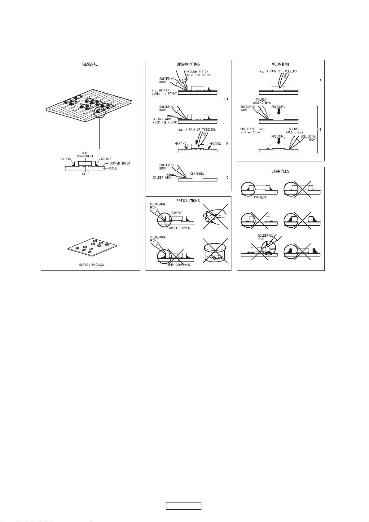
SERVICE HINTS
SERVICE HINTS AND TOOLS
1
UD9004

SAFETY PRECAUTIONS
The following check should be performed for the continued protection of the customer and service technician.
LEAKAGE CURRENT CHECK
Before returning the unit to the customer, make sure you make either (1) a leakage current check or (2) a line to chassis
resistance check. if the leakage current exceeds 0.5 milliamps, or if the resistance from chassis to either side of the power
cord is less than 460 kohms, the unit is defective.
LASER RADIATON
Caition - Class 1M visible and invisible laser radiation when open.
Do not view directly optical instruments.
CAUTION
Please heed he points listed below during servicing and inspection.
Heed the cautions!
Spots requiring particular attention when servicing, such
as the cabinet, parts, chassis,etc., have cautions indicated
on labels. be sure to heed these causions and the cautions
indicated in the handling instructions.
Caution concerning electric shock!
(1) An AC voltage is impressed on this set, so touching
internal metal parts when the set is energized could
cause electric shock. Take care to avoid electric
shock, by for example using an isolating transformer
and gloves when servicing while the set is energized,
unplugging the power cord when replacing parts, etc.
(2) Tere are high voltage parts inside. Handle with extra
care when the set is energized.
Caution concerning disassembly and
assembly!
Through great care is taken when manufacturing parts
from sheet metal, there may in some rare cases be burrs
RQ WKH HGJHV RI SDUWV ZKLFK FRXOG FDXVH LQMXU\ LI ¿QJHUV
are moved across them. Use gloves to protect your hands.
Only use designated parts!
The set's parts have specific safety properties (fire
resistance, voltage resistance, etc.). For replacement parts,
be sure to use parts which have the same poroperties. In
particular, for the important safety parts that are marked
z
on wiring diagrams and parts lists, be sure to use the
designated parts.
Be sure to mount parts and arrange the wires
as they were originally!
For safety seasons, some parts use tape, tubes or other
insulating materials, and some parts are mounted away
from the surface of printed circuit boards. Care is also
taken with the positions of the wores omsode amd clamps
are used to keep wires away from heating and high voltage
parts, so be sure to set everything back as it was originally.
◎
◎
◎
◎
◎
Inspect for safety after servicing!
Check that all screws, parts and wires removed or
disconnected for servicing have been put back in their
original positions, inspect that no parts around the area that
has been serviced have been negatively affected, conduct
an inslation check on the external metal connectors and
between the blades of the power plug, and otherwise
check that safety is ensured.
(Insulation check procedure)
Unplug the power cord from the power outlet, disconnect
the antenna, plugs, etc., and turn the power switch on.
Using a 500V insulation resistance tester, check that the
inplug and the externally exposed metal parts (antenna
terminal, headphones terminal, input terminal, etc.) is
0ȍ RU JUHDWHU ,I LW LV OHVV WKH VHW PXVW EH LQVSHFWHG DQG
repaired.
◎
Many of the electric and structural parts used in the set
have special safety properties. In most cases these
properties are difficult to distinguish by sight, and using
replacement parts with higher ratings (rated power and
withstand voltage) does not necessarily guarantee that
safety performance will be poreserved. Parts with safety
properties are indicated as shown below on the wiring
diagrams and parts lists is this service manual. Be sure to
replace them with parts with the designated part number.
(1) Schematic diagrams ......Indicated by the zmark.
(2) Parts lists ......Indicated by the z mark.
Using parts other than the designated
SDUWV FRXOG UHVXOW LQ HOHFWULF VKRFN ¿UHV
or other dangerous situations.
Concerning important safety
parts
CAUTION
2
UD9004
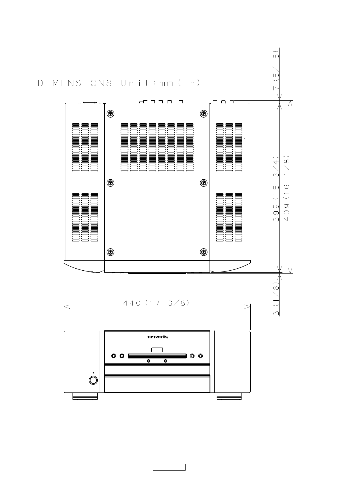
DIMENSION
3
UD9004

ワイヤー整形図
調整や部品の交換等により、ワイヤー類の結束をはずしたり移動させた場合には、それらの作業が完了した時点で
ワイヤーの整形をおこなってください。正しく整形されてないとノイズ発生の原因となることがあります。
上面からみたワイヤー整形
Front Panel side
Back Panel side
4
DVD-A1UD

DISASSEMBLY
Y
Y
• Disassemble in order of the arrow of the figure of following flow.
• In the case of the re-assembling, assemble it in order of the reverse of the following flow.
• In the case of the re-assembling, observe "attention of assembling" it.
• When reattaching the BOTTOM COVER after removing it, be careful that it does not run against the REAR
PANEL.
TOP COVER
SIDE COVER (L) and (R) SUB ASSY
AUDIO SUR/BACK/S_W UNIT
Refer to "DISASSEMBLY
2.AUDIO SUR/BACK/S W UNIT" Refer to "DISASSEMBLY 1.FRONT PANEL ASSY"
and "EXPLODED VIEW" 6.VIDEO/MAIN UNIT SUB ASSY" and "EXPLODED VIEW"
AUDIO SUR/BACK/S W UNIT
(Ref. No. of EXPLODED VIEW : A-3) VIDEO UNIT (Ref. No. of EXPLODED VIEW : B-1)
AUDIO SUR/CENTER UNIT
Refer to "DISASSEMBLY (Ref. No. of EXPLODED VIEW : E) STANDBY LED UNIT
3.AUDIO SUR/CENTER UNIT" (Ref. No. of EXPLODED VIEW : B-4)
and "EXPLODED VIEW"
AUDIO SUR/CENTER UNIT
(Ref. No. of EXPLODED VIEW : B-5) Refer to "DISASSEMBLY
AUDIO FRONT L/R UNIT
Refer to "DISASSEMBLY
4.AUDIO FRONT L/R UNIT"
and "EXPLODED VIEW"
AUDIO FRONT L/R UNIT Refer to "DISASSEMBLY
(Ref. No. of EXPLODED VIEW : A-1) 8.POWER UNIT"
AUDIO XLR UNIT
Refer to "DISASSEMBLY (Ref. No. of EXPLODED VIEW : C)
5.AUDIO XLR UNIT"
and "EXPLODED VIEW"
AUDIO XLR UNIT Refer to "DISASSEMBLY
(Ref. No. of EXPLODED VIEW : A-2) 9.MECHA ASSY"
VIDEO/MAIN UNIT SUB ASSY
and "EXPLODED VIEW" FRONT UNIT
(Ref. No. of EXPLODED VIEW : D) KEY UNIT
MAIN UNIT (Ref. No. of EXPLODED VIEW : B-3)
DIGITAL CHASSIS SUB ASSY
7.DIGITAL CHASSIS SUB ASSY"
and "EXPLODED VIEW"
POWER UNIT
and "EXPLODED VIEW"
POWER UNIT
MECHA ASS
and "EXPLODED VIEW"
MECHA ASSY
(Ref. No. of EXPLODED VIEW : F)
FRONT PANEL ASS
Refer to "DISASSEMBLY
5
UD9004

About the photos used for descriptions in the “DISASSEMBLY” section.
• The direction from which the photographs used herein were photograph ed is indicated at "Direction of photograph: ***" at
the left of the respective photographs.
• Refer to the table below for a description of the direction in which the photos were taken.
• Photographs for which no direction is indicated were taken from above the product.
The viewpoint of each photograph
Direction of photograph: B
(Photografy direction)
[View from above]
Direction of photograph: C
Direction of photograph: A
1. FRONT PANEL ASSY
Proceeding : TOP COVER → SIDE COVER (L) and (R) SUB ASSY
→ FRONT PANEL ASSY
Front side
Direction of photograph: D
(1) Remove the screws.
Viewfrombottom
6
UD9004
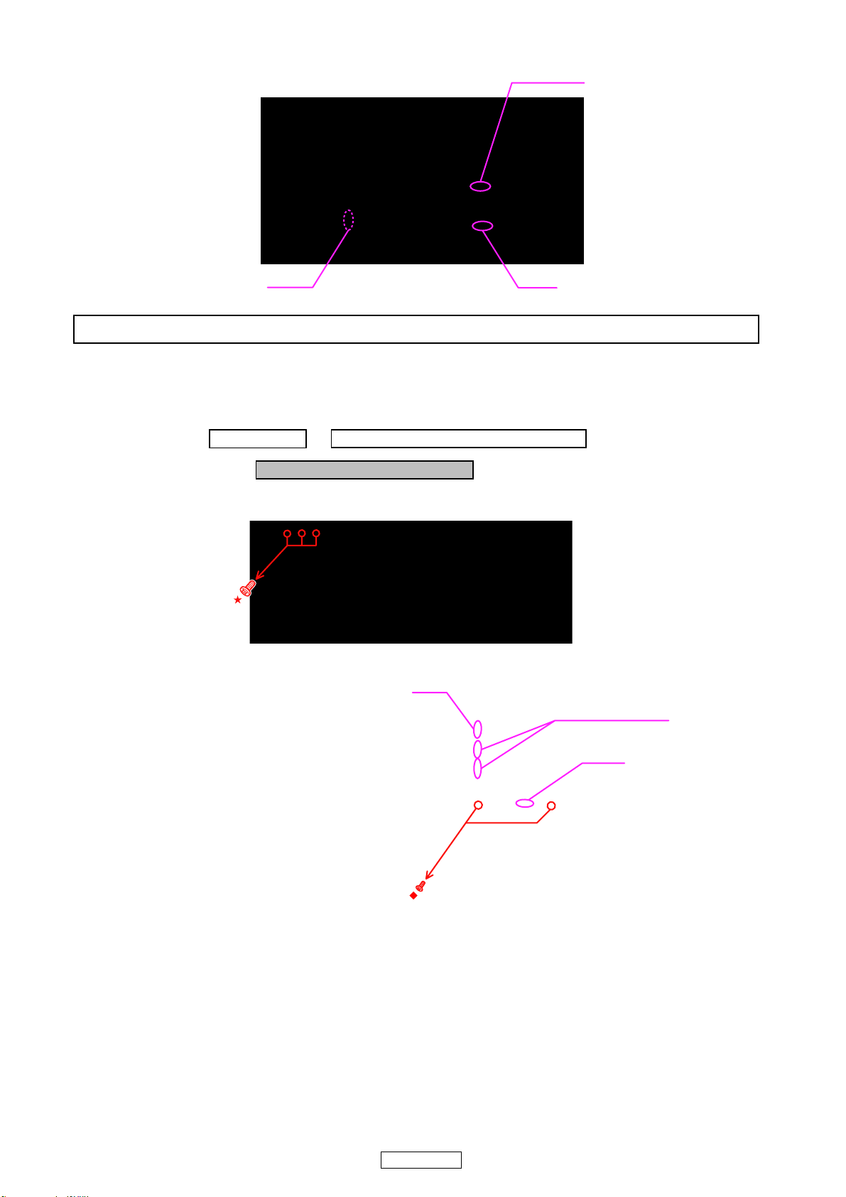
(2) Remove the screws. Disconnect the connector wire and FFC Cable.
FFC Cable
JF08JF02
Please refer to "EXPLODED VIEW" for the disassembly method of each P.W.B included in FRONT PANEL ASSY.
2. AUDIO SUR/BACK/S_W UNIT
Proceeding : TOP COVER →→ SIDE COVER (L) and (R) SUB ASSY
AUDIO SUR/BACK/S_W UNIT
(1) Remove the screws.
Direction of photograph: A
(2) Disconnect the connector wires and FFC cables then remove the screws.
JG51
FFC Cable
JG52
7
UD9004
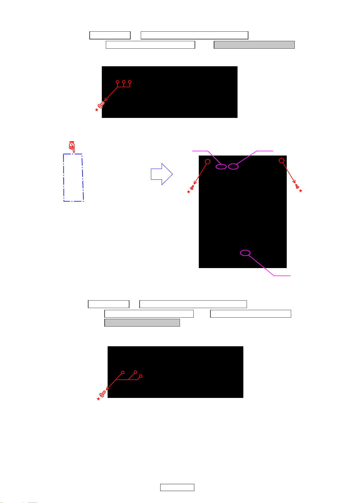
3. AUDIO SUR/CENTER UNIT
手順 : TOP COVER →
→
AUDIO SUR/BACK/S_W UNIT AUDIO SUR/CENTER UNIT
(1) Remove the screws.
Direction of photograph: A
(2) Removethescrews.
SIDE COVER (L) and (R) SUB ASSY
→
J554J552
4. AUDIO FRONT L/R UNIT
Proceeding : TOP COVER →
→
AUDIO SUR/BACK/S_W UNIT AUDIO SUR/CENTER UNIT
→
AUDIO FRONT L/R UNIT
(1) Removethescrews.
Direction of photograph: A
J852
SIDE COVER (L) and (R) SUB ASSY
→
8
UD9004
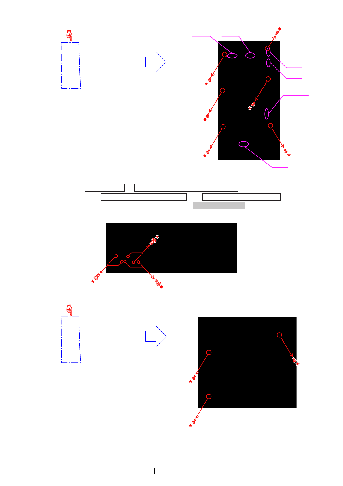
(2) DisconnecttheconnectorwireandFFCcables,thenremovethescrews.
5. AUDIO XLR UNIT
Proceeding : TOP COVER →
→
AUDIO SUR/BACK/S_W UNIT AUDIO SUR/CENTER UNIT
→
AUDIO FRONT L/R UNIT AUDIO XLR UNIT
J807
J801
SIDE COVER (L) and (R) SUB ASSY
→
→
JH01
JH02
FFC Cable
J805
(1) Remove the screws.
Direction of photograph: A
(2) Remove the screws.
9
UD9004
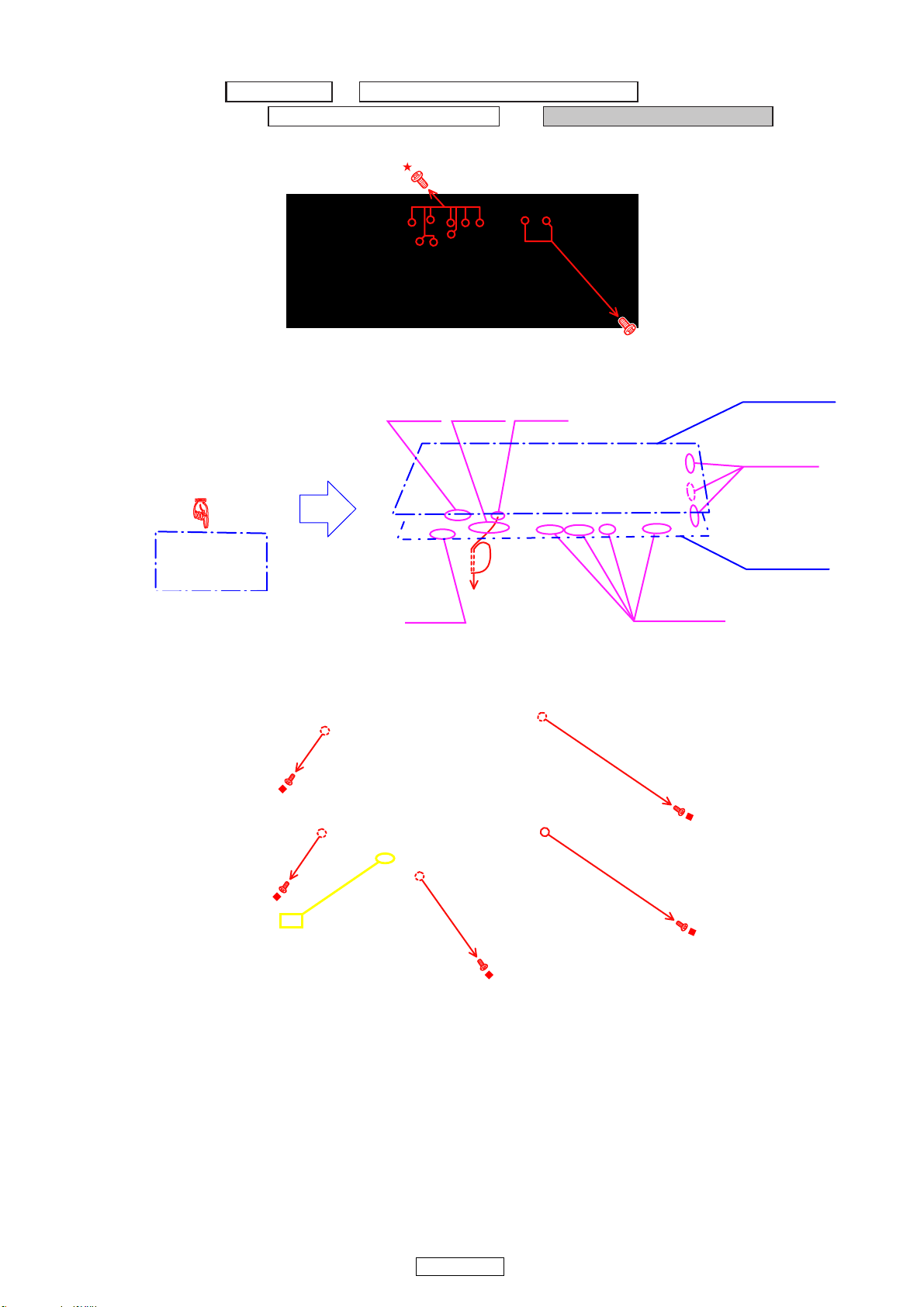
6.VIDEO/MAIN UNIT SUB ASSY
Proceeding : TOP COVER →
→
AUDIO SUR/BACK/S_W UNIT VIDEO/MAIN UNIT SUB ASSY
(1) Remove the screws.
Direction of photograph: A
(2) Disconnect the connector wire and FFC cables.
Direction of photograph: B
SIDE COVER (L) and (R) SUB ASSY
CX051
CY151
→
ً
VIDEO UNIT
CX031
FFC Cable
MAIN UNIT
CX044
(3) Cut the wire clamp band. Remove the screws, then remove “VIDEO/MAIN UNIT SUB ASSY". Refer to the diagram
next page for instructions on removing.
cut
FFC Cable
10
UD9004
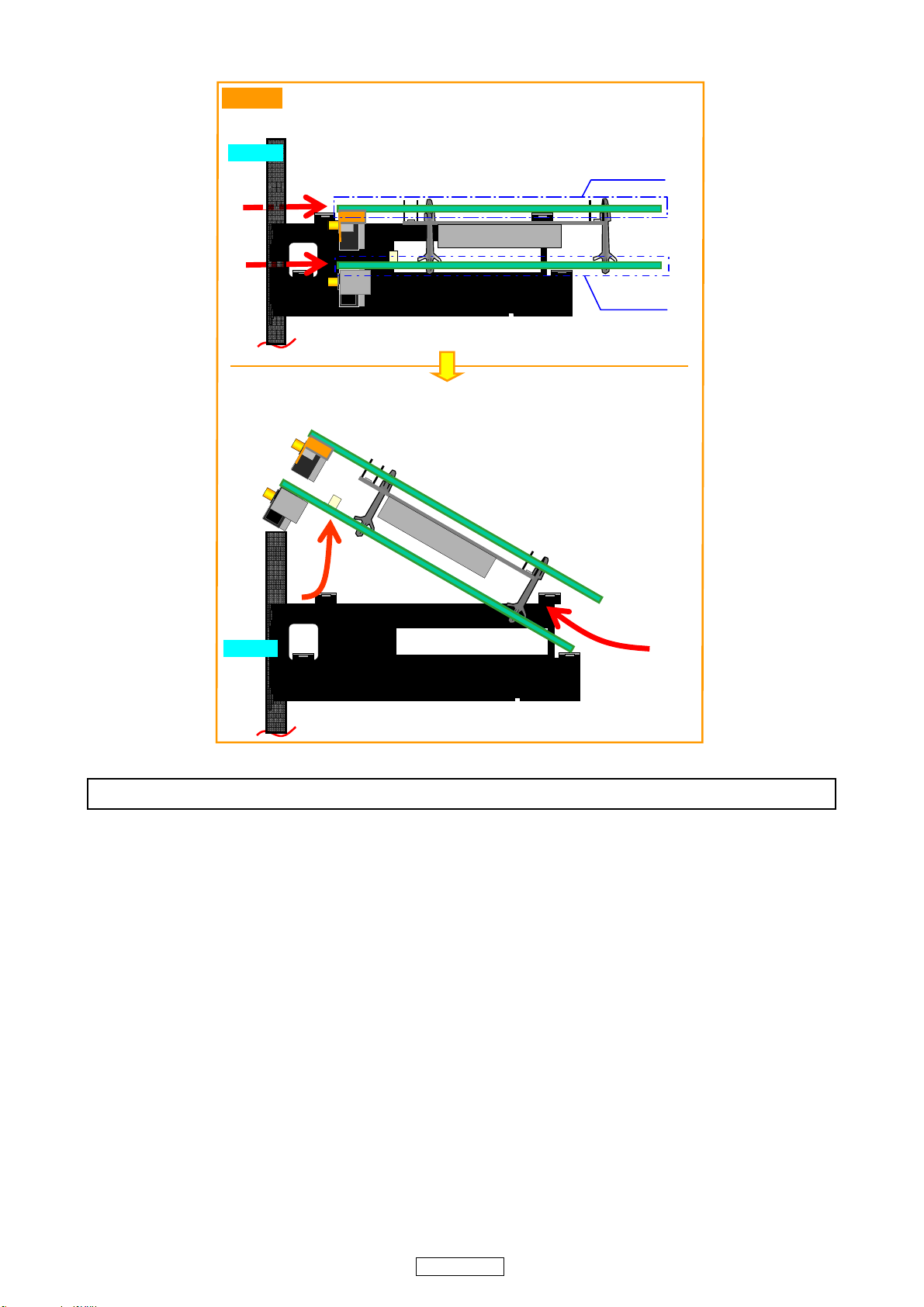
Side view
①Slide “VIDEO/MAIN UNIT SUB ASSY” in the direction of the arrow.
R/P Side
①
①
②Lift “VIDEO/MAIN SUB ASSY” in the direction of the arrow.
③Draw out in the direction of the arrow.
VIDEO UNIT
MAIN UNIT
②
R/P Side
③
Pleasereferto"EXPLODED VIEW"forthedisassemblymethodofeachP.W.BincludedinVIDEO/MAINUNITSUBASSY.
11
UD9004
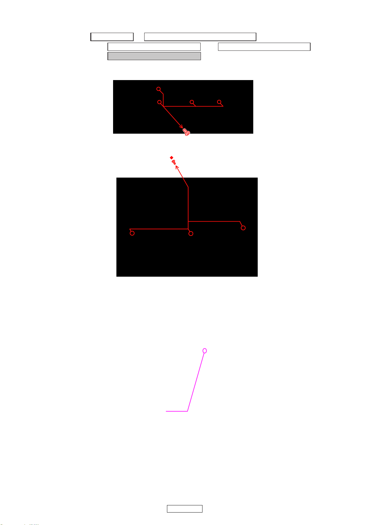
7.DIGITAL CHASSIS SUB ASSY
Proceeding : TOP COVER →
→
AUDIO SUR/BACK/S_W UNIT VIDEO/MAIN UNIT SUB ASSY
→
DIGITAL CHASSIS SUB ASSY
(1) Remove the screws.
Direction of photograph: A
SIDE COVER (L) and (R) SUB ASSY
→
ً
(2) Disconnect the connector wire.
CY033
12
UD9004
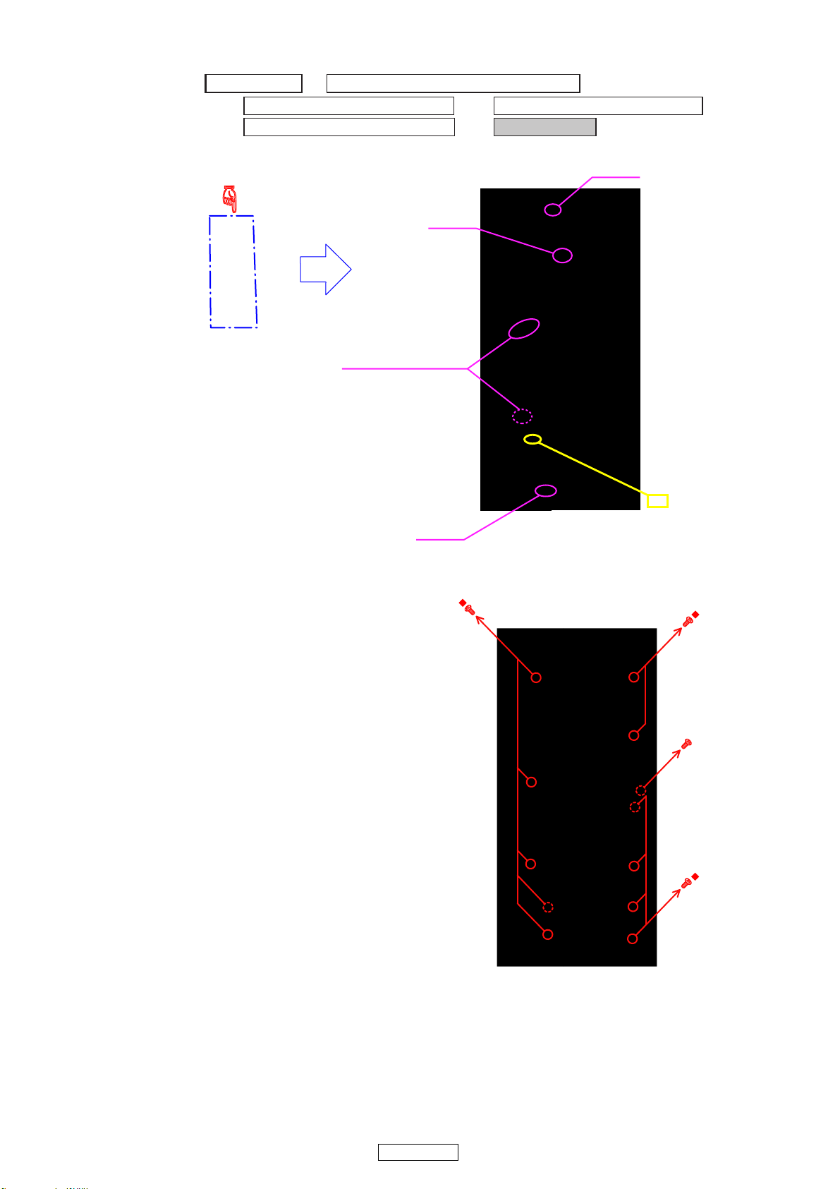
8. POWER UNIT
Proceeding : TOP COVER →
→
AUDIO SUR/BACK/S_W UNIT VIDEO/MAIN UNIT SUB ASSY
→
DIGITAL CHASSIS SUB ASSY POWER UNIT
(1) Cut the wire clamp band, then disconnect the connector wires.
SIDE COVER (L) and (R) SUB ASSY
CX021
Cord holder : LOOSE
→
→
CX023
(2) Remove the screws.
cut
CY062
ً
13
UD9004
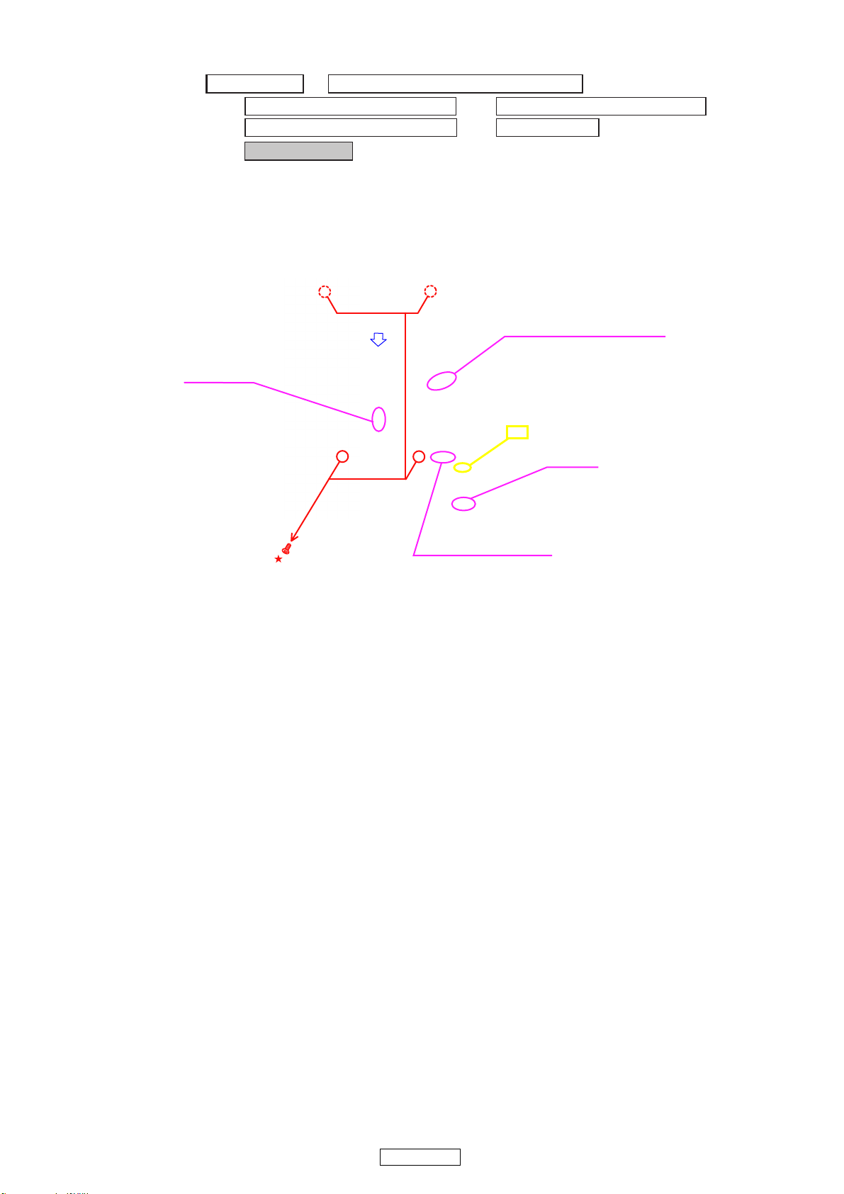
9. MECHA ASSY
Proceeding : TOP COVER →
→
AUDIO SUR/BACK/S_W UNIT VIDEO/MAIN UNIT SUB ASSY
→
DIGITAL CHASSIS SUB ASSY POWER UNIT
→
MECHA ASSY
(1) Cut the wire clamp band, then disconnect the connector wires. Remove the screws, then remove “MECHA ASSY” in
the direction of the arrow.
b When mounting the mechanism, adjust the position of the loader panel. (See page 16)
FFC Cable
SIDE COVER (L) and (R) SUB ASSY
→
→
Cord holder : LOOSE
cut
CY062
Cord holder : LOOSE
14
UD9004
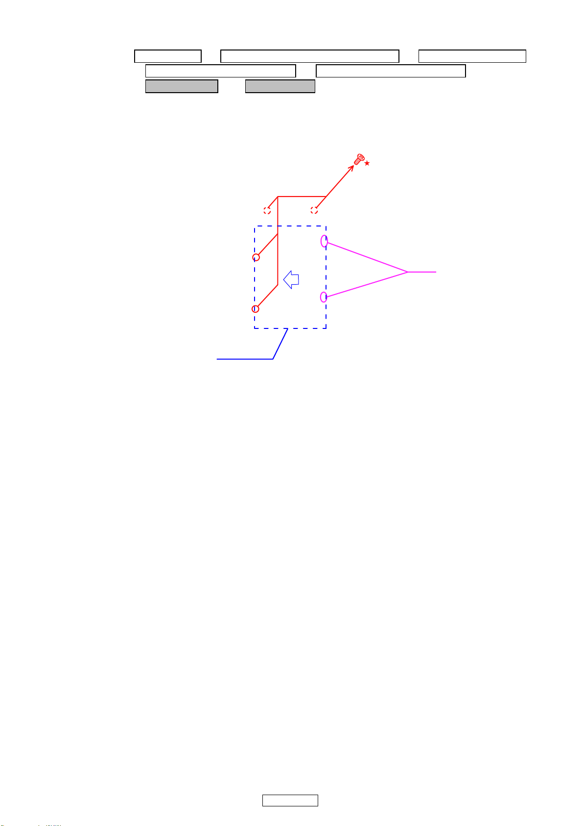
Removing discs
Proceeding : TOP COVER → SIDE COVER (L) and (R) SUB ASSY → FRONT PANEL ASSY
→ VIDEO/MAIN UNIT SUB ASSY → DIGITAL CHASSIS SUB ASSY
→ BLIND SHEET → Clamp cover
(1) Remove the screws( ★ mark), then lift the clamp cover to unhook the hooks.
(2) Remove the Clamp cover in the direction of the arrow, then remove the disc inside.
b¶ Be careful not to scratch the disc when removing the Clamp cover.
Hook
clamp cover
15
UD9004
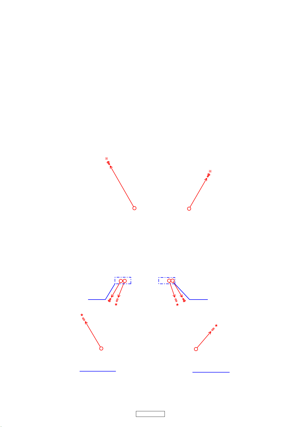
AJUSTING THE POSITION OF THE LOADER PANEL
Perform this adjustment when repairing for uneven gaps around the loader panel (top, bottom, left and right) and when remounting mechanisms removed when making repairs.
<Preparations>
・
First turn on the power, open and close the tray once, then turn the power off.
・ Check the various actual gaps.
・ Loose the screws marked d and b fixing the mechanism in place.
1.Adjusting the gaps
1.1. Adjusting the left and right gaps
(1) With the mechanism pressing against the front, adjust so that there is no gap on the left and right.
1.2. Adjustingthetopandbottomgaps
(1) Using a hexagonal wrench, turn the screws marked ★ on the left and right to adjust the top and bottom gaps of the left
and right trays.
(When it turns to clockwise, the opening above spreads.)
(2) Fasten the mechanism using the two screws marked d.
(3) Fasten the mechanism using the two screws marked b.
View RView L
ً ً
Detail of View L
Detail of View R
2.Final check
After completing the operations, turn on the power and open and close the tray once to check the gap.
16
UD9004
DIAGNOSTICS OF OPTICAL PICKUP
AND REPLACING FE MAIN P.W.B AND BD MECHANISM UNIT ASSY
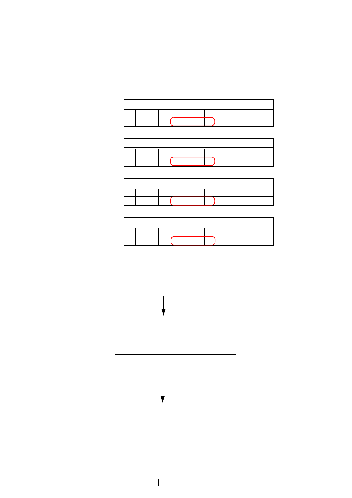
Make failure diagnostics of the Optical Pickup as follows.
If the laser drive current (Iop) becomes more than ± 12[mA] of the initial value, the Optical Pickup should be replaced.
The laser drive current initial value is checked by "Iop checked Method" of next page.
In case of replacing the Pickup, change the whole part of the FE Main P.W.B and BD Mechanism Unit Assy.
No mechanical adjustment is necessary after the replacement.
Laser drive current initial value:
FL Display (The display part of 13 digits)
12345678910111213
CD:
DVD:
BD(SL):
T21-mmmm-nnnn
FL Display (The display part of 13 digits)
12345678910111213
T22-mmmm-nnnn
FL Display (The display part of 13 digits)
12345678910111213
T23-mmmm-nnnn
BD(DL):
FL Display (The display part of 13 digits)
12345678910111213
T24-mmmm-nnnn
Disc no read, unsteady playback, etc.
Laser drive current (Iop) check
HF wave form check
(Refer to WAVE FORMS)
Current value of the BD, DVD or CD IOP is
± 12[mA] or more the initial value.
FE Main P.W.B. and BD Mechanism Unit
Assy replacing
17
UD9004
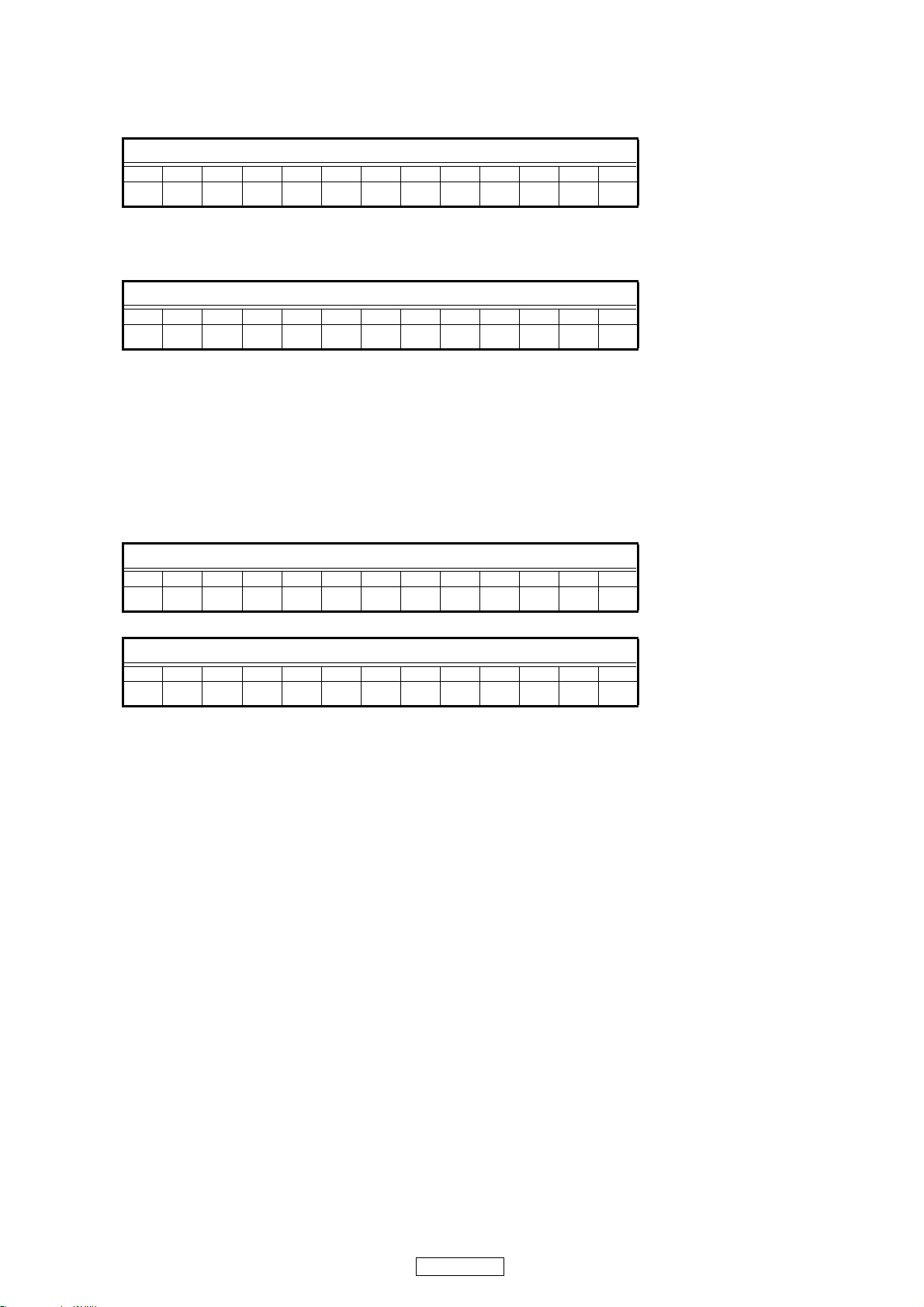
1.Iop checked Method
Select the laser ON/OFF(CD/DVD/BD)mode of the test mode, and check the IOP value of CD laser, DVD laser or BD
laser.
(See page 19 for test mode.)
FL Display (The display part of 13 digits)
12345678910111213
T2 LaserOnOff
DVDlasercurrentcheck
Press the 8 or 9 button to display the laser current value, and then select [X].
Check the current value of Iop (nnnn).
FL Display (The display part of 13 digits)
12345678910111213
T2X-mmmm-nnnn
(X=1 : CD laser mode, 2 : DVD laser mode, 3 : BD(SL) laser mode, 4 : BD(DL) laser mode)
(nn.nn[mA] : Current value)
2. To clear the accumulated laser on time
Press the 1 button while the accumulated laser on time is displayed ("TC1, "TC2", "TC3" ) until " * " appears at the fourth
position. Press the 8 or 9 button to select "TC4".If the 1 button is pressed while "TC1" is displayed, the accumulated laser on time of CD, DVD and BD is cleared.
FL Display (The display part of 13 digits)
12345678910111213
TC4*---------
When “TC1”, “TC2” or “TC3” is selected with the 8 or 9 button, "mmmmmm" is displayed as “0” so you can check.
FL Display (The display part of 13 digits)
12345678910111213
TCY---mmmmmmh
(Y=1 : CD, 2 : DVD , 3 : BD, mmmmmm : Time(Fractions of hours are counted up one hour on the display.)
18
UD9004
SERVICE MODE
1. Heat run mode
1.1. preparation
(1) Equipment used : Heat run disc (This operation may not work with any discs other than the heat run discs listed below.)
CD : CD TEST DISC (TCD-HR01)
DVD : DVD TEST DISC (TDV-HR01)
BD : BD TEST DISC (TBD-HR01)
(2) Unit setting : No spec other than the following procedure
1.2. procedure
(1) Pressing the 5 and 1 buttons simultaneously, plug the AC cord into a power outlet.
When the heat run mode is set, the “1” and “3” indicators light.
(2) Press the 5 button and open a tray.
(3) Set a disc to the tray and press the 1 button. The “1” and “3” indicators blinks and heat run operation starts.
DVD : After playback title-1 and title-10 of the disc, the tray open/close is made automatically, then playback
the title-1 and title-10 again.
CD/BD : The disc is played through once from title 1 through the last title, the tray opens an d closes automati-
cally, then the disc is played through again from title 1 through the last title.
(4) This heat run operation continues automatically or it stops caused by an error. In case of some error, the following
error messages are displayed on the FL tube.
No. Error contents FL display
1 Tray Error ERROR 01
2 Bad Disc ERROR 02
3 Search Error ERROR 03
4 Read Error ERROR 04
5 Communications error ERROR 05
6 Other (Front end error) ERROR 06
2. Initial setting mode
2.1. Preparation
(1) Equipment used: None
(2) Unit setting: No spec other than the following procedure.
2.2. Procedure
b Initialize the BD player when µcom, peripheral parts of µcom, or MAIN P.W.B. unit has been repla ced in servicing.
b All user setting will be lost and its factory setting will be restor ed when this initialization is made. Be sure to memorize
your setting for restoring again after the initialization.
(1) Turn on the UD9004's power. "NO DISC" is displayed on the fluorescent tube.
(2) Press the UD9004's PLAY, EJECT and SOUND MODE buttons simultaneously. "INITIALIZING" is displayed on the
fluorescent tube.
(3) The display on the fluorescent tube switches to "INITIALIZED", the "NO DISC" display reappears and initialization is
completed.
s
19
UD9004

3. µcom firm check mode
d
d
3.1. Preparation
(1) Equipment used: None
(2) Unit setting: No spec other than the following procedure.
3.2. Procedure
b System µcom and other µcom firm check mode.
This mode is for displaying the status of each µcom employed.
(1) Pressing the 5 and 1 buttons simultaneously, plug the AC cord into a power outlet.
(2) "NO DISC" is displayed on the fluorescent tube.
(3) Press remote contraller “3265”.
(4) Each time the POP UP MENU button or Cursor buttons(d or f) on the remote control unit is pressed, µcom firm is
displayed one after another.
Ex.: [Sys Ver000103, Sys Day090219, Sys GEN100000………]
4. Traylockmode
4.1. Preparation
(1) Equipment used: None
(2) Unit setting: No spec other than the following procedure.
4.2. Procedure
【Setting】
(1) Pressing the 1 and 3 buttons for simultaneously, plug the AC cord into a power outlet.
(2) "TRAY LOCK" is displayed on the fluorescent tube.
b Press the 1 and 3 buttons unitl "TRAY LOCK" appears.
【Cancel】
(1) Unplug the UD9004's AC cord from the power outlet.
(2) Pressing the 1 and 3 buttons simultaneously, plug the AC cord into a power outlet.
(3) "PLEASE WAIT" is displayed on the fluorescent tube and tray opening/closing is enabled.
b Press the 1 and 3 buttons unitl "PLEASE WAIT" appears.
b The tray lock mode is also canceled when the product is initialized.
20
UD9004
5. Test mode
5.1. Entering the test mode
The test mode is entered by pressing the 5 and 2 buttons simultaneously, plug the AC cord into a power outlet.
When the test mode is set, the “1” and “3” indicators light.
FL tube display when test mode entered
FL Display (The display part of 13 digits)
12345678910111213
TEST MODE
When the test mode is set, a color bar appears on the monitor.
5.2. Selecting the mode
• The following modes are available.
(1) Laser on/off (CD/DVD/BD) mode : T2
(2) Servo adjustment value display mode : T3
(3) Error rate (skew) measurement mode : T7
(4) Accumulated laser on time display mode : TC
(5) Track buffer output mode : TE
(6) Picking up No. display mode : TG
(7) Error log display mode : TH
(8) Test mode cancel : TI
q When the 9 button is pressed after entering the test mode, the display switches in the order: “T2, T3, T7, TC, TE,
TG, TH, TI, T2 …"
FL Display (The display part of 13 digits)
12345678910111213
T2 LaserOnOff
FL Display (The display part of 13 digits)
12345678910111213
T3 Servo Adj.
FL Display (The display part of 13 digits)
12345678910111213
T7 Error Rate
FL Display (The display part of 13 digits)
12345678910111213
TC LaserOnTim
FL Display (The display part of 13 digits)
12345678910111213
TE Track Buf
FL Display (The display part of 13 digits)
12345678910111213
TG OPU Number
FL Display (The display part of 13 digits)
12345678910111213
TH Error Log
FL Display (The display part of 13 digits)
12345678910111213
TI Test Exit
w When the 8 button is pressed, the display switches in the opposite order fromq above, starting from the current
position (for example, if currently at “TA”, it switches as follows: “T2, T3, T7, TC, TE, TG, TH, TI, T2 …”).
21
UD9004
5.3. About each mode
• With the mode selected, press the 1 button to set that mode.
(1) Laser on/off (CD/DVD/BD) mode
Press the 8 or 9 button to select [X] and press the 1 button to set it.
Laser on/off control is executed and the laser current is displayed.
FL Display (The display part of 13 digits)
12345678910111213
T2X mmmm nnnn
(X=1 : CD laser mode, 2 : DVD laser mode, 3 : BD(SL) laser mode, 4 : BD(DL) laser mode)
(mm.mm[mA] : Stored data, nn.nn[mA] : Current value)
b When the current value is more that ± 12.00[mA] of saved data, it becomes the pickup transducer's target.
In this case, replace the mechanism unit.
If stored value is not
FL Display (The display part of 13 digits)
12345678910111213
T2X nnnn
(X=1 : CD laser mode, 2 : DVD laser mode, 3 : BD(SL) laser mode, 4 : BD(DL) laser mode)
(nn.nn[mA] : Current value)
When the 2 button is pressed, the layer above the current layer is displayed. See "5.4 Stopping the mode" (page 23).
(2) Servo adjustment value display mode
Press the 8 or 9 button to select [XXX]. Refer to [Table 1 - Servo adjustment value display mode details]
(page 23).
FL Display (The display part of 13 digits)
12345678910111213
TXXX
(XXX:Servo adjustment value)
Press the 1 button to set. The contents indicated on "Table 1: Details of the servo adjustment value display mode"
(page 23) are displayed.
FL Display (The display part of 13 digits)
12345678910111213
TXXXmmmmmm nn
(XXX : Selection mode, mmmmmm : Address(HEX), nn:Data(HEX))
The first time, the address specificiation position is the uppermost position (5th place). The address specificiation
position moves downwards each time the 1 button is pressed.
The address specificiation position flashes (at an interval of about 0.5 seconds). If the 1 button is pressed after moving to the lowermost position (10th place), the position moves to the uppermost position
Use the 8 or 9 button to change the display at the address specification position.
When the 2 button is pressed, the layer above the current layer is displayed. See "5.4 Stopping the mode" (page 23).
22
UD9004
(3) Error rate measurement mode
Press the 8 or 9 button to select [YY] .
Refer to [Table 2 - Error rate details]. (page 24)
FL Display (The display part of 13 digits)
12345678910111213
TYYFFFFFFFFFF
(X : measurement mode, F : Address and error rate (When not set, "F" is displayed.)
Press the PLAY button to begin error rate measurement. The address and error rate are displayed.
For a description of the displayed measurement results, see "Table 2: Error rate details" (page 24).
FL Display (The display part of 13 digits)
12345678910111213
TYYmmmmmm
(YY : selection mode [71 to 94], m : address [PBA][HEX], l : error rate [COUNT/SEC] [HEX])
(Note) CD (4x-speed) : Renewal of data is carried out for every 300 frame.
Error rate of 75 frames is displayed.
DVD(2x-speed) : Renewal of data is carried out for every 80ECC block.
Error rate of 8ECC block is displayed.
BD (2x-speed) : Renewal of data is carried out for every 136LDC clusters block.
Error rate of 8LDC clusters block is displayed.
The mode chosen when selection mode was changed into the trace execution and the 1 button was pushed is performed from the beginning.
When the 1 button is pushed without changing selection mode, the mode under selection is performed from the beginning.
(If the 1 button is pushed, the address corresponding to the chosen mode will be searched again.)
The pause mode is set after tracing is completed.
When the 2 button is pressed, the layer above the current layer is displayed. See "5.4 Stopping the mode" (page 23).
llll
(4) Accumulated laser on time display mode
Press the 8 or 9 button to select [Y] and press the 1 button to set it.
The accumulated laser on time is displayed..
FL Display (The display part of 13 digits)
12345678910111213
TBY mmmmmmh
(Y=1 : CD, 2 : DVD , 3 : BD, mmmmmm : Time(Fractions of hours are counted up one hour on the display.)
When the 2 button is pressed, the layer above the current layer is displayed. See "5.4 Stopping the mode" (page 23).
---To clear the accumulated laser on time---
Press the 1 button while the accumulated laser on time is displayed ("TC1, "TC2", "TC3" ) until " * " appears at the
fourth position..
FL Display (The display part of 13 digits)
12345678910111213
TCY* mmmmmm
Press the 8 or 9 button to select "TC4"
FL Display (The display part of 13 digits)
12345678910111213
TC4*
If the 1 button is pressed while "TC4" is disp layed, the accumulated laser on time of CD, DVD and BD is cleared.
FL Display (The display part of 13 digits)
12345678910111213
TC1 000000h
When “TC1”, “TC2” or “TC3” is selected with the 8 or 9 button, "mmmmmm" is displayed as “0” so you can
check.
23
UD9004
(5) Track buffer output mode
Press the 8 or 9 button to select "Y" and switch the track buffer output.
FL Display (The display part of 13 digits)
12345678910111213
TEYTrack Buff
(Y=1 : Track buffer being output, 0 : Track buffer output off )
When the 2 button is pressed, the layer above the current layer is displayed. See "5.4 Stopping the mode" (page 23).
(6) Picking up No. display mode
Press the 8 or 9 button to switch to the pickup number display.
The pickup number is a 14-digit number, so it is displayed in two sections.
FL Display (The display part of 13 digits)
12345678910111213
TGX YYYYYYY
(X (display position) = 1 : Lower digits, 2 : Upper digits. YYYYYYY: Pickup number)
When the 2 button is pressed, the layer above the current layer is displayed. See "5.4 Stopping the mode" (page 23).
(7) Error log display mode
Press the 8 or 9 button to switch to the error log display.
For Error log No. and description of the displayed measurement results, see "Table 3: Erro r log details" (page 25).
FL Display (The display part of 13 digits)
12345678910111213
nTHX
(n : Error information No.(1 〜 5), X : Error log No.)
Display when there is no error
FL Display (The display part of 13 digits)
12345678910111213
nTH1 No Error
Press the 8 or 9 button to switch to the [n]. When there is error, error log No. display.
When the 2 button is pressed, the layer above the current layer is displayed. See "5.4 Stopping the mode" (page 23).
(8) Test mode cancel
A confirmation message is displayed. Press the PLAY button to set, canceling the test mode.
FL Display (The display part of 13 digits)
12345678910111213
TI1 Really?
When the 2 button is pressed, the layer above the current layer is displayed. See "5.4 Stopping the mode" (page 23).
24
UD9004
5.4. Stopping the mode
When the 2 button is pressed, the layer above the current layer is displayed. The relationship between the different modes
and the display of the different layers is shown on the table below.
Mode 1 layer 2 layer 3 layer
Laser on/off (CD/DVD/BD) mode T2 LaserOnOff T2X mmmm nnnn Non
Servo adjustment value display mode T3 Servo Adj. TXXX TXXXmmmmmm nn
Error rate (skew) measurement mode T7 Error Rate TYYFFFFFFFFFF TYYmmmmmmllll
Accumulated laser on time display mode
Track buffer output mode TE Track Buf TEYTrack Buff Non
Picking up No. display mode TG OPU Number TGX YYYYYYY Non
Error log display mode
Test mode cancel TI Test Exit TI1 Really? Non
TC LaserOnTim TCY mmmmmmh TCY* mmmmmmh
TC4*
TH Error Log nTHX nTHX dddddd
nTH1 No Error nTHAyyy dddd
5.5. About the OPEN/CLOSE (5)button
Even during the test mode, the tray is opened and closed when the 5 button is pressed.
5.6. Test mode detailed table
Table 1: Servo adjustment value display mode details
No. XXX Name Address range Meaning
0 T30 BUF_ID_SDRAM 0x000000~0x3FFFFF SDRAM
1 T31 BUF_ID_MPU_ALL 0x000000~0xBEFF3F MPU(Abs Access)
2 T32 BUF_ID_MPU_RMCR 0x000000~0x00FFFF ROMCOR
3 T33 BUF_ID_MPU_SYSCFG 0x000000~0x000FFF SystemConfigration
4 T34 BUF_ID_MPU_DMAC 0x000000~0x0004FF DMAC
5 T35A BUF_ID_MPU_ITIM0 0x000000~0x0000FF ITIM 0
6 T35B BUF_ID_MPU_ITIM1 0x000000~0x0000FF ITIM 1
7 T35C BUF_ID_MPU_ITIM2 0x000000~0x0000FF ITIM 2
8 T35D BUF_ID_MPU_ITIM3 0x000000~0x0000FF ITIM 3
9 T35E BUF_ID_MPU_ITIM4 0x000000~0x0000FF ITIM 4
10 T35F BUF_ID_MPU_ITIM5 0x000000~0x0000FF ITIM 5
11 T36 BUF_ID_MPU_RSV2 0x000000~0x0079FF Reserved
12 T37 BUF_ID_MPU_WDT 0x000000~0x000FFF WDT
13 T38 BUF_ID_MPU_UART0 0x000000~0x0000FF UART 0
14 T39 BUF_ID_MPU_UART1 0x000000~0x0000FF UART 1
15 T40 BUF_ID_MPU_CSIO0 0x000000~0x0000FF CSIO 0
16 T41 BUF_ID_MPU_CSIO1 0x000000~0x0000FF CSIO 1
17 T42 BUF_ID_MPU_GPIO0 0x000000~0x0000FF GPIO 0
18 T43 BUF_ID_MPU_GPIO1 0x000000~0x0000FF GPIO 1
19 T44 BUF_ID_MPU_GPIO2 0x000000~0x0000FF GPIO 2
20 T45 BUF_ID_MPU_RSV5 0x000000~0x00BCFF Reserved
21 T46 BUF_ID_MPU_HEXBIU 0x000000~0x000FFF HEXBIU
22 T47 BUF_ID_MPU_HCSC 0x000000~0x000FFF HCSC
23 T48 BUF_ID_MPU_RSV6 0x000000~0x7DDFFF Reserved
24 T49 BUF_ID_MPU_RSV7 0x000000~0x3DFEFF Reserved
25 T50 BUF_ID_MPU_INT 0x000000~0x00003F INT
26 T51 BUF_ID_IRAM 0x000000~0x003FFF IRAM(internal SRAM)
27 T52 BUF_ID_DSP 0x000000~0x001FFF DSP Register
28 T53 BUF_ID_AFE 0x000000~0x0000FF AFE Register
29 T54 BUF_ID_SVO_ALL 0x000000~0x001FFF SVO REG ABS ACCESS
30 T55 BUF_ID_SVO_REG 0x000000~0x0007FF SVERVO REG
31 T56 BUF_ID_SVO_SVRAM 0x000000~0x0005FF SVRAM
32 T57A BUF_ID_SVO_CRAM0 0x000000~0x0001FF CRAM0
25
UD9004

No. XXX Name Address range Meaning
33 T57B BUF_ID_SVO_CRAM1 0x000000~0x0001FF CRAM1
34 T57C BUF_ID_SVO_CRAM2 0x000000~0x0001FF CRAM2
35 T57D BUF_ID_SVO_CRAM3 0x000000~0x0001FF CRAM3
36 T58A BUF_ID_SVO_ZRAM0 0x000000~0x0001FF ZRAM0
37 T58B BUF_ID_SVO_ZRAM1 0x000000~0x0001FF ZRAM1
38 T58C BUF_ID_SVO_ZRAM2 0x000000~0x0001FF ZRAM2
39 T58D BUF_ID_SVO_ZRAM3 0x000000~0x0001FF ZRAM3
40 T59 BUF_ID_EPRM 0x000000~0x000FFF EEPROM
41 T60 BUF_ID_PUCONT_LDD 0x000000~0x000007 LDD
42 T61 BUF_ID_SVRESULT 0x000000~0x0002C3 SvResult
43 T62 BUF_ID_LD_TIME 0x000000~0x00000D LD ON Time Integrated value
44 T63 BUF_ID_IOP 0x000000~0x000007 IOP(Stored value)
Table 2: Error rate details
Measurement
YY
71 The inner
72 The inner
73 The inner
74 The inner
75 The central
76 The central
77 The central
78 The central
79 The outer
80 The outer
81 The outer
82 The outer
83 The inner
84 The inner
position
circumference of
1-layer
circumference of
1-layer
circumference of
1-layer
circumference of
1-layer
circumference of
1-layer
circumference of
1-layer
circumference of
1-layer
circumference of
1-layer
circumference of
1-layer
circumference of
1-layer
circumference of
1-layer
circumference of
1-layer
circumference of
2-layer
circumference of
2-layer
Error rate display details for each media type
BD DVD CD
BIS error detection
signed number
BIS error uncorrectable
signed numbe
LDC error detection
signed number
LDC error uncorrectable
signed numbe
BIS error detection
signed number
BIS error uncorrectable
signed numbe
LDC error detection
signed number
LDC error uncorrectable
signed numbe
BIS error detection
signed number
BIS error uncorrectable
signed numbe
LDC error detection
signed number
LDC error uncorrectable
signed numbe
BIS error detection
signed number
BIS error uncorrectable
signed number
It is invalid. It is invalid. When this is selected for DVD or CD,
It is invalid. It is invalid. When this is selected for DVD or CD,
PI error detection
number
PO uncorrectable
error number
It is invalid. It is invalid. When this is selected for DVD or CD,
It is invalid. It is invalid. When this is selected for DVD or CD,
PI error detection
number
PO uncorrectable
error number
It is invalid. It is invalid. When this is selected for DVD or CD,
It is invalid. It is invalid. When this is selected for DVD or CD,
PI error detection
number
PO uncorrectable
error number
It is invalid. It is invalid. When this is selected for 2-layer DVD, it
It is invalid. It is invalid. When this is selected for DVD 2-layer, it
C1 error
detection number
C2 uncorrectable
error number
C1 error
detection number
C2 uncorrectable
error number
C1 error
detection number
C2 uncorrectable
error number
Remarks
it shifts to YY=73.
it shifts to YY=73.
it shifts to YY=77.
it shifts to YY=77.
it shifts to YY=81.
it shifts to YY=81.
shifts to YY=85.
When this is selected for 1-layer DVD or
CD, it shifts to YY=73.
t
s to YY=85.
shif
When this is selected for DVD 1-layer or
CD, it shifts to YY=73.
26
UD9004

Measurement
YY
85 The inner
86 The inner
87 The central
88 The central
89 The central
90 The central
91 The outer
92 The outer
93 The outer
94 The outer
position
circumference of
2-layer
circumference of
2-layer
circumference of
2-layer
circumference of
2-layer
circumference of
2-layer
circumference of
2-layer
circumference of
1-layer
circumference of
1-layer
circumference of
1-layer
circumference of
1-layer
Error rate display details for each media type
BD DVD CD
LDC error detection
signed number
LDC error uncorrectable
signed numbe
BIS error detection
signed number
BIS error uncorrectable
signed numbe
LDC error detection
signed number
LDC error uncorrectable
signed numbe
BIS error detection
signed number
BIS error uncorrectable
signed numbe
LDC error detection
signed number
LDC error uncorrectable
signed numbe
PI error detection
number
PO uncorrectable
error number
It is invalid. It is invalid. When this is selected for DVD 2-layer, it
It is invalid. It is invalid. When this is selected for DVD 2-layer, it
PI error detection
number
PO uncorrectable
error number
It is invalid. It is invalid. When this is selected for DVD 2-layer, it
It is invalid. It is invalid. When this is selected for DVD 2-layer, it
PI error detection
number
PO uncorrectable
error number
It is invalid. When this is selected for 1-layer DVD or
It is invalid. When this is selected for 1-layer DVD or
It is invalid. When this is selected for DVD 1-layer or
It is invalid. When this is selected for DVD 1-layer or
It is invalid. When this is selected for DVD 1-layer or
It is invalid. When this is selected for DVD 1-layer or
Remarks
CD, it shifts to YY=73.
CD, it shifts to YY=73.
shifts to YY=89.
When this is selected for DVD 1-layer or
CD, it shifts to YY=77.
shifts to YY=89.
When this is selected for DVD 1-layer or
CD, it shifts to YY=77.
CD, it shifts to YY=77.
CD, it shifts to YY=77.
shifts to YY=93.
When this is selected for DVD 1-layer or
CD, it shifts to YY=81.
shifts to YY=93.
When this is selected for DVD 1-layer or
CD, it shifts to YY=81.
CD, it shifts to YY=81.
CD, it shifts to YY=81.
*The inner circumference of the layer refers to the physical inner circumference for DVD parallel, the physical outer circumference
for the opposite case.
*The inner circumference of the layer refers to the physical outer circumference for DVD parallel, the physical inner circumference
for the opposite case.
27
UD9004
Table 3: Error log details
Error log No. Contents (Error log overall layout) Remarks
1 LD On Time (4Byte)
2 Error type (2Byte) See "Table 3-1: Error type details"
(31 to 34 displayed in 4-byte units) Reserve (16Byte)
4 Media type (2Byte) See "Table 3-2: Media type details"
5 Reserve (4Byte)
6 Reserve (4Byte)
7 Reserve (2Byte)
8 HyBrid Disc layer (2Byte ) See "Table 3-3: HyBrid Disc current layer details"
9 (91 to 92 displayed in 7-digit units)
(Matched to TG pickup number display)
A (A000 to A161 displayed in 2-digit units) Reserve (708Byte)
B (B1 to B3 displayed in 4-digit units) Reserve (11Byte)
C Reserve (1Byte)
D (D1 to D3 displayed in 4-digit units) Reserve (12Byte)
PU# (16Byte)
Table 3-1: Error type details
Error type Error code
NoError 0x0000
Focus does not turn on. 0x0001
Tracking does not turn on. 0x0002
CLV does not turn on. 0x0003
ID cannot be read. 0x0004
Loader error 0x0005
Thread error 0x0006
Expander error 0x0007
Other error 0x0008
Error disc (Failure to recognition of disc) 0x0009
Seek error 0x0010
Lead error 0x0020
Other Reserved
Tracking does not turn on.
Table 3-3: HyBrid Disc current layer details
HyBrid Disc current layer Current layer code
SACD layer 0x0000
CD layer 0x0001
DVD layer 0x0002
BD layer 0x0003
Other Reserved
Table 3-2: Media type details
Media type Media code
DVD-ROM 0x0001
DVD-R 0x0002
DVD-RW 0x0003
DVD-PLUS-R 0x0004
DVD-PLUS-RW 0x0005
DVD-ROM DL 0x0006
DVD+R DL 0x0007
DVD-R DL 0x0008
DVD+RW DL 0x0009
DVD-RW DL 0x000A
CD-ROM 0x000B
CD-R 0x000C
CD-RW 0x000D
BD-RE SL 0x000E
BD-RE DL 0x000F
BD-R SL 0x0010
BD-R DL 0x0011
BD-R SL LTH 0x0012
BD-ROM SL 0x0013
BD-ROM DL 0x0014
BD-Hybrid 0x0015
SACD-Hybrid 0x0016
SACD DL 0x0017
SACD SL 0x0018
DVD-Hybrid 0v0019
Unknown 0xFFFF
Other Reserved
28
UD9004
 Loading...