

Page 1

Model SC-7S1 User Guide
Stereo Control Amplifier
R
Page 2
CAUTION
RISK OF ELECTRIC SHOCK
DO NOT OPEN
CAUTION: TO REDUCE THE RISK OF ELECTRIC SHOCK,
DO NOT REMOVE COVER (OR BACK)
NO USER-SERVICEABLE PARTS INSIDE
REFER SERVICING TO QUALIFIED SERVICE PERSONNEL
The lightning flash with arrowhead symbol
within an equilateral triangle is intended to
alert the user to the presence of
uninsulated “dangerous voltage” within the
product’s enclosure that may be of
sufficient magnitude to constitute a risk of
electric shock to persons.
The exclamation point within an equilateral
triangle is intended to alert the user to the
presence of important operating and
maintenance (servicing) instructions in the
literature accompanying the product.
WARNING
TO REDUCE THE RISK OF FIRE OR ELECTRIC SHOCK,
DO NOT EXPOSE THIS PRODUCT TO RAIN OR MOISTURE.
CAUTION:
BLADE OF PLUG TO WIDE SLOT, FULLY INSERT.
ATTENTION:
INTRODUIRE LA LAME LA PLUS LARGE DE LA FICHE DANS
LA
BORNE CORRESPONDANTE DE LA PRISE ET POUSSER
JUSQU’AU FOND.
TO PREVENT ELECTRIC SHOCK, MATCH WIDE
POUR ÉVITER LES CHOC ÉLECTRIQUES,
Page 3
IMPORTANT SAFETY
INSTRUCTIONS
READ BEFORE OPERATING EQUIPMENT
This product was designed and manufactured to meet strict quality
and safety standards. There are, however, some installation and
operation precautions which you should be particularly aware of.
1. Read Instructions – All the safety and operating instructions
should be read before the product is operated.
2. Retain Instructions – The safety and operating instructions
should be retained for future reference.
3. Heed Warnings – All warnings on the product and in the
operating instructions should be adhered to.
4. Follow Instructions – All operating and use instructions should
be followed.
5. Cleaning – Unplug this product from the wall outlet before
cleaning. Do not use liquid cleaners or aerosol cleaners. Use a
damp cloth for cleaning.
6. Attachments – Do not use attachments not recommended by the
product manufacturer as they may cause hazards.
7. Water and Moisture – Do not use this product near water-for
example, near a bath tub, wash bowl, kitchen sink, or laundry
tub, in a wet basement, or near a swimming pool, and the like.
8. Accessories – Do not place this product on an unstable cart,
stand, tripod, bracket, or table. The product may fall, causing
serious injury to a child or adult, and serious damage to the
product. Use only with a cart, stand, tripod, bracket, or table
recommended by the manufacturer, or sold with the product.
Any mounting of the product should follow the manufacturer’s
instructions, and should use a mounting accessory
recommended by the manufacturer.
9. A product and cart combination should be moved with care.
Quick stops, excessive force, and uneven surfaces may cause
the product and cart combination to overturn.
10. Ventilation – Slots and openings in the cabinet are provided for
ventilation and to ensure reliable operation of the product and to
protect it from overheating, and these openings must not be
blocked or covered. The openings should never be blocked by
placing the product on a bed, sofa, rug, or other similar surface.
This product should not be placed in a built-in installation such
as a bookcase or rack unless proper ventilation is provided or
the manufacturer’s instructions have been adhered to.
11. Power Sources – This product should be operated only from the
type of power source indicated on the marking label. If you are
not sure of the type of power supply to your home, consult your
product dealer or local power company. For products intended
to operate from battery power, or other sources, refer to the
operating instructions.
12. Do not defeat the safety purpose of the polarized or groundingtype plug. A polarized plug has two blades with one wider than
the other. A grounding type plug has two blades and a third
grounding prong. The wide blade of the third prong are provided
for your safety. If the provided plug does not fit into your outlet,
consult an electrician for replacement of the obsolete outlet.
AC POLARIZED PLUG
13. Power-Cord Protection – Power-supply cords should be routed
so that they are not likely to be walked on or pinched by items
placed upon or against them, paying particular attention to cords
at plugs, convenience receptacles, and the point where they exit
from the product.
14. Protective Attachment Plug – The product is equipped with an
attachment plug having overload protection. This is a safety
feature. See Instruction Manual for replacement or resetting of
protective device. If replacement of the plug is required, be sure
the service technician has used a replacement plug specified by
the manufacturer that has the same overload protection as the
original plug.
15. Outdoor Antenna Grounding – If an outside antenna or cable
system is connected to the product, be sure the antenna or cable
system is grounded so as to provide some protection against
voltage surges and built-up static charges. Article 810 of the
National Electrical Code, ANSI/NFPA 70, provides information
with regard to proper grounding of the mast and supporting
structure, grounding of the lead-in wire to an antenna discharge
unit, size of grounding conductors, location of antennadischarge unit, connection to grounding electrodes, and
requirements for the grounding electrode. See Figure 1.
16. Lightning – For added protection for this product during a
lightning storm, or when it is left unattended and unused for long
periods of time, unplug it from the wall outlet and disconnect the
antenna or cable system. This will prevent damage to the
product due to lightning and power-line surges.
17. Power Lines – An outside antenna system should not be located
in the vicinity of overhead power lines or other electric light or
power circuits, or where it can fall into such power lines or
circuits. When installing an outside antenna system, extreme
care should be taken to keep from touching such power lines or
circuits as contact with them might be fatal.
18. Overloading – Do not overload wall outlets, extension cords, or
integral convenience receptacles as this can result in a risk of
fire or electric shock.
19. Object and Liquid Entry – Never push objects of any kind into
this product through openings as they may touch dangerous
voltage points or short-out parts that could result in a fire or
electric shock. Never spill liquid of any kind on the product.
20. Servicing – Do not attempt to service this product yourself as
opening or removing covers may expose you to dangerous
voltage or other hazards. Refer all servicing to qualified service
personnel.
21. Damage Requiring Service – Unplug this product from the wall
outlet and refer servicing to qualified service personnel under
the following conditions:
a. When the power-supply cord or plug is damaged.
b. If liquid has been spilled, or objects have fallen into the product.
c. If the product has been exposed to rain or water.
d. If the product does not operate normally by following the
operating instructions. Adjust only those controls that are
covered by the operating instructions as an improper adjustment
of other controls may result in damage and will often require
extensive work by a qualified technician to restore the product to
its normal operation.
e. If the product has been dropped or damaged in any way, and
f. When the product exhibits a distinct change in performance –
this indicates a need for service.
22. Replacement Parts – When replacement parts are required, be
sure the service technician has used replacement parts
specified by the manufacturer or have the same characteristics
as the original part. Unauthorized substitutions may result in fire,
electric shock, or other hazards.
23. Safety Check – Upon completion of any service or repairs to this
product, ask the service technician to perform safety checks to
determine that the product is in proper operating condition.
24. Wall or Ceiling Mounting – The product should be mounted to a
wall or ceiling only as recommended by the manufacturer.
25. Heat – The product should be situated away from heat sources
such as radiators, heat registers, stoves, or other products
(including amplifiers) that produce heat.
Page 4
ENGLISH
WARRANTY
For warranty information, contact your local Marantz distributor.
RETAIN YOUR PURCHASE RECEIPT
Your purchase receipt is your permanent record of a valuable
purchase. It should be kept in a safe place to be referred to as
necessary for insurance purposes or when corresponding with
Marantz.
IMPORTANT
When seeking warranty service, it is the responsibility of the
consumer to establish proof and date of purchase. Your purchase
receipt or invoice is adequate for such proof.
FOR U.K. ONLY
This undertaking is in addition to a consumer's statutory rights and
does not affect those rights in any way.
FRANÇAIS
GARANTIE
Pour des informations sur la garantie, contacter le distributeur local
Marantz.
CONSERVER L'ATTESTATION D'ACHAT
L'attestation d'achat est la preuve permanente d'un achat de valeur.
La conserver en lieu sur pour s'y reporter aux fins d'obtention d'une
couverture d'assurance ou dans le cadre de correspondances avec
Marantz.
IMPORTANT
Pour l'obtention d'un service couvert par la garantie, il incombe au
client d'établir la preuve de l'achat et d'en corroborer la date. Le reçu
ou la facture constituent des preuves suffisantes.
DEUTSCH
GARANTIE
Bei Garantiefragen wenden Sie sich bitte an Ihren Marantz-Händler.
HEBEN SIE IHRE QUITTING GUT AUF
Die Quittung dient Ihnen als bleibende Unterlage für Ihren wertvollen
Einkauf Das Aufbewahren der Quittung ist wichtig, da die darin
enthaltenen Angaben für Versicherungswecke oder bei
Korrespondenz mit Marantz angeführt werden müssen.
WICHTIG!
Bei Garantiefragen muß der Kunde eine Kaufunterlage mit
Kaufdatum vorlegen. Ihren Quittung oder Rechnung ist als
Unterlage ausreichend.
CE MARKING
English
The SC7S1/N1G is in conformity with the EMC directive and low-voltage directive.
Français
Le SC7S1/N1G est conforme à la directive EMC et à la directive sur les basses tensions.
Deutsch
Das Modell SC7S1/N1G entspricht den EMC-Richtlinien und den Richtlinien für Niederspannungsgeräte.
English
WARNINGS
– Do not expose the equipment to rain or moisture.
– Do not remove the cover from the equipment.
– Do not insert anything into the equipment through the ventilation holes.
– Do not handle the mains lead with wet hands.
– Do not cover the ventilation with any items such as tablecloths, newspapers,
curtains, etc.
– No naked flame sources, such as lighted candles, should be placed on the
equipment.
– When disposing of used batteries, please comply with governmental regulations
or environmental public instruction’s rules that apply in your country or area.
– Do not place anything about 1 meter above the top panel.
– Make a space of about 0.2 meter around the unit.
Français
AVERTISSEMENTS
– Ne pas exposer l’appareil à la pluie ni à l’humidité.
– Ne pas essayer de retirer le boîtier de l’appareil.
– Ne rien insérer dans l’appareil par les orifices de ventilation.
– Ne pas manipuler le cordon d’alimentation avec les mains mouillées.
– Ne pas recouvrir les ouïes de ventilation avec un objet quelconque comme une
nappe, un journal, un rideau, etc.
– Ne placer aucune source de flamme nue, comme une bougie allumée, sur
l'appareil.
– Pour mettre au rebut les piles usées, respecter les lois gouvernementales ou les
règlements officiels concernant l’environnement qui s'appliquent à votre pays ou
région.
– Ne placer aucun objet à moins d'un mètre environ du panneau supérieur.
– Veiller à ce qu’aucun objet ne soit à moins de 0,2 mètre des côtés de l'appareil.
Deutsch
– Das Gerät nicht Regen oder Feuchtigkeit aussetzen.
– Die Abdeckung nicht vom Gerät abnehmen.
– Keine Gegenstände durch die Belüftungsschlitze stecken.
– Das Netzkabel nicht mit feuchten oder nassen Händen anfassen.
– Decken Sie die Lüftungsöffnungen nicht mit einem Tischtuch, einer Zeitung,
einem Vorhang usw. ab.
– Es dürfen keine Gegenstände mit offener Flamme, wie etwa brennende Kerzen,
auf dem Gerät aufgestellt werden.
– Beachten Sie bei der Entsorgung der verbrauchten Batterien alle geltenden
lokalen und überregionalen Regelungen.
– Darauf achten, daß über dem Gerät ein Freiraum von mindestens 1 meter
vorhanden ist.
– Auf allen Geräteseiten muß ein Zwischenraum von ungefähr 0,2 meter
vorhanden sein.
WARNHINWEISE
Page 5

Table of Contents
1. Instruction for use ................................................................................................................. 2
Foreword .................................................................................................................................................................................. 2
Equipment mains working setting ............................................................................................................................................ 2
Copyright .................................................................................................................................................................................. 2
Precautions............................................................................................................................................................................... 2
How to use battery.................................................................................................................................................................... 2
2. Accessaries ........................................................................................................................... 2
3. Main feature of product ........................................................................................................ 3
4. Connections........................................................................................................................... 4
Connection 1 Stereo connection ....................................................................................................................................... 4
Balanced terminal ................................................................................................................................................................. 5
Connection 2 Bi-Amp Connection
(Speaker system needs to comply with Bi-Amp connection) ............................................................................................ 6
Bi-Amp (Connection) ............................................................................................................................................................ 7
Connection 3 Complete Bi-Amp Connection
(Speaker system needs to comply with Bi-Amp connection) ............................................................................................ 8
Complete Bi-Amp connection ............................................................................................................................................... 9
Installing the SACD multi-channel audio speakers ........................................................................................................... 10
(ITU) International Telecommunication Union ..................................................................................................................... 10
Connection 4 5.1ch multi-channel connection ............................................................................................................... 11
5. Name and funtion ................................................................................................................ 12
For use of Remote controller .................................................................................................................................................. 14
6. Standard operation ............................................................................................................. 15
How to Play ............................................................................................................................................................................ 15
How to record ......................................................................................................................................................................... 15
7. How to operate function and how to set up ...................................................................... 16
Attenuate function .................................................................................................................................................................. 16
How to set up attenuation level .............................................................................................................................................. 16
Trim adjustment function ........................................................................................................................................................ 17
ENGLISH
8. Specification ........................................................................................................................ 19
Specification ........................................................................................................................................................................... 19
Dimensions ............................................................................................................................................................................. 19
9. Block diagram...................................................................................................................... 19
10.
Trouble shooting ................................................................................................................. 20
11.
Maintenance ........................................................................................................................ 20
1
Page 6
1. Instruction for use
■ Foreword
ENGLISH
This section must be read before any connection is made to
the mains supply.
■ Equipment mains working setting
Your Marantz product has been prepared to comply with the
household power and safety requirements that exist in your
area.
“SC7S1/N1G” version product can be powered by 230 V AC
only.
“SC7S1/U1G” version product can be powered by 120 V AC
only.
■ Copyright
Recording and playback of any material may require consent. For further information refer to the following:
— Copyright Act 1956
— Dramatic and Musical Performers Act 1958
— Performers Protection Acts 1963 and 1972
— any subsequent statutory enactments and orders
■ Precautions
The following precautions should be taken when operating
the equipment.
■ How to use battery
Improper use of batteries may cause the risk of fluid leakage
or explosion.
Be specially careful in the following points.
q Insert the batteries with the correct and polarity as indi-
cated inside the battery case.
w Do not use a brand-new battery and used battery together.
e Dry cell batteries may produce different voltages even
when their shapes are the same. Do not use different types
of batteries together.
r Some batteries are rechargeable and some are not. Be
sure to read the caution and instructions described on
each battery.
t Used batteries should be disposed of in compliance with
the treatment method specified for your local area.
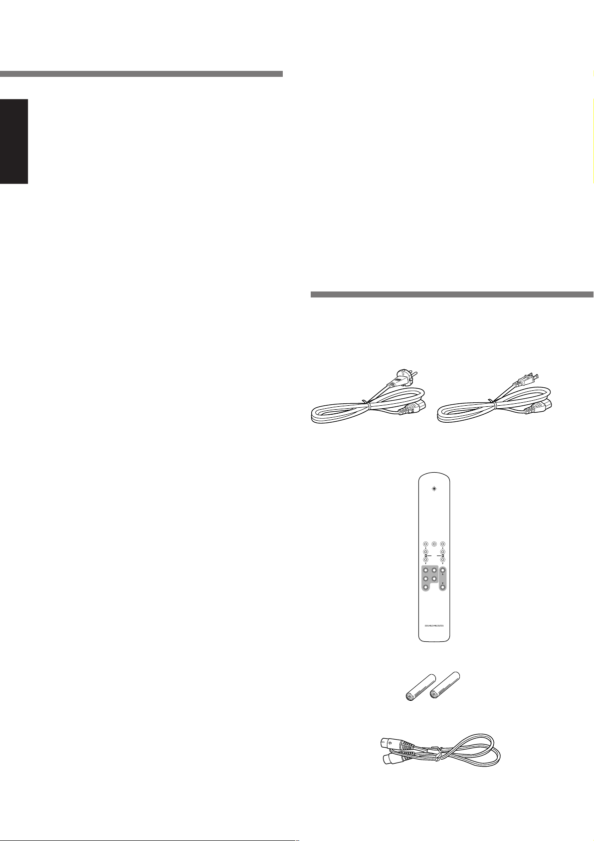
2. Accessaries
After opening the cover of the packing box, check that the
following accessories are included.
●
AC Power Cable
●
General Precautions
When siting the equipment ensure that:
— the ventilation holes are not covered;
— air is allowed to circulate freely around the equipment
— it is on a vibration free-surface;
— it will not be exposed to interference from an external
source;
— it will not be exposed to excessive heat, cold, mois
ture or dust;
— it will not be exposed to direct sunlight;
— it will not be exposed to electrostatic discharges
Never place heavy objects on the equipment.
If a foreign body or water does enter the equipment, contact
your nearest dealer or service centre.
Do not pull out the plug by pulling on the mains lead, hold the
plug.
It is advisable when leaving the house, or during a thunderstorm, to disconnect the equipment from the mains supply.
(Model SC7S1/N1G) (Model SC7S1/U1G)
●
Remote Controller RC-7S1SC
ATTEXITTRIM MODE
TRIM
BA
SACD/CD
BALANCED
LINE 1 LINE 2
VOLUME
TAPE
RC-7S1SC
●
AAA (R03) Batteries
●
Remote Cable
●
Instruction Manual (this Copy)
2
Page 7

3. Main feature of product
●
The concept: channel separation for super
wide range & dynamic audio
We think it’s of the utmost importance to extend high frequency
response as well as channel separation so you can hear the
true meating of “Super Audio.”
This is why we have designed the input and output circuitry,
volume control section, and power supply circuits according
to this philosophy.
The result: an astonishing channel separation of over 100dB
at 20kHz.
●
Fully balanced control amp with an linear
volume control
The SC-7S1 is a full balanced, two-channel control amp providing the channel separation you need for Super Audio.
Based on our own high quality four-gang active volume control we have developed an even better linear control volume
that reduces gang errors from 0 to 100dB, ±0.5dB. By adding an additional HDAM SA (High Definition Amplifier Module), we improved the Common Mode Reject Ratio (CMRR)
dramatically, attaining an incredible ultra-wide frequency band
of 150kHz and succeeded in producing the perfect control
amplifier for Super Audio CD.
●
HDAM SA
The feedback impedance of the Current Feedback circuit was
reduced to its minimum to make it faster. We developed a
new High Definition Amplifier Modules (HDAM), a separeted
module operating as a buffer for the amplifier. The SC-7S1
has four HDAM SA on each input-output buffer and another
four units on the V/I converter.
●
Choke input system
In the power supply section, the choke input topology was
adopted to drastically reduce rectifier harmonic noise. This
system is especially suitable for a control amplifier in which
very small signal amplification occurs.
ENGLISH
●
Floating control bus system
We make it possible to synchronously drive two or more control amps by using a floating control bus system connected
to as many as 6 sets of control amplifiers. We also enable you
to trim levels using the remote control, making it easy to set
up the optimal sound field on a multi-channel configuration.
The highest achievable stereo performance can be accomplished when a system configured with two sets of SC-7S1
and four sets of MA-9S1 are connected in a bi-amped mode.
You will experience superb sound with unbelievable channel
separation.
3
Page 8

ATTENUATOR
dB
UNBALANCED
BALANCED
INPUT
ATTENUATOR
dB
UNBALANCED
BALANCED
INPUT
-
6
3
9
12
0
-
6
3
9
12
0
ID NO.
ID NO.
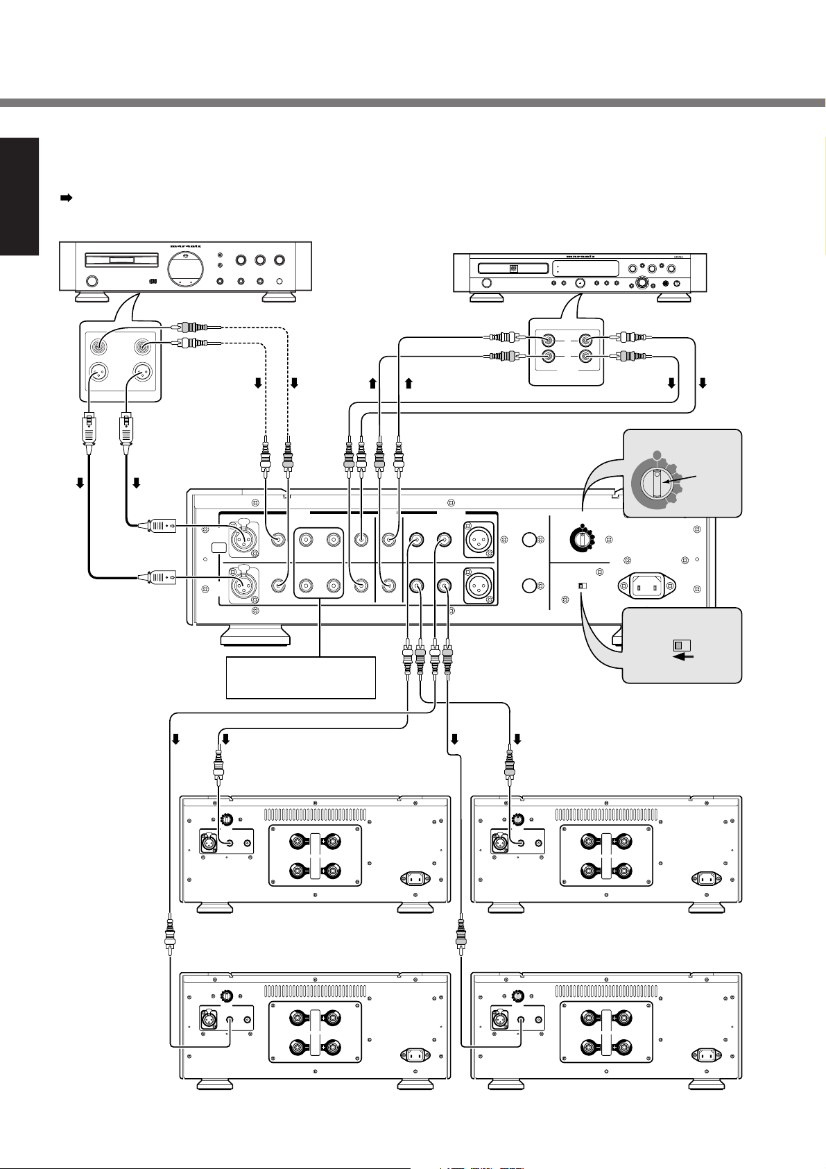
4. Connections
Connection 1 Stereo connection
ENGLISH
:Signalflow
RIGHT
ANALOG
OUTPUTS
UNBALANCED
BALANCED
1 1
SACD Player / CD Player
LEFT
or
SC-7S1
BIAMP
BALANCED
PUSH
PUSH
A
CH
PUSH
PUSH
B
CH
SACD/CD
1 LINE 2
To connect analog output of
FM tuner, VCR.
CD Recorder / Tape Deck
5
4
6
3
7
2
8
1
9
10
POWER
L
R
OUTPUT
INPUT
ANALOG
0
ID NO.
1
2
3
Setting 1
4
5
REC
OUT
TAPE
UNBALANCED
PRE OUTINPUT
BALANCED
21
REMOTE
CONTROL
OUT
ID NO.
IN
2
3
4
5
6
MODE
BI-AMPSTEREO
6
MODE
Setting STEREO
BI-AMPSTEREO
or
MA-9S1
or
MA-9S1
For L ch For R ch
(
)
-
ATTENUATOR
dB
0
--3
--6
--9
--12
-
∞∞
INPUT
BALANCED
UNBALANCED
PUSH PUSH
1 2
1
SPEAKERS
2
This connection can have options i,e, In-between 2 Un-balanced terminals or balanced terminals are
possible to wire SACD/CD and control Amp. And SC-7S1 with MA-9S1.
BALANCED
ATTENUATOR
--6
--9
--12
--3
-
∞∞
INPUT
0
UNBALANCED
1 2
(
)
dB
1
SPEAKERS
2
4
Page 9
Connection 1–4 are recommended by Marantz for SC-7S1 with Marantz MA-9S1.
Please read instruction manual for MA-9S1 in case of use.
Name and Function → P13
Standard set-up in using Marantz Monaural Power Amp MA9S1.
Please refer to this connection in event of using other Power
Amps too.
●
SC-7S1 doesn't have Phono equalizer. So in the event of
using turn table, please use the optional Phono equalizer
to wire with SC-7S1.
●
SC-7S1 has function on in/output terminal with upper "A
ch", lower "B ch".
●
In event that stereo L ch signal has been wired with A ch
input, the signal will be come out to the pre-out of A ch.
Please pay attention to L ch, R ch if SC-7S1 is wired with
the other equipment.
4. Connections
ENGLISH
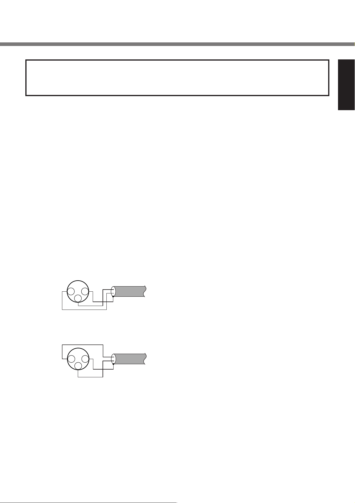
■ Balanced terminal
q The balanced output connector uses a XLR connector.
w The XLR connector for professional use is internally wired
in either of the following two systems.
1. USA system (Pin 2 = COLD, Pin 3 = HOT)
COLD
21
HOT
2. European system (Pin 2 = HOT, Pin 3 = COLD)
21
HOT
COLD
e The SC-7S1 uses the USA system of 1.
When a preamp or main amplifier adopting the European
system is connected using a cable with XLR balanced
connectors, the reproduced signal may be inverted of
phase.
In this case, correct the wiring of the one of the XLR connectors on the extremities of the cable to the USA system
by exchanging the connections of pins 2 and 3. This will
make it possible to play the signal with the correct phase.
GND
3
GND
3
5
Page 10
ATTENUATOR
dB
UNBALANCED
BALANCED
INPUT
ATTENUATOR
dB
UNBALANCED
BALANCED
INPUT
-
6
3
9
12
0
-
6
3
9
12
0
ATTENUATOR
dB
UNBALANCED
BALANCED
INPUT
ATTENUATOR
dB
UNBALANCED
BALANCED
INPUT
-
6
3
9
12
0
-
6
3
9
12
0
ID NO.
ID NO.
4. Connections
Connection 2 Bi-Amp connection
ENGLISH
:Signalflow
(Speaker system needs to comply with Bi-Amp connection)
RIGHT
ANALOG
OUTPUTS
UNBALANCED
BALANCED
1 1
SACD Player / CD Player
LEFT
or
SC-7S1
BIAMP
BALANCED
PUSH
PUSH
A
CH
PUSH
PUSH
B
CH
SACD/CD
1 LINE 2
To connect analog output of
FM tuner, VCR.
CD Recorder / Tape Deck
5
4
6
3
7
2
8
1
9
0
POWER
10
L
R
OUTPUT
INPUT
ANALOG
ID NO.
1
2
3
Setting 1
4
5
REC
OUT
TAPE
UNBALANCED
PRE OUTINPUT
BALANCED
21
REMOTE
CONTROL
ID NO.
MODE
2
3
4
5
6
IN
OUT
BI-AMPSTEREO
6
MODE
BI-AMPSTEREO
Setting STEREO
MA-9S1 MA-9S1
For L ch MF/HF For R ch MF/HF
(
)
-
ATTENUATOR
dB
0
--3
--6
--9
--12
-
∞∞
INPUT
BALANCED
UNBALANCED
PUSH PUSH
1 2
1
SPEAKERS
2
BALANCED
ATTENUATOR
--6
--9
--12
--3
-
∞∞
INPUT
0
(
)
dB
UNBALANCED
1 2
1
SPEAKERS
2
MA-9S1 MA-9S1
For L ch For R ch
(
)
-
ATTENUATOR
dB
0
--3
--6
--9
--12
-
∞∞
INPUT
BALANCED
UNBALANCED
PUSH PUSH
1 2
1
SPEAKERS
2
BALANCED
ATTENUATOR
--6
--9
--12
--3
-
∞∞
INPUT
0
(
)
dB
UNBALANCED
1 2
1
SPEAKERS
2
6
Page 11

4. Connections
This connection can have options i,e, In-between 2 Un-balanced terminals or balanced terminals are
possible to wire SACD/CD and control Amp.
Please select either way of connection.
Enhance the connection 1 to Bi-Amp connection, and drive
Low speaker unit and Mid/High speaker unit by respective
power Amplifiers.
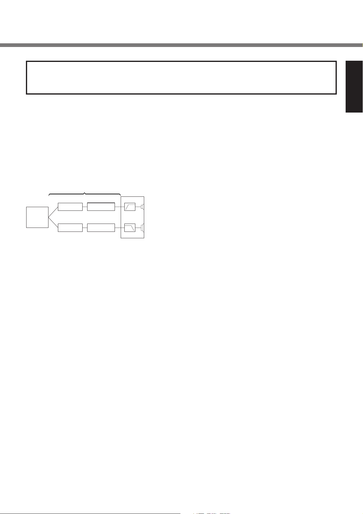
■ Bi-Amp (connection)
The wiring method enhanced from Bi-Wiring, drive Low
speaker unit and Mid/High speaker unit by respective power
Amplifiers. Bi-Amp will lessen the burden on Power Amp impedance, so that back electromotive force between Low and
Mid/High signal can be lessen, we can expect drastic improvement on sound quality.
ENGLISH
CD Player
Bi-Amp connection
Power-Amp
Pre-Amp
Power-Amp
Speaker system
Mid/High
speaker unit
Low speaker
unit
Caution
In the event of this connection (Control Amp SC-7S1 is
<Stero>mode), SC-7S1 and MA-9S1 can be wired by
Unbalanced connection only.
7
Page 12
ATTENUATOR
dB
UNBALANCED
BALANCED
INPUT
-
6
3
9
12
0
ATTENUATOR
dB
UNBALANCED
BALANCED
INPUT
-
6
3
9
12
0
REMOTE
CONTROL
PRE OUT
INPUT
REC
OUT
BI-AMP
STEREO
ID NO.
ATTENUATOR
dB
UNBALANCED
BALANCED
INPUT
-
6
3
9
12
0
ATTENUATOR
dB
UNBALANCED
BALANCED
INPUT
-
6
3
9
12
0
REMOTE
CONTROL
PRE OUT
INPUT
OUT
AMP
BI-AMP
STEREO
ID NO.
ID NO.
ID NO.
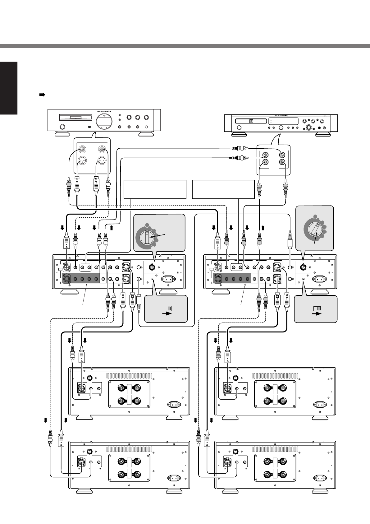
4. Connections
Connection 3 Complete Bi-Amp connection
ENGLISH
:Signalflow
(Speaker system needs to comply with Bi-Amp connection)
SACD Player / CD Player
CD Recorder / Tape Deck
5
4
6
3
7
2
8
1
9
10
POWER
0
ANALOG
OUTPUTS
UNBALANCED
LEFT
RIGHT
L
BALANCED
1 1
To connect analog output
Lch of FM tuner, VCR.
To connect analog output
Rch of FM tuner, VCR.
INPUT
ANALOG
R
OUTPUT
ID NO.
ID NO.
1
REMOTE
CONTROL
2
3
Setting 1
4
5
6
INPUT
BALANCED
ID NO.
1
2
IN
3
4
5
6
OUT
MODE
BI-AMP
STEREO
MODE
A
CH
BIAMP
B
CH
SC-7S1
FOR R ch
BI-AMPSTEREO
PUSH
PUSH
PUSH
PUSH
SACD/CD
Bch can't
be used.
1 LINE 2
TAPE
REC
PRE OUT
OUT
UNBALANCED
21
REMOTE
BALANCED
CONTROL
IN
OUT
or or
REC
INPUT
BALANCED
1 LINE 2
SACD/CD
PUSH
PUSH
A
CH
BIAMP
PUSH
PUSH
B
CH
SC-7S1
For L ch
Bch can't
be used.
TAPE
PRE OUT
OUT
UNBALANCED
BALANCED
21
Setting BI-AMP
1
Setting 2
ID NO.
1
2
3
4
5
6
MODE
BI-AMP
STEREO
MODE
Setting BI-AMP
2
3
4
5
6
BI-AMPSTEREO
oror
MA-9S1 MA-9S1
For L ch MF/HF For R ch MF/HF
(
)
-
ATTENUATOR
dB
0
--3
--6
--9
--12
-
∞∞
INPUT
BALANCED
UNBALANCED
PUSH
1 2
SPEAKERS
1
2
BALANCED
(
)
-
ATTENUATOR
dB
0
--3
--6
--9
--12
-
∞∞
INPUT
UNBALANCED
PUSH
1 2
1
SPEAKERS
2
or or
MA-9S1 MA-9S1
For L ch For R ch
(
)
-
ATTENUATOR
dB
0
--3
--6
--9
--12
-
∞∞
INPUT
BALANCED
UNBALANCED
PUSH
1 2
SPEAKERS
1
2
BALANCED
(
)
-
ATTENUATOR
dB
0
--3
--6
--9
--12
-
∞∞
INPUT
UNBALANCED
PUSH
1 2
1
SPEAKERS
2
8
Page 13
4. Connections
This connection can have options i,e, In-between 2 Un-balanced terminals or balanced terminals are
possible to wire SACD/CD and Control Amp. And Contol Amp with Power Amp.
Select either way of connection.
■ Complete Bi-Amp connection
Enhance the connection 2, by having one more control Amp.
SC-7S1, this is a wiring <Complete Bi-Amp connection> which
separates Mid/High (MF/HF) signal and Low (LF) signal from
Pre-Amp section. In this event, SC-7S1 is used as Monaural
Amps. And separate Left/Right channels from output terminal of CD players. As a result, influences between L channel
and R channel Mid/High signal and Low signal will be eliminated.
ENGLISH
CD Player
Complete Bi-Amp connection
Pre-Amp
Pre-Amp
Power-Amp
Power-Amp
Speaker system
Mid/High
speaker unit
Low Speaker
unit
By connection with remote cabel, maiximamly 6 pcs can be
interlock operated.
Caution
In the event of setting mode switch as <Bi-Amp>, B channel input can't be used.
9
Page 14
4. Connections
■ Installing the SACD multi-channel
ENGLISH
audio speakers
In order to enjoy SACD multi-channel sound with the best
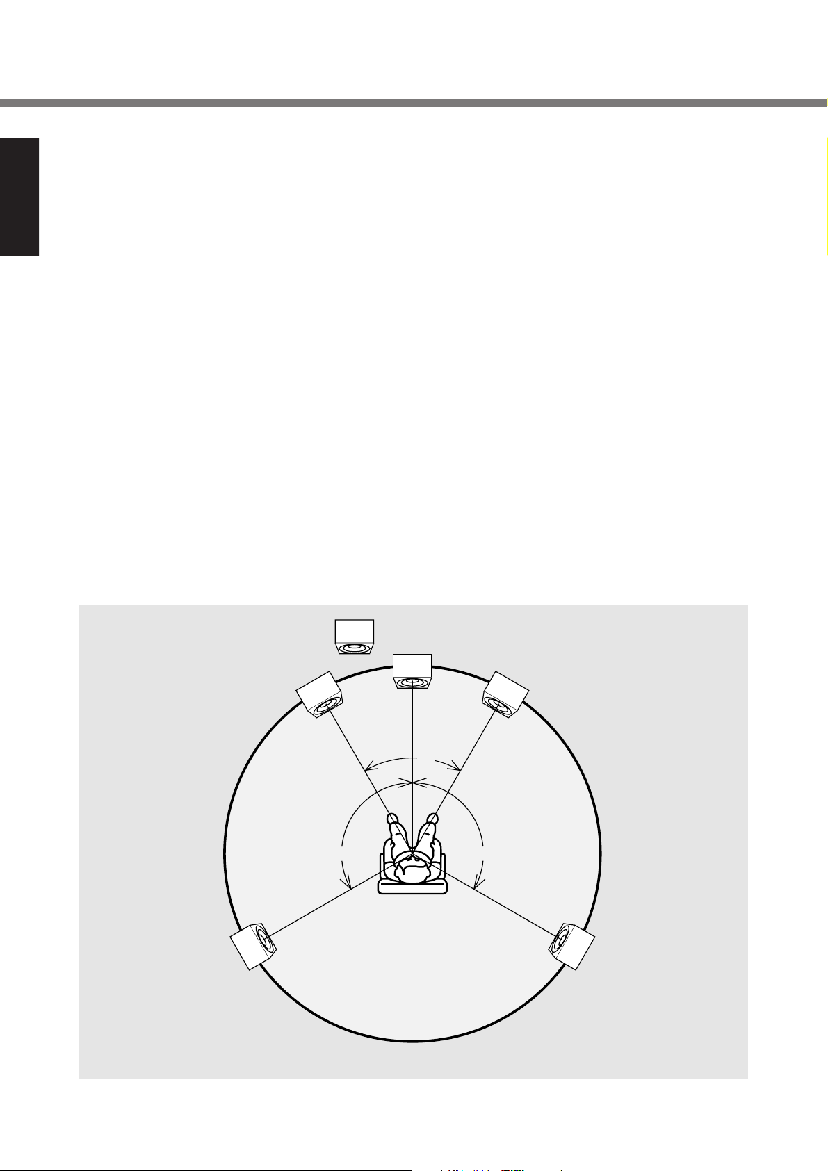
possible acoustics, it is recommended that the speaker systems be laid out in compliance with the ITU-R BS.775-1 recommendation which is a standard formulated by the International Telecommunication Union (ITU).
SACD multi-channel discs are recorded and mixed in such a
way that they will achieve the optimum effects when the
speaker systems are laid out as per the ITU-R BS.775-1 recommendation.
• On SACD multi-channel discs, the music signals are basically recorded using 5 channels (or 3, 4 or 6 channels
in some cases). In some instances, however, LFE (for
the sub woofer) is recorded as a sixth channel.
Each disc indicates how many channels have been recorded on it.
• The basic settings are 3 speakers for front and 2 for back
since multi-channel discs have basically 5 channels
The 2-front, 1-center, and 2-surround speakers should
be set on the circle from the listening point as shown
below.
When you use different sizes of speakers, please adjust
the volume balances.
• The location of the sub-woofer in the picture is just to you
a patter of settings. Sub-woofer can be located any place
in your room. (See the users manual of your sub-woofer.)
■
(ITU) International Telecommunication
Union
The ITU is a special organization of the United Nations. It
consists of a number of organs, one of which is the Radio
Broadcasting Section.
ITU-R BS in the recommendation which consists of standards
relating to broadcasting (audio) operations, one of which is
the ITU-R BS.775-1 which governs “multi-channel stereo
sound systems.”
Front speaker
Rear speaker
(Left Surround)
Sub-woofer
(Left)
approx. 110° approx. 110°
Center
speaker
60°
Reference listening
position
Front speaker
(Right)
Rear speaker
(Right Surround)
10
Page 15
ATTENUATOR
(
dB
)
UNBALANCED
BALANCED
INPUT
12
SPEAKERS
2
1
-
∞
-
6
-
3
-
9
-
12
0
PUSH
ATTENUATOR
(
dB
)
UNBALANCED
BALANCED
INPUT
12
SPEAKERS
2
1
ATTENUATOR
(
dB
)
UNBALANCED
BALANCED
INPUT
12
SPEAKERS
2
1
-
∞
-
6
-
3
-
9
-
12
0
-
∞
-
6
-
3
-
9
-
12
0
PUSH PUSH
ATTENUATOR
(
dB
)
UNBALANCED
BALANCED
INPUT
12
SPEAKERS
2
1
ATTENUATOR
(
dB
)
UNBALANCED
BALANCED
INPUT
12
SPEAKERS
2
1
-
∞
-
6
-
3
-
9
-
12
0
-
∞
-
6
-
3
-
9
-
12
0
PUSH PUSH
POWER
STANDBY
For front
L ch / R ch
MA-9S1
For L ch
SC-7S1
For front center
Sub Woofer
SC-7S1
For Sorround
L ch / R ch
SC-7S1
REMOTE
CONTROL
PRE OUTINPUT
BALANCED
REC
OUT
TAPE
1LINE2
SACD/CD
BALANCED
A
BIAMP
21
UNBALANCED
IN
OUT
MODE
BI-AMPSTEREO
6
5
4
3
2
CH
B
CH
PUSH
PUSH
ID NO.
PUSH
PUSH
1
REMOTE
CONTROL
PRE OUTINPUT
BALANCED
REC
OUT
TAPE
1 LINE 2
SACD/CD
BALANCED
A
BIAMP
21
UNBALANCED
IN
OUT
MODE
BI-AMPSTEREO
6
5
4
3
2
CH
B
CH
PUSH
PUSH
ID NO.
PUSH
PUSH
1
REMOTE
CONTROL
PRE OUTINPUT
BALANCED
REC
OUT
TAPE
1 LINE 2
SACD/CD
BALANCED
A
BIAMP
21
UNBALANCED
IN
OUT
MODE
BI-AMPSTEREO
6
5
4
3
2
CH
B
CH
PUSH
PUSH
ID NO.
PUSH
PUSH
1
FRONT R FRONT L SURROUND R SURROUND L SUB-WOOFER
MULTI CHANNEL AUDIO OUT
CENTER
MA-9S1
For R ch
MA-9S1
For front center ch
MA-9S1
For surround L ch
MA-9S1
For surround R ch
MODE
Setting 1
6
5
4
3
2
ID NO.
1
BI-AMPSTEREO
Setting STEREO
MODE
BI-AMPSTEREO
Setting STEREO
MODE
BI-AMPSTEREO
Setting STEREO
6
5
4
3
2
ID NO.
1
Setting 3
6
5
4
3
2
ID NO.
1
Setting 2
ororor or
Active (Powered)
Sub-Woofer
or
:Signal flow
SACD Multi Channel Player etc.
4. Connections
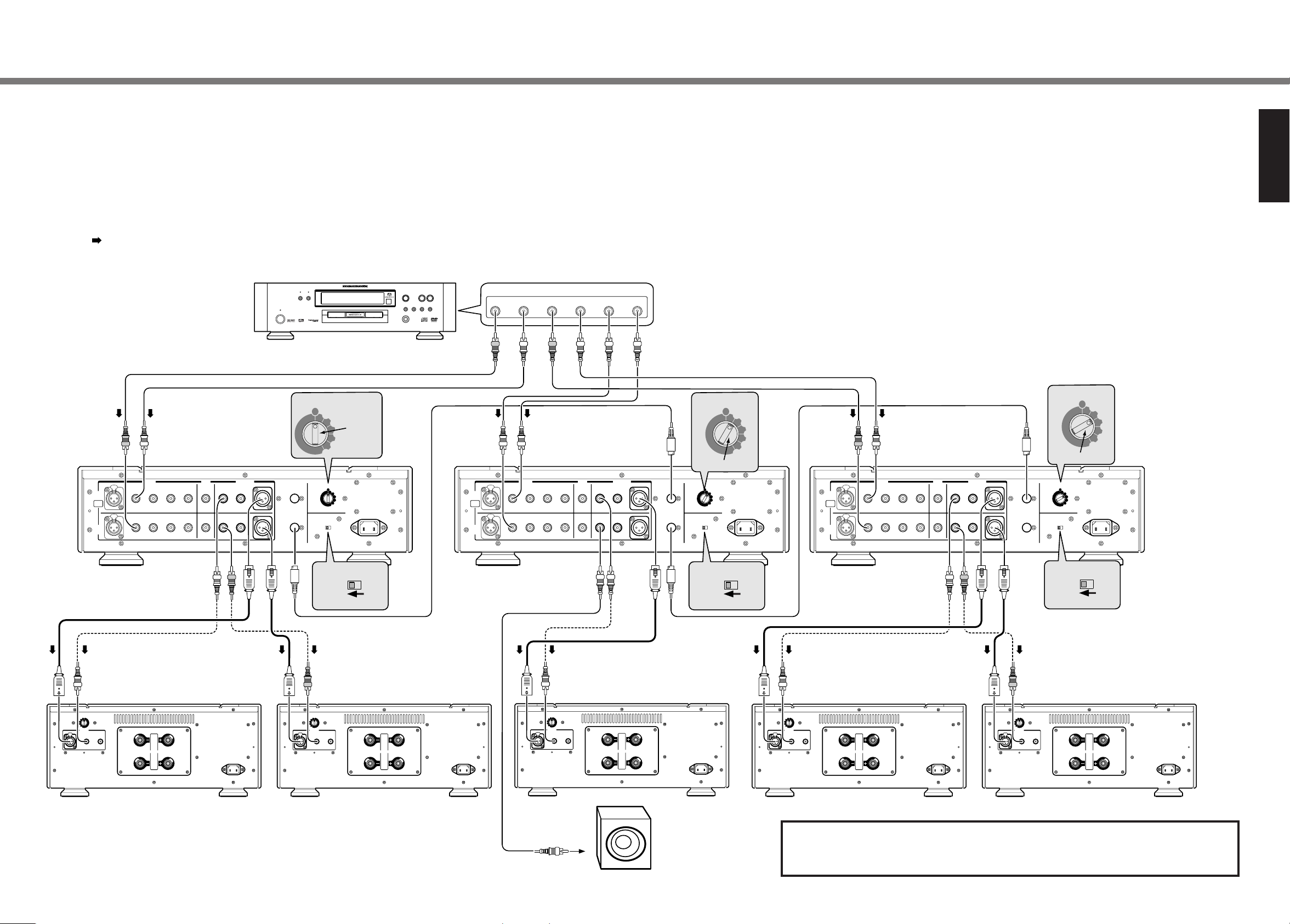
Connection 4 5.1ch multi-channel connection This Connection is standard for Multi-channel sound source. Realize the high quality sound acoustic for the professional Home
theatre and pure multi channel SACD. The whole system 5.1 ch is controlled by 3 units of SC-7S1 connected operation.
The system can be enhanced to
●
<3 units of SC-7S1 + 10 units of MA-9S1 + Active sub-woofer>
●
<6 units of SC-7S1 + 10 units of MA-9S1 + Active sub-woofer>
Caution
●
In case Active (powered) sub-woofer is used for LFE, please set-up wiring after perusal of Instruction manual.
LFE (Low frequency Effect) is the channel for Low Frequency only.
●
In case Passive sub-woofer is used for LFE, Monaural power Amp such as MA-9S1is required to drive it.
ENGLISH
This connection style can have options i,e, In-between 2 Un-balanced terminals or
balanced terminals to wire Control Amp. and Power Amp.
Select either way of connection.
11
Page 16
5. Name and funtion
BALANCED
SACD
/
CD
LINE 1
DISPLAY
ATT
LINE 2
TAPE
A
SYNC B
input selector
power
stereo
control amplifier sc-7s1
volume
q
r
uw yte
A
SYNC B
I
II
IIIIV
max.
min.
00.0dB
-0.5dB
-1.0dB
-99.0dB
-99.5dB
-100.0dB
-∞
0.5 dB step
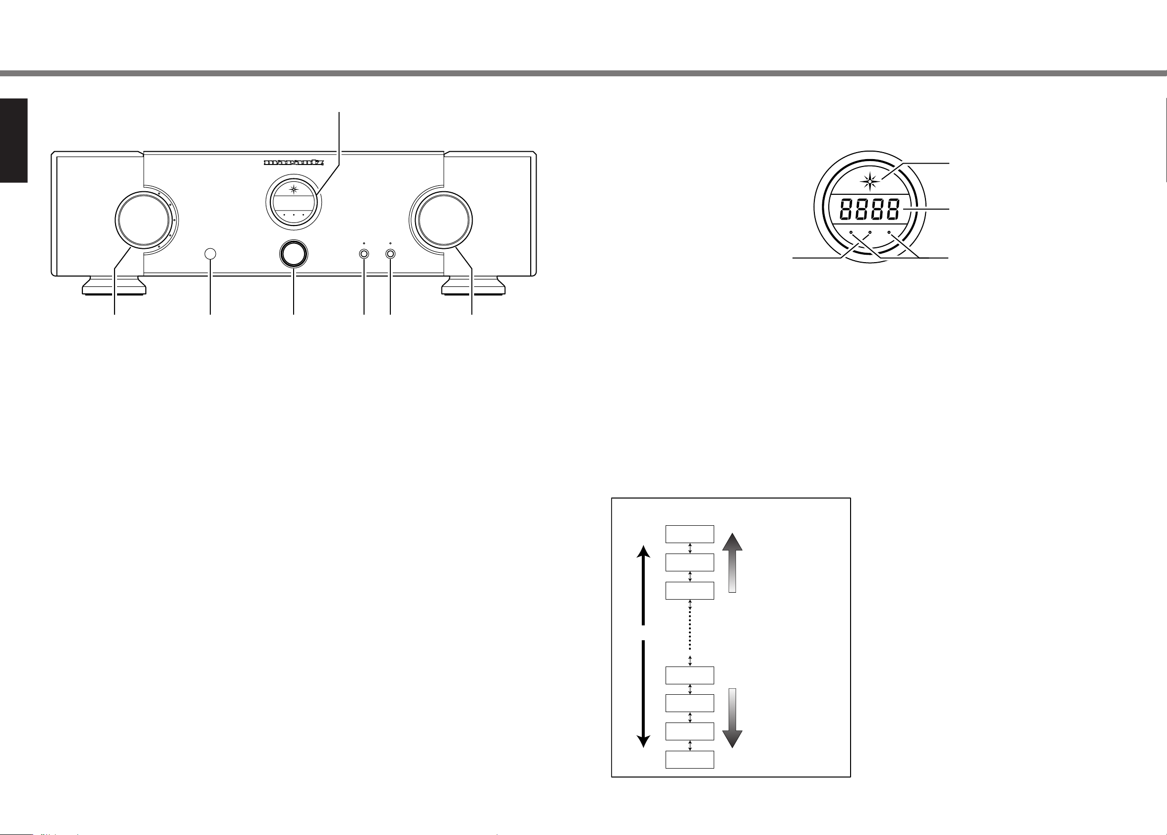
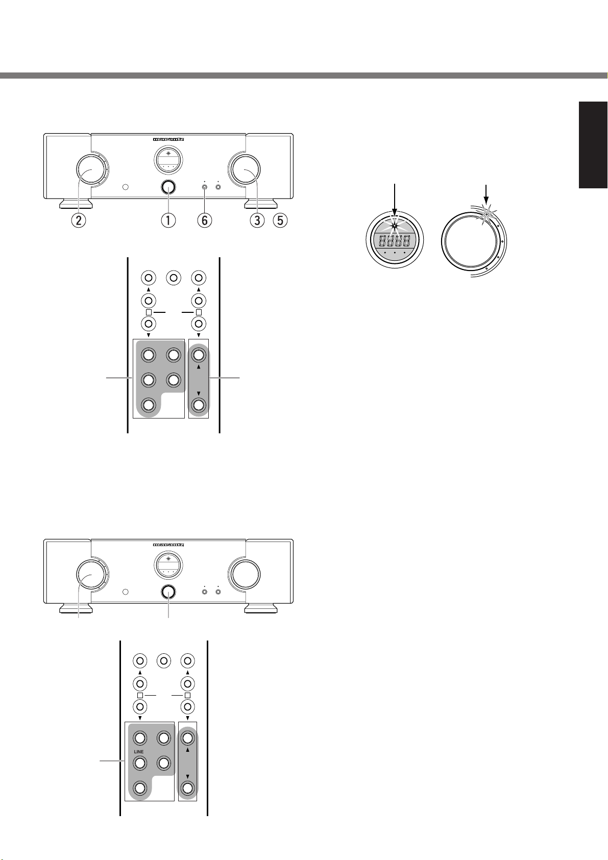
Front panel
ENGLISH
q Power switch
The switch to on/off the power. Press the switch, the power is
on, and indicator of input selector will light-on for source selected. SC-7S1 is ready approx. 8 sec. after power on. If
switch is pressed while power on, the power will be off and
indicators will be light-off.
w Remote control sensor
This is the window to receive control signal being sent from
remote controller.
How to use remote controller → p.14
e Input selector knob
The input selector knob to select input source for record/play.
Blue indicator is light on.
The last selected input source will be memorized before
switched off, and it will remain selected when switch is on
again. If the tape is selected as input source, the signal will
not be output to Rec out terminal.
r Display section
Indicate the setting status, volume level on this displayed.
12
Display section
t Volume knob
The knob to adjust volume.
Turning clockwise to volume up, counterclockwise to volume
I Power indicator
Indicator to show if power is on. When power is on, the blue
light will be turn on.
down. By turning knob slowly, the volume will be varied by
0.5dB step. By turning knob quickly, the variance will be bigger. The last volume setting will be memorized before switched
off, and it will remain selecetd when switch is on again.
II Volume indicator
Indication of volume operated by remote controller or button.
3 second after the power is on, ID number which is set up by
ID no switch on rear. Then the volume is indicated by decay
y ATT (Attenuation) button, indicator
level.
The button to control volume at one touch. Once the button is
pressed, the volume will be decayed and volume indication
will be blinking and indicator above button will light on. If the
button is pressed once again, volume indication will turn back
the status before the button is not pressed.
Decay level is fixable to any of -20dB, -40dB, -60dB, -∞.
Attenuation function → p16
Turn clockwise the volume
u Display button, indicator
The button to on-off the volume indicator and internal light.
knob or press volume ▲
button of Remote.
Once the button is pressed, the volume indicator and internal
light will be off and indicator above button will be light on. If
the front button is operated, volume indicator and internal light
will be light on in 3 second, and turn off again.
The button is pressed once again, volume indicator and internal light will be light on again, the indicator above button
will be turn off.
Turn counterclockwise the
volume knob or press volume ▼ button of Remote.
In case the attenuate function is used or trim adjustment is
made, setting level will be indicated.
Error code will be indicated if there is error on connection,
settings while several SC-7S1 are connected.
Error message → p20
III A/B CH Indicator
During trim adjustment, the indicator will be light on in accordance with adjusting channel.
Trim adjustment → p17
IV SYNC (Synchronized) Indicator
The indicator will be light on in accordance with ID number
setting or so on.
●
Green colour is light on:
ID No. is set up <1>.
●
Red colour is light on:
ID No. is set up 2–6 (several SC-7S1 are connected)
Operation by product or Remote controller will not be received.
●
Light off:
There is some error in remote connection.
●
Green or Red colour is flashed:
While trim is being adjusted.
When you use remote controller, please face it towards SC-7
while this indicator turns light or flashing in green.
Page 17
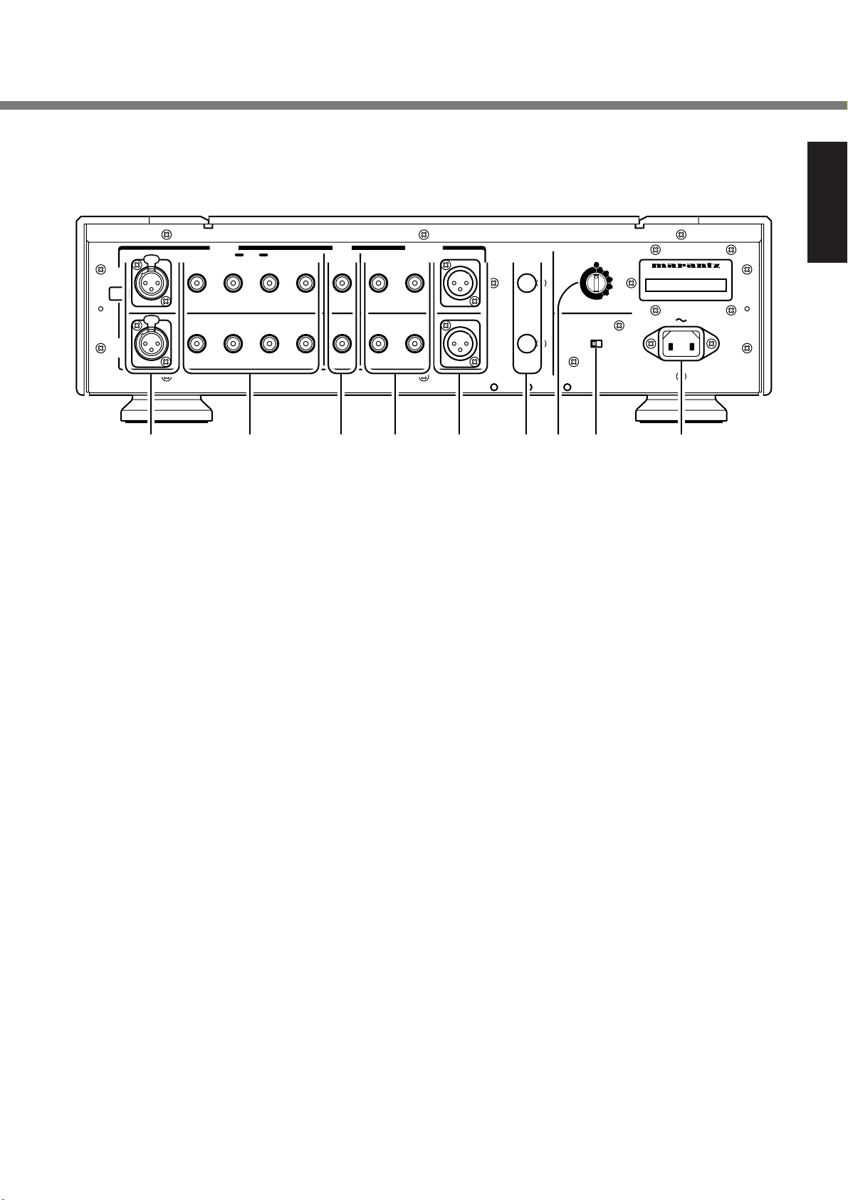
Rear panel
ID NO.
5. Name and funtion
TAPE
REC
OUT
UNBALANCED
A
CH
BIAMP
B
CH
BALANCED
PUSH
PUSH
PUSH
PUSH
SACD/CD
1 LINE 2
z bvc n , .mx
z Input Balanced terminal
The terminal to connect with balanced output terminal of
SACD, CD Players.
In case of Bi-Amp mode, Input terminal of B Channel can not
be used.
Balanced terminal → p5
x Input SACD/CD, Line 1, Line 2, Tape (Un-
balanced) terminal
The terminal to connect with output terminal of SACD, CD
Players.
In case of Bi-Amp mode, Input terminal of B Channel can not
be used.
c Rec out terminal
The terminal to connect with input terminal of Recording equipment such as CD recorder.
In case of Bi-Amp mode, the signal input to A channel will be
out to both of A/B channels.
v Pre out Unbalanced 1,2 terminal
The terminal to connect with Unbalanced input terniminal of
Power Amp.
In case of Bi-Amp mode, the signal input to A channel will be
out to both of A/B channels.
PRE OUTINPUT
21
BALANCED
BALANCED
CONNECTION1
REMOTE
CONTROL
OUT
COLD2
ID NO.
1
3 HOT
MODE
(
)
+
2
3
4
5
6
AC IN
BI-AMPSTEREO
IN
(-)
COLD
n Remote control In/Out terminal
To connect several units of SC-7S1 by attached remote cable,
and connectedly operate them.
In terminal is for receiving control signal, Out terminal is for
sending control signal.
m ID No. switch
Whilst several SC-7S1 are connected, to set up respective ID
No. to distinguish each products.
When only 1 unit is used, the No. will be set 1. Initial setting is
<1>.
Trim adjustment in case of several units of SC-7S1 → p18
, Mode switch
The switch to change Stereo mode and Bi-Amp mode. Initial
setting is <stereo>.
●
In case SC-7S1 is used by normal 2 channel.
Setting <Stereo> mode.
●
In case of complete Bi-Amp connection by 2 units of SC7S1.
Setting <Bi-Amp> mode.
In case of <Bi-Amp> mode, the signal input from A channel will be out to both of A/B channels through Pre-out
terminal and Rec out terminal.
Then, input terminal on B channel can not be used.
ENGLISH
b Pre out Balanced terminal
The terminal to connect Balanced input terminal of Power
Amp.
In case of Bi-Amp mode, the signal input to A channel will be
out to both of A/B channels.
. AC IN socket
Connect to a household power outlet.
13
Page 18
5. Name and funtion
Remote controller
ENGLISH
a
f
h j
BALANCED
LINE 1 LINE 2
TAPE
TRIM
SACD/CD
ATTEXITTRIM MODE
VOLUME
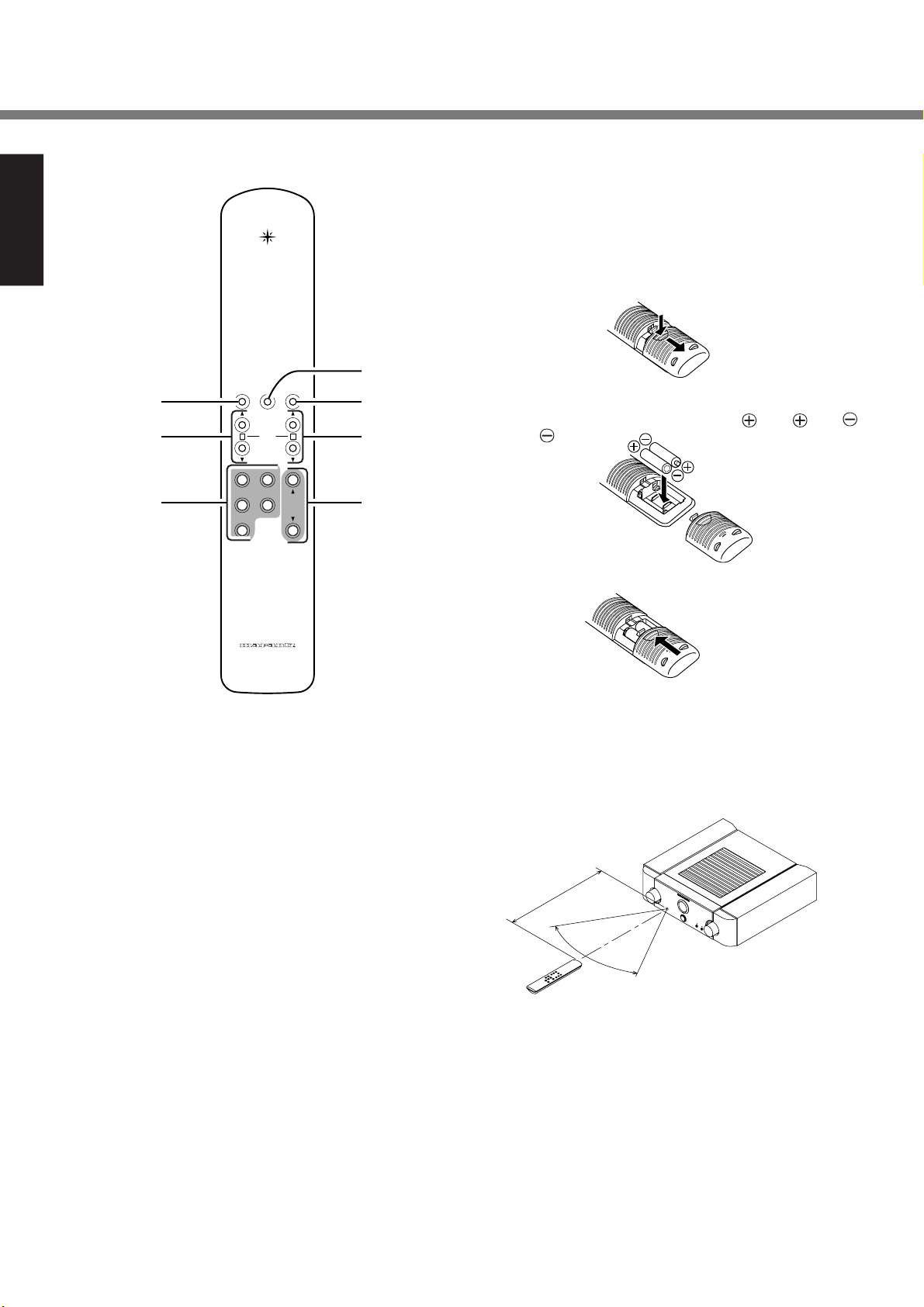
■ For use of Remote controller
●
Loading batteries
Before using the supplied remote control unit for the first
time, load the batteries in the remote control unit. The
batteries provided are used to verify the operations of the
remote control unit only.
1 Remove the battery cover which is found on the back
side of the remote control unit.
s
2 Load the two new size “AAA” batteries inside the battery
d
BA
g
compartment while taking care to align their polarities
correctly with the polarity markings (
with ).
with and
3 Push the cover on the back side in the direction of the
arrow to close.
RC-7S1SC
a Trim Mode
Button to switch to Trim mode for trim adjustment.
s Exit button
Button to finish Trim mode after Trim adjustment.
d ATT (Attenuation) button
Button to attenuate at one touch.
f Trim-A ▲/▼
(Trim A Channel up/down) button
Button to fine-tune the output level of A ch by Trim adjustment.
g Trim-B ▲/▼
(Trim B Channel up/down) button
Button to fine-tune the output level of B ch by Trim adjustment.
h Input selector button
Button to select input source.
j Volume ▲/▼
(Volume up/down button)
Button to adjust volume.
14
●
Operatable range of Remote controller
Operate the remote control unit (RC-7S1SC) within a distance of approx. 5 m from the infrared signal reception
window (remote sensor) on the front of the SC-7S1.
Remote control operation may not be possible if the remote control unit’s transmitter is not pointing in the direction of the remote sensor or if there is an obstruction between the transmitter and the remote sensor.
Approx. 5m
60°
●
Caution
Do not allow direct sunlight, an inverter fluorescent light
or other strong source of light to shine onto the player’s
infrared signal reception window (remote sensor). Otherwise, the operation of the remote control unit may be disabled.
Bear in mind that operating the remote control unit may
cause other devices operated by infrared rays to be operated by mistake.
The remote control unit cannot be operated if the space
between the controller and the player’s remote sensor is
obstructed.
Do not place any objects on top of the remote control
unit. Doing so may cause one or more buttons to be held
down which will cause the batteries to run down.
Page 19
input
selector
power
stereo
control
amplifier
volume
input
selector
power
stereo
control
amplifier
volume
6. Standard operation
■ How to Play
BALANCED
SACD
/
CD
LINE 1
LINE 2
TAPE
input
selector
w
stereo
control
A
qy etw
BALANCED
LINE 1 LINE 2
TAPE
amplifier
SYNC B
power
TRIM
SACD/CD
q Power on SC-7S1. In case several SC-7S1 are con-
nected, please power on from smaller No. of ID to bigger
No.
sc-7s1
Once power is on, Front display and input indicator for
currently selected source will be light on.
ATT
DISPLAY
volume
ATTEXITTRIM MODE
POWER
Indicator
SYNC B
A
Input Source
Indicator
BALANCED
TAPE
ENGLISH
SACD
/
CD
LINE 1
LINE 2
Approx. 8 second after power on, the Sound will be mute
BA
mode and released later.
w Select the input source by input selector button or Input
select button on the Remote controller.
e It is recommended to power on after setting volume to -
by the button of ▲/▼ of volume button or Remote controller.
VOLUME
et
r Play music by operating equipments such as CD Play-
ers.
t Adjust the volume by the button of ▲/▼ of SC-7S1 or
Remote controller.
y If the display button is pressed, the volume indicator will
be turn off.
■ How to record
BALANCED
/
CD
SACD
LINE 1
LINE 2
TAPE
input
selector
BALANCED
LINE 1 LINE 2
w
TAPE
stereo
control
TRIM
SACD/CD
q Power on SC-7S1.
w Select the input source by input selector button or Input
select button on the Remote controller.
amplifier
sc-7s1
e Play music by operating equipments such as CD Play-
ers.
SYNC B
A
ATT
power
DISPLAY
volume
r Record music by operating recorder such as CD-R which
is connected to Rec out terminal.
If <Tape> is selected for input souce, music can not be
recorded. It's because the analog signal is not output to
Rec out terminal.
qw
ATTEXITTRIM MODE
BA
VOLUME
15
Page 20
7. How to operate function and how to set up
volume
volume
volume
volume
volume
-40dB
-60dB
-∞
-20dB
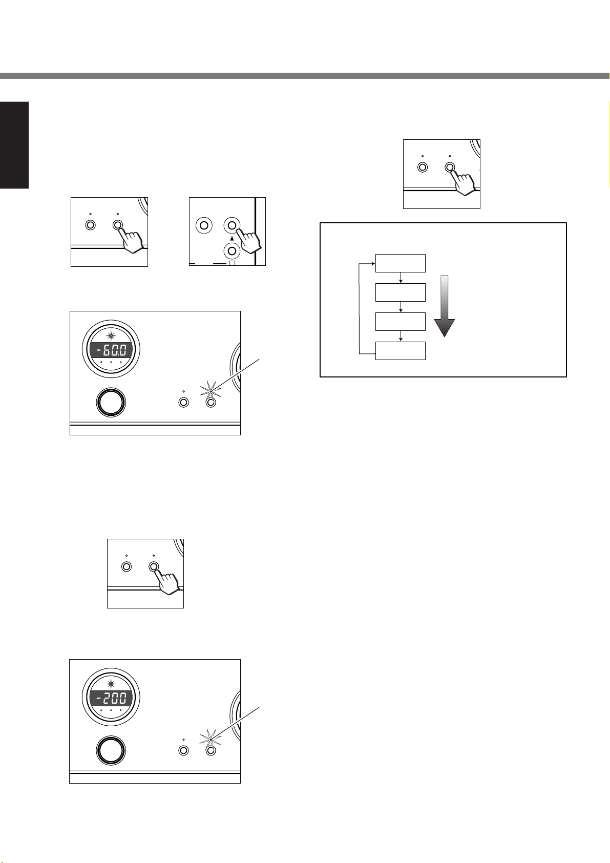
■ Attenuate function
ENGLISH
With one touch, the volume can be down. Convenient when
you want volume down quickly.
ATT button on SC-7S1 or Remote controller can decay volume.
DISPLAY
Unit
ATT
Remote Controller
or
Then volume is indicated, the indicator above ATT button will
be light on.
control amplifier sc-7s1
stereo
SYNC B
A
power
DISPLAY
ATT
e Press ATT button, attenuation level will be changed ev-
ery each press.
DISPLAY
ATTEXIT
ATT
Attenuat function Setting of level
Press ATT button
Light
r Unless the button is pressed within 2 seconds, attenua-
tion level will be fixed. Once the level is fixed, the indication will turn back to volume indication.
Initial set up is -20dB, you can change to -20dB, -40dB,
-60dB, - .
In case of - , attenuator doesn't work.
■ How to set up attenuation level
q Press ATT button more than 2 second.
DISPLAY
w Indicator above ATT button will flash, volume indication
will be changed to attenuation level setting.
control amplifier sc-7s1
stereo
SYNC B
A
power
ATT
Flash
DISPLAY
ATT
The setting of level is memorized even after power off, remain
until power on again.
16
Page 21

7. How to operate function and how to set up
■ Trim adjustment function
Can adjust output level within -6.0dB–+6.0dB (0.5dB step)
by channel.
●
How to adjust Trim setting
In case of 1 unit of SC-7S1
q Press Trim mode button on Remote controller.
Then A ch indicator on Front display section will light on
red, Green coloured Sync indicator will turn to flashing.
Volume indicator will show Trim adjustment level on A ch.
stereo control amplifier sc-7s1
EXITTRIM MODE
SYNC B
A
Light Red
w Once Trim-A button ▲ on Remote controller is pressed,
Trim adjustment level will be increased by 0.5 dB step,
the output level on A ch will be increased.
stereo control amplifier sc-7s1
Flash Green
e Once Trim-B button ▲ or ▼ on Remote controller is
pressed, Indicator on A ch will be turned off, indicator on
B ch will be light on. Then Sync indicator remains flashing Green.
stereo control amplifier sc-7s1
BTRIM
SYNC B
A
Flash Green
Light Red
Volume indicator will show Trim level on B ch.
Once Trim-B button ▲ on Remote controller is pressed,
Trim adjustment level will be increased by 0.5 dB step,
the output level on B ch will be increased.
stereo control amplifier sc-7s1
B
RIM
Flash Green
SYNC B
A
Light Red
ENGLISH
A TRIM
Light Red
SYNC B
A
Flash Green
Once Trim-A button ▼ on Remote controller is pressed,
Trim adjustment level will be decreased by 0.5 dB step,
the output level on A ch will be decreased.
stereo control amplifier sc-7s1
A TRIM
SYNC B
BALANCED
SACD/CD
Light Red
A
Flash Green
Once Trim-B button ▼ on Remote controller is pressed,
Trim adjustment level will be decreased by 0.5 dB step,
the output level on B ch will be decreased.
stereo control amplifier sc-7s1
IM
B
SYNC B
D/CD
Flash Green
A
Light Red
r If the Trim adjustment has been completed, press Exit
button on Remote controller and finish Trim mode.
ATTEXITRIM MODE
17
Page 22

7. How to operate function and how to set up
ID NO.
AC IN
ID NO.
AC IN
In case of 1 several units of SC-7S1
ENGLISH
Set up ID numbers to respective SC-7S1 to extinguish each
of SC-7S1s.
q Set up ID No. switch <1> for main unit of SC-7S1 to con-
trol others, which is called <Master> unit.
The ID No. set up will be indicated for 3 seconds when
power is on.
stereo control amplifier sc-7s1
ID NO.
1
2
3
4
5
6
A
SYNC B
Light Green
w Set up other SC-7S1s which should be connectedly op-
erated by Master as ID No. <2>–<6>.
They are called <Slave> unit.
The ID No. set up will be indicated for 3 seconds when
power is on.
stereo control amplifier sc-7s1
ID NO.
1
2
3
4
5
6
A
SYNC B
t Please refer to p.17 for Terim adjustment as the same
method as 1 unit of SC-7S1.
If the whole system consist of more than 3 units, please
repeat the same procedure and set up remaining units.
Every pressing the Trim mode button, turn to smaller ID
number of SC-7S1 for adjustment.
y If the Trim adjustment is completed for all units, press
Exit button on Remote controller, and finish Trim mode.
ATTEXITRIM MODE
Light RED
e The Trim adjustment for Master is the same as when the
unit of SC-7S1 is 1pc.
r Once the set up for Trim has been finished, press Trim
mode button on Remote controller.
The trim adjustment will move from Master to Slave. Then
the indicator on Front display section of Salve will light on
Red, Sync indicator will flash Red.
stereo control amplifier sc-7s1
EXITTRIM MODE
SYNC B
A
Light Red
Flash Red
18
Page 23

input
selector
power
stereo
control
amplifier
sc
7s1
volume
8. Specification
■ Specification
Maximum output voltage (20Hz-20kHz) ............. 13.5V (BALANCED)
13.5V (UNBALANCED)
Total harmonic distortion (20Hz-20kHz) ......... 0.0015% (BALANCED)
0.003% (UNBALANCED)
Frequency response (+0/-3dB) ............... 3Hz–150kHz (BALANCED)
3Hz–150kHz (UNBALANCED)
Input sensitibity/Input impedance .......... 420mV/20k (BALANCED)
420mV/20k (UNBALANCED)
Output impedance .............................................. 220 (BALANCED)
220 (UNBALANCED)
S/N (IHF-A) ........................................................ 103dB (BALANCED)
105dB (UNBALANCED)
Channel separation (20kHz) ............................. 100dB (BALANCED)
100dB (UNBALANCED)
Volume adjustment range .......................-∞, -100–0dB (0.5dB STEP)
Trim level adjustment range ................................ ±6dB (0.5dB STEP)
Attenuator setting level ......................................... -20, -40, -60, -∞dB
Supply voltage (SC7S1/N1G) .................................... AC 230 V 50Hz
(SC7S1/U1G) .................................... AC 120 V 60Hz
Power consumption (SC7S1/N1G) ..................................22W (0.1 A)
(SC7S1/U1G) .................................. 22W (0.2 A)
Dimensions ........................................................................ W 459mm
H 136mm
D 441mm
Weight .........................................................................................21kg
■ Dimensions Unit: mm
459
-
stereo
control
amplifier
sc
BALANCED
SACD
/
CD
LINE 1
LINE 2
TAPE
input
selector
7s1
SYNC B
A
power
ATT
DISPLAY
ENGLISH
441
19
volume
136
18
9. Block diagram
12
3
INPUT
BALANCED
SACD/CD
LINE-1
LINE-2
TAPE
REC OUT
+
–
+
VOL
–
NFB
I/V
3
12
BALANCED
+
–
+
–
VOL
NFB
I / V
PREOUT
UNBALANCED-1
UNBALANCED-2
+
–
+
–
MUTE
DRIVER
RELAY
DRIVER
DISPLAY
DRIVER
BUS
CONTROL
LED DISPLAY
IN
OUT
AMP
RELAY
VOL.
µ -COM.
INPUT
SELECTOR
VOLUME
ATT SW
DISPLAY SW
IR
ID SW
MODE SW
µ -COM.
19
Page 24

10. Trouble shooting
11. Maintenance
Should faults occur, in many cases it is not necessary to con-
ENGLISH
sult your dealer or a Marantz technical service department.
On the basis of the following checks you will be able to rectify
a number of faults yourself without difficulty.
If the fault cannot be remedied after the following checks,
please consult your dealer or nearest Marantz service agent.
The unit does not turn ON
1. Is the power cable securely connected to both the connection terminal of this unit and an AC outlet?
Sound is not coming from the speakers
1. Has the wrong input source been selected with the INPUT SELECTOR on the front panel?
2. Is the ATTENUATOR feature set to - and has it been
worked?
3. Is the SYNC indicator on the front panel lit? Has the wrong
ID No. been set? Is the remote cable wrongly connected?
4. Are connections cables correctly connected between the
unit and player or power amplifier?
5. Is the power amplifier or input source wrongly set?
6. Are speaker cables properly connected between the
power amplifier and the speaker system?
7. Are you using the player in the wrong way?
Stereo sound is not coming from the speakers
1. Is the MODE switch on the rear panel set to “BI-AMP”?
The section describes the care and maintenance tasks that
must be performed to optimize the operation of your Marantz
equipment.
●
Cleaning of equipment external surfaces
The exterior finish of your unit will last indefinitely with proper
care and cleaning, Never use scouring pads, steel wool,
scourging powders or harsh chemical agents (e.g., lye solution), alcohol, thinner, benzine, insecticide or other volatile
substances as these wil mar the finish of the equipment. Likewise, never use cloths containing chemical substances. If the
equipment get dirty, wipe the external surfaces with a soft,
lint-free cloth.
If the equipment becomes heavily soiled:
• dilute some washing up liquid in water, in a ratio of one
part detergent to six parts water.
• dip a soft, lint free in the solution and wring the it is damp.
• wipe the equipment with the damp cloth.
• dry the equipment by wiping it with a dry cloth.
■ About Error Codes
If any of the error codes shown in the below table appear on
the display on the front panel while using multiple SC-7S1s,
there is something wrong with either the ID No. setting or the
remote cable connection.
In such case, shut OFF power to the power amplifier, then
shut OFF power to all SC-7S1s and check the ID No. setting
and remote cable connection as explained in the What to do
column below.
Error
code
1 E02
2 E03
3 E04
4 E05
5 E06
6 E11
7 E12
Meaning
ID No. 2 has been set
for multiple units.
ID No. 3 has been set
for multiple units.
ID No. 4 has been set
for multiple units.
ID No. 5 has been set
for multiple units.
ID No. 6 has been set
for multiple units.
Communication is not
possible between ID
No. 1 (master) and ID
Nos. 2 ~ 6 (slaves).
ID No. 1 (master) has
been set for multiple
units.
What to do
Set the ID No. switch so
that multiple units do not
share the same ID No.
Is power to ID No. 1 ON?
Check the IN/OUT connections of the remote
cable and properly connect as necessary.
Set the ID No. switch so
that multiple units do not
share the same ID No.
●
Repairs
Only the most competent and qualified service technicians
should be allowed to service the factory-trained warranty station personnel have the knowledge and special facilities
needed for repair and calibration of this precision equipment.
After the warranty period has expired, repairs will be performed for a charge if the equipment can be returned to normal operation.
In the event of difficulty, refer to your dealer or write directly to
the nearest location to you that is listed on the Marantz Authorized Service Station list. If writing, please include the model
and serial number of the equipment together with a full description of what you think is abnormal about the equipment's
behaviour.
20
Page 25

Table des matiéres
1 Instructions pour l’utilisation................................................................................................ 2
Avant-propos ............................................................................................................................................................................ 2
Réglage pour le fonctionnement de l’appareil sur secteur ...................................................................................................... 2
Druits d’ auteur ......................................................................................................................................................................... 2
Précautions .............................................................................................................................................................................. 2
Utilisation des piles. ................................................................................................................................................................. 2
2. Accessoires ........................................................................................................................... 2
3. Principales caractéristiques de l’appareil........................................................................... 3
4. Raccordements ..................................................................................................................... 4
Raccordement 1 Raccordement stéréo ............................................................................................................................. 4
Borne symétrique .................................................................................................................................................................. 5
Raccordement 2 Raccordement Bi-Amp.
(Les enceintes doivent prendre en charge le raccordement Bi-Amp)............................................................................... 6
Bi-Amp (raccordement) ........................................................................................................................................................ 7
Raccordement 3 Raccordement Bi-Amp complet
(Les enceintes doivent prendre en charge le raccordement Bi-Amp)............................................................................... 8
Raccordement Bi-Amp complet ........................................................................................................................................... 9
Installer les enceintes audio multicanales SACD.............................................................................................................. 10
(ITU) International Telecommunication Union (Union Internationale de Télécommunication) ........................................... 10
Raccordement 4 Raccordement à canaux multiples 5,1 canaux .................................................................................. 11
FRANÇAIS
5. Nomenclature et fonctions ................................................................................................. 12
Pour utiliser la télécommande ................................................................................................................................................ 14
6. Utilisation générale ............................................................................................................. 15
Pour faire la lecture ................................................................................................................................................................ 15
Pour enregistrer ...................................................................................................................................................................... 15
7. Pour utiliser les fonctions et les configurer ..................................................................... 16
Fonction d’atténuation ............................................................................................................................................................ 16
Pour spécifier le niveau d’atténuation .................................................................................................................................... 16
Fonction d’ajustement du niveau sonore ............................................................................................................................... 17
8. Fiche technique ................................................................................................................... 19
Fiche technique ...................................................................................................................................................................... 19
Dimensions ............................................................................................................................................................................. 19
9. Schéma fonctionnel ............................................................................................................ 19
10.
Dépistage des pannes ........................................................................................................ 20
11.
Entretien .............................................................................................................................. 20
1
Page 26

1.
Instructions pour l’utilisation
■ Avant-propos
Lire attentivement ce chapitre avant de procéder au
branchement de l’appareil sur le secteur.
■
Réglage pour le fonctionnement de
l’appareil sur secteur
Cet appareil Marantz été conçu pour respecter les exigences
FRANÇAIS
de votre région en matière d’alimentation secteur et de
sécurité.
Le modèle Version “SC7S1/N1G” doit être alimenté sur secteur
de 230 VCA uniquement.
Le modèle Version “SC7S1/U1G” doit être alimenté sur secteur
de 120 VCA uniquement.
■ Utilisation des piles.
Une utilisation incorrecte des piles peut entraîner leur explosion ou une fuite de l’électrolyte.
Veillez tout spécialement aux points suivants.
q Placez les piles dans le boîtier en respectant les polarités
indiquées dans le logement.
w N’utilisez pas en même temps une pile neuve et une pile
usagée.
e Des piles sèches de même taille peuvent présenter des
tensions différentes. N’utilisez pas en même temps deux
piles qui ne sont pas identiques.
r Certaines piles sont rechargeables, d’autres ne le sont
pas. Tenez compte des précautions et instructions
d’emploi que portent les piles.
t Les piles usagées doivent être traitées conformément à
la réglementation en vigueur dans votre pays.
■ Druits d’ auteur
L’enregistrement et la lecture de certaines informations
sonores nécessitent une autorisation. Pour de plus amples
renseignements, consultez:
— La loi de 1956 sur les Copyright.
— La loi de 1972 sur les interprétations dramatiques et
musicales.
— Les décrets et règlements ultérieurs qui s’y rapportent.
■ Précautions
Les précautions suivantes doivent être prises pour utiliser
l’appareil.
●
Précautions générales
Lors de l’installation de l’appareil, vérifiez que :
— les orifices d’aération ne sont pas couverts
— l’air peut circuler librement autour de l’appareil
— il est placé sur une surface sans vibration
— il ne sera pas exposé à des interférences provenant
d’une source extérieure
— il ne sera pas exposé à une chaleur, un froid, une
humidité ou une poussière excessive
— il ne sera pas exposé aux rayons directs du soleil
— il ne sera pas exposé à des décharges électrostatiques
2. Accessoires
Une fois le couvercle de l’emballage ouvert, vérifier que les
accessoires suivants sont bien inclus.
●
Cordon d’alimentation
(Modèle SC7S1/N1G) (Modèle SC7S1/U1G)
●
Télécommande RC-7S1SC
ATTEXITTRIM MODE
BA
TRIM
BALANCED
SACD/CD
LINE 1 LINE 2
VOLUME
TAPE
Ne placez jamais un objet lourd sur l’appareil.
Si un corps étranger ou de l’eau pénètre dans l’appareil,
prenez contact avec le distributeur ou le centre de service le
plus proche.
Ne débranchez pas l’appareil en tirant sur le cordon secteur,
mais saisissez la prise.
Il est recommandé, lorsque vous sortez ou pendant un orage,
de débrancher l’appareil de l’alimentation secteur.
2
RC-7S1SC
●
Piles AAA (R03)
●
Câble de télécommande
●
Mode d’emploi (le présent manuel)
Page 27

3.
Principales caractéristiques de l’appareil
●
Le concept : séparation des canaux pour
obtenir un son à gamme très étendue et
dynamique
Nous croyons qu’il est de la plus grande importance que la
réponse en haute fréquence et la séparation des canaux
soient améliorées, de sorte que vous puissiez apprécier la
véritable signification d’une écoute en “Super Audio”.
C’est pourquoi nous avons conçu les circuits d’entrée et sortie, la section de commande du volume et les circuits
d’alimentation électrique sur la base de cette philosophie.
Résultat : une étonnante séparation des canaux supérieure à
100 dB à 20 kHz.
●
Amplificateur de commande entièrement
symétrique à commande de volume linéaire
Le SC-7S1 est un amplificateur de commande entièrement
symétrique à deux canaux, qui fournit la séparation nécessaire
des canaux pour le Super Audio.
Sur la base d’une commande de volume active à quadruple
de qualité supérieure, nous avons développé un volume à
commande linéaire encore meilleur, qui réduit les erreurs
d’émission de 0 à 100 dB, ± 0,5 dB. Par l’ajout d’un module
additionnel HDAM SA (Module d’Amplificateur Haute
Définition), nous avons amélioré de façon spectaculaire le
rapport de réjection en mode commun (CMRR), ce qui a
permis d’atteindre une bande de fréquence incroyablement
grande de 150 kHz et d’arriver à produire un amplificateur de
commande parfait pour les CD Super Audio.
●
HDAM SA
L’impédance de réaction du circuit de réaction d’intensité a
été réduite le plus possible, afin de permettre une plus grande
rapidité. Nous avons développé un nouveau module HDAM
(Module d’Amplificateur Haute Définition) séparé fonctionnant
comme tampon pour l’amplificateur. Le SC-7S1 est équipé
de quatre modules HDAM SA sur chacun de ses tampons
d’ entré e/sortie, et de quatre autres modules sur le
convertisseur V/I.
FRANÇAIS
●
Système inductif d’entrée
Dans la section d’alimentation électrique, la topologie
d’induction d’entré e a é t é adopté e pour ré duire
considérablement le bruit harmonique du redresseur. Ce
système convient tout particulièrement à un amplificateur de
commande qui amplifie de très petits signaux.
●
Système de bus de commande flottant
Nous avons rendu possible l’entraînement synchrone de deux
amplificateurs de commande ou plus en utilisant un système
de bus de commande flottant auquel peuvent être raccordés
jusqu’à 6 amplificateurs de commande. Nous avons
également rendu possible l’ajustement des niveaux par
l’utilisateur au moyen de la télécommande, facilitant ainsi
l’optimisation du champ sonore dans une configuration à
canaux multiples.
La performance stéréo la plus élevée peut être atteinte lorsque
deux appareils SC-7S1 et quatre appareils MA-9S1 sont
raccordés en mode Bi-Amp.
Vous ferez alors l’expérience d’un son impeccable avec une
séparation des canaux incroyable.
3
Page 28

ATTENUATOR
dB
UNBALANCED
BALANCED
INPUT
ATTENUATOR
dB
UNBALANCED
BALANCED
INPUT
-
6
3
9
12
0
-
6
3
9
12
0
ID NO.
ID NO.
4. Raccordements
Raccordement 1 Raccordement stéréo
:Sensdusignal
FRANÇAIS
RIGHT
ANALOG
OUTPUTS
UNBALANCED
BALANCED
1 1
Lecteur SACD / Lecteur CD
LEFT
ou
SC-7S1
A
CH
BIAMP
B
CH
BALANCED
PUSH
PUSH
PUSH
PUSH
SACD/CD
1 LINE 2
Pour raccorder la sortie
analogique d’un tuner FM
ou d’un magnétoscope.
Enregistreur CD / Platine à cassettes
5
4
6
3
7
2
8
1
9
10
POWER
L
R
OUTPUT
INPUT
ANALOG
0
ID NO.
1
2
3
Réglage
4
sur 1
5
REC
OUT
TAPE
UNBALANCED
PRE OUTINPUT
BALANCED
21
REMOTE
CONTROL
OUT
ID NO.
IN
2
3
4
5
6
MODE
BI-AMPSTEREO
6
MODE
BI-AMPSTEREO
Réglage sur STEREO
ou
MA-9S1
ou
MA-9S1
Pour le canal gauche Pour le canal droit
(
)
-
ATTENUATOR
dB
0
--3
--6
--9
--12
-
∞∞
INPUT
BALANCED
UNBALANCED
PUSH PUSH
1 2
1
SPEAKERS
2
BALANCED
ATTENUATOR
--6
--9
--12
-
--3
∞∞
INPUT
0
UNBALANCED
1 2
(
)
-
dB
1
SPEAKERS
2
Ce raccordement comporte deux options possibles, à savoir : raccordement entre le lecteur SACD/CD
et l’amplificateur de commande ainsi qu’entre le SC-7S1 et MA-9S1, par 2 bornes asymétriques ou par
2 bornes symétriques.
4
Page 29

4. Raccordements
Les raccordements 1 à 4 sont recommandés par Marantz pour l’utilisation du SC-7S1 avec le MA-9S1 de
Marantz.
Veuillez lire le mode d’emploi du MA-9S1 si vous l’utilisez.
Nomenclature et fonctions → Page 13
Installation standard avec l’amplificateur de puissance monaural MA-9S1 de Marantz.
Veuillez vous référer également au présent schéma de
raccordement si vous utilisez d’autres amplificateurs de puissance.
●
Le SC-7S1 n’est pas équipé d’un égalisateur phono. Vous
devrez donc vous procurer un égalisateur phono en option si vous désirez raccorder un tourne-disque au SC7S1.
●
Le SC-7S1 possède des bornes d’entrée/sortie divisées
en “canal A” (borne supérieure) et “canal B” (borne
inférieure).
●
Si le signal du canal L stéréo est raccordé à la borne
d’entrée du canal A, le signal sera émis par la borne de
présortie du canal A. Prenez garde d’inverser les bornes
des canaux L (gauche) et R (droite) si vous les raccordez
à un autre appareil.
FRANÇAIS
■ Borne symétrique
q Le connecteur de sortie équilibré est de type XLR
w Le connecteur XLR à usage professionnel est câblé de
manière interne dans l'un des deux systèmes suivants.
1. Système américain (Broche 2 = FROID, Broche 3 =
CHAUD)
COLD
21
HOT
2. Système européen (Broche 2 = CHAUD, Broche 3 =
FROID)
21
HOT
COLD
e Le SC-7S1 utilise le système américain 1.
Lors du raccordement d'un préamplificateur ou d'un
amplificateur principal adoptant le système européen, à
l'aide d'un câble équipé de connecteurs XLR équilibrés,
la phase du signal reproduit risque d'être inversée. Dans
ce cas, corriger le câblage d'un des connecteurs XLR
aux extrémités du câble pour le façonner selon le système
américain, en échangeant les connexions des broches 2
et 3. Cela permettra de lire les signaux dans la phase
correcte.
GND
3
GND
3
5
Page 30

ATTENUATOR
dB
UNBALANCED
BALANCED
INPUT
ATTENUATOR
dB
UNBALANCED
BALANCED
INPUT
-
6
3
9
12
0
-
6
3
9
12
0
ATTENUATOR
dB
UNBALANCED
BALANCED
INPUT
ATTENUATOR
dB
UNBALANCED
BALANCED
INPUT
-
6
3
9
12
0
-
6
3
9
12
0
ID NO.
ID NO.
4. Raccordements
Raccordement 2 Raccordement Bi-Amp.
(Les enceintes doivent prendre en charge le raccordement Bi-Amp)
:Sensdusignal
FRANÇAIS
RIGHT
ANALOG
OUTPUTS
UNBALANCED
BALANCED
1 1
Lecteur SACD / Lecteur CD
LEFT
ou
SC-7S1
A
CH
BIAMP
B
CH
BALANCED
PUSH
PUSH
PUSH
PUSH
SACD/CD
1 LINE 2
Pour raccorder la sortie
analogique d’un tuner FM
ou d’un magnétoscope.
Enregistreur CD / Platine à cassettes
5
4
6
3
7
2
8
1
9
0
POWER
10
L
R
OUTPUT
INPUT
ANALOG
ID NO.
1
2
3
Réglage
4
sur 1
5
REC
OUT
TAPE
UNBALANCED
PRE OUTINPUT
BALANCED
21
REMOTE
CONTROL
ID NO.
MODE
2
3
4
5
6
IN
OUT
BI-AMPSTEREO
6
MODE
BI-AMPSTEREO
Réglage sur STEREO
MA-9S1
ou
MA-9S1
Pour le canal gauche Fréq. M/É Pour le canal droit Fréq. M/É
(
)
-
ATTENUATOR
dB
0
--3
--6
--9
--12
-
∞∞
INPUT
BALANCED
UNBALANCED
PUSH PUSH
1 2
1
SPEAKERS
2
MA-9S1
BALANCED
ATTENUATOR
--6
--9
--12
--3
-
∞∞
INPUT
0
(
)
-
dB
UNBALANCED
1 2
1
SPEAKERS
2
MA-9S1
Pour le canal gauche Pour le canal droit
(
)
-
ATTENUATOR
dB
0
--3
--6
--9
--12
-
∞∞
INPUT
BALANCED
UNBALANCED
PUSH PUSH
1 2
1
SPEAKERS
2
BALANCED
ATTENUATOR
--6
--9
--12
--3
-
∞∞
INPUT
0
(
)
-
dB
UNBALANCED
1 2
1
SPEAKERS
2
6
Page 31

4. Raccordements
Ce raccordement comporte deux options possibles, à savoir : raccordement du lecteur SACD/CD à
l’amplificateur de commande par 2 bornes asymétriques ou par 2 bornes symétriques.
Veuillez choisir entre ces deux types de raccordement.
Cela permet d’améliorer le raccordement 1 pour en faire un
raccordement Bi-Amp, de sorte que les amplificateurs de
puissance contrôlent respectivement les enceintes à basse
et les enceintes à moyenne/élevée.
■ Bi-Amp (raccordement)
Il s’agit d’une méthode améliorée de raccordement double,
avec laquelle les amplificateurs de puissance contrôlent
respectivement l’unité d’enceinte à basse et l’unité d’enceinte
à moyenne/élevée. Le raccordement Bi-Amp réduit le fardeau
imposé à l’impédance de l’amplificateur de puissance, de
sorte que la force électromotrice de retour entre les signaux
de basse fréquence et les signaux de fréquence moyenne/
élevée se trouve réduite, d’où s’ensuit généralement une
amélioration radicale de la qualité sonore.
Raccordement Bi-Amp
Ampli de
puissance
Lecteur CD
Pré-ampli
Ampli de
puissance
Attention
Dans cet exemple de raccordement (amplificateur de
commande SC-7S1 en mode <stéré o>), seul le
raccordement asymétrique est possible entre le SC-7S1
et le MA-9S1.
Enceinte
Enceinte à fréquence
moyenne/élevé
Enceinte à fréquence
basse
FRANÇAIS
7
Page 32

ATTENUATOR
dB
UNBALANCED
BALANCED
INPUT
-
6
3
9
12
0
ATTENUATOR
dB
UNBALANCED
BALANCED
INPUT
-
6
3
9
12
0
BALANCED
TAPE
LINE
SACD/CD
BALANCED
UNBALANCED
OUT
BI-AMP
STEREO
CH
CH
ID NO.
ATTENUATOR
UNBALANCED
BALANCED
INPUT
-
6
3
9
12
0
ATTENUATOR
UNBALANCED
BALANCED
INPUT
-
6
3
9
12
0
BALANCED
TAPE
LINE
SACD/CD
BALANCED
UNBALANCED
OUT
BI-AMP
STEREO
CH
CH
ID NO.
ID NO.
ID NO.
4. Raccordements
Raccordement 3 Raccordement Bi-Amp complet
(Les enceintes doivent prendre en charge le raccordement Bi-Amp)
:Sensdusignal
Lecteur SACD / Lecteur CD
Enregistreur CD / Platine à cassettes
FRANÇAIS
5
4
6
3
7
2
8
1
9
10
POWER
ANALOG
OUTPUTS
UNBALANCED
LEFT
RIGHT
0
L
BALANCED
1 1
Pour raccorder le canal
gauche de la sortie audio
d’un tuner FM ou d’un
magnétoscope
Pour raccorder le canal
droit de la sortie audio
d’un tuner FM ou d’un
magnétoscope
INPUT
R
ANALOG
OUTPUT
ID NO.
ID NO.
REMOTE
CONTROL
IN
OUT
Réglage sur
1
2
3
Réglage
4
sur 1
5
6
ID NO.
1
2
3
4
5
6
MODE
BI-AMP
STEREO
MODE
BI-AMPSTEREO
BI-AMP
ou
REC
BALANCED
A
CH
BIAMP
B
CH
SC-7S1
pour canal
gauche
SACD/CD
PUSH
PUSH
PUSH
PUSH
Le canal B ne
peut pas être
utilisé.
1 LINE
2
TAPE
PRE OUTINPUT
OUT
UNBALANCED
BALANCED
21
ou
BALANCED
PUSH
PUSH
A
CH
BIAMP
PUSH
PUSH
B
CH
SC-7S1
pour canal
droit
1 LINE
2
SACD/CD
Le canal B ne
peut pas être
utilisé.
REC
TAPE
21
PRE OUTINPUT
OUT
UNBALANCED
REMOTE
BALANCED
CONTROL
IN
OUT
Réglage sur
1
Réglage sur 1
ID NO.
1
2
3
4
5
6
MODE
BI-AMP
STEREO
MODE
BI-AMP
2
3
4
5
6
BI-AMPSTEREO
ou
BALANCED
BALANCED
MA-9S1
)
(
-
ATTENUATOR
dB
0
--3
--6
--9
--12
-
∞∞
INPUT
UNBALANCED
PUSH
1 2
(
)
-
ATTENUATOR
dB
0
--3
--6
--9
--12
-
∞∞
INPUT
UNBALANCED
PUSH
1 2
SPEAKERS
SPEAKERS
1
2
Pour le canal gauche
1
2
MA-9S1
ou
Pour le canal gauche Fréq. M/É Pour le canal droit Fréq. M/É
(
)
-
ATTENUATOR
dB
0
--3
--6
--9
--12
-
∞∞
INPUT
BALANCED
UNBALANCED
PUSH
1 2
1
SPEAKERS
2
ou
Pour le canal gauche
(
)
-
ATTENUATOR
dB
0
--3
--6
--9
--12
-
∞∞
INPUT
BALANCED
UNBALANCED
PUSH
1 2
1
SPEAKERS
2
MA-9S1
MA-9S1
ou
8
Page 33

4. Raccordements
Ce raccordement comporte deux options possibles, à savoir : raccordement entre le lecteur SACD/CD
et l’amplificateur de commande, ainsi qu’entre l’amplificateur de commande et l’amplificateur de puissance, par les 2 bornes asymétriques ou par les 2 bornes symétriques.
Choissez entre ces deux types de raccordement.
■ Raccordement Bi-Amp complet
Cela permet d’améliorer le raccordement 2, en ajoutant un
autre amplificateur de commande SC-7S1 pour obtenir un
<raccordement Bi-Amp complet> où les signaux de fréquence
moyenne/élevée (MF/HF) et les signaux de basse fréquence
(LF) sont séparés à partir de la section préamplificateur.
Chacun des amplificateurs SC-7S1 est alors utilisé en tant
qu’amplificateur monaural. Ce raccordement sépare
également les canaux de droite et de gauche de la borne de
sortie des lecteurs CD. Il en résulte l’élimination des influences entre le canal gauche et le canal droit, ainsi qu’entre
les signaux de fréquence moyenne/élevée et les signaux de
basse fréquence.
FRANÇAIS
Lecteur CD
Raccordement Bi-Amp complet
Pré-ampli
Pré-ampli
Ampli de
puissance
Ampli de
puissance
Enceinte
Enceinte à fréquence
Moyenne/Élevé
Enceinte à fréquence
Basse
Le raccordement au moyen de câbles de télécommande
permet d’utiliser jusqu’à six appareils en synchronisation.
Attention
L’entrée du canal B n’est pas disponible lorsque le
commutateur de mode est réglé sur <Bi-Amp>.
9
Page 34

4. Raccordements
■ Installer les enceintes audio
multicanales SACD
Pour profiter du son multicanal SACD avec la meilleure
acoustique possible, il est conseillé de configurer les
enceintes conformément à la recommandation ITU-R BS.7751 qui est une norme formulée par l’International Telecommunication Union (ITU).
FRANÇAIS
Les disques multicanaux SACD sont enregistrés et mixés de
sorte que pour obtenir les effets optimaux, il convient de
configurer les enceintes selon la recommandation ITU-R
BS.775-1.
• Sur les disques multicanaux SACD, les signaux musicaux
sont enregistrés avec 5 canaux (ou dans certains cas
avec 3, 4 ou 6 canaux). Cependant, dans certains cas,
LFE (pour le sub woofer) est enregistré comme un sixième
canal.
Chaque disque indique combien de canaux il comporte
• Le réglage de base est le suivant: 3 enceintes pour l’avant
et 2 pour l’arrière car en général les disques multicanaux
comporte 5 canaux.
Les 2 enceintes avant, celle du centre et les 2 surround
doivent être disposée en cercle par rapport au point
d’écoute comme le montre l’illustration ci-dessous.
Si différentes tailles d’enceintes sont utilisées, régler
l’équilibre de volume.
• L’emplacement du subwoofer sur l’image est une question de réglages. Le subwoofer peut être placé à n’importe
quel endroit de la pièce. (Voir le manuel de l’utilisateur
du sub-woofer.)
■
(ITU) International Telecommunication
Union (Union Internationale de
Télécommunication)
L’ITU est un organisme spécialisé faisant partie des Nations
Unies. Il se compose de différentes organisation dont la Radio Broadcasting Section (section de radio-diffusion).
ITU-R BS est une recommandation qui comporte des normes
en rapport avec les opérations de diffusion (audio), on trouve
par exemple l’ITU-R BS.775-1 qui régit les “systèmes sonores
multicanaux.”
Enceinte avant
Enceinte arrière
(surround gauche)
Subwoofer
(gauche)
Enceinte
centrale
Enceinte avant
(droite)
60°
Environ 110° Environ 110°
Position d’écoute de
référence
Enceinte arrière
(surround droite)
10
Page 35

ATTENUATOR
(
dB
)
UNBALANCED
BALANCED
INPUT
12
SPEAKERS
2
1
-
∞
-
6
-
3
-
9
-
12
0
PUSH
ATTENUATOR
(
dB
)
UNBALANCED
BALANCED
INPUT
12
SPEAKERS
2
1
ATTENUATOR
(
dB
)
UNBALANCED
BALANCED
INPUT
12
SPEAKERS
2
1
-
∞
-
6
-
3
-
9
-
12
0
-
∞
-
6
-
3
-
9
-
12
0
PUSH PUSH
ATTENUATOR
(
dB
)
UNBALANCED
BALANCED
INPUT
12
SPEAKERS
2
1
ATTENUATOR
(
dB
)
UNBALANCED
BALANCED
INPUT
12
SPEAKERS
2
1
-
∞
-
6
-
3
-
9
-
12
0
-
∞
-
6
-
3
-
9
-
12
0
PUSH PUSH
POWER
STANDBY
Pour les canaux avant gauche et droit
MA-9S1
Pour le canal gauche
SC-7S1
Pour le canal avant
central subwoofer
SC-7S1
Pour les canaux surround gauche et droit
SC-7S1
REMOTE
CONTROL
PRE OUTINPUT
BALANCED
REC
OUT
TAPE
1LINE2
SACD/CD
BALANCED
A
BIAMP
21
UNBALANCED
IN
OUT
MODE
BI-AMPSTEREO
6
5
4
3
2
CH
B
CH
PUSH
PUSH
ID NO.
PUSH
PUSH
1
REMOTE
CONTROL
PRE OUTINPUT
BALANCED
REC
OUT
TAPE
1 LINE 2
SACD/CD
BALANCED
A
BIAMP
21
UNBALANCED
IN
OUT
MODE
BI-AMPSTEREO
6
5
4
3
2
CH
B
CH
PUSH
PUSH
ID NO.
PUSH
PUSH
1
REMOTE
CONTROL
PRE OUTINPUT
BALANCED
REC
OUT
TAPE
1 LINE 2
SACD/CD
BALANCED
A
BIAMP
21
UNBALANCED
IN
OUT
MODE
BI-AMPSTEREO
6
5
4
3
2
CH
B
CH
PUSH
PUSH
ID NO.
PUSH
PUSH
1
FRONT R FRONT L SURROUND R SURROUND L SUB-WOOFER
MULTI CHANNEL AUDIO OUT
CENTER
MA-9S1
Pour le canal droit
MA-9S1
Pour le canal avant central
MA-9S1
Pour le canal surround gauche
MA-9S1
Pour le canal surround droit
MODE
Réglage sur 1
6
5
4
3
2
ID NO.
1
BI-AMPSTEREO
Réglage sur STEREO
MODE
BI-AMPSTEREO
MODE
BI-AMPSTEREO
6
5
4
3
2
ID NO.
1
Réglage sur 3
6
5
4
3
2
ID NO.
1
Réglage sur 2
ououor ou
Subwoofer actif (alimenté)
ou
:Sens du signal
Lecteur SACD multicanal, etc.
Réglage sur STEREO Réglage sur STEREO
4. Raccordements
Raccordement 4 Raccordement à canaux multiples 5,1 canaux Il s’agit du raccordement standard pour les sources sonores à canaux multiples. Il procure une qualité acoustique supérieure pour
le Home Theater professionnel et une grande pureté de son SACD à canaux multiples. L’ensemble des 5,1 canaux sont commandés
en liaison par les 3 appareils SC-7S1 raccordés.
Il est possible d’améliorer ce système comme suit :
●
<3 appareils SC-7S1 + 10 appareils MA-9S1 + 1 subwoofer actif>
●
<6 appareils SC-7S1 + 10 appareils MA-9S1 + 1 subwoofer actif>
Attention
●
Si vous utilisez un subwoofer actif (alimenté) pour le canal LFE, veuillez lire le mode d’emploi avant de procéder au raccordement.
Le canal LFE (effets de basse fréquence) est un canal réservé uniquement aux basses fréquences.
●
Si un subwoofer passif est utilisé pour le canal LFE, il doit être entraîné par un amplificateur de puissance monoraul tel que le
MA-9S1.
FRANÇAIS
Ce type de raccordement comporte 2 options possibles, à savoir : raccordement de
l’amplificateur de commande à l’amplificateur de puissance par les 2 bornes
asymétriques ou par les 2 bornes symétriques.
Choissez entre ces deux types de raccordement.
11
Page 36

BALANCED
SACD
/
CD
LINE 1
DISPLAY
ATT
LINE 2
TAPE
A
SYNC B
input selector
power
stereo
control amplifier sc-7s1
volume
q
r
uw yte
A
SYNC B
I
II
IIIIV
max.
min.
00.0dB
-0.5dB
-1.0dB
-99.0dB
-99.5dB
-100.0dB
-∞
0.5 dB step
5. Nomenclature et fonctions
Panneau avant
FRANÇAIS
q Interrupteur d’alimentation
Interrupteur pour mettre l’appareil sous/hors tension. Appuyez
sur cet interrupteur pour mettre l’appareil sous tension et le
témoin du sélecteur d’entrée s’allumera pour indiquer la
source sélectionnée. Le SC-7S1 est prêt pour l’utilisation
environ 8 secondes après sa mise sous tension. Si vous
appuyez sur cet interrupteur alors que l’appareil est allumé,
l’alimentation est coupée et les témoins s’éteignent.
w Capteur de télécommande
C’est par cette fenêtre que sont captés les signaux envoyés
par la télécommande.
Utilisation de la télécommande → p.14.
e Sélecteur d’entrée
Ce sélecteur d’entrée permet de sélectionner la source
d’entrée pour l’enregistrement et la lecture.
Un témoin bleu s’allume.
La dernière source d’entrée sélectionnée est mémorisée avant
la mise hors tension de l’appareil et est rétablie lors de sa
remise sous tension. Si la platine à cassettes est sélectionnée
comme source d’entrée, le signal sonore ne sera pas émis
par la borne de sortie d’enregistrement.
r Section d’affichage
Indique l’état de la configuration et le niveau du volume.
12
Section d’affichage
t Bouton de volume
Ce bouton permet de régler le volume.
Tournez dans le sens des aiguilles d’une montre pour
ITémoin d’alimentation
Ce témoin indique la mise sous tension de l’appareil. Il s’allume
en bleu lorsque l’appareil est sous tension.
augmenter le volume, ou en sens inverse pour le réduire. Le
volume change par pas de 0,5 dB lorsqu’il est tourné
lentement. Il change par plus grands pas lorsqu’il est tourné
plus rapidement. Le dernier réglage du volume est mémorisé
avant la mise hors tension de l’appareil et est rétabli lors de
sa remise sous tension.
II Témoin de volume
Ce témoin indique le volume lors de son réglage au moyen
de la télécommande ou du bouton. 3 secondes après la mise
sous tension, le numéro d’identification réglé au moyen du
commutateur de numéro d’identification à l’arrière de l’appareil
apparaît. Le volume est ensuite indiqué, par niveau de dimi-
y Bouton et témoin ATT (atténuation)
nution.
Ce bouton permet de régler le volume par une simple pression.
La pression sur ce bouton fait baisser le volume. L’indication
du volume clignote et le témoin situé au-dessus du bouton
s’allume. Si vous appuyez de nouveau sur ce bouton,
l’indication du volume retourne au niveau précédent.
Vous pouvez spécifier le niveau de diminution du volume parmi
les valeurs -20dB, -40dB, -60dB et -∞.
Fonction d’atténuation → p.16.
Tournez le bouton de volume dans le sens des
aiguilles d’une montre ou
appuyez sur la touche de
u Bouton et témoin d’affichage
volume ▲ de la télécommande.
Ce bouton permet d’allumer et d’éteindre le témoin de volume et la lumière interne. Lorsque vous appuyez sur le bouton, le témoin du volume et la lumière interne s’éteignent,
pas de 0,5 dB
tandis que le témoin qui se trouve au-dessus du bouton
s’allume. Si vous utilisez ce bouton, le témoin du volume et la
lumière interne s’allument pendant 3 secondes, puis
s’éteignent à nouveau.
Si vous appuyez une fois de plus sur ce bouton, le témoin du
volume et la lumière interne s’allument à nouveau, tandis que
le témoin qui se trouve au-dessus du bouton s’éteint.
Tournez le bouton de volume dans le sens inverse
des aiguilles d’une montre
ou appuyez sur la touche
de volume ▼ de la télécommande.
Le niveau de réglage est indiqué lorsque vous utilisez la
fonction d’atténuation ou effectuez un ajustement du niveau
sonore.
Un code d’erreur est indiqué s’il y a une erreur de
raccordement ou de réglages alors que plusieurs SC-7S1 sont
raccordés.
Message d’erreur → p.20.
III Témoin de canal A/B
Pendant l’ajustement du niveau sonore, ce témoin s’allume
en fonction du canal faisant l’objet de l’ajustement.
Ajustement du niveau sonore → p.17
IV Témoin SYNC (synchronisation)
Le témoin s’allume suivant, notamment, le réglage du numéro
d’identification.
●
S’allume en vert :
Le numéro d’identification est réglé sur <1>.
●
S’allume en rouge :
Le numéro d’identification est réglé sur une valeur de 2 à
6 (plusieurs SC-7S1 étant raccordés)
Les commandes effectuées directement sur l’appareil ou
par la télécommande ne sont pas reçues.
●
Témoin éteint :
Il y a une erreur sur la connexion à distance.
●
Clignote en vert ou en rouge :
Ajustement du niveau sonore en cours.
Lorsque vous utilisez la télécommande, veuillez l’orienter vers
le SC-7S1 alors que ce témoin est allumé ou clignote en vert.
Page 37

ID NO.
Panneau arrière
5. Nomenclature et fonctions
TAPE
REC
OUT
UNBALANCED
A
CH
BIAMP
B
CH
BALANCED
PUSH
PUSH
PUSH
PUSH
SACD/CD
1 LINE 2
z bvc n , .mx
z Borne d’entrée symétrique
Cette borne se raccorde à la borne de sortie symétrique d’un
lecteur SACD ou CD.
En mode Bi-Amp, la borne d’entrée du canal B n’est pas
disponible.
Borne symétrique → p.5.
x Borne (asymétrique) d’entrée SACD/CD,
Ligne 1, Ligne 2, cassette
Cette borne se raccorde à la borne de sortie d’un lecteur
SACD ou CD.
En mode Bi-Amp, la borne d’entrée du canal B n’est pas
disponible.
c Borne de sortie d’enregistrement
Cette borne se raccorde à la borne d’entrée d’un appareil
d’enregistrement tel qu’un enregistreur de CD.
En mode Bi-Amp, le signal qui entre par le canal A sort par
les canaux A et B.
v Bornes 1 et 2 de présortie asymétrique
Cette borne se raccorde à la borne d’entrée asymétrique d’un
amplificateur de puissance.
En mode Bi-Amp, le signal qui entre par le canal A sort par
les canaux A et B.
b Borne de présortie asymétrique
Cette borne se raccorde à la borne d’entrée symétrique d’un
amplificateur de puissance.
En mode Bi-Amp, le signal qui entre par le canal A sort par
les canaux A et B.
PRE OUTINPUT
21
BALANCED
BALANCED
CONNECTION1
REMOTE
CONTROL
COLD2
ID NO.
1
3 HOT
MODE
(
)
+
2
3
4
5
6
AC IN
BI-AMPSTEREO
IN
OUT
(-)
COLD
n Borne d’entrée/sortie de télécommande
Pour raccorder plusieurs appareils SC-7S1 avec le câble de
télécommande fourni et les utiliser en liaison.
La borne In (entrée) reçoit le signal de commande, tandis
que la borne Out (sortie) émet le signal de commande.
m Commutateur de numéro d’identification
Ce commutateur sert à spécifier des numéros d’identification
permettant de distinguer les appareils respectifs lorsque
plusieurs SC-7S1 sont raccordés.
Si un seul appareil est utilisé, son numéro d’identification est
automatiquement réglé sur 1. Le réglage par défaut est <1>.
Ajustement du niveau sonore lorsqu’il y a plusieurs appareils
SC-7S1 → p.18.
, Commutateur de mode
Ce commutateur permet d’alterner entre le mode stéréo et le
mode Bi-Amp.
Le réglage par défaut est <stéréo>.
●
Si le SC-7S1 est utilisé en mode normal 2 canaux.
Réglage sur le mode <stéréo>.
●
Si 2 appareils SC-7S1 sont raccordés en mode Bi-Amp
complet.
Réglage sur le mode <Bi-Amp>.
En mode <Bi-Amp>, le signal qui entre par le canal A
sort par les canaux A et B, via la borne de présortie et la
borne de sortie d’enregistrement.
Ainsi, la borne d’entrée du canal B n’est pas disponible.
. Prise AC IN
Branchez sur une prise secteur.
FRANÇAIS
13
Page 38

5. Nomenclature et fonctions
Télécommande
FRANÇAIS
ATTEXITTRIM MODE
a
TRIM
f
BALANCED
h j
LINE 1 LINE 2
TAPE
BA
SACD/CD
VOLUME
RC-7S1SC
s
d
g
7 Pour utiliser la télécommande
●
Chargement des piles
Avant d’utiliser la télécommande pour la première fois,
charger les piles. Les piles fournies sont utilisées
uniquement pour vérifier le fonctionnement de la
télécommande.
1
Retirez le couvercle des piles situé à l’arrière de la télécommande.
2 Charger les deux piles neuves de format “AAA” dans le
compartiment en faisant attention à aligner les polarités
avec les signes (
3 Pousser le couvercle sur l’arrière dans la direction de la
flèche pour fermer.
avec et avec ).
a Bouton TRIM MODE (mode d’ajustement
du niveau sonore)
Ce bouton permet de commuter en mode d’ajustement du
niveau sonore.
s Bouton Exit (quitter)
Ce bouton permet de quitter le mode d’ajustement du niveau
sonore une fois l’ajustement terminé.
d Bouton ATT (atténuation)
Ce bouton permet de réduire le volume par une simple
pression.
f Boutons TRIM-A ▲/▼
Boutons (d’ajustement du niveau sonore vers le haut/bas sur
le canal A)
Ces boutons permettent de régler avec précision le niveau
de sortie sur le canal A au moyen de la fonction d’ajustement
du niveau sonore.
g Boutons TRIM-B ▲/▼
Boutons (d’ajustement du niveau sonore vers le haut/bas sur
le canal B)
Ces boutons permettent de régler avec précision le niveau
de sortie sur le canal B au moyen de la fonction d’ajustement
du niveau sonore.
h Boutons Sélecteur d’entrée
Ce bouton permet de sélectionner la source d’entrée.
j Boutons Volume ▲/▼
(Hausse du volume up/Baisse du volume)
Ces boutons permettent de régler le volume.
14
●
Portée de la télécommande
Utilisez la télécommande (RC-7S1SC) dans une distance
d’environ 5 m depuis la fenêtre de réception du signal
infrarouge (capteur de télécommande) sur l’avant du SC7S1.
Un fonctionnement par télécommande peut ne pas être
possible si l’émetteur de la télécommande ne pointe pas
vers le capteur de télécommande ou s’il y a une obstruction entre l’émetteur et le capteur de télécommande.
Environ 5m
60°
●
Attention
Ne pas laisser la lumière directe du soleil, ni une lumière
fluorescente ou une autre source de lumière violente
s’abattre sur la fenêtre de réception du signal infrarouge
du lecteur (capteur de télécommande). Sinon, la
télécommande risque de ne pas fonctionner.
Ne pas oublier que l’utilisation de la télécommande peut
faire fonctionner par inadvertance d’autres dispositifs
commandés par des rayons infrarouges.
La télécommande ne fonctionne pas si un obstacle se
trouve entre la télécommande et le capteur du lecteur.
Ne pas placer d’objets sur la télécommande. Cela pourrait
maintenir une ou plusieurs touches enfoncées, ce qui
épuiserait les piles.
Page 39

input
selector
power
stereo
control
amplifier
volume
input
selector
power
stereo
control
amplifier
volume
6. Utilisation générale
■ Pour faire la lecture
stereo
control
amplifier
BALANCED
SACD
/
CD
LINE 1
LINE 2
TAPE
input
selector
sc-7s1
SYNC B
A
power
qy etw
TRIM
BALANCED
SACD/CD
LINE 1 LINE 2
w
TAPE
ATTEXITTRIM MODE
BA
VOLUME
q Mettez le SC-7S1 sous tension. Si plusieurs SC-7S1 sont
raccordés, veuillez les mettre sous tension par ordre croissant de numéro d’identification.
Une fois l’appareil mis sous tension, l’affichage avant et
le témoin d’entrée de la source sélectionnée s’allument.
Témoin
d’alimentation
ATT
DISPLAY
volume
SYNC B
A
Environ 8 secondes après la mise sous tension, le son
Témoin de
source d’entrée
BALANCED
SACD
LINE 2
TAPE
/
CD
LINE 1
FRANÇAIS
entre en mode de coupure puis est rétabli plus tard.
w Sélectionnez la source d’entrée avec le sélecteur d’entrée
de l’appareil ou celui de la télécommande.
e Il est recommandé de régler le volume sur - avec le
bouton de volume ▲/▼ de l’appareil ou de la télécommande
avant de mettre l’appareil sous tension.
r Faites la lecture de la musique sur le composant désiré,
comme un lecteur CD par exemple.
et
t Réglez le volume au moyen du bouton ▲/▼ du SC-7S1
ou de la télécommande.
y Le témoin de volume s’éteindra si vous appuyez sur le
bouton d’affichage.
■ Pour enregistrer
stereo
BALANCED
/
CD
SACD
LINE 1
LINE 2
TAPE
input
selector
control
qw
TRIM
BALANCED
SACD/CD
LINE 1 LINE 2
w
TAPE
q Mettez le SC-7S1 sous tension.
w Sélectionnez la source d’entrée avec le sélecteur d’entrée
de l’appareil ou celui de la télécommande.
amplifier
sc-7s1
e Faites la lecture de la musique sur le composant désiré,
comme un lecteur CD par exemple.
SYNC B
A
ATT
power
DISPLAY
volume
r Enregistrez la musique avec un appareil d’enregistrement
tel qu’un graveur de CD-R raccordé à la borne de sortie
d’enregistrement.
La musique ne sera pas enregistrée si <cassette> est
sélectionné comme source. En effet, le signal analogique
n’est alors pas émis par la borne REC OUT (sortie
d’enregistrement).
ATTEXITTRIM MODE
BA
VOLUME
15
Page 40

volume
volume
volume
volume
volume
-40dB
-60dB
-∞
-20dB
7. Pour utiliser les fonctions et les configurer
■ Fonction d’atténuation
Vous pouvez réduire le volume par une simple pression sur
cette touche.
Cette fonction est pratique lorsque vous désirez baisser le
volume rapidement.
Vous pouvez baisser ainsi le volume au moyen du bouton
ATT du SC-7S1 ou de la télécommande.
FRANÇAIS
Appareil
DISPLAY
Télécommande
ATT
ATTEXIT
e Le niveau d’atténuation change à chaque nouvelle
pression sur le bouton ATT.
DISPLAY
ATT
ou
Le volume est alors indiqué et le témoin qui se trouve audessus du bouton ATT s’allume.
control amplifier sc-7s1
stereo
SYNC B
A
power
DISPLAY
ATT
S’allume
La fonction d’atténuation est réglée par défaut sur -20 dB, et
les valeurs disponibles sont -20 dB, -40 dB, -60 dB et - .
Dans le cas de - , l’atténuateur est inopérant.
■
Pour spécifier le niveau d’atténuation
q Appuyez sur le bouton ATT pendant plus de 2 secondes.
Fonction d’atténuation
Réglage du niveau
Appuyez sur le
bouton ATT
r Si aucune pression n’est appliquée sur le bouton pen-
dant 2 secondes, le niveau d’atténuation se règle sur la
valeur spécifiée. Une fois le niveau d’atténuation réglé,
le niveau du volume est à nouveau indiqué.
Le réglage du niveau est maintenu en mémoire même après
la mise hors tension et sera donc le même à la remise sous
tension.
DISPLAY
ATT
w Le témoin qui se trouve au-dessus du bouton ATT clignote
et le volume indiqué descend au niveau d’atténuation
spécifié.
control amplifier sc-7s1
stereo
SYNC B
A
power
DISPLAY
ATT
Clignote
16
Page 41

7. Pour utiliser les fonctions et les configurer
■ Fonction d’ajustement du niveau
sonore
Cette fonction permet d’ajuster le niveau de sortie sur une
plage de -6,0 dB à +6,0 dB (par pas de 0,5 dB) sur chacun
des canaux.
●
Pour spécifier l’ajustement du niveau sonore
Si un seul appareil SC-7S1 est utilisé
q Appuyez sur le bouton TRIM MODE de la télécommande.
Le témoin du canal A s’allume en rouge sur la section
d’affichage avant, tandis que le témoin Sync allumé en
vert se met à clignoter. Le témoin de volume indique le
niveau d’ajustement sonore pour le canal A.
stereo control amplifier sc-7s1
EXITTRIM MODE
SYNC B
A
S’allume en rouge
w À chaque pression sur le bouton TRIM-A ▲ de la
télécommande, le niveau d’ajustement sonore augmente
par pas de 0,5 dB, et le niveau de sortie augmente en
conséquence sur le canal A.
Clignote
en vert
e Si vous appuyez sur le bouton TRIM-B ▲ ou ▼ de la
télécommande, le témoin du canal A s’éteint et le témoin
du canal B s’allume. Le témoin Sync continue de clignoter
en vert.
stereo control amplifier sc-7s1
BTRIM
SYNC B
A
Clignote en vert
S’allume en
rouge
Le témoin de volume indique le niveau d’ajustement
sonore pour le canal B. À chaque pression sur le bouton
TRIM-B ▲ de la télécommande, le niveau d’ajustement
sonore augmente par pas de 0,5 dB, et le niveau de sortie augmente en conséquence sur le canal B.
stereo control amplifier sc-7s1
B
RIM
Clignote en vert
SYNC B
A
S’allume en
rouge
FRANÇAIS
stereo control amplifier sc-7s1
A TRIM
S’allume en rouge
A
SYNC B
Clignote
en vert
À chaque pression sur le bouton TRIM-A ▼ de la
télécommande, le niveau d’ajustement sonore diminue
par pas de 0,5 dB, et le niveau de sortie diminue en
conséquence sur le canal A.
stereo control amplifier sc-7s1
A TRIM
SYNC B
BALANCED
SACD/CD
S’allume en rouge
A
Blink Green
À chaque pression sur le bouton TRIM-B ▼ de la
télécommande, le niveau d’ajustement sonore diminue
par pas de 0,5 dB, et le niveau de sortie diminue en
conséquence sur le canal B.
stereo control amplifier sc-7s1
IM
B
SYNC B
D/CD
Clignote en vert
A
S’allume en
rouge
r Lorsque l’ajustement du niveau sonore est terminé,
appuyez sur le bouton Exit sur la télécommande pour
quitter le mode d’ajustement du niveau sonore.
ATTEXITRIM MODE
17
Page 42

7. Pour utiliser les fonctions et les configurer
ID NO.
AC IN
ID NO.
AC IN
Si plusieurs appareils SC-7S1 sont
utilisés
Assignez des numéros d’identification aux appareils SC-7S1
respectifs pour les distinguer les uns des autres.
q Placez le commutateur de numéro d’identification sur <1>
sur l’appareil SC-7S1 principal qui commande les autres
appareils, c’est-à-dire sur l’appareil <Maître>.
FRANÇAIS
ID NO.
1
2
3
4
5
6
w Assignez les numéros d’identification de <2> à <6> aux
autres SC-7S1 à commander en liaison avec l’appareil
Maître.
Ces appareils sont appelés appareils <asservis>.
Le réglage du numéro d’identification est indiqué pendant 3 secondes lors de la mise sous tension.
ID NO.
1
2
3
4
5
6
stereo control amplifier sc-7s1
SYNC B
A
S’allume en vert
stereo control amplifier sc-7s1
SYNC B
A
t Veuillez consulter la page 17 pour l’ajustement du niveau
sonore en procédant de la même façon que lorsqu’un
seul appareil SC-7S1 est utilisé.
Si le système comprend 3 appareils ou plus ou total,
veuillez répéter la même procédure pour régler les autres
appareils.
À chaque pression sur le bouton TRIM MODE le numéro
d’identification de l’appareil SC-7S1 à ajuster change, du
plus petit au plus grand.
y Lorsque l’ajustement du niveau sonore est terminé pour
tous les appareils, appuyez sur le bouton Exit sur la
télécommande pour quitter le mode d’ajustement du
niveau sonore.
ATTEXITRIM MODE
S’allume en rouge
e L’ajustement du niveau sonore de l’appareil Maître
s’effectue de la même façon que lorsqu’un seul SC-7S1
est utilisé.
r Une fois l’ajustement du niveau sonore terminé, appuyez
sur le bouton TRIM MODE de la télécommande.
L’ajustement du niveau sonore passera de l’appareil
maître à un láppareil asservi.
Le témoin de la section d’affichage avant de l’appareil
asservi s’allumera en rouge et le témoin Sync clignotera
en rouge.
stereo control amplifier sc-7s1
EXITTRIM MODE
SYNC B
A
S’allume en rouge
Clignote en rouge
18
Page 43

8. Fiche technique
input
selector
power
stereo
control
amplifier
sc
7s1
volume
■ Fiche technique
Tension de sortie maximale (20Hz-20kHz) ..... 13,5 V (SYMÉTRIQUE)
13,5 V (ASYMÉTRIQUE)
Distorsion harmonique totale (20Hz-20kHz) ......
Réponse en fréquence (+0/-3dB) ..... 3Hz à 150 kHz (SYMÉTRIQUE)
Sensibilité d’entrée/Impédance d’entrée ...
Impédance de sortie ........................................ 220 (SYMÉTRIQUE)
Rapport signal/bruit (IHF-A) .......................... 103 dB (SYMÉTRIQUE)
Séparation des canaux (20kHz) ................... 100 dB (SYMÉTRIQUE)
Plage de réglage du volume ..................................... -∞, -100 à 0 dB
Plage d’ajustement du niveau sonore........................................ ±6dB
Niveau spécifié pour l’atténuateur .................... -20, -40, -60 et -∞ dB
Alimentation (SC7S1/N1G) ....................................... CA 230 V, 50 Hz
(SC7S1/U1G) ....................................... CA 120 V, 60 Hz
Consommation (SC7S1/N1G) ......................................... 22 W (0.1 A)
(SC7S1/U1G) .........................................22 W (0.2 A)
Dimensions .............................................................. Largeur 459 mm
Poids .......................................................................................... 21 kg
0,0015% (SYMÉTRIQUE)
0,003% (ASYMÉTRIQUE)
3Hz à 150 kHz (ASYMÉTRIQUE)
420 mV/20 k (SYMÉTRIQUE)
420 mV/20 k (ASYMÉTRIQUE)
220 (ASYMÉTRIQUE)
105 dB (ASYMÉTRIQUE)
100 dB (ASYMÉTRIQUE)
(par pas de 0,5 dB)
(par pas de 0,5 dB)
Hauteur 136 mm
Profondeur 441 mm
■ Dimensions Unité : mm
459
-
stereo
control
amplifier
sc
BALANCED
SACD
/
CD
LINE 1
LINE 2
TAPE
input
selector
7s1
SYNC B
A
power
ATT
DISPLAY
volume
441
FRANÇAIS
19
136
18
9. Schéma fonctionnel
12
3
+
–
+
–
+
–
+
–
+
–
+
–
INPUT
BALANCED
SACD/CD
LINE-1
LINE-2
TAPE
REC OUT
VOL
VOL
AMP
RELAY
VOL.
µ -COM.
NFB
NFB
INPUT
SELECTOR
VOLUME
ATT SW
DISPLAY SW
IR
ID SW
MODE SW
I/V
I / V
µ -COM.
3
MUTE
DRIVER
RELAY
DRIVER
DISPLAY
DRIVER
BUS
CONTROL
12
BALANCED
PREOUT
UNBALANCED-1
UNBALANCED-2
LED DISPLAY
IN
OUT
19
Page 44

10. Dépistage des pannes
11. Entretien
Si des problèmes se produisent, dans de nombreux cas, il
n'est pas nécessaire de prendre contact avec votre
distributeur ou un service technique Marantz.
Effectuez les contrôles suivants et vous serez en mesure de
résoudre vous-même sans difficulté un certain nombre de
problèmes.
Si vous ne pouvez pas résoudre le problème après avoir
effectué les contrôles suivants, prenez contact avec votre
distributeur ou le centre de service Marantz le plus proche.
L’appareil ne se met pas sous tension
FRANÇAIS
1.
Le cordon d’alimentation est-il branché fermement sur la borne
de raccordement de l’appareil et dans la prise secteur ?
Aucun son n’est émis par les enceintes
1. La mauvaise source d’entrée a-t-elle été sélectionnée
avec INPUT SELECTOR sur le panneau avant ?
2. La fonction ATTENUATOR a-t-elle été réglée sur - puis
activée ?
3. Le témoin SYNC du panneau avant est-il allumé ? Un
mauvais numéro d’identification a-t-il été spécifié ? Le
câble de télécommande est-il mal raccordé ?
4. Les câbles de raccordement sont-ils bien raccordés entre l’appareil et le lecteur ou l’amplificateur de puissance ?
5. L’amplificateur de puissance ou la source d’entrée est-il
mal réglé ?
6. Les câbles d’enceinte sont-ils correctement raccordés
entre l’amplificateur de puissance et les enceintes ?
7. Utilisez-vous le lecteur d’une manière inadéquate ?
Le son stéréo n’est pas émis par les enceintes
1. Le commutateur MODE du panneau arrière est-il réglé
sur “BI-AMP” ?
Cette section décrit les tâches de nettoyage et d'entretien
qui doivent être effectuées pour optimiser le fonctionnement
de votre appareil Marantz.
●
Nettoyage des surfaces externes de
l’appareil
La finition extérieure de votre appareil durera indéfiniment si
vous la nettoyez et entretenez correctement. N'utilisez jamais
de tampons abrasifs, de laine de verre, de poudres à récurer
ou produits chimiques durs (comme de la lessive, par
exemple), d'alcool, de diluant, de benzine, d'insecticide ou
autres substances volatiles, car ils endommageraient la finition
de l'appareil. N'utilisez non plus jamais de chiffons contenant
des substances chimiques. Si l'appareil est sale, nettoyez
les surfaces avec un chiffon doux non pelucheux.
Si l'appareil est très sale :
• diluez un peu de liquide pour vaisselle dans de l'eau,
dans la proportion une partie de détergent pour six parties d'eau.
• trempez un chiffon doux et non pelucheux dans la solution et tordez-le jusqu'à ce qu'il soit seulement humide.
• essuyez l'appareil avec le chiffon humide.
• séchez l'appareil en l'essuyant avec un chiffon sec.
■ À propos des codes d’erreur
Si l’un ou l’autre des codes d’erreur indiqués dans le tableau
ci-dessous apparaît sur l’afficheur du panneau avant pendant l’utilisation de plusieurs appareils SC-7S1, il y a soit un
problème de réglage du numéro d’identification, soit un
problème de raccordement du câble de télécommande.
Dans ce cas, mettez l’amplificateur de puissance hors tension, mettez ensuite tous les appareils SC-7S1 hors tension,
puis vérifiez le réglage du numéro d’identification et le
raccordement du câble de télécommande, tel qu’expliqué
dans la colonne Marche à suivre ci-dessous.
Code
d’erreur
1 E02
2 E03
3 E04
4 E05
5 E06
6 E11
7 E12
Signification
Le numéro d’identification 2 a
été réglé sur plusieurs appareils.
Le numéro d’identification 3 a
été réglé sur plusieurs appareils.
Le numéro d’identification 4 a
été réglé sur plusieurs appareils.
Le numéro d’identification 5 a
été réglé sur plusieurs appareils.
Le numéro d’identification 6 a
été réglé sur plusieurs appareils.
La communication n’est pas
possible entre le numéro
d’identification 1 (maître) et
les numéros d’identification
2 à 6 (asservis)
Le numéro d’identification
1 (maître) a été réglé sur
plusieurs appareils
Marche à suivre
Réglez les commutateurs
de numéro d’identification
de sorte qu’aucun des
appareils n’ait le même
numéro d’identification.
L’appareil qui porte le numéro
d’identification 1 est-il sous tension?
Vérifiez les raccordements IN/OUT
des câbles de télécommande et
corrigez-les si nécessaire.
Réglez les commutateurs de
numéro d’identification de sorte
qu’aucun des appareils n’ait le
même numéro d’identification.
●
RÉPARATIONS
Ne confiez la réparation de l'appareil qu'à des techniciens
de service compétents et qualifiés. Le personnel d'intervention
sous garantie de Marantz possède les connaissances et les
installations spéciales nécessaires à la réparation et à
l'étalonnage de cet appareil de précision. Après expiration
de la période de garantie, les réparations seront effectuées
aux frais du client si l'appareil peut être ramené à un
fonctionnement normal.
En cas de difficulté, consultez votre distributeur ou écrivez
directement au service après-vente le plus proche figurant
sur la liste des centres de services agréés Marantz. Dans ce
cas, indiquez le modèle et le numéro de série de l'équipement
et donnez une description complète de ce que vous pensez
être anormal dans le fonctionnement de l'appareil.
20
Page 45

Inhaltsverzeichnis
1. Hinweise zum Gebrauch....................................................................................................... 2
Vorwort ..................................................................................................................................................................................... 2
Netzspannungseinstellung am gerät ....................................................................................................................................... 2
Copyright .................................................................................................................................................................................. 2
Vorsichtsmassnahmen ............................................................................................................................................................. 2
Verwendung der Batterie. ........................................................................................................................................................ 2
2. Zubehörteile........................................................................................................................... 2
3. Hauptmerkmale des Produkts.............................................................................................. 3
4. Anschlüsse ............................................................................................................................ 4
Anschluss 1 Stereoanschluss............................................................................................................................................ 4
Symmetrische Klemme ......................................................................................................................................................... 5
Anschluss 2 Doppelverstärkeranschluss.
(Die Lautsprecher müssen für den Doppelverstärkeranschluss geeignet sein) .............................................................. 6
Doppelverstärker (Anschluss) .............................................................................................................................................. 7
Anschluss 3 Vollständiger Doppelverstärkeranschluss.
(Die Lautsprecher müssen für den Doppelverstärkeranschluss geeignet sein) .............................................................. 8
Vollständiger Doppelverstärkeranschluss ............................................................................................................................ 9
In order to enjoy SACD multi-channel sound with the best ............................................................................................. 10
Internationale Fernmeldeunion ((ITU) International Telecommunication Union) ................................................................ 10
Anschluss 4 5.1-Mehrkanal-Anschluss ............................................................................................................................ 11
DEUTSCH
5. Name und Funktion ............................................................................................................. 12
Verwendung der Fernbedienung ........................................................................................................................................... 14
6. Normaler Betrieb ................................................................................................................. 15
Wiedergabe ............................................................................................................................................................................ 15
Tonaufnahme .......................................................................................................................................................................... 15
7. Verwendung der Funktionen und Einstellung .................................................................. 16
Dämpfungsfunktion ................................................................................................................................................................ 16
Einstellen des Dämpfungspegels .......................................................................................................................................... 16
Abgleichseinstellungsfunktion ............................................................................................................................................... 17
8. Technische Daten ................................................................................................................ 19
Technische Daten ................................................................................................................................................................... 19
Abmessungen ........................................................................................................................................................................ 19
9. Blockdiagramm ................................................................................................................... 19
10.
Fehlersuche ......................................................................................................................... 20
11.
Wartung ................................................................................................................................ 20
1
Page 46

1.
Hinweise zum Gebrauch
■ Vorwort
Bitte lesen Sie diesen Abschnitt vor dem Anschließen des
Geräts an das Stromnetz sorgfältig durch.
■ Netzspannungseinstellung am
gerät
Ihr Marantz Produkt ist für die Netzspannung in Ihrer Region
geeignet und entspricht den Sicherheitsanforderungen.
Produkte der Version “SC7S1/N1G” können nur mit Netz 230
V betrieben werden.
Produkte der Version “SC7S1/U1G” können nur mit Netz 120
V betrieben werden.
■ Copyright
DEUTSCH
Das Überspielen und Wiedergeben urheberrechtlich
geschützter Werke ist nur erlaubt, wenn dabei die Rechte
von Dritten nicht verletzt werden. Weitere Informationen sind
folgenden Unterlagen zu entnehmen:
— Copyright-Gesetz 1956
—
Gesetz für dramatische und musikalische Aufführungen
1958
— Aufführerschutzgesetze 1963 und 1972
— Jegliche nachfolgenden Gesetze und Vorschriften
■ Verwendung der Batterie.
Eine inkorrekte Handhabung der Batterien kann ein Auslaufen
der Batteriesäure oder sogar eine Explosion verursachen.
Die nachfolgenden Punkte sind besonders zu beachten:
q
Die Batterien müssen unter Beachtung der korrekten Polarität
eingelegt werden, wie dies im Innern des Batteriegehäuses
angezeigt ist.
w Keine neuen und verbrauchten Batterien zusammen
verwenden.
e Trockenzellenbatterien können unterschiedliche
Spannungswerte liefern, selbst wenn ihre äußere Form identisch
ist. Aus diesem Grunde keine Batterien verschiedener
Typen einlegen.
r Einige Batterien sind aufladbar, andere jedoch nicht.
Unbedingt die Vorsichtshinweise und Anweisungen, die
auf jeder Batterie vermerkt sind, lesen und beachten.
t Verbrauchte Batterien sind entsprechend der örtlichen
Umweltschutzbestimmungen zu entsorgen.
2. Zubehörteile
Prüfen Sie nach Öffnen des Verpackungskartons, ob das
folgende Zubehör im Lieferumfang enthalten ist.
●
Netzkabel
■ Vorsichtsmassnahmen
Beachten Sie bei der Bedienung des Gerätes nachstehende
Vorsichtshinweise.
●
Allgemeine vorsichtsmassnahmen
Beim Aufstellen des Gerätes sollten Sie folgende Dinge
beachten :
— Versperren Sie niemals die Belüftungsschlitze.
— Achten Sie darauf, daß die Luft rund um das Gerät
zirkulieren kann.
— Wählen Sie einen vibrationsfreien Aufstellungsort.
— Meiden Sie die Nähe von Geräten mit starker
Interferenzeinwirkung.
— Meiden Sie extrem heiße, kalte, feuchte und staubige
Orte.
— Stellen Sie das Gerät niemals in die pralle Sonne.
— Meiden Sie die Nähe von Geräten mit starken
elektrostatischen Entladungen.
Stellen Sie niemals schwere Gegenstände auf das Gerät.
Wenn ein Fremdkörper bzw. Wasser in das Geräteinnere
gelangt, wenden Sie sich bitte sofort an Ihren Händler oder
eine anerkannte Kundendienststelle.
Ziehen Sie beim Lösen des Netzanschlusses niemals am
Kabel, sondern immer am Stecker.
Wenn Sie das Haus verlassen bzw. wenn ein Gewitter
heraufzieht, sollten Sie den Netzanschluß lösen.
(SC7S1/N1G-Modell) (SC7S1/U1G-Modell)
●
Fernbedienung RC-7S1SC
ATTEXITTRIM MODE
TRIM
BA
SACD/CD
BALANCED
LINE 1 LINE 2
VOLUME
TAPE
RC-7S1SC
●
AAA-Batterien (R03)
●
Fernbedienungskabel
●
Bedienungsanleitung (diese Kopie)
2
Page 47

3. Hauptmerkmale des Produkts
●
Das Konzept: Kanaltrennung für besonders
großen Frequenzbereich und dynamische
Tonwiedergabe
Wir glauben, dass es von entscheidender Bedeutung ist, den
Frequenzgang für die hohen Frequenzen und die
Kanaltrennung zu erweitern, damit Sie die wahre Bedeutung
von “Super Audio“ selbst hören können.
Anhand dieser Vorstellung haben wir die Eingangs- und
Ausgangsschaltung, die Lautstärkeregelung und die
Stromversorgungsschaltungen konzipiert.
Das Ergebnis: eine wahrhaft erstaunliche Kanaltrennung von
über 100 dB bei 20 kHz.
●
Vollsymmetrischer Steuerverstärker mit
linearer Lautstärkeregelung
Der SC-7S1 ist ein vollsymmetrischer Steuerverstärker mit 2
Kanälen, der Ihnen die Kanaltrennung liefert, die für Super
Audio erforderlich ist. Basierend auf unserer eigenen aktiven
4-Satz-Lautstärkeregelung, haben wir eine noch bessere
lineare Lautstärkeregelung entwickelt, die die Satzfehler von
0 bis 100 dB um ±0,5 dB reduziert. Durch die Hinzufügung
eines Hochauflösungs-Verstärkermoduls (HDAM SA) wird das
Gleichtaktunterdrückungsverhältnis (CMRR) dramatisch
reduziert, so dass wir einen besonders großen
Frequenzbereich von 150 kHz erzielen und den perfekten
Steuerverstärker für die Wiedergabe einer Super Audio-CD
herstellen konnten.
●
HDAM SA
Die Rückkopplungsimpedanz der Stromrückkopplungsschaltung
wurde auf ein Mindestmaß reduziert, um sie schneller zu
machen. Wir haben ein neues HochauflösungsVerstärkermodul (HDAM SA) entwickelt, wobei es sich um ein
getrenntes Modul handelt, das als Puffer für den Verstärker
fungiert. Der SC-7S1 hat vier Hochauflösungs-Verstärkermodule
an jedem Eingangs-/Ausgangspuffer und vier weitere am V/IKonverter.
DEUTSCH
●
Drosseleingangssystem
Im Stromversorgungsbereich wurde eine Drosseleingangstopologie
verwendet, das das harmonische Rauschen des
Gleichrichters beträchtlich reduziert. Dieses System ist
besonders für einen Steuerverstärker geeignet, in dem eine
kleine Signalverstärkung auftritt.
●
Schwebendes Steuerbussystem
Wir ermöglichen es Ihnen, zwei oder mehrere Steuerverstärker
synchron zu treiben, indem wir ein schwebendes
Steuerbussystem verwenden, das an bis zu 6 Steuerverstärker
angeschlossen werden kann. Wir ermöglichen Ihnen auch
die Reduzierung der Lautstärkepegel mit Hilfe der
Fernbedienung, so dass Sie das optimale Klangfeld in einer
Mehrkanal-Konfiguration einfach einstellen können. Die
höchste Stereoleistung kann erzielt werden, wenn eine Anlage bestehend auf zwei Geräten vom Typ SC-7S1 und vier
Geräten vom Typ MA-9S1 in einem Doppelverstärkermodus
miteinander verbunden sind. Sie können dabei eine
erstklassige Klangwiedergabe mit unglaublicher
Kanaltrennung erleben.
3
Page 48

ATTENUATOR
dB
UNBALANCED
BALANCED
INPUT
ATTENUATOR
UNBALANCED
BALANCED
INPUT
-
6
3
9
12
0
-
6
3
9
12
0
ID NO.
ID NO.
4. Anschlüsse
Anschluss 1 Stereoanschluss
:Signalfluss
RIGHT
1 1
DEUTSCH
ANALOG
OUTPUTS
UNBALANCED
BALANCED
SACD-Player/CD-Player
CD-Recorder/Kassettendeck
5
4
6
3
7
2
8
1
9
10
POWER
LEFT
INPUT
ANALOG
L
R
OUTPUT
oder
SC-7S1
BIAMP
BALANCED
PUSH
PUSH
A
CH
PUSH
PUSH
B
CH
SACD/CD
1 LINE 2
REC
OUT
TAPE
UNBALANCED
PRE OUTINPUT
BALANCED
21
REMOTE
CONTROL
OUT
ID NO.
IN
2
3
4
5
6
MODE
BI-AMPSTEREO
0
ID NO.
1
2
3
4
5
6
Einstellung
1
MODE
Zum Anschließen des
Analogausgangs eines FM-
Einstellung
BI-AMPSTEREO
STEREO
Tuners, Videorecorders.
oder
für den linken Kanal
(
)
-
ATTENUATOR
dB
0
--3
--6
--9
--12
-
∞∞
INPUT
BALANCED
UNBALANCED
PUSH PUSH
1 2
1
SPEAKERS
2
MA-9S1
oder
BALANCED
ATTENUATOR
--6
--9
--12
-
--3
∞∞
INPUT
0
UNBALANCED
1 2
für den rechten Kanal
)
(
dB
1
SPEAKERS
2
Bei diesem Anschluss haben Sie zwei Auswahlmöglichkeiten, nämlich zwischen den unsymmetrischen
Buchsen und den symmetrischen Buchsen, um einen SACD/CD-Spieler mit einem Steuerverstärker
und den SC-7S1 mit dem MA-9S1 zu verbinden.
4
MA-9S1
Page 49

4. Anschlüsse
Marantz empfiehlt die Anschlüsse 1 bis 4, um den SC-7S1 mit dem Marantz MA-9S1 zu verbinden.
Lesen Sie bitte auch die Bedienungsanleitung des MA-9S1, falls Sie ihn verwenden.
Bezeichnung und Funktion → S. 13
Standardmäßige Einrichtung bei Verwendung des Marantz
Mono-Leistungsverstärkers MA-9S1.
Beziehen Sie sich bitte auch bei Verwendung von anderen
Leistungsverstärkern auf diesen Anschluss.
●
Der SC-7S1 ist nicht mit einem Phono-Equalizer
ausgestattet. Falls Sie einen Plattenspieler verwenden
möchten, verwenden Sie bitte den als Sonderzubehör
erhältlichen Phono-Equalizer und schließen Sie ihn an den
SC-7S1 an.
●
Der SC-7S1 verfügt über eine Funktion zum Ein-/
Ausschalten der Eingangs-/Ausgangsklemme für der
oberen “Kanal A” oder den unteren “Kanal B”.
●
Falls das Stereo
A angeschlossen wurde, wird es über den Vorverstärker
des Kanals A ausgegeben. Achten Sie beim Anschließen
auf die korrekte Verbindung des linken und rechten
Kanals, wenn der SC-7S1 mit einem anderen Gerät
verbunden wird.
linken
Kanalsignal an den Kanaleingang
■ Symmetrische Klemme
q Als symmetrischer Ausgangsstecker dient ein XLR-
Stecker.
w Der für professionellen Einsatz geeignete XLR-Stecker
ist im Geräteinneren in Form eines der folgenden zwei
Systeme verdrahtet.
1. System USA (Stift 2 = TOT, Stift 3 = HEISS
(Spannungsführend))
e Der SC-7S1 benutzt das System USA wie 1 oben.
Wenn ein Vorverstärker oder ein Hauptverstärker, der das
europäische System übernimmt, mit einem Kabel mit
symmetrischen Steckern der Bauart XLR angeschlossen
ist, kann das reproduzierte Signal eine Phasenumkehrung
aufweisen. In diesem Falle muß die Verdrahtung eines
der XLR-Stecker an den Kabelenden auf das System USA
geändert werden. Dies geschieht durch Vertauschen der
Anschlüsse der Stifte 2 und 3. Dadurch wird es möglich,
die Signale mit der richtigen Phase abzuspielen.
DEUTSCH
COLD
21
HOT
2. Europäisches System (Stift 2 = HEISS
(Spannungsführend), Stift 3 = TOT)
21
HOT
COLD
GND
3
GND
3
5
Page 50

ATTENUATOR
dB
UNBALANCED
BALANCED
INPUT
ATTENUATOR
dB
UNBALANCED
BALANCED
INPUT
-
6
3
9
12
0
-
6
3
9
12
0
ATTENUATOR
dB
UNBALANCED
BALANCED
INPUT
ATTENUATOR
dB
UNBALANCED
BALANCED
INPUT
-
6
3
9
12
0
-
6
3
9
12
0
ID NO.
ID NO.
4. Anschlüsse
Anschluss 2 Doppelverstärkeranschluss.
(Die Lautsprecher müssen für den Doppelverstärkeranschluss geeignet sein)
:Signalfluss
RIGHT
DEUTSCH
1 1
ANALOG
OUTPUTS
UNBALANCED
BALANCED
SACD-Player/CD-Player
POWER
LEFT
oder
SC-7S1
BIAMP
BALANCED
PUSH
PUSH
A
CH
PUSH
PUSH
B
CH
SACD/CD
1 LINE 2
REC
OUT
TAPE
UNBALANCED
PRE OUTINPUT
BALANCED
21
REMOTE
CONTROL
IN
OUT
CD-Recorder/Kassettendeck
L
R
OUTPUT
INPUT
ANALOG
ID NO.
2
3
4
5
6
MODE
BI-AMPSTEREO
5
4
6
3
7
2
8
1
9
0
10
ID NO.
1
2
3
Einstellung
4
1
5
6
MODE
BI-AMPSTEREO
Zum Anschließen des
Analogausgangs eines FM-
Einstellung
STEREO
Tuners, Videorecorders.
MA-9S1 MA-9S1
(
)
-
ATTENUATOR
dB
0
--3
--6
--9
--12
-
∞∞
INPUT
BALANCED
UNBALANCED
MA-9S1
1 2
(
)
-
ATTENUATOR
dB
0
--3
--6
--9
--12
-
∞∞
INPUT
BALANCED
UNBALANCED
1 2
SPEAKERS
SPEAKERS
1
2
für den rechten Kanal
1
2
MA-9S1
für den linken Kanal MF/HF für den rechten Kanal MF/HF
(
)
-
ATTENUATOR
dB
0
--3
--6
--9
--12
-
∞∞
INPUT
BALANCED
UNBALANCED
PUSH PUSH
1 2
1
SPEAKERS
2
für den linken Kanal
(
)
-
ATTENUATOR
dB
0
--3
--6
--9
--12
-
∞∞
INPUT
BALANCED
UNBALANCED
PUSH PUSH
1 2
1
SPEAKERS
2
6
Page 51

4. Anschlüsse
Anschluss haben Sie zwei Auswahlmöglichkeiten, nämlich zwischen den unsymmetrischen Buchsen
und den symmetrischen Buchsen, um einen SACD/CD-Spieler mit einem Steuerverstärker zu verbinden.
Wählen Sie bitte die gewünschte Anschlussart.
Erweitern Sie den Anschluss 1 zu einem Doppelverstärkeranschluss
und treiben Sie den Lautsprecher für die niederen sowie den
für die mittleren/hohen mit den jeweiligen Leistungsverstärkern
an.
■ Doppelverstärker (Anschluss)
Bei dieser verbesserten Doppelverdrahtungsmethode werden
der getriebene Tieftöner und den Mittel-/Hochtöner mit den
entsprechenden Leistungsverstärkern verbunden. Der
Doppelverstärker reduziert die Belastung der Leistungsverstärkerimpedanz,
so dass die gegenelektromotorische Kraft zwischen den
Signalen mit niederen Frequenzen und den Signalen mit
mittleren/hohen Frequenzen verringert wird, wodurch eine
erhebliche Verbesserung der Tonqualität erzielt werden kann.
DEUTSCH
Lautspre-
cheranlage
Mittel-/
Hochtöner
Tieftöner
CD-Spieler
Vorverstärker
Doppelverstärker-
anschluss
Leistungsverstärker
Leistungsverstärker
Vorsicht
Falls Sie diesen Anschluss verwenden (der Steuerverstärker
SC-7S1 ist auf <Stereo>-Modus geschaltet), können der
SC-7S1 und der MA-9S1 nur über den unsymmetrischen
Anschluss miteinander verbunden werden.
7
Page 52

ATTENUATOR
dB
UNBALANCED
BALANCED
INPUT
-
6
3
9
12
0
ATTENUATOR
dB
UNBALANCED
BALANCED
INPUT
-
6
3
9
12
0
BALANCED
TAPE
SACD/CD
BALANCED
UNBALANCED
OUT
BI-AMP
STEREO
CH
CH
ID NO.
ATTENUATOR
UNBALANCED
BALANCED
INPUT
-
6
3
9
12
0
ATTENUATOR
UNBALANCED
BALANCED
INPUT
-
6
3
9
12
0
BALANCED
TAPE
LINE
SACD/CD
BALANCED
UNBALANCED
OUT
BI-AMP
STEREO
CH
CH
ID NO.
ID NO.
ID NO.
4. Anschlüsse
Anschluss 3 Vollständiger Doppelverstärkeranschluss.
(Die Lautsprecher müssen für den Doppelverstärkeranschluss geeignet sein)
:Signalfluss
SACD-Player/CD-Player
CD-Recorder/Kassettendeck
5
4
6
3
7
2
8
1
9
10
POWER
0
DEUTSCH
BALANCED
SACD/CD
PUSH
PUSH
A
CH
BIAMP
PUSH
PUSH
B
CH
SC-7S1
Für den linken
Kanal
Der Kanal B kann
nicht verwendet
werden.
RIGHT
ANALOG
OUTPUTS
UNBALANCED
BALANCED
1 1
1 LINE 2
TAPE
LEFT
REC
OUT
Zum Anschließen des
Analogausgangs vom
linken Kanal eines FMTuners, Videorecorders.
ID NO.
PRE OUTINPUT
UNBALANCED
21
REMOTE
BALANCED
CONTROL
IN
OUT
1
2
3
4
5
6
ID NO.
1
2
3
4
5
6
MODE
BI-AMP
STEREO
MODE
Einstellung
Einstellung 1
BI-AMPSTEREO
BI-AMP
Zum Anschließen des
Analogausgangs vom
rechten Kanal eines FMTuners, Videorecorders.
oderoder
BALANCED
1 LINE
2
SACD/CD
PUSH
PUSH
A
CH
BIAMP
PUSH
PUSH
B
CH
SC-7S1
Für den rechten
Kanal
Der Kanal B kann
nicht verwendet
werden.
L
R
OUTPUT
INPUT
ANALOG
ID NO.
1
2
3
4
5
6
Einstellung 2
REC
TAPE
21
PRE OUTINPUT
OUT
UNBALANCED
REMOTE
CONTROL
ID NO.
1
2
IN
3
4
5
6
OUT
MODE
BI-AMP
STEREO
BALANCED
MODE
BI-AMPSTEREO
Einstellung
BI-AMP
oder
oder
BALANCED
BALANCED
für den linken Kanal MF/HF für den rechten Kanal MF/HF
(
)
-
ATTENUATOR
dB
0
--3
--6
--9
--12
-
∞∞
INPUT
UNBALANCED
PUSH
1 2
1
SPEAKERS
2
MA-9S1 MA-9S1
oder
für den linken Kanal für den rechten Kanal
(
)
-
ATTENUATOR
dB
0
--3
--6
--9
--12
-
∞∞
INPUT
UNBALANCED
PUSH
1 2
1
SPEAKERS
2
MA-9S1 MA-9S1
oder
BALANCED
BALANCED
(
)
-
ATTENUATOR
dB
0
--3
--6
--9
--12
-
∞∞
INPUT
UNBALANCED
PUSH
1 2
1
SPEAKERS
2
(
)
-
ATTENUATOR
dB
0
--3
--6
--9
--12
-
∞∞
INPUT
UNBALANCED
PUSH
1 2
1
SPEAKERS
2
8
Page 53

4. Anschlüsse
Bei diesem Anschluss haben Sie zwei Auswahlmöglichkeiten, nämlich zwischen den unsymmetrischen
Buchsen und den symmetrischen Buchsen, um einen SACD/CD-Spieler mit einem Steuerverstärker
und einen Steuerverstärker mit einem Leistungsverstärker zu verbinden.
Wählen Sie bitte die gewünschte Anschlussart.
■
Vollständiger Doppelverstärkeranschluss
Erweitern Sie den Anschluss 2, indem Sie einen weiteren
Steuerverstärker SC-7S1 anschließen. Dieser Anschluss wird
als <vollständiger Doppelverstärkeranschluss> bezeichnet.
Dabei wird im Vorverstärkerteil das Signal mit den mittleren
und hohen Frequenzen (MF/HF) vom Signal mit den niederen
Frequenzen (LF) getrennt. In diesem Fall wird die SC-7S1 als
Mono-Verstärker verwendet. Außerdem erfolgt der
Signalausgang an der Ausgangsbuchse des CD-Players
getrennt für den linken/rechten Kanal. Dadurch wird die
Rückstrahlung zwischen dem Mittel-/Hochfrequenzsignal und
dem Niederfrequenzsignal ausgeschaltet.
Vollständiger Doppelverstärkeranschluss
Vorverstärker
CD-Player
Vorverstärker
Leistungsverstärker
Leistungsverstärker
Lautspre-
cheranlage
Mittel-/
Hochtöner
Tieftöner
Durch den Anschluss mit dem Fernbedienungskabel können
höchstens 6 Geräte synchron bedient werden.
Vorsicht
Falls Sie den Einstellungsmodusschalter auf <Doppelverstärker>
stellen, kann der Kanaleingang B nicht verwendet werden.
DEUTSCH
9
Page 54

4. Anschlüsse
■
In order to enjoy SACD multi-channel
sound with the best
Aufstellen der SACD-Mehrkanal-Audiolautsprecher
Für SACD-Mehrkanalsound mit bestmöglicher Akustik sollten
die Lautsprechersysteme mit der ITU-R BS.775-1-Empfehlung,
einer Norm der Internationalen Fernmeldeunion (International
Telecommunication Union (ITU)), übereinstimmen.
SACD-Mehrkanaldiscs werden so aufgenommen und
gemischt, dass sie optimale Effekte erzielen, wenn die
Lautsprechersysteme mit der ITU-R BS.775-1-Empfehlung
übereinstimmen.
• Bei SACD-Mehrkanaldiscs werden Musiksignale
normalerweise mit 5 Kanälen (oder, wie in einigen Fällen,
DEUTSCH
mit 3, 4 oder 6 Kanälen) aufgenommen. In einigen Fällen
wird der LFE (für den Subwoofer) als sechster Kanal
aufgenommen.
Auf jeder Disc ist angegeben, wie viele Kanäle darauf
aufgenommen wurden.
• Die Grundeinstellung lautet auf 3 Lautsprecher für vorne
und 2 für hinten, da die Mehrkanaldiscs normalerweise
über 5 Kanäle verfügen.
Die 2-Front-, 1-Center und 2-Surround-Lautsprecher
sollten von der Hörposition aus wie unten gezeigt im Kreis
aufgestellt werden.
Wenn Sie Lautsprecher unterschiedlicher Größe
verwenden, stellen Sie die Lautstärkebalance.
• Der Aufstellungsort des Subwoofers in der Abbildung
dient nur als Beispiel. Der Subwoofer kann überall im
Raum aufgestellt werden. (Siehe das Benutzerhandbuch
Ihres Subwoofer.)
■ Internationale Fernmeldeunion
((ITU) International Telecommunication
Union)
Die ITU ist eine spezielle Organisation der Vereinten Nationen.
Sie besteht aus einer Reihe von Organen, darunter die
Rundfunkabteilung.
ITU-R BS ist eine Empfehlung, die aus Normen hinsichtlich
Rundfunkoperationen (Audio) besteht, darunter die ITU-R
BS.775-1, die das “Mehrkanal-Stereosoundsystem” regelt.
Frontlautsprecher
(linker Surround-Lautsprecher)
Hinterer Lautsprecher
Subwoofer
(links)
Mittellaut-
sprecher
60°
ca. 110° ca. 110°
Hörposition
Frontlautsprecher
(rechts)
Hinterer Lautsprecher
(rechter Surround-Lautsprecher)
10
Page 55

ATTENUATOR
(
dB
)
UNBALANCED
BALANCED
INPUT
12
SPEAKERS
2
1
-
∞
-
6
-
3
-
9
-
12
0
PUSH
ATTENUATOR
(
dB
)
UNBALANCED
BALANCED
INPUT
12
SPEAKERS
2
1
ATTENUATOR
(
dB
)
UNBALANCED
BALANCED
INPUT
12
SPEAKERS
2
1
-
∞
-
6
-
3
-
9
-
12
0
-
∞
-
6
-
3
-
9
-
12
0
PUSH PUSH
ATTENUATOR
(
dB
)
UNBALANCED
BALANCED
INPUT
12
SPEAKERS
2
1
ATTENUATOR
(
dB
)
UNBALANCED
BALANCED
INPUT
12
SPEAKERS
2
1
-
∞
-
6
-
3
-
9
-
12
0
-
∞
-
6
-
3
-
9
-
12
0
PUSH PUSH
POWER
STANDBY
Für den linken/rechten
Frontlautsprecherkanal
MA-9S1
für den linken Kanal
SC-7S1
Für den Frontlautsprecher/
Subwoofer
SC-7S1
Für den linken/rechten
Surround-Lautsprecherkanal
SC-7S1
REMOTE
CONTROL
PRE OUTINPUT
BALANCED
REC
OUT
TAPE
1LINE2
SACD/CD
BALANCED
A
BIAMP
21
UNBALANCED
IN
OUT
MODE
BI-AMPSTEREO
6
5
4
3
2
CH
B
CH
PUSH
PUSH
ID NO.
PUSH
PUSH
1
REMOTE
CONTROL
PRE OUTINPUT
BALANCED
REC
OUT
TAPE
1 LINE 2
SACD/CD
BALANCED
A
BIAMP
21
UNBALANCED
IN
OUT
MODE
BI-AMPSTEREO
6
5
4
3
2
CH
B
CH
PUSH
PUSH
ID NO.
PUSH
PUSH
1
REMOTE
CONTROL
PRE OUTINPUT
BALANCED
REC
OUT
TAPE
1 LINE 2
SACD/CD
BALANCED
A
BIAMP
21
UNBALANCED
IN
OUT
MODE
BI-AMPSTEREO
6
5
4
3
2
CH
B
CH
PUSH
PUSH
ID NO.
PUSH
PUSH
1
FRONT R FRONT L SURROUND R SURROUND L SUB-WOOFER
MULTI CHANNEL AUDIO OUT
CENTER
MA-9S1 MA-9S1 MA-9S1 MA-9S1
für den linken Surround-Lautsprecherkanal für den linken Surround-Lautsprecherkanal
MODE
Einstellung 1
6
5
4
3
2
ID NO.
1
BI-AMPSTEREO
Einstellung STEREO
MODE
BI-AMPSTEREO
MODE
BI-AMPSTEREO
6
5
4
3
2
ID NO.
1
Einstellung
3
6
5
4
3
2
ID NO.
1
Einstellung
2
oderoder oderoder oder
Aktiver (getriebener)
Subwoofer
:Signalfluss
SACD-Multikanal-Player
Einstellung STEREO Einstellung STEREO
für den rechten Kanal für den Frontlautsprecherkanal
4. Anschlüsse
Anschluss 4 5.1-Mehrkanal-Anschluss Dieser Anschluss ist die Norm bei Mehrkanal-Tonquellen. Erzielen Sie die Tonwiedergabe hoher Qualität für das professionelle
Heimkino und reine Mehrkanal-SACD-Wiedergabe. Die gesamte 5.1-Kanal-Anlage wird durch 3 miteinander verbundene Geräte
vom Typ SC-7S1 gesteuert.
Diese Anlage kann wie folgt aufgebessert werden:
●
<3 Geräte vom Typ SC-7S1 + 10 Geräte vom Typ MA-9S1 + aktiver Subwoofer>
●
<6 Geräte vom Typ SC-7S1 + 10 Geräte vom Typ MA-9S1 + aktiver Subwoofer>
Vorsicht
●
Falls ein aktiver (getriebener) Subwoofer für LFE (Niederfrequenzeffekte) verwendet wird, sehen Sie bitte in der
Bedienungsanleitung nach, wie die Verdrahtung durchzuführen ist.
LFE (Niederfrequenzeffekte) ist der Kanal, der nur zur Wiedergabe der niederer Frequenzen dient.
●
Falls ein passiver Subwoofer für LFE (Niederfrequenzeffekte) verwendet wird, ist ein Mono-Leistungsverstärker, wie etwa der
MA-9S1, erforderlich, um den Subwoofer zu treiben.
DEUTSCH
Bei diesem Anschluss haben Sie zwei Auswahlmöglichkeiten, nämlich zwischen
den unsymmetrischen Buchsen und den symmetrischen Buchsen, um einen
Steuerverstärker mit einem Leistungsverstärker zu verbinden.
Wählen Sie bitte die gewünschte Anschlussart.
11
Page 56

BALANCED
SACD
/
CD
LINE 1
DISPLAY
ATT
LINE 2
TAPE
A
SYNC B
input selector
power
stereo
control amplifier sc-7s1
volume
q
r
uw yte
A
SYNC B
I
II
IIIIV
max.
min.
00.0dB
-0.5dB
-1.0dB
-99.0dB
-99.5dB
-100.0dB
-∞
0.5 dB step
5. Name und Funktion
Vorderseite
DEUTSCH
q Netzschalter
Dieser Schalter schaltet das Gerät ein/aus. Wenn Sie den
Schalter drücken, schaltet sich das Gerät ein und die Anzeige
der Eingangswahltaste leuchtet für die gewählte Signalquelle.
Der SC-7S1 ist in ungefähr 8 Sekunden nach dem Einschalten
betriebsbereit. Drücken Sie den Schalter bei eingeschaltetem
Gerät, so erlischt die Leistungsanzeige und das Gerät schaltet
sich aus.
w Fernbedienungssensor
Dieses Fenster dient zum Empfang des Steuersignals, das
von der Fernbedienung gesendet wird.
Hinweise zur Verwendung der Fernbedienung → Seite 14.
e Eingangswahlschalter
Der Eingangswahlregler dient zur Wahl der Eingangsquelle
für die Aufnahme/Wiedergabe.
Die blaue Anzeigelampe leuchtet.
Die zuletzt gewählte Eingangsquelle wird gespeichert, wenn
das Gerät ausgeschaltet wird, und dann beim erneuten
Einschalten des Gerätes wieder gewählt. Wenn das
Kassettendeck als Eingangsquelle gewählt ist, wird das
Tonsignal nicht zur Aufnahmeausgangsbuchse ausgegeben.
r Anzeigebereich
Zeigt den Einstellungszustand und den Lautstärkepegel an.
12
Anzeigebereich
t Lautstärkeregler
Drehen Sie diesen Regler, um die Lautstärke einzustellen.
Durch Drehen im Uhrzeigersinn wird die Lautstärke erhöht,
I Leistungsanzeige
Zeigt an, dass das Gerät eingeschaltet ist. Wenn das Gerät
eingeschaltet ist, leuchtet das blaue Licht.
und durch Drehen gegen den Uhrzeigersinn wird sie
verringert. Wenn Sie den Regler langsam drehen, ändert sich
die Lautstärke in Schritten von 0,5 dB. Wenn Sie den Regler
schnell drehen, ändert sich der Lautstärkepegel schneller. Die
zuletzt gewählte Lautstärkeeinstellung wird beim Ausschalten
des Gerätes gespeichert und beim erneuten Einschalten des
Gerätes wieder eingestellt.
II Lautstärke-Anzeige
Dies ist die Anzeige des Lautstärkepegels, der mit Hilfe der
Fernbedienung oder der Lautstärketaste eingestellt wird. 3
Sekunden nach dem Einschalten des Gerätes wird die ID-
Nummer angezeigt, die mit Hilfe des ID-Nummer-Schalters
auf der Rückseite des Gerätes eingestellt wird. Daraufhin wird
die Lautstärke nach Veränderungsstufe angezeigt.
y Dämpfungstaste, -Anzeigeleuchte (ATT)
Durch Drücken dieser Taste kann die Lautstärke auf
Tastendruck gesteuert werden. Sobald die Taste gedrückt wird,
wird die Lautstärkeeinstellung abgeändert, die LautstärkeAnzeige blinkt und die Anzeigeleuchte über der Taste leuchtet
auf. Falls Sie die Taste erneut drücken, schaltet die
Lautstärkeanzeige auf dieselbe Einstellung wie vor dem
Drücken der Taste zurück.
Der Lautstärkepegel kann wie folgt abgeändert werden: –20
dB, -40 dB, -60 dB, -∞.
Weitere Informationen zur Dämpfungsfunktion → Seite 16.
u Display-Taste, -Anzeigeleuchte
0.5-dB-Schritt
Mit Hilfe dieser Taste kann die Lautstärke-Anzeige und die
Innenbeleuchtung ein- und ausgeschaltet werden. Wenn Sie
die Taste drücken, schalten sich die Lautstärke-Anzeige und
die Innenbeleuchtung aus, und die Anzeigeleuchte über der
Taste leuchtet auf. Falls Sie eine Bedienungstaste an der
Vorderseite drücken, leuchten die Lautstärke-Anzeige und die
Innenbeleuchtung 3 Sekunden lang auf and schalten sich
dann wieder aus.
Durch erneutes Drücken dieser Taste schalten sich die
Lautstärke-Anzeige und die Innenbeleuchtung wieder ein, und
die Anzeigeleuchte über der Taste erlischt.
Drehen Sie den Lautstärkeregler
im Uhrzeigersinn bzw.
drücken Sie die Taste ▲ auf
der Fernbedienung.
Drehen Sie den Lautstärkeregler
gegen den Uhrzeigersinn
bzw. drücken Sie die Taste
▼ auf der Fernbedienung.
Falls die Dämpfungsfunktion verwendet wird oder eine
Abgleichseinstellung durchgeführt wird, wird der
Einstellungspegel angezeigt.
Ein Fehlercode wird angezeigt, falls ein Anschlussfehler
aufgetreten ist, wenn mehrere Geräte vom Typ SC-7S1
verwendet werden.
Hinweise zu den Fehlermeldungen → Seite 20.
III A/B-Kanalanzeige
Während der Abgleichseinstellung leuchtet die Anzeige in
Übereinstimmung mit dem Kanal, für den die Einstellung
vorgenommen wird, auf.
Weitere Hinweise zur Abgleichseinstellung → Seite 17.
IV SYNC-Anzeige (Synchronisiert)
Diese Anzeige leuchtet in Übereinstimmung mit der IDNummer-Einstellung usw. auf.
●
Die grüne Anzeige leuchtet:
Die ID-Nummer ist auf <1> eingestellt.
●
Die rote Anzeige leuchtet:
Die ID-Nummer ist auf 2 bis 6 eingestellt (es sind mehrere
Geräte vom Typ SC-7S1 angeschlossen).
Die Bedienungsbefehle vom Gerät oder von der
Fernbedienung werden nicht empfangen.
●
Keine Anzeige:
Der Fernbedienungsanschluss ist fehlerhaft.
●
Die grüne oder die rote Anzeige blinkt:
Die Abgleichseinstellung wird durchgeführt.
Wenn Sie die Fernbedienung verwenden, richten Sie sie auf
der SC-7S1 aus, während diese Anzeige grün leuchtet oder
blinkt.
Page 57

ID NO.
Rückseite
5. Name und Funktion
TAPE
REC
OUT
UNBALANCED
A
CH
BIAMP
B
CH
BALANCED
PUSH
PUSH
PUSH
PUSH
SACD/CD
1 LINE 2
z bvc n , .mx
z Symmetrische Eingangsbuchse
Diese Buchse dient zum Anschließen der symmetrischen
Ausgangsbuchse eines SACD- oder CD-Players.
Im Doppelverstärkermodus kann die Eingangsklemme des
Kanals B nicht verwendet werden.
Hinweise zur symmetrischen Klemme → Seite 5.
x Eingangsbuchsen SACD/CD, Leitung 1,
Leitung 2, Kassettendeck (unsymmetrisch)
Diese Buchse dient zum Anschließen der Ausgangsbuchse
eines SACD- oder CD-Players.
Im Doppelverstärkermodus kann die Eingangsklemme des
Kanals B nicht verwendet werden.
c Aufnahme-Ausgangsbuchse
Diese Buchse dient zum Anschließen der Eingangsbuchse
eines Aufnahmegeräts, wie etwa eines CD-Recorders.
Im Doppelverstärkermodus wird der Signaleingang für Kanal
A über beide Kanäle A und B ausgegeben.
v
Unsymmetrische Vorausgangsbuchse 1, 2
Diese Buchse dient zum Anschließen der unsymmetrischen
Eingangsbuchse des Leistungsverstärkers.
Im Doppelverstärkermodus wird der Signaleingang für Kanal
A über beide Kanäle A und B ausgegeben.
b Symmetrische Vorausgangsbuchse
Diese Buchse dient zum Anschließen der symmetrischen
Eingangsbuchse des Leistungsverstärkers.
Im Doppelverstärkermodus wird der Signaleingang für Kanal
A über beide Kanäle A und B ausgegeben.
PRE OUTINPUT
21
BALANCED
BALANCED
CONNECTION1
n
Ein-/Ausgangsbuchse für die Fernbedienung
REMOTE
CONTROL
COLD2
ID NO.
1
3 HOT
MODE
(
)
+
2
3
4
5
6
AC IN
BI-AMPSTEREO
IN
OUT
(-)
COLD
Diese Buchse dient zum Anschließen mehrerer Geräte vom
Typ SC-7S1 über das Fernbedienungskabel, um sie gemeinsam
zu steuern.
Die Eingangsbuchse dient zum Empfang des Steuersignals,
und die Ausgangsbuchse zum Senden des Steuersignals.
m Kennungsnummer-Schalter (ID NO.)
Wenn mehrere Geräte vom Typ SC-7S1 angeschlossen sind,
dient dieser Schalter zum Einstellen der ID-Nummer, um die
Geräte voneinander zu unterscheiden.
Wenn nur ein Gerät angeschlossen ist, sollte die Nummer 1
eingestellt werden. Die Ausgangseinstellung ist <1>.
Hinweise zur Abgleichseinstellung bei der Verwendung
mehrerer Geräte vom Typ SC-7S1 → Seite 18.
, Modus-Schalter
Dieser Schalter dient zum Umschalten zwischen dem Stereo-Modus und dem Doppelverstärker-Modus.
Die Ausgangseinstellung ist <Stereo>.
●
Falls der SC-7S1 für die normale 2-Kanal-Wiedergabe
verwendet wird:
Wählen Sie die Einstellung <Stereo>-Modus.
●
Im Falle eines vollständigen Doppelverstärkeranschlusses
bei Verwendung zweier Geräte vom Typ SC-7S1.
Wählen Sie die Einstellung <Doppelverstärkung>-Modus.
Im <Doppelverstärker>-Modus wird der Signaleingang
von Kanal A durch die Vorausgangsbuchse und die
Aufnahme-Ausgangsbuchse zu beiden Kanälen A und
B ausgegeben.
In diesem Fall kann die Eingangsbuchse auf Kanal B nicht
verwendet werden.
. Buchse AC IN (Strombuchse)
Verbinden Sie diese Buchse mit einer Netzsteckdose.
DEUTSCH
13
Page 58

5. Name und Funktion
Fernbedienung
DEUTSCH
ATTEXITTRIM MODE
a
TRIM
f
BALANCED
h j
LINE 1 LINE 2
TAPE
BA
SACD/CD
VOLUME
RC-7S1SC
s
d
g
■ Verwendung der Fernbedienung
●
Aufladen der Batterien
Laden Sie die Batterien in der Fernbedienung auf, bevor Sie
die im Lieferumfang enthaltene Fernbedienung zum ersten
Mal verwenden. Die beiliegenden Batterien sind nur zu
Prüfungszwecken des Fernbedienungsbetriebs bestimmt.
1 Nehmen Sie die Batteriefachabdeckung auf der Rückseite
der Fernbedienung ab.
2 Legen Sie zwei neue “AAA”-Batterien in das Batteriefach
ein; richten Sie dabei die Batteriepolarität mit den
Polaritätszeichen korrekt aus ( mit und mit ).
3 Schieben Sie die Abdeckung auf der Rückseite in
Pfeilrichtung, um sie zu schließen.
a Abgleichsmodustaste
Diese Taste dient zum Umschalten auf den Abgleichsmodus,
um die Abgleichseinstellung durchzuführen.
s Beendungstaste
Diese Taste dient zum Beenden des Abgleichsmodus nach
der Abgleichseinstellung.
d Dämpfungstaste (ATT)
Durch Drücken dieser Taste wird der Lautstärkepegel
gedämpft.
f Abgleichstaste A ▲/▼
(Taste zum Erhöhen/Verringern des Abgleichskanals A)
Diese Taste dient zum Durchführen der Feinabstimmung des
Ausgangspegels von kanal A während der Abgleichsabstimmung.
g Abgleichstaste B ▲/▼
(Taste zum Erhöhen/Verringern des Abgleichskanals B)
Diese Taste dient zum Durchführen der Feinabstimmung des
Ausgangspegels von kanal B während der Abgleichsabstimmung.
h Input selector button
Diese Taste dient zur Wahl der Eingangsquelle.
j Lautstärketaste ▲/▼
(Taste zum Erhöhen/Verringern der Lautstärke)
Diese Taste dient zum Einstellen der Lautstärke.
14
●
Betriebsbereich der Fernbedienung
Betätigen Sie die Fernbedienung (RC-7S1SC) innerhalb
einer Entfernung von ca. 5 m vom Infrarotsignalempfangsfenster
(Fernbedienungssensor) auf der Vorderseite des SC-7S1.
Der Fernbedienungsbetrieb ist unter Umständen nicht
möglich, wenn der Fernbedienungstransmitter nicht auf den
Fernbedienungssensor gerichtet wird oder wenn sich ein
Hindernis zwischen dem Transmitter und dem
Fernbedienungssensor befindet.
Ca. 5 m
60°
●
Vorsicht
Lassen Sie kein direktes Sonnenlicht, InverterFluoreszenzlicht und keine andere starke Lichtquelle auf das
Infrarotsignalempfangsfenster (Fernbedienungssensor)
des Players fallen. Anderenfalls ist unter Umständen kein
Betrieb mit der Fernbedienung möglich.
Denken Sie daran, dass durch den Betrieb mit der
Fernbedienung andere Geräte aufgrund der
Infrarotstrahlen aus Versehen betrieben werden können.
Die Fernbedienung funktioniert nicht, wenn der
Betriebsbereich zwischen Fernbedienung und
Fernbedienungssensor des Players blockiert ist.
Stellen Sie keine Gegenstände auf der Fernbedienung ab.
Anderenfalls können eine oder mehrere Tasten gedrückt
gehalten werden, wodurch sich die Batterien entladen.
Page 59

input
selector
power
stereo
control
amplifier
volume
input
selector
power
stereo
control
amplifier
volume
6. Normaler Betrieb
■ Wiedergabe
BALANCED
SACD
/
CD
LINE 1
LINE 2
TAPE
input
selector
w
stereo
control
A
qy etw
BALANCED
LINE 1 LINE 2
TAPE
amplifier
SYNC B
power
TRIM
SACD/CD
q Schalten Sie den SC-7S1 ein. Sind mehrere Geräte vom
Typ SC-7S1 angeschlossen, schalten Sie zuerst die
Geräte mit einer niedrigeren Kennungsnummer (ID) ein.
Nach dem Einschalten leuchten das Display an der
sc-7s1
ATT
DISPLAY
volume
ATTEXITTRIM MODE
Vorderseite und die Eingangsanzeige für die gegenwärtig
gewählte Eingangsquelle.
Anzeige der
Leistungsanzeige
SYNC B
A
Eingangsquelle
BALANCED
SACD
LINE 2
TAPE
/
CD
LINE 1
Nach dem Einschalten bleibt die Tonwiedergabe ungefähr
8 Sekunden lang stummgeschaltet, wonach die
Stummschaltung aufgehoben wird.
BA
w Wählen Sie die Eingangsquelle mit der Eingangswahltaste
am Gerät oder auf der Fernbedienung.
e Wir empfehlen, das Gerät erst einzuschalten, nachdem
Sie die Lautstärke mit der Lautstärketaste ▲/▼ des
DEUTSCH
Gerätes oder der Fernbedienung auf - eingestellt haben.
VOLUME
et
r Führen Sie die Wiedergabe durch, indem Sie Geräte wie
beispielsweise CD-Spieler bedienen.
t Stellen Sie den Lautstärkepegel mit der Lautstärketaste
▲/▼ des SC-7S1 oder der Fernbedienung auf den
gewünschten Wert ein.
y Falls Sie die Display-Taste drücken, wird die Lautstärke-
Anzeige ausgeschaltet.
■ Tonaufnahme
BALANCED
/
CD
SACD
LINE 1
LINE 2
TAPE
input
selector
BALANCED
LINE 1 LINE 2
w
TAPE
stereo
control
TRIM
SACD/CD
q Schalten Sie den SC-7S1 ein.
w Wählen Sie die Eingangsquelle mit der Eingangswahltaste
am Gerät oder auf der Fernbedienung.
amplifier
sc-7s1
e Führen Sie die Wiedergabe durch, indem Sie Geräte wie
beispielsweise CD-Spieler bedienen.
SYNC B
A
ATT
power
DISPLAY
volume
r
Beginnen Sie mit der Aufzeichnung auf dem Aufnahmegerät
(beispielsweise einem CD-Recorder), das an die
Aufnahme-Ausgangsbuchse angeschlossen ist.
Falls <Kassette> als Eingangsquelle gewählt ist, kann
keine Aufnahme durchgeführt werden. Dies ist der Fall, weil
qw
ATTEXITTRIM MODE
BA
VOLUME
das Analogsignal nicht zur Aufnahmeausgangsbuchse
ausgegeben wird.
15
Page 60

volume
volume
volume
volume
volume
7. Verwendung der Funktionen und Einstellung
-40dB
-60dB
-∞
-20dB
■ Dämpfungsfunktion
Die Lautstärke kann einfach auf Tastendruck gedämpft
werden.
Diese Funktion ist praktisch um die Lautstärke schnell zu
verringern.
Drücken Sie die Dämpfungstaste (ATT) auf dem SC-7S1 oder
auf der Fernbedienung, um die Lautstärke zu dämpfen.
Gerät
Fernbedienung
e Jedes Mal, wenn Sie die Dämpfungstaste ATT drücken,
ändert sich der Dämpfungspegel.
DISPLAY
ATT
DISPLAY
ATT
ATTEXIT
or
DEUTSCH
Die Lautstärke wird dann angezeigt, und die über der
Dämpfungstaste (ATT) befindliche Anzeigeleuchte leuchtet.
control amplifier sc-7s1
stereo
SYNC B
A
power
DISPLAY
ATT
Die Ausgangseinstellung ist –20 dB. Sie können wie folgt
umschalten: -20 dB, -40 dB, -60 dB, - .
Falls Sie die Einstellung - wählen, findet keine Dämpfung
statt.
Dämpfungsfunktion Pegeleinstellung
Drücken der
Dämpfungstaste (ATT)
Leuchtet
r Falls Sie die Taste nicht innerhalb von 2 Sekunden
drücken, wird der Dämpfungspegel festgelegt. Nachdem
der Dämpfungspegel eingestellt wurde, schaltet das Display auf die Lautstärke-Anzeige zurück.
Die Pegeleinstellung bleibt gespeichert, selbst wenn Sie das
Gerät ausschalten.
■ Einstellen des Dämpfungspegels
q Drücken Sie die Dämpfungstaste (ATT) länger als 2
Sekunden.
DISPLAY
w Die Anzeige über der Dämpfungstaste ATT blinkt, und
die Lautstärkeanzeige schaltet auf die Einstellung des
Dämpfungspegels um.
control amplifier sc-7s1
stereo
SYNC B
A
power
16
ATT
Blinkt
DISPLAY
ATT
Page 61

7. Verwendung der Funktionen und Einstellung
■ Abgleichseinstellungsfunktion
Sie können den Ausgangspegel pro Kanal im Bereich von
–6,0 dB bis +6,0 dB (in 0,5-dB-Schritten) einstellen.
●
Justierien der Abgleichseinstellung
Falls nur ein Gerät vom Typ SC-7S1 verwendet
wird
q Drücken Sie die Abgleichsmodustaste auf der
Fernbedienung.
Daraufhin leuchtet die Anzeige für kanal A auf dem Display an der Vorderseite des Gerätes rot, und die grüne
Synchron-Anzeigeleuchte beginnt zu blinken. Die
Lautstärke-Anzeige zeigt den Abgleichseinstellungspegel
für Kanal A an.
stereo control amplifier sc-7s1
EXITTRIM MODE
SYNC B
A
Leuchtet rot
w Wenn Sie die Abgleichstaste A s auf der Fernbedienung
drücken, nimmt der Abgleichseinstellungspegel um 0,5
dB zu, und der Ausgangspegel für Kanal A wird erhöht.
Blinkt grün
e Wenn Sie die Abgleichstaste B ▲ oder ▼ auf der
Fernbedienung drücken, erlischt die Anzeigeleuchte für
Kanal A, und die Anzeigeleuchte für Kanal B leuchtet.
Die Synchron-Anzeigeleuchte blinkt weiterhin grün.
stereo control amplifier sc-7s1
BTRIM
SYNC B
A
Blinkt grün
Leuchtet rot
Die Lautstärke-Anzeige zeigt den Abgleichseinstellungspegel
für Kanal B an.
Wenn Sie die Abgleichstaste B ▲ auf der Fernbedienung
drücken, nimmt der Abgleichseinstellungspegel um 0,5
dB zu, und der Ausgangspegel für Kanal B wird erhöht.
stereo control amplifier sc-7s1
B
RIM
Blinkt grün
SYNC B
A
Leuchtet rot
DEUTSCH
stereo control amplifier sc-7s1
A TRIM
Leuchtet rot
SYNC B
A
Blinkt grün
Wenn Sie die Abgleichstaste A ▼ auf der Fernbedienung
drücken, nimmt der Abgleichseinstellungspegel um 0,5
dB ab, und der Ausgangspegel für kanal A wird verringert.
stereo control amplifier sc-7s1
A TRIM
SYNC B
BALANCED
SACD/CD
Leuchtet rot
A
Blinkt grün
Wenn Sie die Abgleichstaste B ▼ auf der Fernbedienung
drücken, nimmt der Abgleichseinstellungspegel um 0,5
dB ab, und der Ausgangspegel für kanal B wird verringert.
stereo control amplifier sc-7s1
B
IM
SYNC B
D/CD
Blinkt grün
A
Leuchtet rot
r Wenn die Abgleichseinstellung abgeschlossen wurde,
drücken Sie die Beendungstaste auf der Fernbedienung,
um den Abgleichsmodus zu beenden.
ATTEXITRIM MODE
17
Page 62

7. Verwendung der Funktionen und Einstellung
ID NO.
AC IN
ID NO.
AC IN
●
Falls mehrere Gerät vom Typ SC-7S1 verwendet
werden
Stellen Sie die Kennungsnummern für die entsprechenden
Geräte SC-7S1 ein, um sie voneinander unterscheiden zu
können.
q Stellen Sie die Kennungsnummer-Schalter <1> für das
Hauptgerät SC-7S1 ein, um damit die anderen Geräte zu
bedienen. Dieses Gerät ist daraufhin das <Hauptgerät>.
Die Kennungsnummereinstellung wird 3 Sekunden lang
angezeigt, wenn das Gerät eingeschaltet ist.
stereo control amplifier sc-7s1
ID NO.
1
2
3
4
DEUTSCH
w Wählen Sie für die anderen Geräte vom Typ SC-7S1 , die
nach dem Anschließen über das Hauptgerät gesteuert
werden sollen, die Kennungsnummern <2> bis <6>.
Diese Geräte werden <Nebengeräte> genannt.
Die Kennungsnummereinstellung wird 3 Sekunden lang
angezeigt, wenn das Gerät eingeschaltet ist.
5
6
SYNC B
A
Leuchtet grün
t Weitere Hinweise zur Abgleichseinstellung finden Sie auf
Seite 17, da die Methode dieselbe ist, wie wenn nur ein
Gerät vom Typ SC-7S1 verwendet wird.
Falls die Anlage mehr als 3 Gerät enthält, wiederholen
Sie dasselbe Verfahren, und stellen Sie die restlichen
Einheiten ein.
Wählen Sie bei jedem Drücken der Abgleichsmodustaste
die jeweils kleinste Kennungsnummer des Gerätes SC7S1, um die entsprechende Einstellung durchzuführen.
y Wenn die Abgleichseinstellung für alle Einheiten
abgeschlossen ist, drücken Sie die Beendungstaste auf
der Fernbedienung, um den Abgleichsmodus zu
beenden.
ATTEXITRIM MODE
stereo control amplifier sc-7s1
ID NO.
1
2
3
4
5
6
SYNC B
A
Leuchtet rot
e Die Abgleichseinstellung für das Hauptgerät erfolgt auf
dieselbe Weise, wie wenn nur ein Gerät vom Typ SC-7S1
verwendet wird.
r Sobald die Einstellung für den Abgleich abgeschlossen
ist, drücken Sie die Abgleichsmodustaste auf der
Fernbedienung.
Die Abgleichseinstellung wird vom Hauptgerät zu den
Nebengeräten fortgesetzt. Daraufhin leuchtet die Anzeige
auf dem Display an der Vorderseite des Nebengeräts rot,
und die Synchron-Anzeigeleuchte blinkt rot.
stereo control amplifier sc-7s1
EXITTRIM MODE
SYNC B
A
18
Leuchtet rot Blinkt rot
Page 63

8. Technische Daten
input
selector
power
stereo
control
amplifier
sc
7s1
volume
■ Technische Daten
Maximale Ausgangspanung
Gesamtklirrgrad (20Hz-20kHz) ...............0,0015 % (SYMMETRISCH)
Frequenzgang (+0/-3dB) ........... 3 Hz bis 150 kHz (SYMMETRISCH)
Eingangsempfindlichkeit/Eingangimpedanz .....
Ausgangsimpedanz ..................................... 220 ( SYMMETRISCH)
Rauschabstand (IHF-A) ............................. 103 dB (SYMMETRISCH)
Kanaltrennung (20kHz) .............................. 100 dB (SYMMETRISCH)
Lautstärkeeinstellungsbereich ............................. -∞, -100, bis –0 dB
Abgleichspegel-Einstellungsbereich ........................................±6 dB
Dämpfungseinstellungspegel ..............................-20, -40, -60, - dB
Leistungsanforderungen (SC7S1/N1G) ....... Netzstrom 230 V, 50 Hz
Leistungsaufnahme (SC7S1/N1G) ................................. 22 W (0.1 A)
Abmessungen ............................................................ Breite: 459 mm
Gewicht ......................................................................................21 kg
(20Hz-20kHz) ...13,5 V (SYMMETRISCH)
13,5 V (UNSYMMETRISCH)
0,003 % (UNSYMMETRISCH)
3 Hz bis 150 kHz (UNSYMMETRISCH)
420 mV/20 k ( SYMMETRISCH)
420 mV/20 k ( UNSYMMETRISCH)
220 (UN SYMMETRISCH)
105 dB (UNSYMMETRISCH)
100 dB oder mehr (UNSYMMETRISCH)
(0,5-dB-SCHRITT)
(0,5-dB-SCHRITT)
(SC7S1/U1G) ....... Netzstrom 120 V, 60 Hz
(SC7S1/U1G) ................................. 22 W (0.2 A)
Höhe: 136 mm
Tiefe: 441 mm
■ Abmessungen Einheit: mm
459
-
stereo
control
amplifier
sc
BALANCED
SACD
/
CD
LINE 1
LINE 2
TAPE
input
selector
7s1
SYNC B
A
power
ATT
DISPLAY
volume
441
19
DEUTSCH
136
18
9. Blockdiagramm
12
3
+
–
+
–
+
–
+
–
+
–
+
–
INPUT
BALANCED
SACD/CD
LINE-1
LINE-2
TAPE
REC OUT
VOL
VOL
AMP
RELAY
VOL.
µ -COM.
NFB
NFB
INPUT
SELECTOR
VOLUME
ATT SW
DISPLAY SW
IR
ID SW
MODE SW
I/V
I / V
µ -COM.
3
MUTE
DRIVER
RELAY
DRIVER
DISPLAY
DRIVER
BUS
CONTROL
12
BALANCED
PREOUT
UNBALANCED-1
UNBALANCED-2
LED DISPLAY
IN
OUT
19
Page 64

10. Fehlersuche 11. Wartung
Falls ein Fehler auftritt, ist es in vielen Fällen nicht erforderlich,
Ihren Fachhändler oder den technischen Kundendienst von
Marantz in Anspruch zu nehmen.
Überprüfen Sie die folgenden Punkte, um eine Reihe von
Problemen ohne Schwierigkeiten selbst zu beheben.
Falls sich der Fehler anhand der folgenden Überprüfung nicht
beheben lässt, wenden Sie sich bitte an Ihren Fachhändler
oder an die nächste Marantz-Kundendienststelle.
Das Gerät schaltet sich nicht ein
1. Ist das Netzkabel sicher an die Stromanschlussbuchse
dieses Gerätes und die Netzsteckdose angeschlossen?
Kein Ton von den Lautsprechern
1. Wurde mit dem Eingangswahlschalter (INPUT SELECTOR) an der Gerätevorderseite die falsche Eingangsquelle
gewählt?
2. Ist die Dämpfungsfunktion (ATTENUATOR) auf eingestellt
- und wur de sie ausgelöst?
DEUTSCH
3. Leuchtet die Anzeige SYNC an der Gerätevorderseite?
Wurde die falsche Kennungsnummer eingestellt? Ist das
Fernbedienungskabel falsch angeschlossen?
4. Sind alle Anschlusskabel zwischen dem Gerät und dem
Wiedergabegerät oder Leistungsverstärker richtig
angeschlossen?
5. Wurde der Leistungsverstärker oder die Eingangsquelle
falsch eingestellt?
6.
Sind die Lautsprecherkabel zwischen dem Leistungsverstärker
und den Lautsprechern richtig angeschlossen?
7.
Verwenden Sie das Wiedergabegerät auf die falsche Weise?
Kein Stereoton von den Lautsprechern
1. Ist der Modusschalter MODE auf der Geräterückseite auf
“BI-AMP” (Doppelverstärker) eingestellt?
Dieser Abschnitt befasst sich mit den Pflege- und
Wartungsarbeiten, die notwendig sind, um die optimale
Leistung Ihres Marantz-Gerätes aufrechtzuerhalten.
●
Reinigen der aussenflachen des gerates
Bei richtiger Pflege und Reinigung behält Ihr Gerät sein
Aussehen praktisch unbegrenzt. Verwenden Sie niemals
Scheuerlappen, Stahlwolle, Scheuermittel oder scharfe
Chemikalien (wie z.B. Laugen), Alkohol, Verdünner, Benzol,
Insektizide oder andere flüchtige Substanzen, weil diese die
Oberfläche des Gerätes beschädigen. Verwenden Sie auch
niemals chemisch behandelte Tücher. Falls das Gerät
schmutzig wird, wischen Sie die Außenflächen mit einem
weichen, flusenfreien Tuch ab.
Bei starker Verschmutzung:
• Etwas Spülmittel im Verhältnis 1:6 mit Wasser verdünnen.
• Ein weiches, flusenfreies Tuch in die Lösung tauchen und
gut auswringen.
• Das Gerät mit dem feuchten Tuch abwischen.
• Das Gerät mit einem trockenen Tuch trockenwischen.
■ Über die Fehlercodes
Falls einer der in der untenstehenden Tabelle aufgelisteten
Fehlercodes auf der Anzeige an der Gerätevorderseite angezeigt
wird, wenn Sie mehrere Geräte vom Typ SC-7S1 verwenden,
gibt es ein Problem mit der Einstellung der Kennungsnummer
oder mit dem Anschluss des Fernbedienungskabels.
Schalten Sie in diesem Fall den Leistungsverstärker aus,
schalten Sie dann alle Geräte vom Typ SC-7S1 aus und
überprüfen Sie die Einstellung der Kennungsnummer bzw.
den Anschluss des Fernbedienungskabels, wie in der Spalte
„Abhilfe“ unten erklärt.
Fehlercode
1 E02
2 E03
3 E04
4 E05
5 E06
6 E11
7 E12
20
Bedeutung
Die Kennungsnummer 2 wurde
für mehrere Geräte eingestellt.
Die Kennungsnummer 3 wurde
für mehrere Geräte eingestellt.
Die Kennungsnummer 4 wurde
für mehrere Geräte eingestellt.
Die Kennungsnummer 5 wurde
für mehrere Geräte eingestellt.
Die Kennungsnummer 6 wurde
für mehrere Geräte eingestellt.
Es ist keine Kommunikation
zwischen der Kennungsnummer
1 (Hauptgerät) und den
Kennungsnummern 2 bis 6
(Nebengeräte) möglich.
Die Kennungsnummer 1
(Hauptgerät) wurde für
mehrere Geräte eingestellt.
Stellen Sie den
Kennungsnummerschalter
so ein, dass nicht mehrere
Geräte dieselbe
Kennungsnummer
aufweisen.
Ist das Gerät mit der
Kennungsnummer 1 eingeschaltet?
Überprüfen Sie die Eingangs- und
Ausgangsanschlüsse des
Fernbedienungskabels und
korrigieren Sie sie, falls erforderlich.
Stellen Sie den
Kennungsnummerschalter so
ein, dass nicht mehrere Geräte
dieselbe Kennungsnummer
aufweisen.
Abhilfe
●
REPARATUREN
Die Wartung des Gerätes darf nur von sachkundigen und
qualifizierten Wartungstechnikern ausgeführt werden. Das von
Marantz ausgebildete Kundendienstpersonal besitzt die
Kenntnisse und die speziellen Einrichtungen, die für die
Reparatur und Kalibrierung dieses Präzisionsgerätes
erforderlich sind. Nach Ablauf der Garantiezeit werden
Reparaturen gegen eine Gebühr ausgeführt, wenn das Gerät
wieder in seinen normalen Betriebszustand zurückversetzt
werden kann.
Wenden Sie sich bei Problemen an Ihren Händler, oder
schreiben Sie direkt an die nächste Kundendienststelle, die
in der Liste der autorisierten Marantz-Vertretungen aufgeführt
ist. Bitte geben Sie bei schriftlichen Anfragen die Modell- und
Seriennummer des Gerätes zusammen mit einer möglichst
ausführlichen Beschreibung der Störung an.
Page 65

www.marantz.com
You can find your nearest authorized distributor or dealer on our website.
JAPAN Marantz Japan, Inc. 35-1 Sagami Ohno 7-Chome, Sagamihara-shi, Kanagawa 228-8505, Japan
U.S.A. Marantz America, Inc. 1100 Maplewood Drive, Itasca, IL 60143, U.S.A.
EUROPE Marantz Europe B.V. P.O. Box 8744, 5605 LS Eindhoven, The Netherlands
R
is a registered trademark.
Printed in Japan 2003/10 ECMs 340J851310
 Loading...