

Page 1
Service
input
selector
power
stereo
control
amplifier
sc
7s1
volume
SC-7S1
SC7S1 /F1N/N1G/U1G
Manual
SECTION PAGE
1. TECHNICAL SPECIFICATIONS........................................................................... 1
2. BLOCK DIAGRAM ................................................................................................ 3
3. SCHEMATIC DIAGRAM ....................................................................................... 5
4. PARTS LOCATION............................................................................................. 13
5. IC DATA .............................................................................................................. 19
6. EXPLODED VIEW AND PARTS LIST ................................................................ 23
7. SERVICE MODE ................................................................................................ 26
8. BUS SPECIFICATIONS...................................................................................... 30
9. ELECTRICAL PARTS LIST ................................................................................ 38
BALANCED
/
CD
SACD
LINE 1
LINE 2
TAPE
input
selector
TABLE OF CONTENTS
stereo
Stereo Control Amplifier
-
control
amplifier
sc
7s1
SYNC B
A
ATT
power
DISPLAY
volume
SC-7S1
Please use this service manual with referring to the user guide ( D.F.U. ) without fail.
SC-7S1
Part no 340J855020
First Issue 2003.09
ecm
Page 2
MARANTZ DESIGN AND SERVICE
Using superior design and selected high grade components, MARANTZ company has created the ultimate in stereo sound.
Only original
MARANTZ parts can insure that your MARANTZ product will continue to perform to the specifications for which
it is famous.
Parts for your
MARANTZ equipment are generally availab le to our National Marantz Subsidiary or Agent.
ORDERING PARTS :
Parts can be ordered either by mail or by Fax.. In both cases, the correct part number has to be specified.
The following information must be supplied to eliminate delays in processing your order :
1. Complete address
2. Complete part numbers and quantities required
3. Description of parts
4. Model number for which part is required
5. Way of shipment
6. Signature : any order form or Fax. must be signed, otherwise such part order will be considered as null and void.
USA
MARANTZ AMERICA, INC
1100 MAPLEWOOD DRIVE
ITASCA, IL. 60143
USA
PHONE : 630 - 741 - 0300
FAX : 630 - 741 - 0301
AMERICAS
SUPERSCOPE TECHNOLOGIES, INC.
MARANTZ PROFESSIONAL PRODUCTS
2640 WHITE OAK CIRCLE, SUITE A
AURORA, ILLINOIS 60504 USA
PHONE : 630 - 820 - 4800
FAX : 630 - 820 - 8103
AUSTRALIA
QualiFi Pty Ltd,
24 LIONEL ROAD,
MT. WAVERLEY VIC 3149
AUSTRALIA
PHONE : +61 - (0)3 - 9543 - 1522
FAX : +61 - (0)3 - 9543 - 3677
NEW ZEALAND
WILDASH AUDIO SYSTEMS NZ
14 MALVERN ROAD MT ALBERT
AUCKLAND NEW ZEALAND
PHONE : +64 - 9 - 8451958
FAX : +64 - 9 - 8463554
EUROPE / TRADING
MARANTZ EUROPE B.V.
P. O. BOX 8744, BUILDING SILVERPOINT
BEEMDSTRAAT 11, 5653 MA EINDHOVEN
THE NETHERLANDS
PHONE : +31 - 40 - 2507844
FAX : +31 - 40 - 2507860
AUSTRALIA
TECHNICAL AUDIO GROUP PTY, LTD
43-53 Bridge Rd.,
STANMORE NSW 2048
AUSTRALIA
PHONE : +61 - (0)2 - 9519 - 0900
FAX : +61 - (0)2 - 9519 - 0600
THAILAND
MRZ STANDARD CO., LTD
746 - 754 MAHACHAI ROAD.,
WANGBURAPAPIROM, PHRANAKORN,
BANGKOK, 10200 THAILAND
PHONE : +66 - 2 - 222 9181
FAX : +66 - 2 - 224 6795
TAIWAN
PAI- YUING CO., LTD.
6 TH FL NO, 148 SUNG KIANG ROAD,
TAIPEI, 10429, TAIWAN R.O.C.
PHONE : +886 - 2 - 25221304
FAX : +886 - 2 - 25630415
CANADA
LENBROOK INDUSTRIES LIMITED
633 GRANITE COURT,
PICKERING, ONTARIO L1W 3K1
CANADA
PHONE : 905 - 831 - 6333
FAX : 905 - 831 - 6936
HONG KONG
Jolly ProAudio Broadcast Engineering Ltd.
UNIT 2, 10F, WAH HUNG CENTRE,
41 HUNG TO ROAD, KWUN TONG, KLN.,
HONG KONG
PHONE : 852 - 21913660
FAX : 852 - 21913990
SINGAPORE
WO KEE HONG DISTRIBUTION PTE LTD
130 JOO SENG ROAD
#03-02 OLIVINE BUILDING
SINGAPORE 368357
PHONE : +65 6858 5535 / +65 6381 8621
FAX : +65 6858 6078
MALAYSIA
WO KEE HONG ELECTRONICS SDN. BHD.
2ND FLOOR BANGUNAN INFINITE CENTRE
LOT 1, JALAN 13/6, 46200 PETALING JAYA
SELANGOR DARUL EHSAN, MALAYSIA
PHONE : +60 - 3 - 7954 8088
FAX : +60 - 3 - 7954 7088
JAPAN
MARANTZ JAPAN, INC.
35- 1, 7- CHOME, SAGAMIONO
SAGAMIHARA - SHI, KANAGAWA
JAPAN 228-8505
PHONE : +81 42 748 1013
FAX : +81 42 741 9190
Technical
KOREA
MK ENTERPRISES LTD.
ROOM 604/605, ELECTRO-OFFICETEL, 16-58,
3GA, HANGANG-RO, YONGSAN-KU, SEOUL
KOREA
PHONE : +822 - 3232 - 155
FAX : +822 - 3232 - 154
SHOCK, FIRE HAZARD SERVICE TEST :
CAUTION : After servicing this appliance and prior to returning to customer, measure the resistance between either primary AC
cord connector pins ( with unit NOT connected to AC mains and its Power switch ON ), and the face or F ront Panel of product and
controls and chassis bottom.
Any resistance measurement less than 1 Megohms should cause unit to be repaired or corrected before AC po w er is applied, and
verified before it is return to the user/customer.
Ref. UL Standard No. 1492.
In case of difficulties, do not hesitate to contact the Technical
Department at above mentioned address.
030307MIT
Page 3

1. TECHNICAL SPECIFICA TIONS
Audio Characteristics
Rated Output (20Hz - 20kHz) ........................................................................................................................ 1.7V (Balanced)
....................................................................................................................................1.7V (Unbalanced)
Maximum Output (20Hz - 20kHz)................................................................................................................. 13.5V (Balanced)
..................................................................................................................................13.5V (Unbalanced)
Total Harmonic Distortion (20Hz - 20kHz) .............................................................................................. 0.0015% (Balanced)
............................................................................................................................... 0.003% (Unbalanced)
Frequency Response (+0/-3dB)......................................................................................................3 Hz - 150 kHz(Balanced)
................................................................................................................... 3 Hz - 150 kHz(Unbalanced)
Input Sensitivity / Input Impedance ................................................................................................. 420mV / 20kΩ(Balanced)
..................................................................................................................... 420mV / 20kΩ(Unbalanced)
Output Impedance .........................................................................................................................................220Ω(Balanced)
................................................................................................................................... 220Ω(Unbalanced)
Signal-to-Noise Ratio (IHF-A Network) ........................................................................................................ 103dB(Balanced)
..................................................................................................................................105dB(Unbalanced)
Channel Separation (20kHz)...................................................................................................................... ≥100dB(Balanced)
................................................................................................................................≥100dB(Unbalanced)
Volume Adjustment Range..............................................................................................................-∞,-100 - 0dB(0.5dB step)
Trim Level Adjustment Range ......................................................................................................................±6dB(0.5dB step)
Attenuator Levels ....................................................................................................................................... -20, -40, -60, -∞dB
Power Supply
Power Requirement [/F] ............................................................................................................................. AC 100V 50/60Hz
[/N] .................................................................................................................................. AC 230V 50Hz
[/U] .................................................................................................................................. AC 120V 60Hz
Power Consumption [/F]...................................................................................................................................................18 W
[/N]...................................................................................................................................................22 W
[/U].................................................................................................................................................. 0.2 A
General
Maximum Dimensions............................................................................................................ 459(W) x 136(H) x 441 (D) mm
Weight .............................................................................................................................................................................. 21kg
1
Page 4

Caution
The layout of this amplifier is well concerned for sound quality.
1. When screws and washers are removed, those parts must be set to the same places.
2. When wires are removed, the wires must be installed in the same roots, same places.
3. Do not hold the side panels (001D, 002D) and the bracket (914G) to move the unit when the unit is disassembled.
2
Page 5
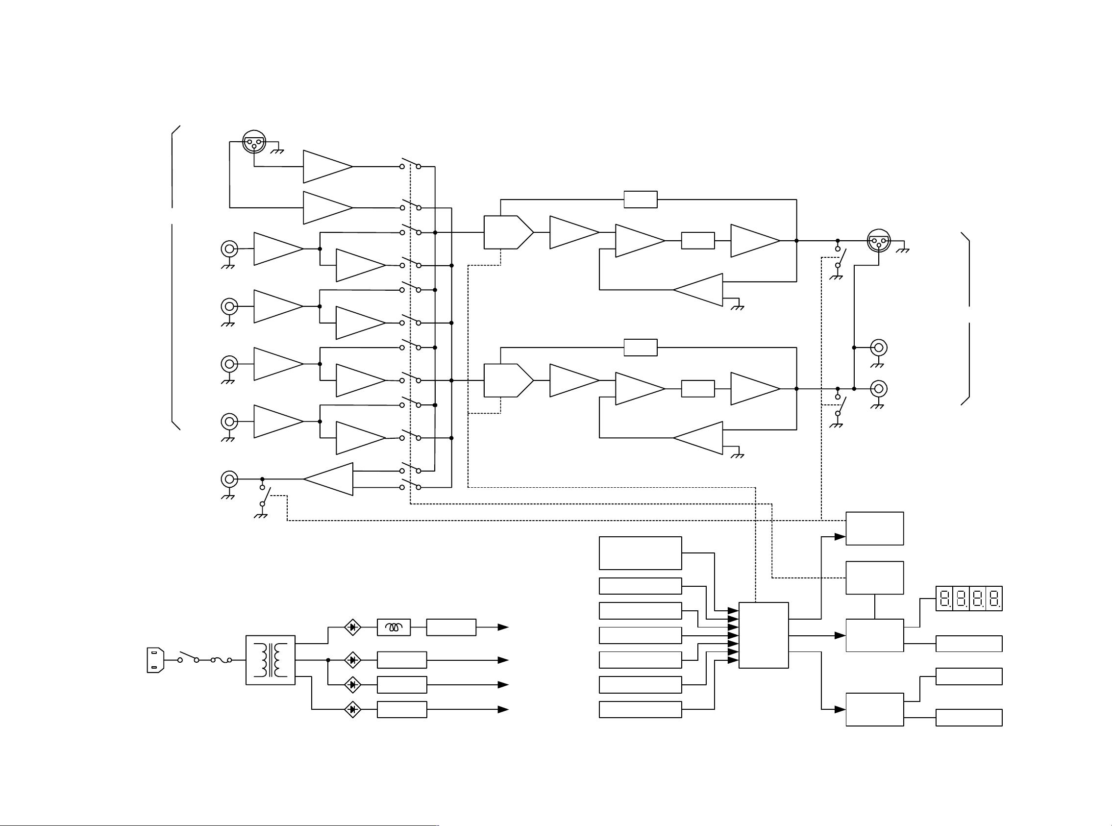
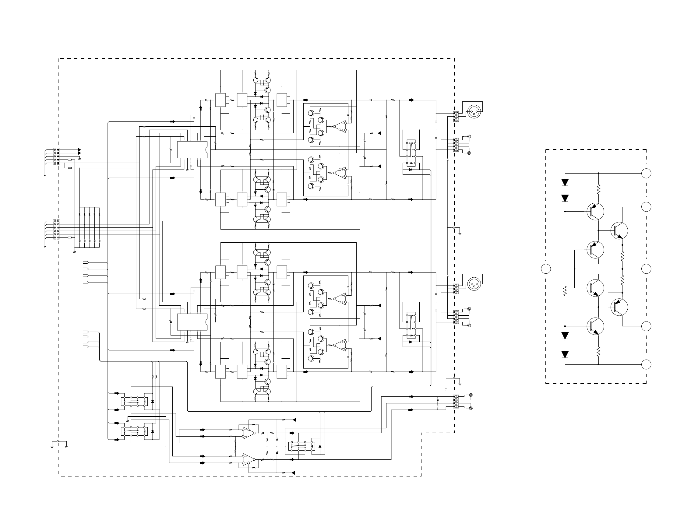
2. BLOCK DIAGRAM
BALANCED
Ach INPUT
SACD/CD
LINE-1
LINE-2
TAPE
12
3
+
-
+
-
+
-
+
-
+
-
VOL
VOL
NFB
NFB
I/V
I/V
12
BALANCED
3
Ach PRE OUT
UNBALANCED-1
UNBALANCED-2
REC OUT
+
-
±12V
+5V
+5V
±22V
AMP
RELAY
VOL.
µP
INPUT
SELECTOR
VOLUME
ATT SW.
DISPLAY SW.
IR
ID SW.
MODE SW.
µP
MUTE
DRIVER
RELAY
DRIVER
DISPLAY
DRIVER
BUS
CONTROL
LED DISPLAY
IN
OUT
3 4
Page 6
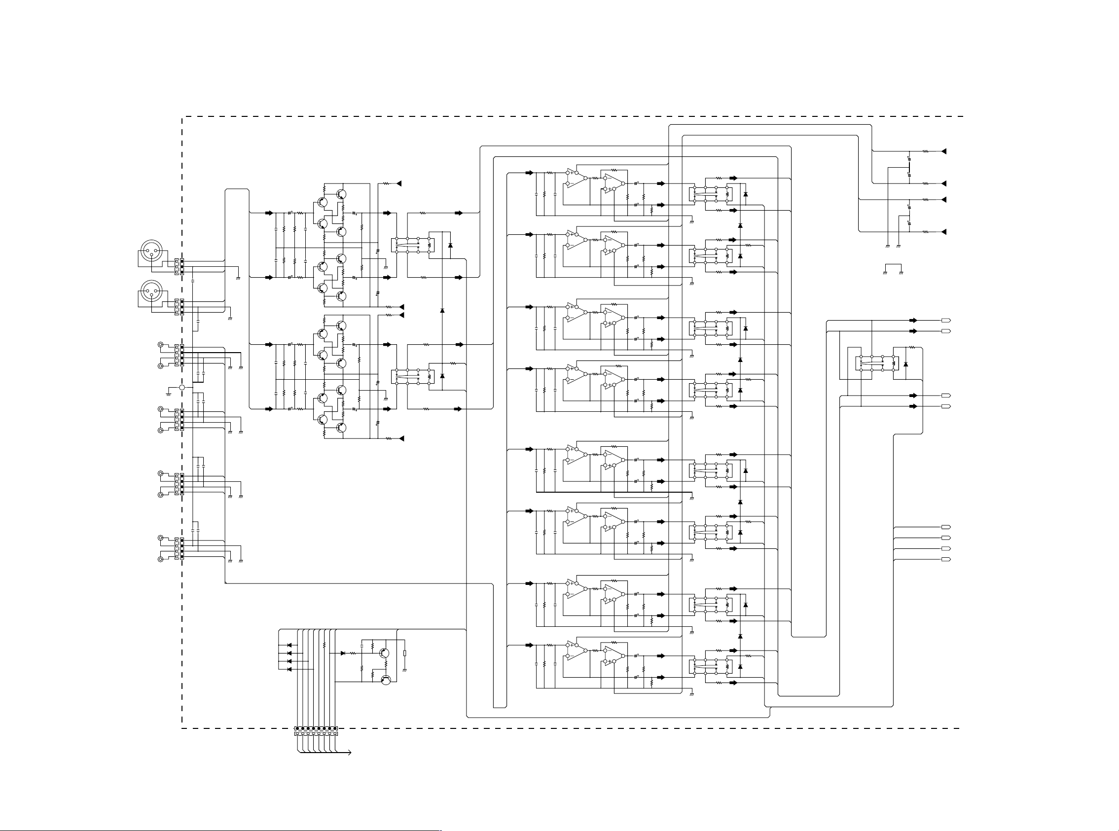
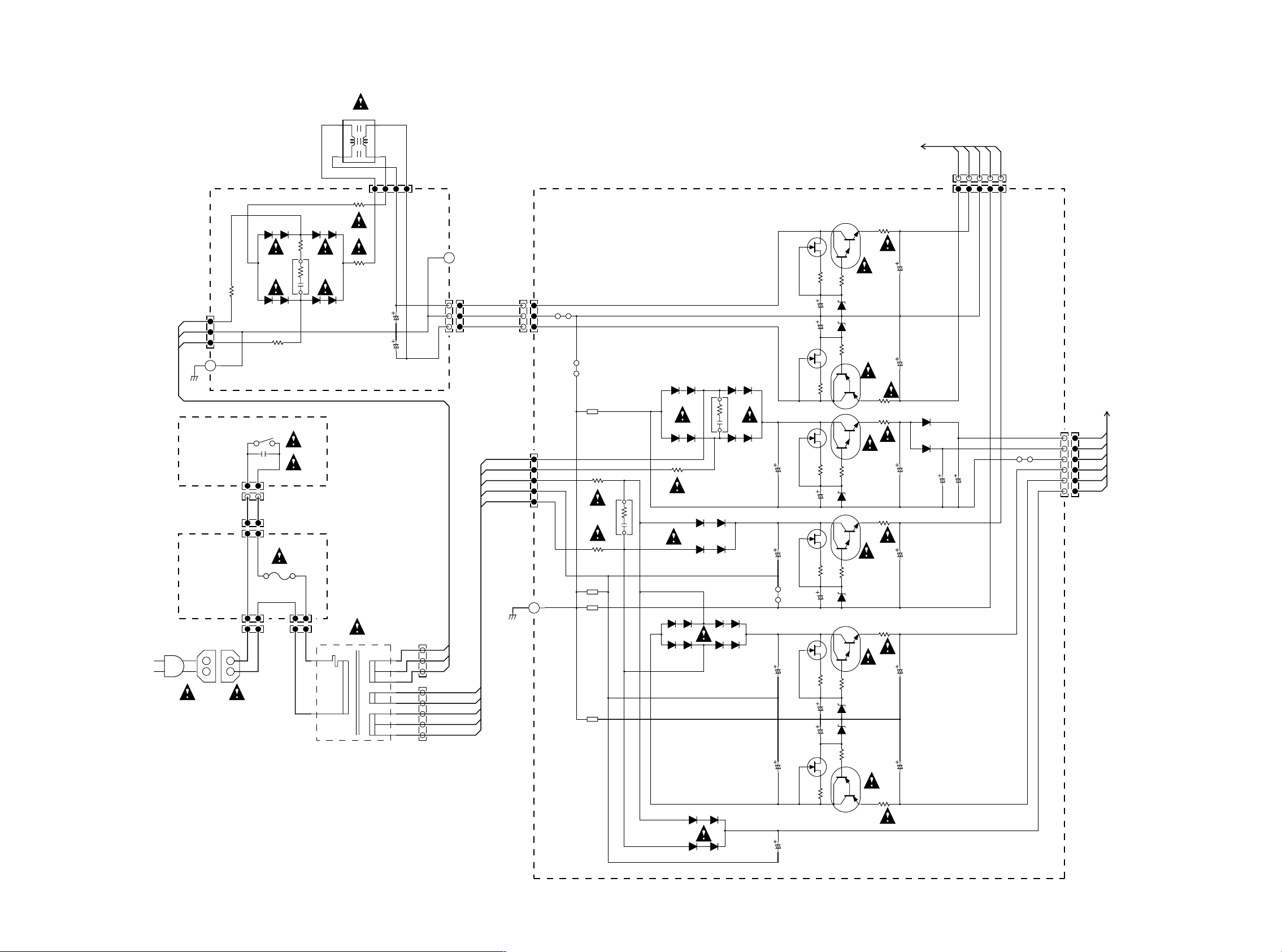
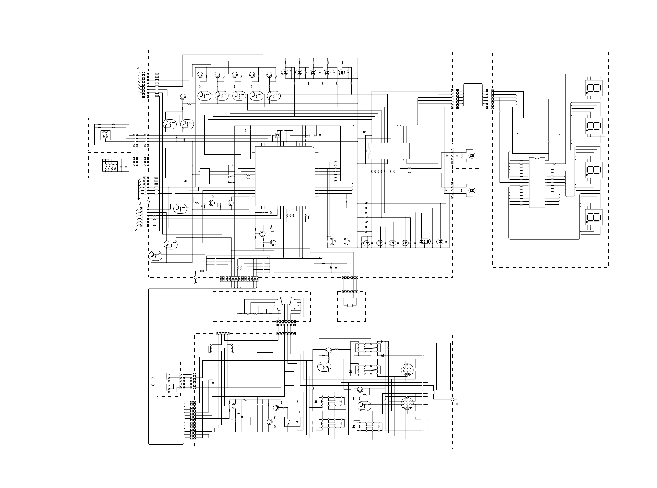
3. SCHEMATIC DIAGRAM
BALANCED
B
A
2
CD
LINE_1
LINE_2
TAPE
P101 1/2
1
-TAPE
BAL
MUTE
-12
RC36
+22V
22
CC36CC38
1000/25V1000/25V1000/25V
RC38
-22V
22
RC35
+22V
22
CC35
1000/25V
CC37
RC37
-22V
22
A_GNDB_GND
B_-
B_+
RC21
BI
22
DC21
-12
A_-
A_+
-TAPE
BAL
MUTE
-12
B_+22
22/25V
2.26K
22/25V
22/25V
22/25V
22/25V
22/25V
22/25V
22/25V
22/25V
22/25V
22/25V
22/25V
22/25V
22/25V
22/25V
2.26K 2.26K 2.26K 2.26K 2.26K 2.26K
22/25V
B_+22
LC04
B_GND
LC03
A_GND
LC06
B_GND
LC05
A_GND
LC08
B_GND
LC07LC09
A_GND
LC10
B_GND
A_GND
8
8
8
8
8
8
8
8
R448
(JUMPER)
435
910
R446
(JUMPER)
R447
(JUMPER)
435
910
R445
(JUMPER)
R464
(JUMPER)
435
910
R462
(JUMPER)
R463
(JUMPER)
435
910
R461
(JUMPER)
R480
(JUMPER)
435
910
R478
(JUMPER)
R479
(JUMPER)
435
910
R477
(JUMPER)
R496
(JUMPER)
435
910
R494
(JUMPER)
(JUMPER)
435
910
R493
(JUMPER)
1
+
-
DC04
1SS176
12
1
RC03
+
22
-
DC03
1SS176
12
1
+
-
DC06
1SS176
12
RC05
1
22
+
-
DC05
1SS176
12
1
+
-
DC08
1SS1761SS176
12
RC07
1
22
+
DC07
-
1SS176
12
1
+
-
DC10
12
DC20 DC19 DC18 DC17
11EQS10 11EQS10 11EQS10 11EQS10
RC09
1
22
+
-
DC09
1SS176
12
C420
R444
100K
C418
R442
100K
B_-22
A_+22
C419
100K
R443
C417
R441
100K
A_-22
B_+22
C428
R460
C426
R458
100K
B_-22
A_+22
C427
R459
100K 100K
C425
R457
100K
A_-22
B_+22
C436
R476
100K
C434
R474
100K100K
B_-22
A_+22
C435
R475
100K
C433
100K
R473
A_-22
B_+22
C444
R492
100K
C442
100K
R490
B_-22
A_+22
C443
R491
100K
C441
R489
A_-22
B_-
-12ST
B_+
A_-
CD
-12
A_+
B_-
-12ST
B_+
A_-
L_1
-12
A_+
B_-
-12ST
B_+
A_-
L_2
-12
A_+
B_-
-12ST
B_+
A_-
TAPE
-12
A_+
B_-
B_+
A_-
A_+
LC21
A_+22
A_-22
8
B_-22
B_GND A_GND
435
+
-
91012
RC34
22
Q412
1
2SC2240
R412
15.4k
2
Q404
3
2SA970
2
3
1
1
3
R416
15.4K
R414
15.4K
3
1
1
3
R410
15.4K
R411
15.4K
3
1
1
3
R415
15.4K
R413
15.4K
3
1
1
3
R409
15.4K
BI
TAPE
MUTE
22
RC18
11.6(TAPE)
ON :-11.7 / OFF:+11.6
S.T.:-11.7 / BI.:+11.5
TAPE
MUTEBI-12
22.622.6
C412
R420R424
22/25V
3
R428
1SS176
JC03
W018
100K
Q416
2SA970
1
1
Q414
2SA970
3
R426
100K
C410
22/25V
22.6 22.6
R418 R422
3
Q410
2SC2240
1
1
Q411
2SC2240
3
22.6
C411
R419
22/25V
22.6
R423
3
R427
100K
Q415
2SA970
1
1
Q413
2SA970
3
R425
100K
22.6
R421
C409
22/25V
22.6
R417
3
Q409
2SC2240
1
0.1
CC11
DC15
RC13
RC11
15K
22K
RC12
RC15
2
2
2
2
2
2
2
-12
-11.7
8
8
C404
C402
C403
C401
-TAPE
TAPE:-11.6
OTHER:+11.0
C464
10/35V
R404
226K
(N.C)
R402
226K
(N.C)
C462
10/35V
C463
10/35V
(N.C)
R403
226K
R401
226K
(N.C)
C461
10/35V
DC11
DC12
DC13
DC14
R408
226
220P
C408
R500R498R499R497
22.6K22.6K22.6K22.6K
220P
C406
R406
226
R407
226
220P
C407
220P
C405
R405
226
CD
L_1
BAL
1D3
1D3
1D3
1D3
11.6(BALANCED)
11.6(SACD/CD)
11.6(LINE1)
BALCDL_1
1234567
1234567
2
Q408
2SC2240
Q406
2SC2240
2
2
Q402
2SA970
Q403
2SA970
2
2
Q407
2SC2240
Q405
2SC2240
2
2
Q401
2SA970
L_2
11.6(LINE2)
L_2
BAL_BIN_-
J004
1
2
3
J003
1
3
J006
B
A
J008
B
A
J010
B
A
J012
B
A
J402
W008
1
2
3
W007
1
2
3
1
1
2
2
3
2
4
1
J005
EARTH
W010
1
1
2
2
3
2
4
1
J007
W011
1
1
2
2
3
2
4
1
J009
W012
1
1
2
2
3
2
4
1
J011
BAL_BIN_-
1
2
BAL_BIN_+
3
0.1
C452
J401
BAL_AIN_-
1
2
BAL_AIN_+
3
0.1
C451
J403W009
CD_B_IN
1
2
3
CD_A_IN
4
0.1
0.10.1
C453
C454
1
2
0.1
J405
C456
C455
LINE1_B_IN
1
2
3
LINE1_A_IN
4
0.1
0.1
J407
C458
C457
LINE2_B_IN
1
2
3
LINE2_A_IN
4
0.1
0.1
J409
C459
C460
TAPE_B_IN
1
2
3
TAPE_A_IN
4
A_GND
A_GND
A_GND
A_GND
A_GND
B_GND
BAL_BIN_+
BAL_AIN_-
B_GND
BAL_AIN_+
B_GND
B_GND
B_GND
-22V
R432
(JUMPER)
1
435
91012
R430
(JUMPER)
+22V
-22V
(JUMPER)
435
91012
(JUMPER)
+22V
LC11
GND
+
-
DC16
R431
1
+
DC01
-
R429
LC02
CC34
220/25V
8
B_GND
CC32
220/25V
RC32
22
RC33
22
LC01
CC33
8
A_GND
CC31
220/25V 220/25V
RC31
22
-12ST
10K
3
2
QC11
2SA1048
1
4.7K
RC14
22K
123
S.T.:-11.7
BI.:+11.5
QC12
2SC2458
DC02
11EQS10
RC01
1SS176
B_-
1SS176
-12ST
B_+
22
BAL
-12
CD_B_IN
CD_A_IN
LINE1_B_IN
A_-
LINE1_A_IN
A_+
LINE2_B_IN
LINE2_A_IN
TAPE_B_IN
TAPE_A_IN
R436
R434
C414
(N.C)
R435
C413
R433
(N.C)
R452
C422
R450
(N.C)
R451
C421
R449
(N.C)
R468
C430
(N.C)
R467
226
C429
R465R481 R466
(N.C)
R484
C438
R482
(N.C)
R483
226
C437
(N.C)
8
5
226
OPA2604AP
6
Q418
2/2
220p
22.6K
C416
8
5
226
OPA2604AP
6
Q417
2/2
220p
22.6K
C415
8
5
226
OPA2604AP
6
Q420
2/2
C424
220p
22.6K
8
5
226
OPA2604AP
6
Q419
22.6K
226
22.6K22.6K 22.6K
226
22.6K
2/2
C423
220p
8
5
OPA2604AP
6
Q422
2/2
220p
C432
8
5
OPA2604AP
6
Q421
2/2
C431
220p
8
5
OPA2604AP
6
Q424
2/2
220p
C440
8
5
OPA2604AP
6
Q423
2/2
220p
C439
R440
2.26K
2
R438
7
2.26K
R437
7
2.26K
R454
7
2.26K
R453
7
2.26K
R470
7
2.26K
R469
7
2.26K
R486
7
2.26K
R485 R495
7
2.26K
OPA2604AP
3
Q418
1/2
2
OPA2604AP
3
Q417
1/2
2
OPA2604AP
3
Q420
1/2
2
OPA2604AP
3
Q419
1/2
2
OPA2604AP
3
Q422
1/2
2
OPA2604AP
3
Q421
1/2
2
OPA2604AP
3
Q424
1/2
2
OPA2604AP
3
Q423
1/2
1
4
RC74
R439
2.26K
1
4
RC73
2.26K
R456
2.26K
1
4
R455
2.26K
1
4
R472
2.26K
1
4
R471
2.26K
1
4
R488
2.26K
1
4
R487
2.26K
1
4
RC79 RC80 RC77 RC78 RC75 RC76
FROM J201
5 6
Page 7
1
2
3
1
2
3
1
2
3
1
2
3
1
2
3
1
2
3
3
4
2
1
5
6
QH05
QH06
DH01
RH03
RH04
QH03
QH01
QH02
QH04
RH01
RH02
DH03
DH04
DH02
JH02
JH02
RH05
JH02
JH02
JH02
JH02
22
22
470
470
-
+
68K
+B
+OUT
-OUT
-B
2SC2240
2SA970
1SS176
2SA970
2SA970
2SC2240
2SC2240
1SS176
1SS176
1SS176
HDAM-SA
12345
W005
FROM J805
1
2
W019
3
4
5
6
W018
FROM J205
EARTH
J501
12345
1
2
CCLK
3
DATA
4
MUTEB
5
DGND
6
J502
P101 2/2
-22V
+22V
A_G
L504
D_G
+5V
L503
CSB-A
CSB-B
L505
(N.C)
GND
GND
-22V
+22V
GND
4.7K
R551
1000P
C554
B_-
B_+
A_-
A_+
-TAPE
BAL
MUTE
-12
4.7K
4.7K
4.7K
R548
R549
R550
1000P
1000P
1000P
C552
C551
C553
-TAPE
BAL
MUTE
-12
4.7K
R547
0.01
C533
B_+
B_-
B_-
B_+
A_-
A_+
A_+
A_-
A_+
B_+
A_-
B_-
LC51LC52
8
8
435
91012
GND
435
91012
R544
(JUMPER)
R542
R543
(JUMPER)
R541
Q512
681
332
R520
R512
2SA1349
5
3
2
6
7
1
3
Q520
2SA970
2
Q504
C550
22/25V
43
HDAM-SA
6
100K
R536
C524
(N.C)
C546
47
47
-12
BAL
-TAPE
22
22
RC16
RC17
1
+
DC51DC52
-
1SS176
1
+
-
1SS176
C526
Q530
220/25V
WM8816
C525
Q529
220/25V
WM8816
87654321
LIN
LFO
CSB
LGND
DVDD
RFO
RIN
RGND
DGND
CCLK
DATA MUTEB
C522
(N.C)
GND
C523
(N.C)
87654321
LIN
LFO
CSB
LGND
DVDD
RFO
RIN
RGND
DGND
CCLK
DATA MUTEB
C521
(N.C)
GND
22/25V
C528
LMO
220/25v
AVDD
RMO
161514131211109
LMO
RMO
161514131211109
C544
22/25V
2
Q502 Q526
100K
R534
C548
22/25V
43
HDAM-SA HDAM-SA
6
2
Q503
C549
22/25V
43
6
100K
R535
C545
22/25V
C527
220/25v
AVDD AGND
AGND
C543
22/25V
Q501 Q505
2
100K
R533
C547
22/25V
43
HDAM-SA HDAM-SA
6
B_-
B_+
A_+
A_-
Q508
2
1
R508
100
34
HDAM-SA HDAM-SA
5
6
R504
1.21K
R502
1.21K
2
Q506
1
R506
100
34
HDAM-SA
5
6
Q507
2
1
R507
100
34
HDAM-SAHDAM-SA
5
6
R503
1.21K
R501
1.21K
2
1
R505
100
34
5
6
RC56
10k
6
OPA2604
RC52
10k
5
10k
RC54
10k
RC53
RC51
10k
3
OPA2604
RC55
10k
2
2
D512
D504
HSS81
1
HSS81
5
D516
HSS81
D508
HSS81
2
Q524
2SC2240
1
7
6
5
Q516
2SC3381
R516
R592
46.4
C542
22/25V
C540
R590
22/25V
46.4
Q510
681
R510
2SA1349
3
2
1
7
Q518
2SA970
2
D510
D502
HSS81
1
HSS81
5
D514
HSS81
D506
HSS81
2
Q522
2SC2240
3
Q514
2SA1349
681 681
R514
Q511
2SA1349
5
67
1
Q519
2SA970
2
D511
D503
HSS81
1
HSS81
5
D515
HSS81
D507
HSS81
2
Q523
2SC2240
5
Q515
2SC3381
R515
R591
46.4
C541
22/25V
C539
22/25V
R589
46.4
Q509
681 681
R509 R511
2SA1349
3
21
7
Q517
2SA970
2
D509
D501
HSS81
1
HSS81
D513
5
HSS81
D505
HSS81
2
Q521
2SC2240
3
Q513
2SC3381
681 681
R513
RC58
10k
8
CC51
7
22/25v
RC60
2/2
QC51
100K
RC59
100K
1/2
QC51
CC52
1
22/25v
4
RC57
10k
Q528
2
1
1
4
3
5
1
6
100p
C508
3
2
100100
R596R594
3
332
R524
332
R518
5
6
3
100p
C506
2
1
1
4
3
5
1
6
3
67521
332
R522
3
2
3
2
Q527
1
1
4
3
HDAM-SA
5
1
6
100p
C507
3
21367
R523 R519
332
R517
5
100 100
R593 R595
6
3
100p
C505
2
Q525
1
1
4
3
HDAM-SA
5
1
6
3
67521
332 332 332
R521
RC63
22
RC62
226
CC55
220/25v
LC53
8
CC56
220/25v
RC61
226
RC64
22
R584
22.6
R588
22.6
R582
22.6
R586
22.6
R583
22.6
R587
22.6
R581
22.6
R585
22.6
+22V
435
91012
-22V
Q544
R576
2SC2240
1
15.4K
2
Q536
3
2SA970
3
2
1
1
2
Q540
3
2SC2240
3
2
R580
Q548
15.4K
1
2SA970
Q542
R574
2SC2240
1
15.4K
2
Q534
3
2SA970
3
2
1
1
2
Q538
3
2SC2240
3
2
R578
Q546
15.4K
1
2SA970
Q543
2SC2240
R575
1
15.4K
2
Q535
3
2SA970
3
2
1
1
2
Q539
3
2SC2240
3
2
R579
Q547
15.4K
1
2SA970
Q541
2SC2240
R573
1
15.4K
2
Q533
3
2SA970
3
2
1
1
2
Q537
3
2SC2240
3
2
R577
Q545
15.4K
1
2SA970
-12
MUTE
1
+
DC53
-
1SS176
C538
0.1
Q532
2
1/2
R572
1
100
OPA2604
4
3
5
8
R570
100
OPA2604
7
6
Q532
2/2
C536
0.1
C537
0.1
Q531
2
1/2
R571
1
100
OPA2604
4
3
5
8
R569
100
OPA2604
7
Q531
6
2/2
C535
0.1
22/25V
C512
3.3M
R564
3.3M
R568
R538
(JUMPER)
C514
470/25v
C516
470/25V
R540
(JUMPER)
3.3M
R566
3.3M
R562
22/25V
C510
22/25V
C511
3.3M
R567
R537
(JUMPER)
C513
470/25v
C515
470/25V
R539
(JUMPER)
3.3M 3.3M
R565 R563
3.3M
R561
22/25V
C509
R532
226
R528
100k
+22V
-22V
R526
100k
R527
100k
+22V
-22V
R525
100k
L502
8
43 5
91012
+
-
1
MUTE
D518
1SS176
R530
226
R531
226
L501
8
91012
-
D517
R529
226
-12
435
+
1
MUTE
-12
J506
C520
(N.C.)
J508
(N.C.)
C518
C530
C529
C519
(N.C.)
J505
C517
(N.C.)
J507
CC57
0.1
CC54CC53
(N.C.) (N.C.)
JC51 W013
J016
W015
3
2
1
W017
4
3
2
1
0.1
EARTH
0.1
3
2
1
W014
4
3
2
1
W016
EARTH
4
3
2
1
21
BALANCED
3
3
2
1
J018
1
2
4
3
2
2
1
1
J020
J015
3
2
1
J017
1
2
4
3
2
2
1
1
J019
J014
1
4
2
3
2
2
1
1
J013
PREOUT 1
PREOUT 2
21
3
PREOUT 1
PREOUT 2
B
REC OUT
A
OUT
BALANCED
OUT
B
A
7 8
Page 8
L002
1
3
TO J501
2
4
W005
54321
AC
W001
GND
PS91
PF01
J801
36V
1
0V
2
36V
3
J001
12
D801
21DQ10
-32.8 +32.8
R801
(JUMPER)
D805
21DQ10
(JUMPER)
P851
POWER SW
S891
12
C891
0.01
21
J891
21
W003
21
J872
12
J874
2A, 125V [/F/U]
T500mA, 250V [/N]
J871
21
12
W002
12
1
FUSE
21DQ10
R802
F871
G801
D806
R826
2
J875
12
D803
21DQ10
1
D807
21DQ10
J873
21
1/6w
0.47 6.8
1
2
D804D802
21DQ1021DQ10
D808
21DQ10
R828
1 1/4w
R827
1 1/4w
L001
12 3 4
C801C802
10000/50V10000/50V
10
9
8
7
6
5
4
3
J802
+30V
0V
-30V
1
2
3
5
4
3
2
1
W801
36V
0V
36V
12V
0V
15V
0V
15V
1
2
3
J803
54321
J805
+5V
A_G
D_G
C820
1000/10v
+5.0
+5.0
-22V
+22V
C819
1000/10v
U812
(N.C)
+5VD
+5VM
M_G
+12V
-12V
ON
J807
TO J204
W006
1
1
2
2
3
3
4
4
5
5
6
6
Q801
1
G
+25.4
1
G
-24.9
R806
100
1
G
+7.9
1
G
1
G
+13.5
1
G
-19.6
-19.9
+32.0
R805
R824
+6.5
R819
+19.6
R811
R812
D
S
100
D
S
-32.0
+13.2
D
S
100
+20.2
D
S
100
D
S
100
D
S
100
2
3
2
3
2
3
2
3
2
3
2
3
2SD1415
2
2SD1415
2
R835 R834 R831R832R833
2SB1020
3
-24.0
2SB1020
3
3
3
Q805
3
100 100 100100100
3
Q806
+24.0
D809
HZ24-1L
HZ24-1L
Q802
+7.5
D839
7.5V
+6.2
D829
6.2V
+13.0
D819
13V
D820
13V
-13.0
R836
12
+23.0
D810
12
-23.0
12
+6.3
Q811
2SD1415
+5.1
1
Q809
2SD1415
1
+11.9
100
12
-11.9
R808
2.2
R807
2.2
R825
3.3
R820
3.3
R813
3.3
R814
3.3
C805
C806
C818
470/25v
470/25v
470/25V
C815C812
100/25V2200/25v
C811
220/25v
D840
1D3
D841
1D3
P801
Q803
2SK246
GND
J804
1
1
U811
+30V
2
2
0V
3
3
J806
5
4
3
2
1
-30V
12V
15V
15V
(N.C)
U801
(N.C)
L804
0V
0V
R815
1 1/4W
G803
0.47 6.8
R816
1 1/4W
L806
L803
(N.C)
L805
D832
D831
21DQ10 21DQ10
D836
D835
21DQ10 21DQ10
R822
1 1/4w
D823
11EQS10
D821
11EQS10
D811
D812
11EQS10
11EQS10
D815
D816
11EQS10
11EQS10
G802
11EQS10
11EQS10
D813
11EQS10
11EQS10
D828D827
11EQS1011EQS10
21DQ10
21DQ10
D824
D822
D817
D833
D837
21DQ10
0.47 6.8
D838
21DQ10
D814
11EQS10
D818
11EQS10
D834
C816
C813
C807
C808
6800/16v
470/25v
U803
470/25V
470/25V
+20.0
470/25v
Q804
2SK246
2SK246
2SK246
(N.C)
2SK246
220/25v
220/25v
2SK246
C803
470/25v
C804
Q812
C817
470/25V
Q810
C814
100/25V
Q807
C809
C810
Q808
W004
1
2
3
C821
D825 D826
11EQS10
11EQS10
1/50v
9 10
Page 9
S251
P251
P261
R251
10k
R253
10k
BA
12
3
C
INPUT SELECTOR
35
21468
S261
R252
10k
R254
10k
VOLUME
7
PU01
10k
TO JC03
J201
L301
1
1
BAL
L302
2
2
CD
L303
3
3
L-1
L304
4
4
L-2
L305
5
5
TAPE
L306
6
6
MUTE
L307
7
7
W018
BI
L308
8
8
-B
J202
W022
J251
1
2
3
4
J262
1
2
3
0.01
0.01
C262
C261
TO J502
FROM J807
1
1
1
2
2
2
3
3
3
4
4
4
W021
J203
1
1
1
2
2
2
3
3
3
J204
L220
1
+5VD
1
L201
2
+5VM
2
L202
3
M_G
3
W019
L203
4
+12V
4
L204
5
-12V
5
L205
6
ON
6
J207
J205
1
1
CSA
2
2
CSB
3
3
R355
100
CLK
W006
4
4
R356
100
DATA
5
5
MUTE
6
R358
6
G
(JUMPER)
Q224
DTC114ES
1
2
3
1
3
1
3
Q206
DTC114ES
Q223
DTC114ES
2
DTC114ES
1
3
123
C251
0.01
Q222
2
Q208
2SA1048
CBE
R221
Q209
2SA1048 2SA1048 2SA1048
1231
CBEC
R223
R222
22k
4.7K
Q207
DTC114ES
1
2
3
C252
0.01
C213
470/10v
R208
100k
2
2SA1048 2SA1048
1231
CBEC
22k
R224
4.7K
R225
Q210
DTC114ES DTC114ES DTC114ES
1
2
3
8
1
VCC
A0
7
2
WP
A1
6
3
SDL
A2
5
4
SDA
GND
Q202
AT24C04
R245
Q221
1
C
2SC2458
2
B
3
0.1
10k
E
R207
C207
C265
C266
C267
C268
C269
L261
Q213
Q211 Q215
22k
R226
B
2
4.7K
4.7K
R227
Q212 Q216
DTC114ES DTC114ES
1
3
22k
0.01
0.01
0.01
0.01
0.01
121110987654321
W020
Q214 Q218
1
2
3
C208
0.1
R204 R233
4.7k
R205
4.7k
R206
22k
Q205
C
1
2SC2458
2
B
4.7k
E
3
R246
RXD
100
G
R261
5V
BI
-12V
+12V
31
3
EC
E
22k
22k
R230
R228
2
B
4.7K
R229
1
2
2
3
10k
10k
R202
R203
17
18
19
SEL.A
20
SEL.B
21
MUTE1
22
MUTE2
23
MUTEB
22k
24
25
R234
22k
26
SDA
27
SCL
28
VOL_CSA
29
VOL_CSB
30
POWER_OFF
31
0.1
C206
33
R210
10k
Q219
2SA1048
3
10k
R241
2
1
10k
R243
R242
10k
R244
10k
M
ID
ST
C264
0.01
ICE4
TXD
100
R262
C263
0.01
C262
0.01
C261
0.01
J206
123456789101112
PS01
ID:2
R275
22
C271
10/25v
ID:4
ID:3
R288 R290
R289R287R286
4.7k 10k4.7k4.7k4.7k
ID 1 :5V
ID 2 TO 6 :0V
0.1
C272
C276
0.1
Q278
STEREOBI-AMP
PS71
S273
-2
S273
-1
ID:1
TXD
RXD5VG
J274
4321
WRITE WRITE
-1
213
S271
OPERATE
J278
W025
1
1
1
1
2
3
2
3
4
4
5
5
6
1
2
2
2
3
3
3
4
4
5
5
1
2
W020
3
4
5
6
7
8
9
10
11
12
0.1
C274
4
5
J277
J271
1
M
2
ICE4
3
4
ST
5
ID
6
TXD
7
RXD
8
5V
9
G
10
+12V
11
-12V
12
BI
R272 R273
4.7k 4.7k
546
OPARATE
2
(N.C)
C277
-2
S271
3
Q272
2SA1048
1
R271
100
4.7K
R274
R332
Q217
R231
ID:5
R295
1
2SC2458
3
3
E
B
2
4.7K
1
3
VOLB
VOLA
ICE4
R240
R211
2
ICE4
ID SW
9
10
10k
Q279
2SA1048
R293
10k
R294
10k
C309
D310
10/25V
22k
R232
BALANCE CD LINE1 LINE2 TAPE
560
R331
2
C204
X201
30p
8M
C205
30p
RES
GND
TEST
OSC2
OSC1
Q201
HD64F3664F
ICE1
MASTER_H
VOL_DAT
VOL_CLK
10k
10k
R214
R213
Q220
2SC2458
M
-1
-2
7
S274
S274
13
15
12
G
ID
RT
5V
123 4 56
123456
5VGIDRTSL
12345
ID1 :5.1V
ID2 :4.3V
ID3 :3.4V
ID4 :2.6V
ID5 :1.8V
ID6 :0V
2.2K
R292
2
R276
2.2K
41
5.1
32
Q273
PC817
VC1
ICE3
ICE2
10k
R215
1
ID:1
6
SL
MA
MA
6
J275
R277
VCC
RC5
22k
22k
1
3
8
11
ID:6
3
1
2
10k
10k
R336
R334
C310
C311
10/25V
10/25V
D312
D311
560
560
R335
R333
22k
Q203
S-806
R201
2
3
C-X
C201
1
0.1
0.1
C203
C202
1
2345678910111213141516
X2
X1
AVCC
64
63
62
IDSW
61
ATT
60
STEREO
59
DISPLAY
58
57
56
55
54
DISP_STB
53
DISP_DAT
52
DISP_CLK
51
DISP_CLR
50
4932
TXD
RXD
CLEAR
48
4746454443424140393837363534
10k
22k
R217
R216
ST
RXD
TXD
2
3
4
5
J276
W024
560
C279
(N.C)
0.0
0.00.0
ID
R212
22
11.5 11.2
R284
22k
2
Q275
DTC114ES
22
R278
11.3
1
D275
1
C278
(N.C)
10k
R338
D313
0.1
0.1
C211
C210
Q274
2SA1048
L271
+
-
L272
+
-
C312
10/25V
D314
560
R337
R218
22k
R219
22k
R220
22k
R235
22k
R236
22k
R237
22k
R238
22k
1
S201
2
DISPLAY
0.1
22/25v
C209
123
R285
22
4.7K
R283
1
3
435
91012
435
91012
10k
R340
0.1
C212
2
ATT
12345
12345
J211
IR SENSOR
PU71
-11.6
8
8
C313
10/25V
560
R339
CLK
STB
CLR
C341
470/10v
24 23 22 21 20 19 18 17 16 15 14 13
P6P5P4P3P2
VDD
0.1
C301
STB
DATA
CLK
CLR
C357
22k
R239
C356
C355
C354
C353
C352
C351
D305
S202
10k
R301
J211
2
IR
13
Q204
L273
1
+
-
L274
1
+
-
D273
123
Q276
2SA1048
22
R281
22k
4.7K
R280
1
R279
3
Q277
DTC114ES
0.0
11.3
1
+
D274
-
-11.4
L275
P10P9P8
P7
560
470
470
470
R303
R302
R304
R305
10/25V
10/25V
10/25V
10/25V
10/25V
10/25V
10/25V
D306
0.1
C303
POWER ATT B A SYNC
D271
435
8
91012
D272
11EQS1D
435
8
91012
11.2
4.1
2
435
8
91012
P11
100
R306
11EQS1D
R282
STB
CLR
CLK
DATA
P1
VSS
STB
CLR
CLK
DATASO
Q301
NJU3716L
P16
P15
P14
P13
P12
VSS
121110987654321
R343
220
100
R307
D307
0.1
C304
R344
330
220
R353
RED
GRN
D308
0.1
C305
131
0.1
0.1
2
D309
C306
C307
P271
0.1
C273
22k
8467
513
2
8467
513
2
C280
0.1
C281
0.1
9
C291
0.1
REMOTE
IN
J272
C282
0.1
C283
1000P
C284
0.1
C292
0.1
9
REMOTE
OUT
C285
1000P
J273
C286
0.1
C287
1000P
C288
0.1
C289
0.1
C290
0.1
0.1
C308
D317
DISPLAY
IN(J272)
1:IN-H
2:IN-C
3:RETURN-H
4:RETURN-C
5:MASTER-G
6:MASTER-G
7:+12V
8:-12V
OUT(J273)
1:OUT-H
2:OUT-C
3:RETURN-H
4:RETURN-C
5:DETECT
6:MASTER-G
7:+12V
8:-12V
L276
J301
6
5
4
3
2
1
J303
5
4
3
2
1
C359
10/25V
J302
5
4
3
2
1
C358
10/25V
C316
0.1
6
5
4
3
2
1
C314
PU51
C315
PU61
W271
W023
0.1
10k
R341
D315D316
10k
0.1
R342
1
2
3
4
5
6
DISPLAY LIGHTDISPLAY LIGHT
P301
J304
1
2
3
4
5
6
12345
CLR
STB
CLK
DATA
0.01
0.01
C340
C339
0.1
C302
R323
560
1
2A
R318
560
2
2F
R317
560
3
2G
R319
560
4
2E
R320
560
5
2D
R321
560
6
2C
R322
560
7
2B
8
R327
560
9
4A
R310
560
10
4F
R309
560
11
4G
R311
560
12
4E
R324
560
13
4D
R325
560
14
4C
R326
560
15 16
4B
P11
P12
P13
P14
P15
P16
P17
VSS
P18
P19
P20
P21
P22
P23
P24 DATA
Q302
NJU3719L
30
VDD
R308
560
29
P10
28
P9
R316
560
27
P8
P7
P6
P5
P4
P3
P2
P1
CLR
STB
CLK
3A
R329
560
26
3F
R328
560
25
3G
R330
560
24
3E
R313
560
23
3D
R312
560
22
DP
R314
560
21
3C
R315
560
20
3B
19
CLR
18
STB
17
CLK
DATA
D301
678910
2A
2F
2G
2E
2D
D302
2C
2B
3A
3F
3G
3E
3D
D303
DP
3C
3B
4A
4F
4G
4E
4D
D304
4C
4B
678910
678910
6789
12345
12345
12345
10
11 12
Page 10
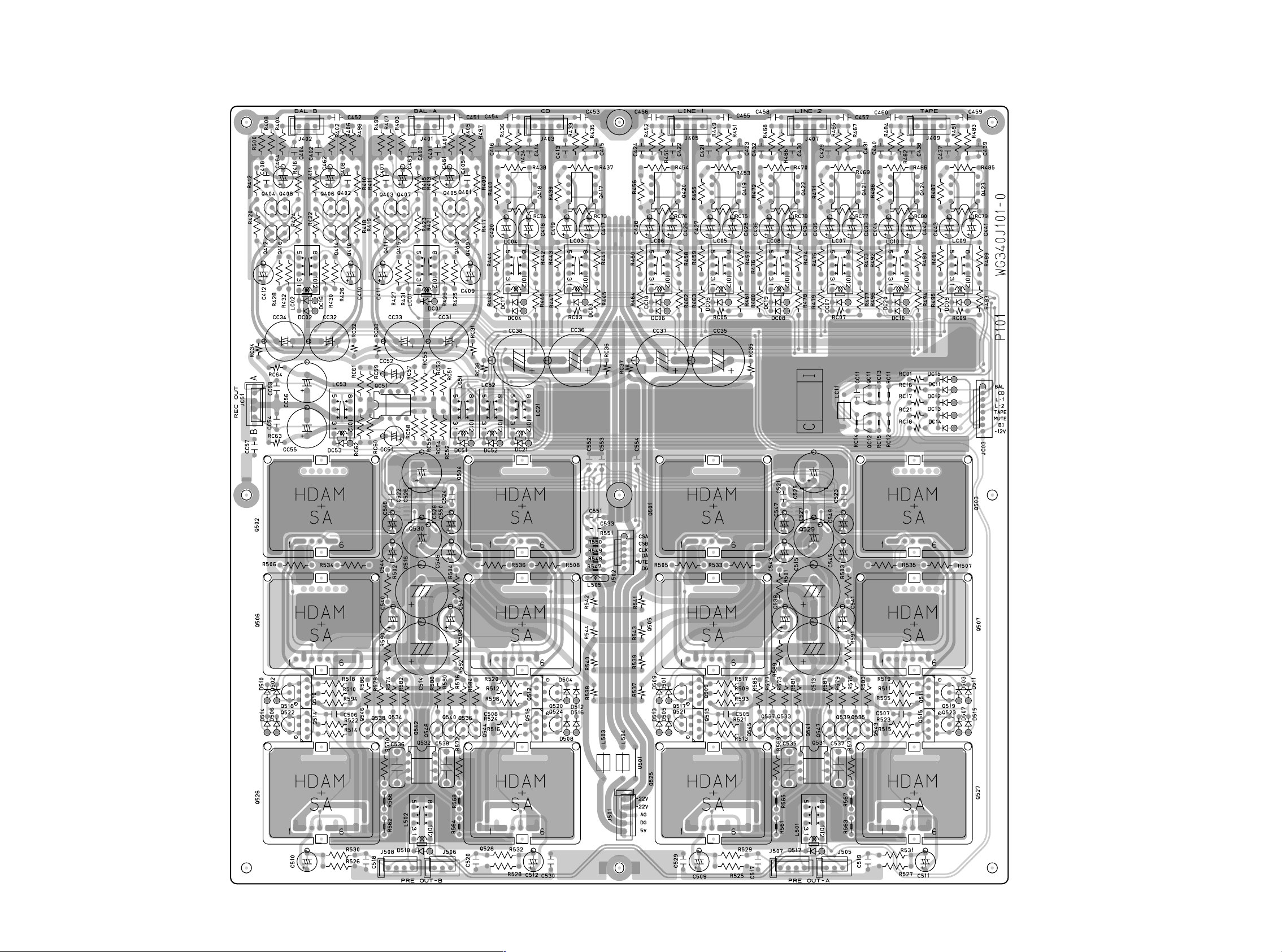
4. PARTS LOCATION
P101
Q408
Q404
Q416
Q412
Q402
Q406
Q410
Q414
DC16
DC02
DC53
Q407
Q403
Q415
Q411
QC51
Q401
Q405
Q409
Q413
DC01
DC51
Q530
DC04
Q504Q502
Q417Q418
DC03DC17
DC21DC52
Q420 Q419 Q422 Q421 Q424 Q423
DC18 DC05
DC06
DC19 DC07
DC08
Q501 Q529 Q503
DC20 DC09
DC10
DC15
DC11
QC11
DC12
DC13
QC12
DC14
D502
D510
D506
D514
Q506
Q518
Q510
Q522
Q514
Q526
Q542
Q534
Q538
Q546
Q544
Q536
Q540
Q548
Q532
D518
Q508
Q520
Q512
Q524
Q516
Q528
D512
D504
D516
D508
13 14
Q505 Q507
Q517
D501
D509
Q509
Q541
Q521
D505
D513
Q533
Q513
Q537
Q545
Q531
Q525 Q527
D517
Q543
Q535
Q539
Q547
Q519
Q511
Q523
Q515
D511
D503
D515
D507
Page 11
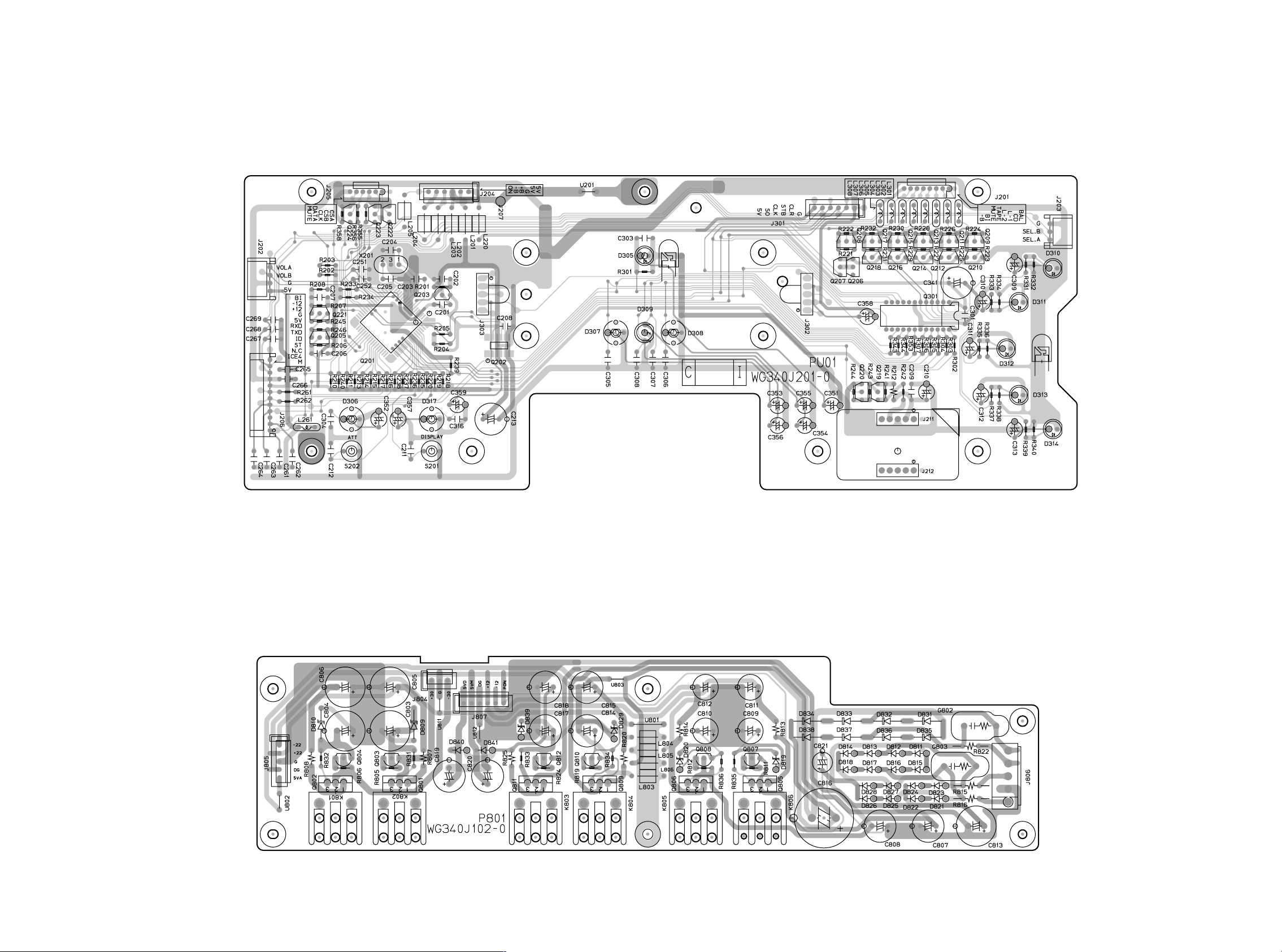
PU01
Q222-Q224
Q203Q221
Q205 Q202
Q201 D313 D314Q219D308D307
D305
D309
Q220
Q206-Q218 D310D311
Q301
D312
P801
D810 D809
Q804 Q803
Q802
15 16
Q801
D840 D841
D839
D829 D831-D838
Q810Q812
Q809Q811
D820 Q807Q808
D819
Q805Q806
D811-D818
D821-D828
Page 12

P261
D801
P851
D805 D806 D807 D808
D804D803D802
P891
PF01
P271
Q272
Q279
Q278
D271-D273
Q274-Q277
D275
D274Q273
PU51
PU61
PS71
D315
D316
PS01
P301
D301- D304
PU71
Q204
17 18
P251
Page 13

5. IC DATA
Q301:NJU3716
Q302:NJU3719
Pin Description
Block Diagram
Pin Assignment
Q526/Q529:WN8816
Pin Description
19
Page 14

LED Port Assignment
NJU3716 NJU3719
DATA SO DATA
LED1 LED2 LED3 LED4
f
e
a
g
b
c
d
D.P
Pin No. Data output pin NJU3716 Pin No. Data output pin NJU3719
*17 P1 NON *20 P1 LED3b
*19 P2 TAPE LED *21 P2 LED3c
*20 P3 LINE-2 LED *22 P3 LED3-DP
*21 P4 LINE-1 LED *23 P4 LED3d
*22 P5 SACD/CD LED *24 P5 LED3e
*23 P6 BALANCED LED *25 P6 LED3g
*1 P7 POWER LED *26 P7 LED3f
*2 P8 ATT LED *27 P8 LED3a
*3 P9 B-CH LED *28 P9 NON
*4 P10 A-CH LED *29 P10 LED1g
*5 P11 SYNK-RED LED *1 P11 LED2a
*7 P12 SYNK-GR LED *2 P12 LED2f
*8 P13 DISPLAY LED *3 P13 LED2g
*9 P14 LIGHT-A *4 P14 LED2e
*10 P15 LIGHT-B *5 P15 LED2d
*11 P16 NON *6 P16 LED2c
*12 SO *7 P17 LED2b
. *9 P18 LED4a
*10 P19 LED4f
*11 P20 LED4g
*12 P21 LED4e
*13 P22 LED4d
*14 P23 LED4c
*15 P24 LED4b
Q201:HD64F3664H
Pin Assignment
NCNCP22/TXD
48 47 46 45 44 43 42 41 40 39 38 37 36 35 34 33
49
NC
50
NC
NC
NC
51
52
53
54
55
56
57
58
59
60
61
62
63
64
1 2 3 4 5 6 7 8 910111213141516
NC
P14/
P15/
P16/
P17/ /TRGV
PB4/AN4
PB5/AN5
PB6/AN6
PB7/AN7
PB3/AN3
PB2/AN2
PB1/AN1
PB0/AN0
Note: Do not connect NC pins ( these pins are not connected to the internal circuitry).
NC
CC
AV
P21/RXD
P20/SCK3
X2
X1
P87
CL
V
P86
P85
H8/3664
Top view
TEST
P84/FTIOD
P83/FTIOC
P82/FTIOB
SS
V
OSC2
OSC1
P81/FTIOA
P80/FTCINCNC
CC
V
P50/
P51/
NC
NC
32
31
30
29
28
27
26
25
24
23
22
21
20
19
18
17
NC
NC
P76/TMOV
P75/TMCIV
P74/TMRIV
P57/SCL
P56/SDA
P12
P11
P10/TMOW
P55/
P54/
P53/
P52/
NC
NC
/
20
Page 15

Pin PORT Name I/O Function Description
33 N.C. --
34 N.C. --
35 (NMI) ICE4 Pull Up
36 P80(FTCI) N.C. I
37 P81(FTIOA) RC5 I Capture input port IR capture
38 P82(FTIOB) VOL-CLK O Output port WM8816 Clock
39 P83(FTIOC) VOL-DAT O Output port WM8816 Data Input / Output
40 P84(FTIOD) Master_H O Output port BUS control
41 P85 ICE1 For ICE connection
42 P86 ICE2 For ICE connection
43 P87 ICE3 For ICE connection
44 P20(SCK3) N.C. I
45 P21(RXD) RXD I Data input port SYSTEM Control bus input
46 P22(TXD) TXD O Data output port SYSTEM Control bus output
47 N.C. --
48 N.C. --
49 N.C. --
50 N.C. --
51 P14(IRQ0) DISP-CLR O Output port NJU3716,NJU3719
Clear signal input
52 P15(IRQ1) DISP-CLK O Output port NJU3716,NJU3719
Clock signal input
53 P16(IRQ2) DISP-DAT O Output port NJU3716,NJU3719
Serial data input
54 P17
(IRQ3/TRGV)
DISP-STB O Output port NJU3716,NJU3719
Strobe signal input
55 (PB4/AN4) N.C. I
56 (PB5/AN5) N.C. I
57 (PB6/AN6) N.C. I
58 (PB7/AN7) N.C. I
59 (PB3/AN3) DISPLAY I Input port L(SW ON)
60 (PB2/AN2) N.C. I
61 (PB1/AN1) ATT I Input port L(SW ON)
62 (PB0/AN0) ID Switch I Analog input port 1=4.5~5.0V
2=3.7~4.5V
3=2.9~3.7V
4=2.2~2.9V
5=1.4~2.2V
6=0.0~1.4V
63 N.C. --
64 N.C. --
Pin Description
Pin PORT Name I/O Function Description
1 N.C. --
2 N.C. --
3 (AVcc) AVcc I Analog power
4 (X2) X2 O Sub clock
5 (X1) X1 I Sub clock Connect to GND
6 (VCL) Vcl I Internal less voltage
power pin
7 (RES) RES I Reset pin
8 (TEST) TEST I Test pin Connect to GND
9 (VSS) GND I Ground
10 (OSC2) OSC2 O System clock
11 (OSC1) OSC1 I System clock
12 (Vcc) +5 I Power supply
13 P50(WKP0) Volume A I External Interrupt Req. Active H
14 P51(WKP1) Volume B I External Interrupt Req. Active H
15 N.C. --
16 N.C. --
17 N.C. --
18 N.C. --
19 P52(WKP2) Selector A I External Interrupt Req. Active H
20 P53(WKP3) Selector B I External Interrupt Req. Active H
21 P54(WKP4) Mute-1 O Output port L(MUTE ON)
22 P55
Mute-2 O Output port L(MUTE ON)
(WKP5/ADTRG)
23 P10(TMOW) Mute-B O Output port WM8816 Mute
24 P11 N.C. I
25 P12 N.C. I
26 (SDA) SDA I/O I2C data output port Serial data to
27 (SCL) SCL O I2C clock I/O port Serial clock to
28 P74(TMRIV) VOL-CSA O Output port WM8816 Chip Select
29 P75(TMCIV) VOL-CSB O Output port WM8816 Chip Select
30 P76(TMOV) Power
I External Interrupt Req. H(POWER OFF)
Off
31 N.C. --
32 N.C. --
21 22
AT24C04 EEPROM
AT24C04 EEPROM
Page 16

6. EXPLODED VIEW AND PARTS LIST
001D
007D
005D
5128
3X6( U)
003Dx2
013D
( 003B)
x6
5150
3X6( M)
x4
5128
3X8( M)
x4
921Gx4
057Bx2
( 006B)
041B
017D
5128
3X4( U)
x2
015D
5128
3X8( M)
x2
035B
( 010B)
x7
(007B)
(008B)
001B
FRONT PANEL ASSY.
5128
3X4( U)
5126
3X10( M)
P2 6 1
5150
3X8( M)
( 009B)
( 002B)
009D
x6
5128
3X6( U)
x6
x6
011B
052Bx2
020Dx2
914Gx2
5104
3X6( M)
x2
015B
027Bx2
5110
3X8( M)
x4
045Bx2
019Bx2
019Dx2
5128
3X6( M)
x2
048B
017B
5128
3X4( U)
P8 91
013B
026B
024B
( 004B)
5129
3X8( M)
x7
005D
5110
3X4( U)
x4
025B
023B
020Bx2
5128
3X6( M)
039Bx2
( 5128)
3X8( M)
x4
5126
3X8( M)
x2
5405
047Bx6
5128
3X4( U)
x2
P3 0 1
053Bx2
3( M)
x7
PU01
022B
5128
3X8( M)
SYMBOL STYLE
5104
5110
5126
5128
5129
5146
5150
5204
5405
002D
5128
3X8( M)
x4
PU61
030Bx4
049B
5128
3X4( U)
x4
5129
x2
3X8( B)
5128
3X8( M)
x2
037B
L002
5110
3X4( U)
x4
x4
T100
PARTS NAME
+F.H.M.SCREW
+B.H.M.SCREW
+B. H. TAP TI TE SCREW W/WASHER
+B. H. TAP T I TE SCREW( B TYPE)
+B. H. TAP T I TE SCREW(W/T . L . WASHER)
+B.H.M. SCREW(W/T.L.WASHER)
+F . H. TAP T I TE SCREW(B TYPE)
+H. H. T APT. BOLTS FL ANGE( S TITE)
TOOTHED L OCK WASHERS
5204
4X8( M)
L001
x8
WITH
5110
3X6( U)
x3
5405
4( M)
x8
P851
5146
3x6( M)
x2
PU51
5128
4X8( M)
5110
3X6( U)
x7
046Bx4
x3
008Gx10
5204
4X8( M)
x2
058Bx2
050B
024G
021Gx2
5129
3X8( B)
P25 1
055Bx4
021B
x7
MARK MATERI AL/ FINISH
(M)
STEEL/ COPPER
(U)
STEEL/ BLACK
(A),(B)
STEEL/ CHROMAT E
5110
3X6( U)
x4
PS0 1
5110
3X6( U)
x4
5146
3X6( M)
x1
5129
8( M)
3X
x2
023Gx3
x3
005G
904G
001K- 006K
P801
014G
020Gx2
012G
002Gx4
907Gx4
PF0 1
906G
PS7 1
5146
3X6( M)
x2
5128
3X6( B)
007Gx9
5110
3X6( U)
x4
902G
5110
3X6( U)
x4
x3
H01Kx12
018G
026G
5150
3X10( U)
x2
917G
x2
015G
5150
3X10( U)
x7
J001
5110
3X6( M)
5128
8( M)
3X
x2
P271
5128
3X8( M)
x2
919G
x2
5146
3X6( M)
x2
5128
3X6( B)
x2
5128
4X20( M)
x4
5128
3X8( M)
x2
001G
5405
4( M)
x4
W001
920Gx2
916Gx14
901G
5110
3X6( M)
x7
PH01
001K- 006K
5150
3X10( U)
x6
5150
3X8( M)
x8
5129
3X8( M)
x5
5126
3X8( M)
x2
5110
3X8( M)
x6
013K- 018K
x6
033Bx2
23 24
Page 17

POS.
NO
VERS.
COLOR
PART NO.
(FOR PCS)
DESCRIPTION
PART NO.
(MJI)
POS.
NO
VERS.
COLOR
PART NO.
(FOR PCS)
DESCRIPTION
PART NO.
(MJI)
001B 340J248510 FRONT PANEL ASSY 340 J2485 10
002B 340J248110 FRONT PANEL 340 J248 110
003B 340J063110 ESCUTCHEON LEFT 340 J0 63 11 0
004B 340J063120 ESCUTCHEON RIGHT 340J063120
006B 339J353110 RING FOR METER 339J 353110
007B 339J158010 WINDOW FOR METER 339J1 58010
008B 339J353120 RING FOR POWER SW. 339J35 3120
009B 340J355010 LENS FOR IR 340J35 50 10
010B 269J355010 LENS FOR INPUT SEL /ATT 269J 35 50 10
015B 339J270110 BUTTON FOR POWER SW. 339J270110
020B 340J270110 BUTTON FOR DISPLAY /ATT 340J27 0110
033B 340J154110 KNOB INPUT SEL /VOLUME 34 0J 154 11 0
001D 340J249110 SIDE PANEL LEFT 340J249 110
002D 340J249120 SIDE PANEL RIGHT 3 40 J2491 20
003D 340J063130 ESCUTCHEON 340 J0 63130
007D 339J257110 TOP LID 339J257110
013D 339J063130 ESCUTCHEON FOR TOP LID 33 9J 063130
015D 339J202010 NET FOR ESCUTCHEON 33 9J 20 20 10
002G 163J057220 LEG (CUPPER) 163J057220
906G 426T154010 KNOB FOR ID NO.SW. 426T154010
J001 YJ04002550 JACK AC INLET TYPE HF-301 YJ04002550
L001 /F nsp POWER TRANSF.
TS40701010
SURPER RING RT-75 FOR /F
L001 /N TS40701020 POWER TRANSF. TS40701020
L001 /U nsp POWER TRANSF. TS40701030
L002 FN 21010030 0.18H CHOKE COIL FN21010030
L003 FC 50160030 FERRITE CORE FOR W018 FC50160030
L004 FC 50160030 FERRITE CORE FOR W020 FC50160030
L005 FC 50160030 FERRITE CORE FOR W019 FC50160030
NOTE : "nsp" PART IS LISTED FOR REFERENCE ONLY, MARANTZ WILL NOT SUPPLY THESE PARTS.
PACKING
001T /F nsp USER GUIDE SC-7S1 /F 3 40J85 11 10
001T /N/U 340J851310 USER GUIDE SC-7S1 34 0J 85 13 10
T100 ZK340J0010 REMOTE CONTROLLER
ZK340J0010
RC-7S1SC
W001 /F nsp MAINS CORD FOR /F OFC 2P ZC01803130
W001 /N ZC01803080 MAINS CORD
ZC01803080
10A 250V 2P CLASS2
W001 /U nsp MAINS CORD 13A 125V UL/CSA ZC01802100
NOT STANDARD SPARE
PARTS
001S n sp PACKING CASE 340 J8 01 01 0
003S n sp CUSHION F 3 39 J8 09 01 0
004S n sp CUSHION R 339 J8 09 020
010S n sp PACKING CASE
340J805010
MASTER CARTON
W091 nsp CONNECTIVE CORD TCP8580
ZD01000910
REMOTE CABLE
25
Page 18

7. SERVICE MODE
1. To enter the Service Mode, press the POWER s witch with pressing the DISPLAY and ATT buttons on the main unit to switch
power ON, or when the remote code '166363' is received while power is ON.
2. The version number is displayed as '×××' on the 7-segment LED.
The Light-up LED is lit (other LEDs lit off).
"×××" means version ×.××.
3. Press the ATT button to light the LEDs one by one (except the Light-up LED which is always lit) , and 'LEd' is displayed.
4. Press the ATT button to light each 7-segment LED one by one.
All LEDs (including the Light-up LED) are lit off.
5. Press the ATT button to light all the 7-segment LEDs and the LEDs.
6. Press the ATT button to display the ID number.
If the ID number switch on the rear panel is changed, the displayed ID number also changes (polling at 250ms intervals).
7. Press the ATT button to display 'BUS', one second after followed by 'BOK' or 'BNG'.
'BNG' is displayed if the unit is unable to receive the command that has issued by the unit itself.
'BOK' is displayed if the unit is able to receive the command that has issued by the unit itself.
The circuit is designed to go through the command, so 'BOK' is displayed e ven if the remote cable is not connected. 'BNG'
is displayed when the cable is in a closed-loop and the unit is the Master , or when the cable is not connected and the unit
is a Slave.
8. Press the ATT button to display 'Uol'.
The display changes to 'Up' if the Volume knob is turned clockwise, and to 'dUn' if it is turned counter-clockwise.
9. Press the ATT button to display 'SEI'.
When the INPUT SELECTOR is changed the corresponding LED is lit.
10. Press the ATT button to display 'Att'.
The corresponding text is displayed for the operation buttons and knobs as shown below.
SW Key
Displayed
text
7Seg
Front Display DSP dSp
Front ATT ATT Att
RC BALANCE
RC SACD/CD
RC LINE-1
RC LINE-2
RC TAPE
RC Volume UP
RC Volume Down
RC ATT
RC Trim
RC EXIT
RC A-Trim Up
RC A-Trim Down
RC B-Trim Up
RC
RC
RC
RC
RC
RC
RC
RC
RC
RC
RC
RC
RC
RC
RC
rC
rC
rC
rC
rC
rC
rC
rC
rC
rC
rC
rC
rC
rC B-Trim Down
26
Page 19

SW Key
7Seg
Front Display DSP dSp
Front ATT ATT Att
RC BALANCE
RC SACD/CD
RC LINE-1
RC LINE-2
RC TAPE
RC Volume UP
RC Volume Down
RC ATT
RC Trim
RC EXIT
RC A-Trim Up
RC A-Trim Down
RC B-Trim Up
RC
RC
RC
RC
RC
RC
RC
RC
RC
RC
RC
RC
RC
RC
RC
rC
rC
rC
rC
rC
rC
rC
rC
rC
rC
rC
rC
rC
rC B-Trim Down
27
Page 20

[
[CD]
[
]
[
]
[
]
[
]
[
]
[
]
(toggle)
[
[
[
[
[
11. This completes all the tests. Press the DISPLAY and ATT buttons to return to Step1., or press the POWER switch to turn
power OFF. Note that the Service Mode is terminated if power is turned OFF at any point during steps 1. to 10.
When the Service Mode is terminated the memory is cleared and the system is initialized.
The Input Selector, Volume level, ATT level, and TRIM level are stored in memory, therfore use this Service Mode to
initialize the system.
[Microcomputer Initial Setup]
Input Selector: SACD/CD
Volume: -∞
TRIM setup value: +/-0dB (for channels A and B)
ATT setup value: -20dB
REMOTE COMMANDS TABLE
No. Key name RC code
1 BALANCED
2 SACD/CD
3 LINE-1
4 LINE-2
5 TAPE
6 VOLUME UP
7 VOLUME DOWN
8 ATT
9 TRIM SELECT
10 EXIT
11 A-TRIM UP
12 A-TRIM DOWN
13 B-TRIM UP
14 B-TRIM DOWN [Rch level-] 16 26 04
BALANCE]16 00 20
AUX 1
AUX 2
TAPE
VOL+
VOLMUTE
CH SEL]16 37 33
MENU OFF16 83
Lch level+]16 26 01
Lch level-]16 26 02
Rch level+]16 26 03
20 63
16 00 06
16 00 07
18 63
16 16
16 17
16 13
Operation details
Select balanced input terminal
Select SACD/CD input terminal
Select Line-1 input terminal
Select Line-2 input terminal
Select Tape input terminal
Master Volume UP
Master Volume DOWN
The value that subtracted the ATT value
from the Vol. value.
Press again to return to the original setup value.
Change TRIM Mode/TRIM setup unit.
Exit from TRIM Mode.
In TRIM mode: TRIM level UP
In TRIM mode: TRIM level DOWN
In TRIM mode: TRIM level UP
In TRIM mode: TRIM level DOWN
28
Page 21

REMOTE COMMANDS TABLE
No. Key name RC code
1 BALANCED [BALANCE] 16 00 20
2 SACD/CD [CD] 20 63
3 LINE-1 [AUX 1] 16 00 06
4 LINE-2 [AUX 2] 16 00 07
5 TAPE [TAPE] 18 63
6 VOLUME UP [VOL+] 16 16
7 VOLUME DOWN [VOL-] 16 17 Master Volume DOWN
8 ATT [MUTE] 16 13
(toggle)
9 TRIM SELECT [CH SEL] 16 37 33
10 EXIT [MENU OFF] 16 83
11 A-TRIM UP [Lch level+] 16 26 01
12 A-TRIM DOWN [Lch level-] 16 26 02
13 B-TRIM UP [Rch level+] 16 26 03
14 B-TRIM DOWN [Rch level-] 16 26 04 TRIM
BALANCED
SACD/CD
LINE-1
LINE-2
TAPE
Master Volume UP
Vol.
TRIM
Exit from TRIM
TRIM
TRIM
TRIM
ATT
/TRIM
TRIM UP
TRIM DOWN
TRIM UP
TRIM DOWN
29
Page 22

8. BUS SPECIFICATIONS
< Features >
This unit employs a bus system incorporating the 'e-Bus' (bi-directional pack et communications) concept, and is used f or control
of independent and system operation.
The Master unit controls all the bus sysytem.
The bus system provides for mutual recognition, with control commands and status inf ormation being sent and received between
units, thus allowing linked operation of multiple units.
When multiple Slave units are connected to the Master unit and power is switched ON, the system is set up (volume value,
functions) automatically, and setup for each Slave unit is therefore unnecessary.
The Master unit manages system operation when the ID number switch is set to [1]. Slave units are managed and controlled by
the Master when the ID number switch is set to [2] to [6].
Up to six units can be connected to the bus.
< Connections >
This bus system uses hardware relays for bus communications unrestricted by ON/OFF switching of multiple SC-7S1 power
supplies. The first and last units need not be directly connected, and units are connected by a single remote cable (Mini DIN
cable).
A slave unit can be added to the existing system an ywhere in the b us loop. ID numbers are not required to be set in the order of
the connection. The master can recognize the slave units regardless of the connection order of the ID numbers.
As the SC-7S1 bus system is unique, only SC-7S1s can be connected.
< Operation >
Only units in operation (power ON) are recognized and treated as e xisting units on the b u s . When power for a Slave unit is OFF
the hardware relay lets through the unit on the bus.
ID numbers are set with the ID number switches on the rear panel.
Button commands and remote commands received by the Master unit are transmitted to the sla v es depending on the command
content.
Commands from remote controller are received only by the Master unit (not by Slave units).
When the Master unit receives the command without any modification,the command is what has been transmitted b y the Master
itself to the bus upon power on, the Master assumes that no slave is connected and turns into stand alone operation.
RS-232C interface specifications (4800bps, 8 data bits, non-parity, 1 stop bit) is used as the specifications for this bus system
communication. For sound quality, communication occurs only when an operation is made. Polling is not used.
When multiple units are connected, the bus loop is established regardless of whether Sla ve unit power is ON or OFF. The only
case in which data is not returned to the Master unit is therefore when the connection is not phisically made.
The critical point fot service is whether or not data sent from TXD (pin 46 on the microcomputer) while Master unit power is ON
is received at RXD (pin 45 on the microcomputer). If there is a problem and data is lost, 'E12' error is displayed on the Master
unit. In this case, there ma y be a short circuit in the pattern or a part may be broken . Chec k the Data Flo w diagram and tr ace the
TXD data.
30
Page 23

31
Page 24

Remote Bus Connection
ID Numbers
Each unit is identified by a set ID number.
Each ID number is set by the user.
The unit with ID=1 is as the Master. ID=1 is also used for stand-alone (single-unit) operation.
If there are multiple units with the same ID number, connection error occurs and the error code is displayed,
The Master must be at the top in the bus connection.
ID numbers 2 to 6 connected after the Master are assumed to be for Slave units.
The Master controls all the Slave units connected to the bus.
Units with the ID numbers 2 to 6 cannot be operated independently. Those units require control signals from the Master unit for
operation. The last unit connected on the bus is referred to as the End Slave unit.
Outline of Bus Connections
END
ID=1
Master
OUT
IN
ID=2
Slave
Return
END
ID=1
Master
IN
OUT OUT OUT OUT OUT
IN
ID=2
Slave
ID=3
IN IN IN IN
Slave
ID=4
Slave
ID=5
Slave
ID=6
Slave
OUT
Return
The units are connected to the bus with the supplied remote cable (Mini DIN 8p).
The units are connected via photocouplers (Q273) and that is floated for sound quality, so a Hot and Cold pair is used for
communication.
The bus connection is established by receipt of the Return signal (dotted line) from the End Slave.
The circuit is designed to detect automatically if the unit is the End Slave. And if so the unit sends the Retur n signal to the
Master.
The circuit is designed that the bus connection is established even if power of a Slave unit is OFF.
Actually, the remote cable (dotted line arrow) from the End Slave to the Master is not necessary, the bus (solid line arrows) is
bidirectional so the Return signal returns to Master through the bus.
The ID numbers are displayed for approximately 3 seconds upon power ON, after that the volume level is displayed for
approximately 5 seconds. Mute is released approximately 8 seconds after power ON.
Bus communication begins at power ON. The Sync LEDs on the display are lit if there is no problem with the communication.
Master and Slave units are identified by the green and read sync LEDs respectively.
If making communication is impossible the Sync LED does not light and the error code is displayed.
As the Master unit controls all the units connected on the bus, Slave units cannot be operated directly (except for power
switches). Only the Master unit accepts commands from the remote controller.
32
Page 25

ID=1
Master
ID=1
Master
IN
END
IN
ID=2
Slave
OUT
Return
IN
ID=2
Slave
OUT OUT OUT OUT OUT
ID=3
IN IN IN IN
Slave
ID=4
Slave
ID=5
Slave
Return
END
ID=6
Slave
OUT
33
Page 26

Circuit Description
The P271 board is the bus connection interface board. The 8-pin Mini DIN cable is used for the reomote bus connection between
the units.
IN (J272)
Number Terminal Terminal description
1 IN-H Remote IN Hot
2 IN-C Remote IN Cold
3 Return-H Return Hot from End Slave
4 Return-C Return Cold from End Slave
5 M-G ND Master GND
6 M-G ND Master GND
7 +12V Relay drive +12V supplied from Master
8 -12V Relay drive -12V supp li ed from Master
OUT (J273)
Number Terminal Terminal description
1 OUT-H Remote OUT Hot
2 OUT-C Remote OU T Cold
3 Return-H Return Hot from End Slave
4 Return-C Return Cold from End Slave
5 Det ect End Slave detect
6 M-G ND Master GND
7 +12V Relay drive +12V supplied from Master
8 -12V Relay drive -12V supp li ed from Master
Signal 3 and 4 are Return signals from the End Slave to the Master, so the remote cab le connectiong from the End Sla ve to the
Master is not necessary.
The +12V (7) and -12V (8) are supplied from the Master, and drive the End rela y (L275) when the End Slav e is detected. M-GND
is also connected to Master GND as with the 12V power supply.
Relay L275 is switched ON when the unit is the End Slave. As this relay is driven from the Master, it is switched ON even if the
End Slave power is OFF.
Relays L273 and L274 are ON when the unit is set as the Master.
Relays L271 and L272 are ON when power is turned ON. This estab lishes the communications route e v en if Sla ve power is OFF.
The photocoupler Q273 is the interface which sends the signal input to J272 to the microcomputer . It is being floated for sound
quality.
End Slave Detection
The End Slave is detected from the voltage difference between OUT (J273) 5 and 6.
When a further slave is connected, OUT (J273) is connected to the IN (J272) of this unit.
As IN (J272) 5 and 6 are short-circuited, the transistor (Q277) and the End relay (L275) are switched OFF.
When a further slave is not connected, 5 and 6 are not short-circuited so the unit is detected as the End Slave. The transistor
(Q277) and the End relay (L275) are switched ON.
When the End relay (L275) is switched ON the circuit is s witched to send Return signal to the Master, so that the b us connection
is established.
ID
Set voltage
number
1 4.5 to 5.0V
2 3.7 to 4.5V
3 2.9 to 3.7V
4 2.2 to 2.9V
5 1.4 to 2.2V
6 0 to 1.4V
34
Page 27

1 IN-H Remote in Hot
2 IN-C Remote in Cold
3 Return-H
4 Return-C
5 M-GND
6 M-GND
7 +12V
8 -12V
1 OUT-H Remote OUT Hot
2 OUT-C Remote OUT Cold
3 Return-H
4 Return-C
5 Detect
6 M-GND
7 +12V
8 -12V
END Slave
END Slave
Master GND
Master GND
Master
Master
END Slave
END Slave
END Slave
Master
Master
Master
GND
Return Hot
Return Cold
+12V
-12V
Return Hot
Return Cold
+12V
-12V
ID
1
2
3
4
5
6
4.5
3.7
2.9
2.2
1.4
0
5.0V
4.5V
3.7V
2.9V
2.2V
1.4V
35
Page 28

Error Messages
Switch power OFF if any of the following error messages are displayed while multiple units are in use and connected to the bu s
via the remote terminal.
Error
Code
1 E02 Multiple units set for ID No.2.
2 E03 Multiple units set for ID No.3.
3 E04 Multiple units set for ID No.4.
4 E05 Multiple units set for ID No.5.
5 E06 Multiple units set for ID No.6.
6 E07 Communication between ID No.1 (Master)
and ID No.2 to 6 (Slave) impossible.
7 E08 Multiple units set for ID No.1 (Master). Change the ID number on the ID number
Meaning Me asures required
Change the ID number on the ID number
selector switch to avoid duplication.
Check IN and OUT, and make sure that the
bus connection cable is inserted correctly.
selector switch to avoid duplication.
36
Page 29

+5V
Master ON
Relay
END Relay
Power ON
Relay x 2
1
2
3
4
5
6
6
5
4
3
2
1
Master_H
ID
BUS IN
BUS OUT
+12V
M-GND
M-GND
Return-c
Return-H
IN-C
IN-H
+12V
M-GND
Detect
Return-C
Return-H
OUT-C
OUT-H
L274
-12V
+12V
Master ON
Relay
L273
Lo
Q277
L275
Q274
S274(ID SW)
Q275
Q273
L271
L271
L272
Q276
Hi
-12V
-12V
IN
OUT
Q201
40
45
46
S274
62
+5V
Master ON
Relay
END Relay
Power ON
Relay x 2
1
2
3
4
5
6
6
5
4
3
2
1
Master_H
ID
BUS IN
BUS OUT
+12V
M-GND
M-GND
Return-c
Return-H
IN-C
IN-H
+12V
M-GND
Detect
Return-C
Return-H
OUT-C
OUT-H
L274
-12V
+12V
Master ON
Relay
L273
Lo
Q277
L275
Q274
Q275
Q273
L271
L271
L272
Q276
Lo
-12V
- 12V
Q201
40
45
46
S274
62
+5V
Master ON
Relay
END Relay
Power ON
Relay x 2
1
2
3
4
5
6
6
5
4
3
2
1
Master_H
ID
BUS IN
BUS OUT
+12V
M-GND
M-GND
Return-c
Return-H
IN-C
IN-H
+12V
M-GND
Detect
Return-C
Return-H
OUT-C
OUT-H
L274
-12V
+12V
Master ON
Relay
L273
Hi
Q277
L275
Q274
Q275
Q273
L271
L271
L272
Q276
Lo
-12V
- 12V
Q201
40
45
46
S274
62
ID:2
ID:3
ID:1
IN
OUT
IN
OUT
MASTER
SLAVE
SLAVE
S274(ID SW)
S274(ID SW)
: OUT- H, IN- H (BUS IN/OUT)
: Return-H (BUS Return)
: Return-C (Master BUS GND)
: OUT-C, IN-C (Slave BUS GND)
BUS Loop
off
on
on
on
off
off
off
on
off
on
off
on
-12V
-12V
-12V
-12V
-12V
-12V
-12V
-12V
-12V
: +12V (END Relay Supply)
: -12V (END Relay Supply)
: M-GND (END Relay Detect GND)
Bus Connection System Data Flow
37
Page 30

9. ELECTRICAL PARTS LIST
ASSIGNMENT OF COMMON PARTS CODES.
RESISTORS
R : 1) GD05 × × × 140, Carbon film fixed resistor, ±5% 1/4W
R : 2) GD05 × × × 160, Carbon film fixed resistor, ±5% 1/6W
Examples ;
Resistance value
➀
0.1 Ω.... 001 10 Ω .... 100 1 kΩ .... 102 100 kΩ .... 104
0.5 Ω.... 005 18 Ω .... 180 2.7 kΩ .... 272 680 kΩ .... 684
1 Ω .... 010 100 Ω .... 101 10 kΩ .... 103 1 MΩ.... 105
6.8 Ω.... 068 390 Ω .... 391 22 kΩ .... 223 4.7 MΩ.... 475
Note : Please distinguish 1/4W from 1/6W by the shape of parts
used actually.
CAPACITORS
C : CERAMIC CAP.
3) DD1 × × × × 370, Ceramic capacitor
Examples ;
Tolerance (Capacity deviation)
➁
±0.25 pF.... 0
Tolerance of COMMON PARTS handled here are as follows :
C : CERAMIC CAP.
Examples ;
C : 5) ELECTROLY CAP. ( ), 6) FILM CAP. ( )
Examples ;
0.5 pF 5 pF .... ±0.25 pF
Capacity value
➂
0.5 pF .... 005 3 pF ....030 100 pF .... 101
1.5 pF .... 015 47 pF ....470 560 pF .... 561
4) DK16 × × × 300, High dielectric constant ceramic
Capacity value
➃
100 pF .... 101 1000 pF ....102 10000 pF .... 103
470 pF .... 471 2200 pF ....222
5) EA
Capacity value
➄
0.1 µF....104 4.7 µF ....475 100 µF....107
0.33 µF....334 10 µF ....106 330 µF ....337
Working voltage
➅
{
➂
{
{
➅
Resistance value
Disc type
Temp.coeff.P350 N1000, 50V
Capacity value
Tolerance
capacitor
Disc type
Temp.chara. 2B4, 50V
Capacity value
One-way lead type, Tolerance ±20%
Working voltage
Capacity value
2200 µF....228
➀
{
➁
±0.5 pF.... 1
±5%.... 5
6 pF 10 pF ....±0.5 pF
12 pF 560 pF .... ±5%
1 pF .... 010 10 pF ....100 220 pF .... 221
➃
× × × × × × 10, Electrolytic capacitor
{
➄
1 µF ....105 22 µF .... 226 1100 µF....118
6.3V....006 25 V ....025
10V....010 35V ....035
16V....016 50V ....050
NOTE ON SAFETY FOR FUSIBLE RESISTOR :
The suppliers and their type numbers of fusible resistors
are as follows;
1. KOA Corporation
Part No. (MJI) Type No. (KOA) Description
NH05 × × × 140 RF25S × × × × ΩJ(±5% 1/4W)
NH05 × × × 120 RF50S × × × × ΩJ(±5% 1/2W)
NH85 × × × 110 RF73B2A × × × × ΩJ(±5% 1/10W)
NH95 × × × 140 RF73B2E × × × × ΩJ(±5% 1/4W)
2. Matsushita Electronic Components Co., Ltd
Part No. (MJI) Type No. (MEC) Description
NF05 × × × 140 ERD-2FCJ × × × (±5% 1/4W)
RF05 × × × 140
NF02 × × × 140
RF02 × × × 140
Examples ;
{
Resistance value
ERD-2FCG
{
Resistance value
Resistance value
0.1 Ω.... 001 10 Ω .... 100 1 kΩ .... 102 100 kΩ .... 104
0.5 Ω.... 005 18 Ω .... 180 2.7 kΩ .... 272 680 kΩ .... 684
1 Ω .... 010 100 Ω .... 101 10 kΩ .... 103 1 MΩ.... 105
6.8 Ω.... 068 390 Ω .... 391 22 kΩ .... 223 4.7 MΩ.... 475
{
Resistance value
(0.1 Ω − 10 kΩ)
× × × (±2% 1/4W)
{
Resistance value
ABBREVIATION AND MARKS
ANT. : ANTENNA BATT. : BATTERY
CAP. : CAPACITOR CER. : CERAMIC
CONN. : CONNECTING DIG. : DIGIT AL
HP : HEADPHONE MIC. : MICROPHONE
µ-PRO : MICROPROCESSOR REC. : RECORDING
RES. : RESISTOR SPK : SPEAKER
SW : SWITCH TRANSF. : TRANSFORMER
TRIM. : TRIMMING TRS. : TRANSISTOR
VAR. : VARIABLE X’TAL : CRYSTAL
NOTE ON FUSE :
Regarding to all parts of parts code FS20xxx2xx, replace
only with Wickmann-Werke GmbH, Type 372 non glass type
fuse.
6) DF15 × × × 350 Plastic film capacitor
DF15 × × × 310 One-way type, Mylar ±5% 50V
DF16 × × × 310 Plastic film capacitor
Examples ;
Capacity value
➆
0.001 µF(1000 pF) ....... 102 0.1 µF....104
0.0018 µF........................ 182 0.56 µF....564
0.01 µF........................ 103 1 µF....105
0.015 µF........................ 153
: 1) The above CODES ( R , R , C , C and
NOTE
C ) are omitted on the schematic diagram in some
case.
2) On the occasion, be confirmed the common parts on
the parts list.
3) Refer to “Common Parts List” for the other common
parts (RI05, DD4, DK4).
➆
{
One-way type, Mylar ±10% 50V
Capacity value
NOTE ON SAFETY :
Symbol Fire or electrical shock hazard. Only original
parts should be used to replaced any part marked with
symbol . Any other component substitution (other
than original type), may increase risk of fire or electrical
shock hazard.
38
010728MIT
Page 31

POS.
NO
VERS.
COLOR
PART NO.
(FOR EUR)
DESCRIPTION
PART NO.
(MJI)
POS.
NO
VERS.
COLOR
PART NO.
(FOR EUR)
DESCRIPTION
PART NO.
(MJI)
P101 - MAIN UNIT
CIRCUIT BOARD
P101- CAPACITORS
CC11 nsp CER.50V DC 0.1µF +80%-20% DD38104010
CC31 nsp
ns p ELECT.220µF ±20% 25V ARA OA22702550
CC34 nsp
CC35 nsp
nsp ELECT.1000µF/25V ARA OA10802550
CC38 nsp
CC51 nsp ELECT.22µF ±20% 25V ARS OA22602540
CC52 nsp ELECT.22µF ±20% 25V ARS OA22602540
CC55 nsp ELECT.220µF ±20% 25V ARS O A22702540
CC56 nsp ELECT.220µF ±20% 25V ARS O A22702540
CC57 nsp CER.50V DC 0.1µF +80%-20% DD38104010
C405
OF55221590 FILM 220pF 200V OF 55 22 1590
C408
C409
ns p ELECT.22µF ±20% 25V ARS OA 22602540
C412
C415 OF55221590 FILM 220pF 200V ±5% FAS OF 5522159 0
C416 OF55221590 FILM 220pF 200V ±5% FAS OF 5522159 0
C417
ns p ELECT.22µF ±20% 25V ARS OA 22602540
C420
C423 OF55221590 FILM 220pF 200V ±5% FAS OF 5522159 0
C424 OF55221590 FILM 220pF 200V ±5% FAS OF 5522159 0
C425
ns p ELECT.22µF ±20% 25V ARS OA 22602540
C428
C431 OF55221590 FILM 220pF 200V ±5% FAS OF 5522159 0
C432 OF55221590 FILM 220pF 200V ±5% FAS OF 5522159 0
C433
ns p ELECT.22µF ±20% 25V ARS OA 22602540
C436
C439 OF55221590 FILM 220pF 200V ±5% FAS OF 5522159 0
C440 OF55221590 FILM 220pF 200V ±5% FAS OF 5522159 0
C441
ns p ELECT.22µF ±20% 25V ARS OA 22602540
C444
C451
ns p CER.50V DC 0.1µF +80%-20% DD 38104010
C460
C461
ns p ELECT.10µF 35V ARS OA10603540
C464
C505
OF55101590 FILM 100pF 200V ±5% FAS OF5 51 01590
C508
C509
ns p ELECT.22µF ±20% 25V ARS OA 22602540
C512
C513
ns p ELECT.470µF 25V ARS OA47702540
C516
C525
ns p ELECT.220µF ±20% 25V ARA OA22702550
C528
C529 nsp CER.50V DC 0.1µF +80%-20% DD 38104010
C530 nsp CER.50V DC 0.1µF +80%-20% DD 38104010
C533 OF15103540 FILM APSV 103J,
OF15103540
0.01µF(TP) 100V PP
NOTE : "nsp" PART IS LISTED FOR REFERENCE ONLY, MARANTZ WILL NOT SUPPLY THESE PARTS.
C535
OF55104580 FILM 0.1µF 100V ±5% FNS OF5 51 04580
C538
C539
ns p ELECT.22µF 25V ARA OA22602550
C542
C543
ns p ELECT.22µF ±20% 25V ARS OA 22602540
C550
C551
OF15102540 FILM 1000pF ±5% 100V APSV OF15 10 25 40
C554
P101- RESISTORS
RC01 nsp RES.22Ω ±5% 1/6W GG05220160
RC03 nsp RES.22Ω ±5% 1/6W GG05220160
RC05 nsp RES.22Ω ±5% 1/6W GG05220160
RC07 nsp RES.22Ω ±5% 1/6W GG05220160
RC09 nsp RES.22Ω ±5% 1/6W GG05220160
RC16 nsp RES.22Ω ±5% 1/6W GG05220160
RC17 nsp RES.22Ω ±5% 1/6W GG05220160
RC18 nsp RES.22Ω ±5% 1/6W GG05220160
RC21 nsp RES.22Ω ±5% 1/6W GG05220160
RC31
nsp RES.22Ω ±5% 1/6W GG05220160
RC38
RC51
nsp RES.10kΩ ±1% 1/4W GM11410020
RC58
RC59 nsp RES.100kΩ ±1% 1/4W GM11410030
RC60 nsp RES.100kΩ ±1% 1/4W GM11410030
RC61 nsp RES.226Ω ±1% 1/4W GM11422600
RC62 nsp RES.226Ω ±1% 1/4W GM11422600
RC63 nsp RES.22Ω ±5% 1/6W GG05220160
RC64 nsp RES.22Ω ±5% 1/6W GG05220160
RC73
nsp RES.2.26kΩ ±1% 1/4W GM11422610
RC80
R401
nsp RES.226kΩ ±1% 1/4W GM11422630
R404
R405
nsp RES.226Ω ±1% 1/4W GM11422600
R408
R409
nsp RES.15.4kΩ ±1% 1/4W GM11415420
R416
R417
nsp RES.22.6Ω ±1% 1/4W GM114226G0
R424
R425
nsp RES.100kΩ ±1% 1/4W GM11410030
R428
R433 nsp RES.22.6kΩ ±1% 1/4W GM11422620
R434 nsp RES.22.6kΩ ±1% 1/4W GM11422620
R435 nsp RES.226Ω ±1% 1/4W GM11422600
R436 nsp RES.226Ω ±1% 1/4W GM11422600
R437
nsp RES.2.26kΩ ±1% 1/4W GM11422610
R440
R441
nsp RES.100kΩ ±1% 1/4W GM11410030
R444
R449 nsp RES.22.6kΩ ±1% 1/4W GM11422620
39
Page 32

POS.
NO
VERS.
COLOR
PART NO.
(FOR EUR)
DESCRIPTION
PART NO.
(MJI)
POS.
NO
VERS.
COLOR
PART NO.
(FOR EUR)
DESCRIPTION
PART NO.
(MJI)
R450 nsp RES.22.6kΩ ±1% 1/4W GM11422620
R451 nsp RES.226Ω ±1% 1/4W GM11422600
R452 nsp RES.226Ω ±1% 1/4W GM11422600
R453
nsp RES.2.26kΩ ±1% 1/4W GM11422610
R456
R457
nsp RES.100kΩ ±1% 1/4W GM11410030
R460
R465 nsp RES.22.6kΩ ±1% 1/4W GM11422620
R466 nsp RES.22.6kΩ ±1% 1/4W GM11422620
R467 nsp RES.226Ω ±1% 1/4W GM11422600
R468 nsp RES.226Ω ±1% 1/4W GM11422600
R469
nsp RES.2.26kΩ ±1% 1/4W GM11422610
R472
R473
nsp RES.100kΩ ±1% 1/4W GM11410030
R476
R481 nsp RES.22.6kΩ ±1% 1/4W GM11422620
R482 nsp RES.22.6kΩ ±1% 1/4W GM11422620
R483 nsp RES.226Ω ±1% 1/4W GM11422600
R484 nsp RES.226Ω ±1% 1/4W GM11422600
R485
nsp RES.2.26kΩ ±1% 1/4W GM11422610
R488
R489
nsp RES.100kΩ ±1% 1/4W GM11410030
R492
R497
nsp RES.22.6kΩ ±1% 1/4W GM11422620
R500
R501
nsp RES.1.21kΩ ±1% 1/4W GM11412110
R504
R505
nsp RES.100Ω ±1% 1/4W GM11410000
R508
R509
nsp RES.681Ω ±1% 1/4W GM11468100
R516
R517
nsp RES.332Ω ±1% 1/4W GM11433200
R524
R525
nsp RES.100kΩ ±1% 1/4W GM11410030
R528
R529
nsp RES.226Ω ±1% 1/4W GM11422600
R532
R533
nsp RES.100kΩ ±1% 1/4W GM11410030
R536
R541 nsp RES.47Ω ±5% 1/6W GG05470160
R542 nsp RES.47Ω ±5% 1/6W GG05470160
R561
nsp RES.3.3MΩ ±5% 1/6W GD05335160
R568
R569
nsp RES.100Ω ±1% 1/4W GM11410000
R572
R573
nsp RES.15.4kΩ ±1% 1/4W GM11415420
R580
NOTE : "nsp" PART IS LISTED FOR REFERENCE ONLY, MARANTZ WILL NOT SUPPLY THESE PARTS.
R581
nsp RES.22.6Ω ±1% 1/4W GM114226G0
R588
R589
nsp RES.46.4Ω ±1% 1/4W GM114464G0
R592
R593
nsp RES.100Ω ±1% 1/4W GM11410000
R596
P101- RESISTORS(COMMON)
CARBON FILM FIXED RES.
±5% 1/6W : R001 R002
R201-R208
P101- SEMICONDUCTORS
DC01
nsp DIODE 1SS176,MA165, HD 20002000
DC10 1SS254 30V 0.1A
DC11
ns p DIODE 1D3 1A/200V HD 20002710
DC14
DC15 nsp DIODE 1SS176,MA165,
HD20002000
1SS254 30V 0.1A
DC16
HD20055100 SHOTTKY 11EQS10 1A 100V HD20055100
DC20
DC21 nsp DIODE 1SS176,MA165,
HD20002000
1SS254 30V 0.1A
DC51 nsp DIODE 1SS176,MA165,
HD20002000
1SS254 30V 0.1A
DC52 nsp DIODE 1SS176,MA165,
HD20002000
1SS254 30V 0.1A
DC53 nsp DIODE 1SS176,MA165,
HD20002000
1SS254 30V 0.1A
D501
ns p DIODE HSS81TD 150V 150MA HD20027010
D516 AXIAL TAPG.
D517 nsp DIODE 1SS176,MA165,
HD20002000
1SS254 30V 0.1A
D518 nsp DIODE 1SS176,MA165,
HD20002000
1SS254 30V 0.1A
QC11 HT110482B0 TRS.2SA1048 Y OR GR HT110482B0
QC12 HT324582B0 TRS.2SC2458 Y OR GR H T324582B0
QC51 HC10008610 IC OPA2604AP HC10008610
Q401
HT109702A0 TRS.2SA970 (GR) OR (BL) HT109702A0
Q404
Q405 HT322402A0 TRS.2SC2240 GR OR BL HT322402A0
HT322402A0 TRS.2SC2240 GR OR BL HT 322402A0
Q412 HT322402A0 TRS.2SC2240 GR OR BL HT322402A0
Q413
HT109702A0 TRS.2SA970 (GR) OR (BL) HT109702A0
Q416
Q417
HC10008610 IC OPA2604AP HC10008610
Q424
Q501
KH339J1010 UNIT HDAM-SA K H339J1010
Q508 (PH01 - PCB ASSY)
Q509
HT113492A0 TRS.2SA1349 GR BL DUAL TR. HT113492A0
Q512
40
Page 33

POS.
NO
VERS.
COLOR
PART NO.
(FOR EUR)
DESCRIPTION
PART NO.
(MJI)
POS.
NO
VERS.
COLOR
PART NO.
(FOR EUR)
DESCRIPTION
PART NO.
(MJI)
Q513
HT333812A0 TRS.2SC3381 GR OR BL H T333812A0
Q516
Q517
HT109702A0 TRS.2SA970 (GR) OR (BL) HT 109702A0
Q520
Q521
HT322402A0 TRS.2SC2240 GR OR BL H T322402A0
Q524
Q525
KH339J1010 UNIT HDAM-SA K H339J1010
Q528 (PH01 - PCB ASSY)
Q529 HC 10211990 IC WM8816 HC10211990
Q530 HC 10211990 IC WM8816 HC10211990
Q531 HC 10008610 IC OPA2604AP HC10008610
Q532 HC 10008610 IC OPA2604AP HC10008610
Q533
HT109702A0 TRS.2SA970 (GR) OR (BL) HT 109702A0
Q536
Q537
HT322402A0 TRS.2SC2240 GR OR BL H T322402A0
Q544
Q545
HT109702A0 TRS.2SA970 (GR) OR (BL) HT 109702A0
Q548
P101- MISCELLANEOUS
LC01
LY20240470 RELAY ED2-24 L Y20 240470
LC10
LC11 FC90050060 FERRIT BEADS (B-01-RT) F C9 00 50 060
LC21 LY20240470 RELAY ED2-24 LY2 0240470
LC51 LY20240470 RELAY ED2-24 LY2 0240470
LC52 LY20240470 RELAY ED2-24 LY2 0240470
LC53 LY20240470 RELAY ED2-24 LY2 0240470
L501 LY20240470 RELAY ED2-24 LY 20240470
L502 LY20240470 RELAY ED2-24 LY 20240470
L503 FC90050060 FERRIT BEADS (B-01-RT) FC 90 05 00 60
L504 FC90050060 FERRIT BEADS (B-01-RT) FC 90 05 00 60
P251 - VR
CIRCUIT BOARD
P251- RESISTORS(COMMON)
CARBON FILM FIXED RES.
±5% 1/6W : R210-R214
P251 - MISCELLANEOU
S251 SR02010070 ROTALY ENCODER 36PULSE
SR02010070
EC16B
P261 - FUNCTION SW.
CIRCUIT BOARD
P261 - CAPACITORS
C261 nsp CER.0.01µF DC50V +80%-20% DD 38103010
C262 nsp CER.0.01µF DC50V +80%-20% DD 38103010
P261 - MISCELLANEOUS
S261 SR 01120070 ROTARY SW.SRRSIC SR01120070
P271 - XLR IN/OUT
CIRCUIT BOARD
P271 - CAPACITORS
C271 nsp ELECT.10µF ±20% 25V RA-2 O A10602520
NOTE : "nsp" PART IS LISTED FOR REFERENCE ONLY, MARANTZ WILL NOT SUPPLY THESE PARTS.
C272
ns p CER.50V DC 0.1µF +80%-20% DD 38104010
C276
C280 n sp CER.50V DC 0.1µF +80%-20% DD38104010
C282 n sp CER.50V DC 0.1µF +80%-20% DD38104010
C282 n sp CER.50V DC 0.1µF +80%-20% DD38104010
C283 OF15102540 FILM 1000pF ±5% 100V APSV OF 15 10 25 40
C284 n sp CER.50V DC 0.1µF +80%-20% DD38104010
C285 OF15102540 FILM 1000pF ±5% 100V APSV OF 15 10 25 40
C286 n sp CER.50V DC 0.1µF +80%-20% DD38104010
C287 OF15102540 FILM 1000pF ±5% 100V APSV OF 15 10 25 40
C288
ns p CER.50V DC 0.1µF +80%-20% DD 38104010
C292
P271 - RESISTORS
R275 nsp RES.22Ω ±5% 1/6W GG05220160
R278 nsp RES.22Ω ±5% 1/6W GG05220160
R279 nsp RES.22Ω ±5% 1/6W GG05220160
R285 nsp RES.22Ω ±5% 1/6W GG05220160
P271- RESISTORS(COMMON)
CARBON FILM FIXED RES.
±5% 1/6W : R215-R229
P271 - SEMICONDUCTORS
D271 HD20055100 SHOTTKY 11EQS10 1A 100V HD20055100
D272 HD20055100 SHOTTKY 11EQS10 1A 100V HD20055100
D273 nsp DIODE 1SS176,MA165,
HD20002000
1SS254 30V 0.1A
D274 nsp DIODE 1SS176,MA165,
HD20002000
1SS254 30V 0.1A
D275 nsp DIODE 1SS176,MA165,
HD20002000
1SS254 30V 0.1A
Q272 HT110482B0 TRS.2SA1048 Y OR GR HT110482B0
Q273 HW10006320 PHOTO CUPLER PC-817 1PAIR HW10006320
Q274 HT110482B0 TRS.2SA1048 Y OR GR HT110482B0
Q275 BA20001000 DIG.TRS.DTC114ES/UN4211
BA20001000
10K,10K
Q276 HT110482B0 TRS.2SA1048 Y OR GR HT110482B0
Q277 BA20001000 DIG.TRS.DTC114ES/UN4211
BA20001000
10K,10K
Q278 HT324582B0 TRS.2SC2458 Y OR GR H T324582B0
Q279 HT110482B0 TRS.2SA1048 Y OR GR HT110482B0
P271 - MISCELLANEOUS
J272 YJ11000500 JACK 8PIN H-TYPE
YJ11000500
TCS7927-18-401
J273 YJ11000500 JACK 8PIN H-TYPE
YJ11000500
TCS7927-18-401
L271
LY20240500 RELAY NA-24WK 2T 24V LY20240500
L275
L276 F C90090010 FERRITE CORE ZBF503D-00TA FC90090010
S271 SS02021610 SLIDE SW.SSSU022-S06N1 SS 02 02 16 10
P301 - 7SEG LED
CIRCUIT BOARD
P301 - CAPACITORS
C302 n sp CER.CERMIC 0.1µF Z 50V DA 17 10 41 10
C339 nsp CER.10000pF DA171 03 11 0
C340 nsp CER.10000pF DA171 03 11 0
41
Page 34

POS.
NO
VERS.
COLOR
PART NO.
(FOR EUR)
DESCRIPTION
PART NO.
(MJI)
POS.
NO
VERS.
COLOR
PART NO.
(FOR EUR)
DESCRIPTION
PART NO.
(MJI)
P301- RESISTORS(COMMON)
CARBON FILM FIXED RES.
±5% 1/6W : R230-R246
R251-R254 R261 R262
R308-R330
P301 - SEMICONDUCTORS
D301
HQ10104060 DISPLAY UNIT TLS336T HQ10104060
D304
Q302 HC 10142090 IC NJU3719L HC10142090
P801 - POWER SUPPLY
CIRCUIT BOARD
P801 - CAPACITORS
C803
ns p ELECT.470µF ±20% 25V ARA OA47702550
C806
C807 nsp ELECT.470µF 25V ±20% RA-2 OA 47702520
C808 nsp ELECT.470µF 25V ±20% RA-2 OA 47702520
C809
ns p ELECT.220µF ±20% 25V RA-2 OA 22702520
C812
C813 nsp ELECT.470µF ±20% 25V ARA OA47702550
C814 nsp ELECT.100µF 25V ARA O A10702550
C815 nsp ELECT.100µF 25V ARA O A10702550
C816 nsp ELECT.6800µF 16V RA2 TYPE OA 68801620
C817 nsp ELECT.470µF 25V ±20% RA-2 OA 47702520
C818 nsp ELECT.470µF 25V ±20% RA-2 OA 47702520
C819 nsp ELECT.1000µF 10V ±20% RA-2 OA 10801020
C820 nsp ELECT.1000µF 10V ±20% RA-2 OA 10801020
C821 nsp ELECT.1µF ±20% 50V RA-2 O A10505020
P801 - RESISTORS
R807 nsp RES.2.2Ω ±5% 1/6W GG05022160
R808 nsp RES.2.2Ω ±5% 1/6W GG05022160
R813 nsp RES.3.3Ω ±5% 1/6W GG05033160
R814 nsp RES.3.3Ω ±5% 1/6W GG05033160
R815 nsp RES.1Ω ±5% 1/4W GG05010140
R816 nsp RES.1Ω ±5% 1/4W GG05010140
R820 nsp RES.3.3Ω ±5% 1/6W GG05033160
R822 nsp RES.1Ω ±5% 1/4W GG05010140
R825 nsp RES.3.3Ω ±5% 1/6W GG05033160
P801- RESISTORS(COMMON)
CARBON FILM FIXED RES.
±5% 1/6W : R271-R274 R276
R277 R280-R284 R286
P801 - SEMICONDUCTORS
D809 HD30012010 ZENER HZ24-2L HD30012010
D810 HD30012010 ZENER HZ24-2L HD30012010
D811
HD20055100 SHOTTKY 11EQS10 1A 100V HD20055100
D818
D819 HD31301000 ZENER 13V EQUIVALENT H D31301000
D820 HD31301000 ZENER 13V EQUIVALENT H D31301000
D821
HD20055100 SHOTTKY 11EQS10 1A 100V HD20055100
D828
D829 HD30621000 ZENER 6.2V EQUIVALENT HD30621000
D831
nsp DIODE 21DQ10 HD20059100
D838
D839 HD30751000 ZENER 7.5V EQUIVALENT HD30751000
NOTE : "nsp" PART IS LISTED FOR REFERENCE ONLY, MARANTZ WILL NOT SUPPLY THESE PARTS.
D840 n sp DIODE 1D3 1A/200V HD20002710
D841 n sp DIODE 1D3 1A/200V HD20002710
Q801 HT41415100 TRS.2SD1415 HT41415 10 0
Q802 HT21020100 TRS.2SB1020 HT21020 10 0
Q803 HF202461C0 F.E.T.2SK246 (GR) H F202461C0
Q804 HF202461C0 F.E.T.2SK246 (GR) H F202461C0
Q805 HT41415100 TRS.2SD1415 HT41415 10 0
Q806 HT21020100 TRS.2SB1020 HT21020 10 0
Q807 HF202461C0 F.E.T.2SK246 (GR) H F202461C0
Q808 HF202461C0 F.E.T.2SK246 (GR) H F202461C0
Q809 HT41415100 TRS.2SD1415 HT41415 10 0
Q810 HF202461C0 F.E.T.2SK246 (GR) H F202461C0
Q811 HT41415100 TRS.2SD1415 HT41415 10 0
Q812 HF202461C0 F.E.T.2SK246 (GR) H F202461C0
P801 - MISCELLANEOUS
G802 BF47400020 COMP.0.47µF+6.8Ω
BF47400020
RFD2B474K
G803 BF47400020 COMP.0.47µF+6.8Ω
BF47400020
RFD2B474K
L804 F C90050060 FERRIT BEADS (B-01-RT) FC 90 05 00 60
L805 F C90050060 FERRIT BEADS (B-01-RT) FC 90 05 00 60
L806 F C90050060 FERRIT BEADS (B-01-RT) FC 90 05 00 60
P851 - FILTER
CIRCUIT BOARD
P851 - CAPACITORS
C801 nsp ELECT.10000/50V O A10905010
C802 nsp ELECT.10000/50V O A10905010
P851 - RESISTORS
R826 nsp RES.1Ω ±5% 1/4W GG05010140
R827 nsp RES.1Ω ±5% 1/4W GG05010140
R828 nsp RES.1Ω ±5% 1/4W GG05010140
P851 - SEMICONDUCTORS
D801
nsp DIODE 21DQ10 HD20059100
D808
P851 - MISCELLANEOU
G801 BF47400020 COMP.0.47µF+6.8Ω
BF47400020
RFD2B474K
P891 - POWER SW.
CIRCUIT BOARD
P891 - CAPACITOR
C891 n sp FILM 0.01µF ±20% 250V AC DF7710 35 00
P891 - MISCELLANEOU
S891 SP01010830 PUSH SW. POWER
SP01010830
TV-8 UL.CSA
PF01 - FUSE CIRCUIT BOARD
PF01 - MISCELLANEOUS
F871 /F/U nsp FUSE 2A 125V UL,CSA,
FS10200350
MITI TYPE FBT
F871 /N FS10050850 FUSE 500mA 250V BS LISTED F S100508 50
PH01 - NEW MDAM
CIRCUIT BOARD
PH01- RESISTORS(COMMON)
CARBON FILM FIXED RES.
±5% 1/6W : R287-R290 R292
42
Page 35

POS.
NO
VERS.
COLOR
PART NO.
(FOR EUR)
DESCRIPTION
PART NO.
(MJI)
POS.
NO
VERS.
COLOR
PART NO.
(FOR EUR)
DESCRIPTION
PART NO.
(MJI)
PH01 - SEMICONDUCTORS
DH01
nsp DIODE 1SS176,MA165, HD 20002000
DH04 1SS254 30V 0.1A
QH01 HT109702A0 TRS.2SA970 (GR) OR (BL) HT109702A0
QH02 HT322402A0 TRS.2SC2240 GR OR BL HT 322402A0
QH03 HT109702A0 TRS.2SA970 (GR) OR (BL) HT109702A0
QH04 HT322402A0 TRS.2SC2240 GR OR BL HT 322402A0
QH05 HT322402A0 TRS.2SC2240 GR OR BL HT 322402A0
QH06 HT109702A0 TRS.2SA970 (GR) OR (BL) HT109702A0
PH01 - MISCELLANEOUS
JH01 YP07002860 PLUG IMSA-1068-06A YP07 00 28 60
JH02 YP07002850 PLUG IMSA-1068-05-T YP07 0028 50
PS01 - XLR INPUT
CIRCUIT BOARD
PS01- RESISTORS(COMMON)
CARBON FILM FIXED RES.
±5% 1/6W : R293 R294 R295
R301 R302
PS01 - MISCELLANEOU
S274 SR 02060190 SRRM ROTARY SW. SR0 20 60 190
PS71 - MODE SW
CIRCUIT BOARD
PS71 - MISCELLANEOU
S273 S S02021610 SLIDE SW.SSSU022-S06N1 SS0 20 21 61 0
PU01 - µ-COM
CIRCUIT BOARD
PU01 - CAPACITORS
C201 nsp CER.50V DC 0.1µF +80%-20% DD38104010
C202 nsp CER.50V DC 0.1µF +80%-20% DD38104010
C203 nsp CER.50V DC 0.1µF +80%-20% DD38104010
C204 nsp CER.30pF ±5% CH 50V BLK DD15300300
C205 nsp CER.30pF ±5% CH 50V BLK DD15300300
C206
ns p CER.50V DC 0.1µF +80%-20% DD 38104010
C209
C210 nsp ELECT.22µF ±20% 25V RA-2 OA22602520
C211 nsp CER.50V DC 0.1µF +80%-20% DD38104010
C212 nsp CER.50V DC 0.1µF +80%-20% DD38104010
C213 nsp ELECT.470µF ±20% 10V RA-2 OA 47701020
C251 nsp CER.0.01µF DC50V +80%-20% DD 38103010
C252 nsp CER.0.01µF DC50V +80%-20% DD 38103010
C261
nsp CER.10000pF DA1 71 03110
C269
C301
ns p CER.50V DC 0.1µF +80%-20% DD 38104010
C308
C309
ns p ELECT.10µF ±20% 25V RA-2 OA10602520
C313
C316 nsp CER.50V DC 0.1µF +80%-20% DD38104010
C341 nsp ELECT.470µF ±20% 10V RA-2 OA 47701020
C351
ns p ELECT.10µF ±20% 25V RA-2 OA10602520
C359
PU01 - RESISTOR
R212 nsp RES.22Ω ±5% 1/6W GG05220160
NOTE : "nsp" PART IS LISTED FOR REFERENCE ONLY, MARANTZ WILL NOT SUPPLY THESE PARTS.
PU01- RESISTORS(COMMON)
CARBON FILM FIXED RES.
±5% 1/6W : R303-R344 R353
R355 R356 R547-R551 R805
R806 R811 R812 R819 R824
R831-R836 RC11-RC15 RH01
PU01 - SEMICONDUCTORS
D305 HI10040080 L.E.D.SELU1E10CXM-S BLUE H I10040080
D306 HI10062320 L.E.D.LT3D8B RED 3O HI10062320
D307 HI10062320 L.E.D.LT3D8B RED 3O HI10062320
D308 HI10062320 L.E.D.LT3D8B RED 3O HI10062320
D309 HI10043080 L.E.D.SML11516C HI 10043080
D310
HI10040080 L.E.D.SELU1E10CXM-S BLUE HI 10040080
D314
D317 HI10062320 L.E.D.LT3D8B RED 3O HI10062320
Q201 *HS340JH0R IC HD64F3664H FLASH *HS340JH0R
Q202 HC10033990 IC AT24C04N-10SI-2.5 HC10033990
Q203 HC10098550 IC PST600D-2 RESET TAPING HC 10098550
Q205 HT324582B0 TRS.2SC2458 Y OR GR H T324582B0
Q206 BA20001000 DIG.TRS.DTC114ES/UN4211
BA20001000
10K,10K
Q207 BA20001000 DIG.TRS.DTC114ES/UN4211
BA20001000
10K,10K
Q208 HT110482B0 TRS.2SA1048 Y OR GR HT110482B0
Q209 HT110482B0 TRS.2SA1048 Y OR GR HT110482B0
Q210 BA20001000 DIG.TRS.DTC114ES/UN4211
BA20001000
10K,10K
Q211 HT110482B0 TRS.2SA1048 Y OR GR HT110482B0
Q212 BA20001000 DIG.TRS.DTC114ES/UN4211
BA20001000
10K,10K
Q213 HT110482B0 TRS.2SA1048 Y OR GR HT110482B0
Q214 BA20001000 DIG.TRS.DTC114ES/UN4211
BA20001000
10K,10K
Q215 HT110482B0 TRS.2SA1048 Y OR GR HT110482B0
Q216 BA20001000 DIG.TRS.DTC114ES/UN4211
BA20001000
10K,10K
Q217 HT110482B0 TRS.2SA1048 Y OR GR HT110482B0
Q218 BA20001000 DIG.TRS.DTC114ES/UN4211
BA20001000
10K,10K
Q219 HT110482B0 TRS.2SA1048 Y OR GR HT110482B0
Q220 HT324582B0 TRS.2SC2458 Y OR GR H T324582B0
Q221 HT324582B0 TRS.2SC2458 Y OR GR H T324582B0
Q222 BA20001000 DIG.TRS.DTC114ES/UN4211
BA20001000
10K,10K
Q223 BA20001000 DIG.TRS.DTC114ES/UN4211
BA20001000
10K,10K
Q224 BA20001000 DIG.TRS.DTC114ES/UN4211
BA20001000
10K,10K
Q301 HC10165090 IC NJU3716L HC10165090
PU01 - MISCELLANEOUS
L201
FC90050060 FERRIT BEADS (B-01-RT) FC 90050 06 0
L205
L220 F C90050060 FERRIT BEADS (B-01-RT) FC9 00 500 60
L261 F C90090010 FERRITE CORE ZBF503D-00TA FC90090010
L301
FC90090010 FERRITE CORE ZBF503D-00TA FC90090010
L308
S201 SP01013370 PUSH SW.EVQ11L05R H/
SP01013370
5MM,160GF
43
Page 36

POS.
NO
VERS.
COLOR
PART NO.
(FOR EUR)
DESCRIPTION
PART NO.
(MJI)
S202 S P01013370 PUSH SW.EVQ11L05R H/
SP01013370
5MM,160GF
X201 FQ 08004010 SERAMIC VIB.CRYSTAL
FQ08004010
8.0MHZ (MT) TAPING
PU51 - L LED CIRCUIT BOARD
PU51 - CAPACITOR
C314 nsp CER.50V DC 0.1µF +80%-20% DD38104010
PU51- RESISTORS(COMMON)
CARBON FILM FIXED RES.
±5% 1/6W : RH02
PU51 - SEMICONDUCTOR
D315 HI1 0040080 L.E.D.SELU1E10CXM-S BLUE HI10040080
PU61 - R LED CIRCUIT BOARD
PU61 - CAPACITOR
C315 nsp CER.50V DC 0.1µF +80%-20% DD38104010
PU61- RESISTORS(COMMON)
CARBON FILM FIXED RES.
±5% 1/6W : RH03
PU61 - SEMICONDUCTORS
D316 HI1 0040080 L.E.D.SELU1E10CXM-S BLUE HI10040080
PU71 - IR SENSOR
CIRCUIT BOARD
PU71 - SEMICONDUCTOR
Q204 HW10004210 PHOTO UNIT RPM6936-V4 HW10004210
NOTE : "nsp" PART IS LISTED FOR REFERENCE ONLY, MARANTZ WILL NOT SUPPLY THESE PARTS.
44
 Loading...