

Marantz 4270 Owners Manual
Model
4270
Stereo
~
MARANTZ
A WHOLLY·OWNED SUBSIDIARY OF SUPERSCOPE INC., SUN VALLEY, CALIFORNIA 91352
CO.,
INC.·P.O
. BOX
99·SUN
R
VALLEY,
CALIFORNIA·91352
2+
Quadradial
Receiver
4
WA
R A
All parts of MARAN TZ
guaranteed for a period
date
of purchase, exce
guaranteed for NINETY DAYS fr o m
purchase,
produ
electron
period of
the cab inetry Is guara
defects on ly, for a period of TWO
dat
necessary
charge during the above sta ted periods. T he
conditions of th is Warranty, and the
responsibilitY
under this War;anty,
an
the original, registered
transmitted
Box 99 , Su n Valley, California 91 352, not later
than
are
MARANTZ Service
product
COMPANY, INC., or
Serv
prepaid.
shipped in its original pack age. No accessories
should
accessories are s
MARANTZ COMPANY, INC. shall have no
liability whatsoever for loss of
such accessories,
purchase was made wit hin the United States of
America.
shipme nt is made by
MARANTZ Service
the
parts exchange are
Warranty , MARAN TZ COMPANY. INC. will
prepay return shi pping charges, pr ovided t hat such
return
located
and
except
cts are guaranteed .as f
ic
compo
THRE
e of pu rchase.
In
the
par
1,
The
authorized
2,
The
The
3.
to
TEN DAYS
4.
The
effected
iceStet
6. This Warranty shall be valid only if
United
by
5. If it becomes necessary to
or
ion, all shipping charges must be fullv
If
the
be shipped
The
Stat
shipment is to be mad e
wit
hin the
for
nents are fully
E YEARS from
ntee
event
that
ts and labo r will be furnis hed free of
of
MARA NTZ COMPANY, INC.
are
purchase must have
MARANTZ dealer.
Warranty
owner
Warranty Registration Card must be
MARAN
Warranty will
any
ent
IZ
from
date
anyone
Station.
defective part to MARANTZ
to
ire inst
with
hipp
ed with the
nor
for
Warr
anty
Station
es.
If
the
within
United
produ
of
THREE
pt
for
spe
aker products.
ollow
d against
service is requ ired, all
as follows:
extends
of the p rod uct.
COMPANY, INC., P. O.
of purchase. .
become
other
an
aut
rume
the
the
safe-return th ereof.
shall not appl y unless
the
from
requested
States.
cts are fully
YEARS
tubes
which are
date
s: all speaker and
guaranteed
date
only
than
horized MARANTZ
nt is
prod uct. If
or
pur
the t
Speaker
of purchase;
manufacturing
YEARS
exte
nt
been
made
in favor of
void if repairs
an
authorized
send
sent,
it
must
product.
damage to any
chaser to the
a point within
repairs and/or
erm
s of this
to
an address
from
for a
from
of the
from
this
be
any
the
of
7. This
Nunt>er has been
W
arranty
been
co
nnec ted or operated in
ctions
instru
INC. This Warrant y shall a lso be void if the
prod
uct
which MARANTZ COMPANY, INC. believes has
affected
8. MARANTZ COMPANY, INC. shall have
no liability whatsoever for co nseq uential da mages.
The sole responsibility of MARANTZ COMPANY,
under
INC.
repair of the prod
the sole discret ion of MARANTZ COMPA NY,
INC.
9. This Wa
furnishings of labor or par ts for user mainte nance,
as the same is described in the instructi on
handbook
or
10. This Warranty is valid only
to
repairs effected by an au t hor ized MARA NTZ
Station
Service
11.
APPLICABLE
DISCLAIMER OF WARRANTY,
IMPLI
MERCHANTABILITY OR FITNESS WITH
RESPECT TO THIS PRODUCT, NOR ARE
THERE
EXTEND BEYOND THE PROVISIONS OF
THIS
WA RR ANTY.
CHEC K·UPS AR E
WARRANTY .
12
. MARANTZ COMPANY, INC. reserves
the right to
i
mprovements
obligat ion to include these changes in any
products
TO
THIS WARRANTY.
WARRANTY
MARANTZ COMPANY, INC., P.O. BOX 99,
SUN VALLEY,
LATER THAN TEN DAYS FOLLOWING THE
DATE OF PURCHASE.
Warranty
shall
not
furnished by MARANTZ COMPANY,
has been
the
EXCEPT TO THE
ANY O
theretofore
PROTECT
altered
stability
this Warranty sha ll
rranty
furnished with this pro
.
ED
THER
make
upo n its
REGISTRATION
CALIFORNIA
is void if
altered
apply
or
uct,
LAW
WARRANTY
NOT
chariges .ln design
manufac
YOUR RIGHTS
FILL
or removed. Thi s
if
the
product
accordance
or repaired in any way
reliability of
or replacement thereo f ,in
does
WARRANTIES WHICH
ORDINAR
INCLUDED IN
prod
t ured.
OUT AND MAIL
the
be
limited to
not include the
duct,
with
EXTENT
PRECLUDES
THERE
Y PERIODIC
ucts without
CARD
91352
the
Serial
has
not
with the
product.
the
manu
respect
THAT
IS NO
O F
THIS
and/or
any
UNDER
THE
TO
, NOT
al
A
PURCHASE
'S
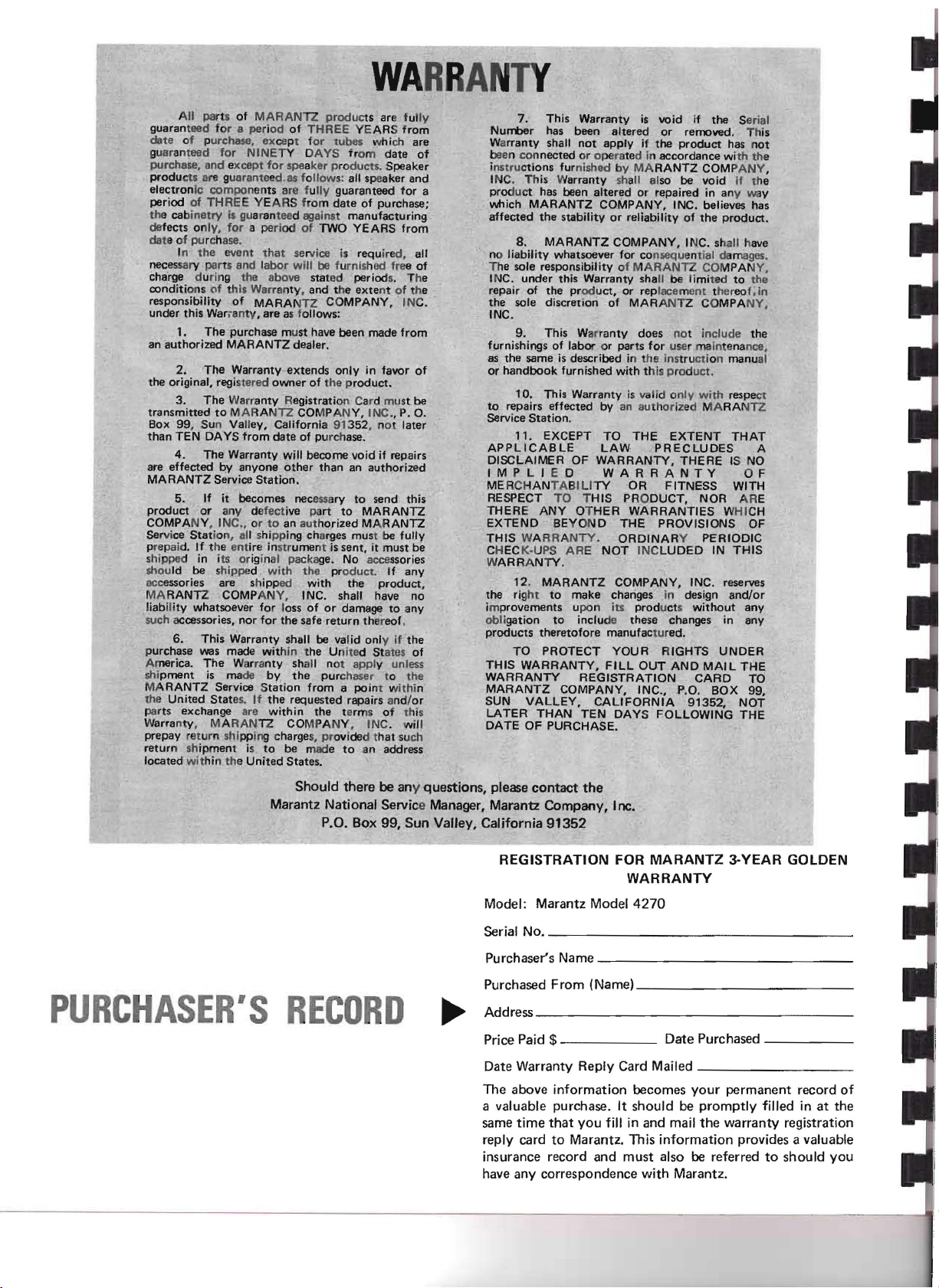
Should there be any questions, please
contact
the
Marantz National Service Manager, Marantz Company, Inc.
P.O. Box 99, Sun Valley, California
91352
REGISTRATION FOR
Model: Marantz Model
Serial No. _
Purchaser's Name _
Purchased From (Name) _
Address _
RECD
0
~
Price Paid
$
------
Date Warranty Reply Card Mailed _
The above information becomes
a valuable purchase. It should be promptly filled in at the
same
time
that
you fill in and mail
reply card to Marantz. This information provides a valuable
insurance record and must also be referred to should you
have any correspondence with Marantz.
MARANTZ
3-YEAR
WARRANTY
4270
Date Purchased - _
your
permanent record of
the
warranty registration
GOLDEN
TABLE
Connecting the 4270
Source Devices
Remote Speakers
Speaker Phasing
Speaker Placement
Front
Panel Features
Mode Switch
Dimension
SQ Decoder
Balance Controls
Selector Switch
Bass,
Mid
Monitor
Monitor
Main and Remote Spkr Switches
Power Switch
Front
and Rear Phones Jacks
Loudness
Filter
Hi
Tuning Meter
Tuning
FM Muting Switch
Volume
Dolby
Record Level
Play Cal.
400Hz Tone Switch
OF
and Treble Controls
Switch
Switch
Switch
Switch
(L)
(R)
CONT
for
Tape 1!Tape 2
for
Tape/Source
(L)
(R)
EN
TS
10
10
10
10
10
10
8
9
9
9
9
9
9
9
8
8
8
8
8
8
2
4
4
5
5
7
7
External Decoder Connection
Tape Recording
Basic
Dolby
Dolby
Procedure
Procedure
Use
Broadcasts
FM De-Emphasis Switch
Dolby
Technical Description
General
Functional Description
Frond End
IF
Stages
Limiter
FM Stereo Demodulator
Muting
AM Tuner
Phono
Selector Switch
Monitor
Monitor
Tone Control
Power
General Requirements
Installation
Service Notes
Process
Calibration
for
Playback Calibration
for
Record Calibration
of
the
Dolby
Mode Chart
Circuit
Amplifiers
(Tape/Source) Switch
(Tape 1 or 2) Switch
Amplifier
of
System on FM
Walnut Cabinet
13
13
14
14
14
15
16
16
16
18
18
18
18
18
18
18
18
18
19
19
19
19
19
19
19
20
20
Rear
Panel
Features
Phono Jacks
AUX
CD-4/
Tape
Out
Jacks
FM Antenna Terminals
AM Antenna Terminal
FM Quadradial
FM De-Emphasis Switch
Dolby
Muting Level Control 12
Power Mode Switch 12
Pre Out, Main In Jacks 12
Connecting an External
Rear Channels 12
Connecting an External
Front
Chassis
Main and Remote Speakers
Connection
AC Convenience Outlets
Remote Control
Jacks
Monitor
FM Preset Level Controls 12
Channels
Ground Binding Post
In and Tape
Output
to
AC
Outlet
Monitor
Jack 12
Amplifier
Amplifier
for
for
11
11
11
11
11
11
12
12
12
12
13
13
13
LIST F
1. Rear Panel Connection
Facilities and Adjustments 2
2. Loudspeaker System Connections 3
3. Connection Diagram 4
4. Speaker Placement 6
5. Mono Mode Sound Dispersion 7
6. 2-channel Mode Sound Dispersion 7
7. Discrete Mode Sound Dispersion 7
8. Vari-Matrix Mode Sound Dispersion 7
9.
Front
10. Stereophone Plug 9
11.
FM/AM
12. AM Ferrite-rod Antenna 11
13. Quick-Connect Speaker Terminal 13
14. Block Diagram 17
15. Packing Instructions 20
1.
Dolby
ILL
USTRA
Panel
Controls and Jacks 8
Antenna Connections 11
TABLE
Mode Chart 16
TI
ONS
GEN
ERA
L D
ESCRIPTION
FORE
WO
RD
Your
Marantz Model
2 + Quadradial 4 Receiver developed
a name famous
ponent industry. The Model
Marantz' exclusive
ulates 4-channel sound
stereo programs, and is capable
4-channel sound
The
4270
channel program as well as regular stereo and
monaural programs. An optional plug-in decoder
adapts the
such as Columbia's SQ.
The FM
RF amp and
employs ceramic filters
high selectivity
unparalleled interference-free operation. The
4270
incorporates a switchable 2-channel
system
music
The FM
loop
Stereo-Monaural
stereo
obtain
for
19KHz
Moreover,
cuit
that
by completely eliminating inter-station inter-
ference which is usually generated at
selecting FM stations.
will
4270
tuner
Mixer
to
reduce noise, inherent in recording
from
records, tape, FM broadcasts and
multiplex
indicator
output
at
and
the
Model
permits pleasant FM broadcast reception
4270
is a high-quality Stereo
by
Marantz,
for
quality
Vari-Matrix
from
any matrix-encoded source.
also reproduce any discrete 4-
for
any specific
section employs an FET
stage.
to
provide high sensitivity and
circuitry
Automatic
circuit
low
38KHz
and a
impedance.
rejection are incorporated.
4270
in
the
audio com-
4270
incorporates
circuit
from
normal 2-channel
The IF
of
wide
includes a phase locked
switching
buffer
unit
has a
which
of
reproducing
matrix
tuning
bandwidth
Low
system
for
DOLBY
circuit,
amplifier
pass
muting
the
time
circuit
filters
sim-
the
and
TV.
to
cir-
of
To obtain
from
tions carefully.
tions
The manual is divided
covers installation and operation in simple, nontechnical language. The second describes the
Model 4270 in more detail
cations and
For
connections, references are printed in bold face
type.
opt
imum
the Model 4270, please study these instruc-
to
obtain
functional
quick
identification
performance and
Follow
maximum
into
explanations.
enjoyment
the step-by-step instruc-
performance.
two
parts. The
with
technical specifi-
of
the controls and
first
AFT
It
to
or ship the Receiver (refer
ing instructions).
4270
It
tion
factory
unit
Only
the carrier
ever, the Marantz Company
in such an event. Save
evidence
ER
is advisable
prevent damage shouId you wish
carefully
has undergone stringent
and tests
in perfect operating
is damaged,
the consignee may
for
UNPAC
to
save
all original packing material
to
Please
for
any signs
quality
prior
for
damage during shipment. How-
inspection by the carrier.
notify
to
packing, and
the carrier
institute
the
KI
NG
to
transport
Figure 15
inspect
of
damage in transit.
condition. If
will
co-operate
damaged carton as
for
your
control
without
a claim
pack-
Model
inspec-
left
delay.
the
the
with
fully
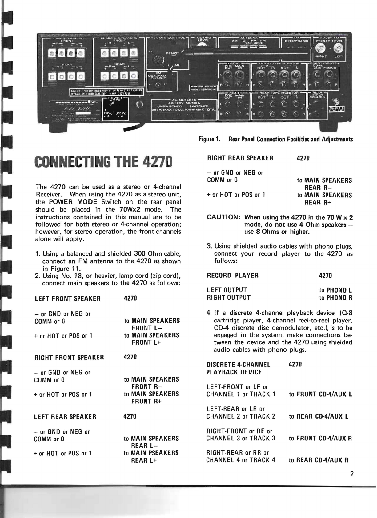
Figure
1.
Rear
Panel
Connection
Facilities
and
Adjustments
CONNECTING
The
4270
Receiver. When using
the
POWER MODE Switch on
should be placed in
can be used as a stereo or 4-channel
THE
the
4270
the
70Wx2 mode.
4270
as a stereo unit,
the
rear panel
The
instructions contained in this manual are to be
for
both
followed
however, for stereo operation,
stereo or 4-channel operation;
the
front
channels
alone will apply.
1. Using a balanced and shielded
connect
an FM
antenna
to
the
300
Ohm cable,
4270
as shown
in Figure 11.
2. Using No. 18,
connect
LEFT
FRONT
- or
GND
or
COMM
+ or
RIGHT
- or
COMM
+ or
LEFT
or 0
HOT
FRONT
GND
or 0
HOT
REAR
or
or
or
or
heavier, lamp cord (zip cord),
main speakers
SPEAKER
NEG
or
POS
or 1
SPEAKER
NEG
or
POS
or 1
SPEAKER
to
the
4270
4270
to MAIN
FRONT
to MAIN
FRONT
4270
to MAIN
FRONT
to MAIN
FRONT
4270
as follows:
SPEAKERS
L-
SPEAKERS
L+
SPEAKERS
R-
SPEAKERS
R+
RIGHT
- or
COMM
+ or
CAUTION: When using
REAR
GND
or 0
HOT
or
or
NEG
POS
mode,
SPEAKER
or
or 1
do
4270
to MAIN
REAR
to MAIN
REAR
the
4270
in
the
not
use 4 Ohm speakers -
SPEAKERS
R-
SPEAKERS
R+
70 W x 2
use 8 Ohms or higher.
3. Using shielded
connect
your
audio
cables with
record player
to
phono
the
4270
follows:
RECORD
LEFT
RIGHT
PLAYER
OUTPUT
OUTPUT
4270
to
PHONO
PHONO
to
4. If a discrete 4-channel playback device
cartridge player, 4-channel reel-to-reel player,
CD-4 discrete disc demodulator, etc.), is to be
engaged in
tween
audio
DISCRETE
PLAYBACK
LEFT-FRONT
CHANNEL
LEFT
·REAR
CHANNEL
the
the
device and
cables with
4·CHANNEL
DEVICE
or LF or
1 or
TRACK
or
LR
or
2 or
TRACK
system, make connections be-
the
4270
using shielded
phono
plugs.
4270
1
to
2 to
FRONT
REAR
CD·4/AUX
CD-4/AUX
plugs,
as
L
R
(0-8
L
L
- or
GND
COMM
+ or
HOT
or 0
or
or
NEG
POS
or
or 1
to MAIN
REAR
to MAIN
REAR
SPEAKERS
L-
PSEAKERS
L+
RIGHT-FRONT
CHANNEL
RIGHT-REAR
CHANNEL
3 or
4 or
or
RF
TRACK
or
RR
TRACK
or
or
3
4
to
FRONT CD·4/AUX R
to
REAR
CD-4/AUX
R
2
I
5. Using shielded audio cables with
connect a discrete 4-channel
the
4270
as follows:
tape
phono
recorder
plugs,
to
LEFT
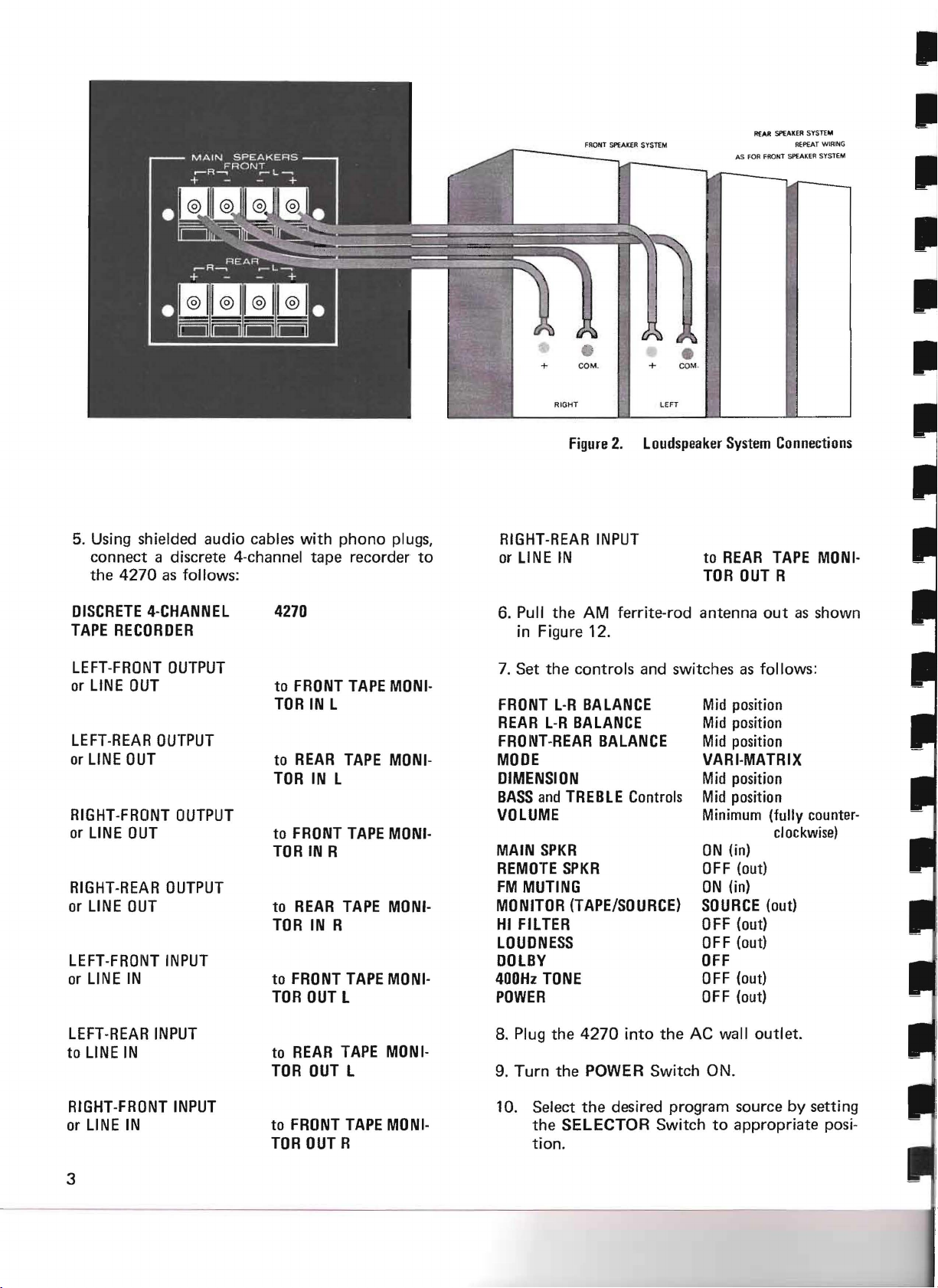
Figure
2.
Loudspeaker
RIGHT-REAR
or LINE IN to
INPUT
TOR
REAR
SPEAKER
SySTEM
AS FOR FRONT sPEAKER SYSTEM
System
REAR
OUT
R{PEAT
Connections
TAPE
R
WIRIN
G
MONI-
II
II
DISCRETE
TAPE
LEFT-FRONT
or LINE
LEFT-REAR
or
LINE
RIGHT-FRONT
or
LINE
RIGHT-REAR
or
LINE
LEFT-FROIH
or LINE IN
LEFT-REAR
to
LINE
4-CHANNEL
RECORDER
OUT
OUTPUT
OUT
OUT
OUT
INPUT
IN
OUTPUT
OUTPUT
OUTPUT
INPUT
4270
to
FRONT
TOR
to
REAR
TOR
to
FRONT
TOR
to
REAR
TOR
to
FRONT
TOR
REAR
to
TOR
IN L
IN L
IN R
IN R
OUT
OUT
TAPE
TAPE
TAPE
TAPE
TAPE
L
TAPE
L
MONI-
MONI-
MONI·
MONI-
MONI-
MONI-
6. Pull
the
in Figure 12.
Set
the
7.
FRONT
REAR
FROI\lT·REAR
MODE
DIMENSION
BASS
VOLUME
MAIN
REMOTE
FM
MUTING
MONITOR
HI
FILTER
LOUDNESS
DOLBY
400Hz
POWER
8. Plug
9. Turn
controls and switches as follows:
L-R
L-R
BALANCE
and
TREBLE
SPKR
SPKR
(TAPE/SOURCE)
TONE
the
the
AM ferrite-rod antenna
position
BALANCE
BALANCE
Controls
Mid
Mid
position
Mid
position
VARI·MATRIX
position
Mid
Mid
position
Minimum
ON
(in)
OFF
(out)
ON
(in)
SOURCE
OFF
(out)
OFF
(out)
OFF
OFF
(out)
OFF
(out)
4270
into
the
AC wall outlet.
POWER Switch ON.
out
as shown
(fully
counter-
clockwise)
(out)
RIGHT-FRONT
or
LINE
IN to
3
INPUT
FRONT
TOR
OUT
TAPE
R
MONI-
10. Select
the
SELECTOR Switch
tion.
the
desired program source by setting
to
appropriate posi-
11. If
12. Increase
Your
operative, and
ous controls to discover
The remainder
your
SOURCE DEVICES
2-channel
A stereo record player may be
PHONO jacks.
High level 2-channel playback devices (tuner,
tape
level
FRONT TAPE MONITOR and CD·4/AUX INPUTS.
phono
If FM is selected,
able listening level.
complete
system most effectively.
player, record player with equalized high
output,
is selected,
the
VOLUME control to a comfort-
4-channel
you
may
of
this manual explains
etc.) may be connected
put
on a stereo record.
tune
to
a stereo broadcast.
or
stereo system is
experiment
their
effects.
connected
with
how
the
to
to
now
vari-
to
use
the
the
4-channel
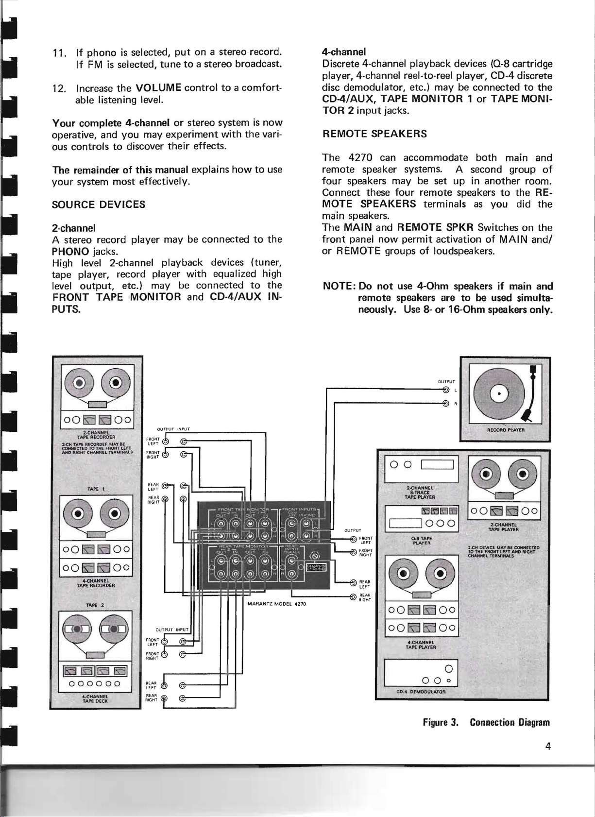
Discrete 4-channel playback devices (0-8 cartridge
player, 4-channel reel-to-reel player, CD-4 discrete
disc demodulator, etc.) may be connected to
CD-4/AUX, TAPE MONITOR 1 or TAPE MONI-
input
TOR 2
REMOTE SPEAKERS
The
4270
remote speaker systems. A second group of
four
speakers may be set up in
Connect these
MOTE SPEAKERS terminals as you did
main speakers.
The
MAIN
front
panel now permit activation of MAIN
or REMOTE groups of loudspeakers.
NOTE: Do
jacks.
can
accommodate
four
remote speakers
and
REMOTE SPKR Switches on
not
use
4-0hm
remote
neously. Use 8- or
speakers are
both main and
another
to
speakers if main
to
be used simulta-
16-0hm
speakers only.
room.
the
the
RE-
the
the
and/
and
~
00
IS:]
lS5
00
2·CHANNEL
TAPE RECORDER
2·CH TAPE
RECOR.DE~
MAT8 £
Ff
~Or4
T
CONNECTED TO THE
,o\HD RIGH T CHANNEL TER M.lMAlS
TAPE t
@) ,@
~
00
1D
OO
!SJ
4·CHANNEL
TAPE RECOROER
TAPE 2
~
1l£J
lS:l11£S5
000000
4·CHANNEL
TAPE DECK
lUT
1D00
ISJOo
.
EB
I
I
I
I
I FRONT
RIGHT
REAR
I
lEFT
REAR
RIGHT
IFRONT
LEF
f RONT
RIGHT
IREAR
LEFT
REAR
RIGHT
OUTPUT
®l
RECORD PlAYER
a
2-CHANNEL
8
.TRAC~
TAPE PLAYER
0.8
PlAYER
1SJ
ISJ
4-CHANNEL
TAPE PLAYER
CO·..
DEMODULATOR
I
~~
LD
'000
TAPE
rs:300
IS:l
00
00
'I
1001SJ
IDI
2·C"1DEVICi. MAYBE
TO THE fRONT LEFT AND RIGHT
CHANNEL
?!
1S300
2·CHANNEL
TAP1:
PLAYER
TERMINAlS
CONNECTED
10
I,
FRONT
LEFT
FRONT
RIGHT
REAR
I
T
LEFT
@l
REAR
r RIGHT
~
00
00
Figure
3.
Connection
Diagram
4
 Loading...