

Page 1

IL VOSTRO CONCESSIONARIO :
YOUR DEALER:
IHR VERTRAGSHÄNDLER:
COSTRUZIONI INDUSTRIALI
Via Cristoforo Colombo, 2
Loc. CAVAZZONA
41013 Castelfranco Emilia (MO)
Tel. 059/959811 - Fax 059/959850
04/2010 REF : 648552 (IT-EN-DE)
((440000°°//336600°°)
)
MANUALE D’ USO E MANUTENZIONE
USER’S HANDBOOK
BETRIEBS-UND WARTUNGSANLEITUNG
Page 2

2
IT
EN
DE
MRT 1440-1640-1840
1
st
DATE PUBLICATION
04/2010
Catalogue information:
Date publication:
Text and illustrations herewith enclosed
may not be reproduced, not even in part
and by any means.
Because of the possible time lag beween
the introduction of technical modifications
(an on-going process the aim of which
is to offer products which are being
continually improved) and the latest up
date of the manual, we must point out,
for the sake of correctness, that the data
contained in this edition is liable to chan-
ge at any time and are therefore not
binding.
1
st
DATUM AUSGABE
04/2010
Katalog auskunft:
Datum ausgarbe:
Die Reproduktion, auch nur teilweise, die-
ses Textes und der Abbidungen ist verboten.
Aus Gründen der Korrektheit muß darauf
hingewiesen werden, daS der
Zeitunterschied zwischen in Druck
befindlicher Naufassung und technischen
Veränderungen (die für ein Angebot von
immer basseren Geräten kontinuierlich
sind) zu Unterscheden in den Angaben
dieser Auflage Fühuren kann und daß die
darin enthaltenen Angaben underbindlinch
sind und jederzeit verändert werden kön-
nen.
1a DATA DI PUBBLICAZIONE
04/2010
Informazioni catalogo:
Data di pubblicazione:
E’ vietata la riproduzione, anche parziale,
del testo e delle illustrazioni.
La differenza tra i tempi di aggiornamento
in stampa e i tempi delle modifiche tecni-
che (variando quast’ultime
continuamente, ciò al fine di offrire prodot-
ti sempre più qualificati) impongono di
dichiarare, per correttezza, che i dati
contenuti nella presente edizione sono
suscettibili di variazione in qualsiasi
momento e che quindi non sono
impegnativi.
Page 3
IT
EN
DE
3
MRT 1440-1640-1840
Page 4
4
IT
EN
DE
MRT 1440-1640-1840
MMRRTT 1144440
0
Page 5
IT
EN
DE
5
MRT 1440-1640-1840
MMRRTT 1166440
0
Page 6
6
IT
EN
DE
MRT 1440-1640-1840
MMRRTT 1188440
0
Page 7

IT
EN
DE
7
MRT 1440-1640-1840
TABLE OF CONTENTS
11 -- IINNSSTTRRUUCCTTIIOONNS
S
- Original replacement parts and
attachments.
- Driver’s operating instructions.
- Warning
- General instructions.
- Operating instructions.
- Handling instructions.
- Load handling.
- Maintenance instructions of the lift
truck.
- Before starting up a new lift truck.
22 -- DDEESSCCRRIIPPTTIIOON
N
- Characteristics.
- Dimensions and load charts.
- Instruments and controls.
33 -- MMAAIINNTTEENNAANNCCE
E
- Filters cartridges and belts.
- Lubricants.
- Servicing schedule.
A - Daily or every 10 hours service.
B - Every 50 hours service.
C - Every 250 hours service.
D - Every 500 hours service.
E - Every 1000 hours service.
F - Every 2000 hours service.
G - Every 5000 hours service.
H - Occasional maintenance.
44 -- SSYYSSTTEEMMS
S
- Electrical system.
- Key to electrical system.
- Electrical system tables.
- Hydraulic system.
- Key to movement hydraulic system.
- Key to brake/steering hydraulic
system.
- Key to transmission hydraulic
system.
- Maintenance handbook
INHALTSVERZEICHNIS
11 -- AANNWWEEIISSUUNNGGEEN
N
- Ersatzteile und originalausstattung.
- Gebrauchsanweisung für den
fahrer.
- Warnung.
- Allgemeine anweisungen.
- Fahranweisungen.
- Handhabungsanweisungen.
- Handhabung einer last.
- Wartungsanweisungen des
gebelstaplers.
- Vor der inbetriebnahme eines neuen
gabelstaplers.
22 -- BBEESSCCHHRREEIIBBUUNNG
G
- Technische daten.
- Abmessungen und lastdiagramm.
- Steuer- und bedienungsinstrumente.
33 -- WWAARRTTUUNNG
G
- Filterelemente und riemen.
- Schmiermittel.
- Wartungsintervalle.
A -Täglich oder alle 10 Betriebsstunden.
B - Alle 50 Betriebsstunden.
C - Alle 250 Betriebsstunden.
D - Alle 500 Betriebsstunden.
E - Alle 1000 Betriebsstunden.
F - Alle 2000 Betriebsstunden.
G - Alle 5000 Betriebsstunden.
H - Gelegentliche wartung.
44 -- AANNLLAAGGEEN
N
- Elektrische Anlage.
- Legende verbraucher der
elektrischen anlage.
- Tafel der elektrischen anlage.
- Hydraulische Anlage.
- Legende Hydraulikanlage der
bewegungsabläufe.
- Legende hydraulikanlage
bremse/lenkung.
- Legende hydraulikanlage- Antrieb.
- Wartungshandbuch
INDICE
11 -- IISSTTRRUUZZIIOONNI
I
- Ricambi e attrezzature originali.
- Istruzioni d’uso per il carrellista.
- Avvertenze.
- Istruzioni generali.
- Istruzioni di guida.
- Istruzioni di movimentazione.
- Movimentazione di un carico.
- Istruzioni di manutenzione del
carrello elevatore.
- Prima della messa in marcia del
carrello elevatore nuovo.
22 -- DDEESSCCRRIIZZIIOONNE
E
- Caratteristiche.
- Dimensioni e diagramma di
carico.
- Strumenti di controllo e di
comando.
33 -- MMAANNUUTTEENNZZIIOONNE
E
- Elementi filtranti e cinghie.
- Lubrificanti.
- Periodicità’ di manutenzione.
A - Tutti i giorni o ogni 10 ore di marcia.
B - Ogni 50 ore di marcia.
C - Ogni 250 ore di marcia.
D - Ogni 500 ore di marcia.
E - Ogni 1000 ore di marcia.
F - Ogni 2000 ore di marcia.
G - Ogni 5000 ore di marcia.
H - Manutenzione occasionale.
44 -- IIMMPPIIAANNTTI
I
- Impianto elettrico.
- Leggenda impianto elettrico.
- Tavole impianto elettrico.
- Impianto idraulico.
- Schema impianto idraulico dei
movimenti.
- Schema impianto idraulico sterzo e
freni.
- Schema impianto trasmissione
idrostatica.
- Libretto manutenzione
Page 8

8
IT
EN
DE
MRT 1440-1640-1840
55 -- AADDAAPPTTAABBLLEE AATTTTAACCHH-
-
MMEENNTTSS IINN OOPPTTIIOONN OONN
TTHHEE RRAANNGGE
E
- Introduction.
- General recommendations for use of
a lift truck.
- How to mount the accessory with
manual lock
- How to mount the accessory with
hydraulic lock(optional).
- Technical specifications and load
charts of attachments.
55 -- AALLSS SSOONNDDEERRAAUUSSSSTTAATT-
-
--TTUUNNGG AANNZZUUPPAASSSSEEN
N
DDEESS ZZUUBBEEHHÖÖR
R
- Einleitung.
- Allgemeine hinweise zur verwen
dung eines gebelstaplers.
- Montage des zubehÖrtells mit manueller
verriegelung
- Montage des zubehÖrtells mit hydrauli
scherverriegelung
- Technische daten und tabelle der
tragfähigkeiten des zubehörs.
55 -- AACCCCEESSSSOORRII AADDAATTTTAABBIILLII
IINN OOPPZZIIOONNEE SSUULLLLAA
GGAAMMMMA
A
- Introduzione.
- Consigli relativi all’utilizzo del
carrello.
- Montaggio dell’accessorio con
bloccaggio manuale.
- Montaggio dell’accessorio con
bloccaggio idraulico (opzional).
- Caratteristiche tecniche accessori e
diagrammi di portata.
Page 9
IT
EN
DE
9
MRT 1440-1640-1840
INTRODUCTION
Our telescopic lift rotativ trucks have
been designed to ensure simple
manoeuvres and easy maintenance.
Before operating the truck for the first
time, the driver should read and become
fully familiar with the various chapters in
this manual.
These instructions have been prepared
to provide all the information required for
proper servicing and truck operation. By
complying with these instructions, the
truck driver will be able to get the best
performances from his vehicle.
The terms “right” and “left”, “front” and
“rear” used in this manual refer to positions viewed by the driver seated normally in the driving seat.
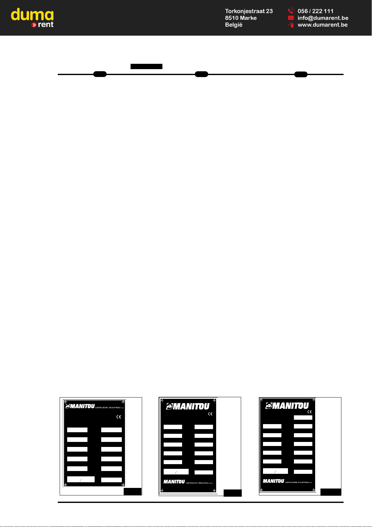
Always state the following information
when ordering spare parts or requesting
technical information:
Manufacturer's data plate (FIG.A)
-Model___________________________
-Series__________________________
- Serial N°________________________
- Chassis N°______________________
- Year of manufacture_______________
On internal combustion engine(FIG.B)
- Engine No_______________________
EINFÜHRUNG
Unsere Teleskoplader sind zu dem einzigen Zweck entwickelt worden, dem
Fahrer eine große
Bedienungsfreundlichkeit und dem
Mechaniker ein Höchstmaß an
Wartungsfreundlichkeit zu bieten.
Bevor man jedoch den Teleskoplader
zum ersten Mal in Betrieb nimmt, sollte
der Bediener die in diesem Handbuch
behandelten Argumente aufmerksam
durchlesen und verstehen, denn diese
Betriebsanleitung wurde verfaßt, um
jedes Problem zu lösen, das bei Fahren
oder der Wartung des Teleskopladers
auftauchen kann. Wenn er diese
Anleitungen befolgt, ist der Bediener in
der Lage, die Leistungsmöglichkeiten
seines Teleskopladers aufs Beste
auszunutzen. Die Begriffe “rechts” und
“links”, “vorn” und “hinten” beziehen sich
auf eine Person, die auf dem
Fahrerplatz sitzt und nach vorne schaut.
Wenn Ersatzteile bestellt werden oder
Informationen technischer Art angefordert werden, sind immer die folgenden
Angaben anzuführen:
Typenschild des herstellerrs
(ABB. A)
- Modell__________________________
- Serie___________________________
- Serien-Nr._______________________
- Fahrgestell-Nr.___________________
- Baujahr_________________________
Auf dem dieselmotor (ABB. B)
- Motor-Nr.________________________
INTRODUZIONE
I nostri carrelli elevatori telescopici rotativi sono stati progettati con l’unico
scopo di offrire all’operatore una grande
semplicità di manovra e al meccanico la
massima facilità di manutenzione.
Tuttavia, prima di mettere in funzione il
carrello elevatore per la prima volta,
l’operatore deve leggere con attenzione
e capire i vari argomenti trattati in questo manuale che è stato appunto preparato per aiutare a risolvere qualunque
problema di conduzione e di manutenzione. Seguendo queste istruzioni,
l’operatore sarà in grado di sfruttare al
meglio le potenzialità del suo carrello
elevatore telescopico.
I riferimenti di “destra” e “sinistra”,
“avanti” e “indietro” si intendono per una
persona che occupa il posto del conduttore del carrello e che guarda di fronte a
se.
Quando si ordinano i pezzi di ricambio o
per tutte le informazioni di carattere tec-
nico, si prega di specificare sempre:
Targhetta del costruttore (FIG.A)
-Modello_________________________
-Serie ___________________________
-N° d iserie_______________________
-N° di telaio______________________
- Anno di fabbricazione______________
Sul motore termico (FIG.B)
- N° del motore____________________
COSTRUZIONI INDUSTRIALI
s.r.l.
Anno di fabbricazione
(sul gancio di traino)
Carico max. verticale
SERIE
Forza di traino
MODELLO
Numero della serie
Numero del telaio
Massa a vuoto
Potenza ISO/TR14396
Pressione dei pneumatici (Bar)
VIA C. COLOMBO, 2 Loc. Cavazzona
41013 Castelfranco E. (MO) ITALY
Tel. 059 959811 - Fax 059 959850
kg
daN
Anteriore Posteriore
daN
kW
N° 726135
MANITOU BF 44158 ANCENIS CEDEX FRANCE
kg
daN
daN
kW
daN
COSTRUZIONI INDUSTRIALI
s.r.l.
MANUFACTURED BY:
Year of manufacture
(on trailer hook)
Vertical max. effort.
SERIES
Tractive effort
MODEL
Serial Nr
Chassis Nr
Unladen weight
Power ISO/TR14396
Tyre pressures (Bar)
Front Rear
Max train weight
VIA C. COLOMBO, 2 Loc. Cavazzona - 41013 Castelfranco E. (MO) ITALY
Tel. 059 959811 - Fax 059 959850
N° 726139
kg
daN
daN
kW
daN
COSTRUZIONI INDUSTRIALI
s.r.l.
MANITOU BF 44158 ANCENIS
CEDEX FRANCE
HERGESTELLT BEI:
Baujahr
(am Schlepphaken)
Maximale Zugkraft
SERIE
Zugkraft
Zul. Achslast hinten
Zul. Achslast vorn
Zul. Gesamtgew
TYP
Seriennummer
Fz Ident. Nr.
Tragkraft
Leistung nacht
ISO/TR14396
Reifendruck
(Bar)
Vorn Hinten
daN
daN
VIA C. COLOMBO, 2 Loc. Cavazzona - 41013 Castelfranco E. (MO) ITALY
Tel. 059 959811 - Fax 059 959850
N° 726141
ABB.A
FIG.A
FIG.A
Page 10
10
IT
EN
DE
MRT 1440-1640-1840
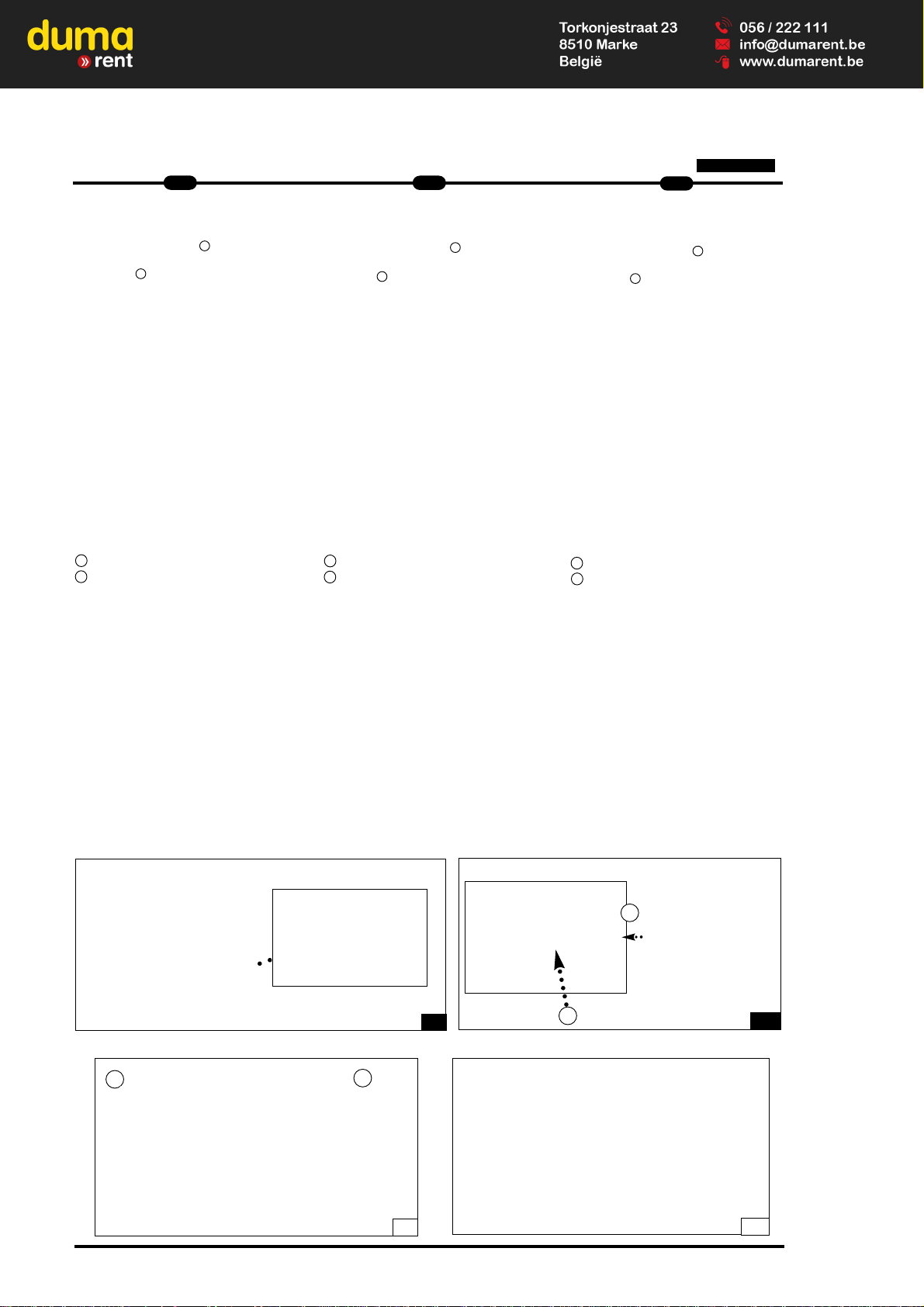
Auf dem hydrostatishen antrieb
(ABB. C)
- Bezugs-Nr. MANITOU 3___________
- Serien-Nr. 4_____________________
Auf der vorder- und hinterache
(ABB. D)
- Typ und Modell der Achse__________
________________________________
- Serien-Nr. der Vorderachse_________
________________________________
- Serien-Nr. der Hinterachse__________
_____________________________________
1 - Typ und Modell der Achse
2 - Serien-Nr.
In der kabine (ABB. E)
Kabinen-Nr.___________________
Um diese Angaben stets bei der Hand
zu haben, ist es ratsam, die Nummern
Ihres Geräts in den freien Feldern einzutragen. Da die MANITOU-Politik nach
der ständiger Verbesserung unserer
Produkte strebt, kann die Lieferpalette
unserer Teleskoplader einigen Änderungen ausgesetzt werden, deren
Bekanntgabe an die Kundschaft nicht
verpflichtend ist.
On hydrostatic drive (FIG.C)
- MANITOU referenceN° 3____________
- Serial N° 4______________________
On front and rear axle (FIG.D)
- Axle type and model_______________
________________________________
- Serial N° of front axle______________
________________________________
- Serial N° of rear axle______________
_________________________
1 - Axle type and model
2 - Serial N°
On cab (FIG.E)
Cab N°
______________________
Write all these numbers in the empty
spaces. Since the MANITOU policy is to
constantly improve our products, our
range of telescopic lift trucks may be
subject to modifications without our
being obliged to give advance warning
to our customers.
Sulla trasmissione idrostatica (FIG.C)
- N° di riferimento MANITOU 3____________
- N° di serie 4_______________________
Sull’assale anteriore e posteriore
(FIG.D)
- Tipo e modello assale__________________
____________________________________
- N° di serie dell'assale anteriore__________
____________________________________
- N° di serie dell'assale posteriore__________
____________________________________
1 - Tipo e modello dell’assale
2 - Numero di serie
Sulla cabina (FIG.E)
N° della cabina____________________
Per poter indicare più facilmente tutti
questi numeri, consigliamo di riportarli
subito negli spazi vuoti che precedono.
Poiché la politica MANITOU è di tendere
ad un miglioramento costante dei nostri
prodotti, la nostra gamma di carrelli elevatori telescopici può essere soggetta
ad alcune modifiche senza che sussista
l’obbligo per noi di dar avviso alla nostra
clientela.
1
2
D
C
E
3
4
B
Page 11

1
1
--IIS
S
T
T
R
R
U
U
Z
ZII
O
O
N
NII
IIN
N
S
S
T
T
R
R
U
U
C
C
T
TII
O
O
N
N
S
S
A
A
N
N
W
W
E
EII
S
S
U
U
N
N
G
G
E
E
N
N
Page 12

Page 13

IT
EN
DE
1
1
MRT 1440-1640-1840
ORIGINAL REPLACEMENT PARTS
AND ATTACHMENTS
All maintenance on our lift trucks
must be carried out using original
parts.
By allowing non-original parts to be
used, you run the risk:
- Legally, of being liable in the event of
an accident.
- Technically, of causing breakdowns to
occur or of reducing your lift truck's
service life.
Using counterfeit parts or components
not approved by the manufacturer may
put an end to contract warranty terms
and lead the maker to withdraw the lift
truck's certificate of compliance.
By using original parts during
maintenance operations,
you are
legally covering yourself.
- Any user who procures parts from
another quarter does so at his own
risk.
- Any user who modifies his lift truck or
has it modified by a service company,
must consider that a new item of
equipment has been brought onto the
market and therefore takes liability for
it.
- Any user who copies original parts or
has them copied is taking a risk from
the legal viewpoint.
- The certificate of compliance only
binds
the maker for parts chosen or
produced
under the maker's control.
- The practicalities of maintenance terms
are set out by the maker. The maker is
in no way liable in the event of the
user not
complying with such terms.
The manufacturer brings to the
user:
- His know-how and skill.
- Guaranteed quality work.
- Original replacement parts.
- Help with preventive maintenance.
- Effective help with diagnosing faults.
ERSATZTEILE UND ZUBEHÖR
Zur Instandhaltung unsere
Teleskoplader müssen
Originalersatzteile verwendet wer-
den
Die Verwendung nicht orginaler
Ersatzteile beinhaltet gewisse
Risiken
- Im Falle eines Unfalls die rechtlichen
Konsequenzen zu tragen
- Technische Betriebsstörungen
hervorzurufen oder die Lebensdauer
des Gabelstaplers zu verringern.
Die verwendung nicht orginaler
Ersatzteile Teilen oder vom Hersteller
nicht zugelassenen Komponenten führt
zum Erlöschen der vertraglichen
Garantie führen und zwingd den
Hersteller zum Rückzug der
Konformitätserklärung zwingen.
Durch den einsatz von originalteilenbei Instandhaltungsarbeiten,
schützen sie sich rechtlich.
- Der Benutzer, der seine Ersatzteile
anderswo bezieht, tut dies auf eigene
Gefahr
- Der Benutzer, der seinen
Teleskoplader verändert oder durch
einen Dienstleistungsbetrieb verändern
läßt, muß davon ausgehen, daß ein
neues Produkt auf den Markt kommt
und wird somit haftpflichtig.
- Der Benutzer, der Originalteile kopiert
oder kopieren läßt, setzt sich rechtlichen Gefahren aus.
- Die Konformitätserklärung bindet den
Hersteller nur für die von ihm gewählten oder unter seiner Aufsicht agefertigten Ersatzteile Teile.
- Die praktischen Wartungsbedingungen
werden vom Hersteller definiert. Sollte
der Benutzer diese nicht einhalten,
übernimmt der Hersteller keine
Haftung.
Der Hersteller bietet dem Benutzer:
- Sein Know-how und seine Kompetenz.
- Eine Qualitätsgarantie der
durchgeführten Arbeiten.
- Original Ersatzteile.
- Hilfestellungen zur vorbeugenden
Wartung.
- Eine wirkungsvolle Diagnosehilfe.
RICAMBI E ATTREZZATURE ORIGINALI
La manutenzione dei nostri carrelli
elevatori deve tassativamente esse-
re realizzata con pezzi originali.
Autorizzando l’utilizzo di pezzi non
originali, rischiate:
- Giuridicamente di coinvolgere la
vostra responsabilità in caso
d’incidente.
- Tecnicamente di causare problemi di
funzionamento alla longevità del
carrello elevatore.
L’utilizzo - da parte dell’utente - di pezzi
contraffatti o di componenti non omolo-
gati può mettere un termine alle condi-
zioni di garanzia contrattuale e indurre il
costruttore al ritiro del Certificato di
Conformità.
Utilizzando i pezzi originali durante
le operazioni di manutenzione, vi
proteggete giuridicamente.
- L’utente che si rifornisce altrove, lo fa a
suo rischio e pericolo.
- L’utente che modifica o fa modificare
da terzi il carrello elevatore, deve
essere consapevole che un nuovo
materiale è messo sul mercato, il che
coinvolge la sua responsabilità.
- L’utente che copia o fa copiare i pezzi
d’origine, si espone a rischi giuridici.
- Il Certificato di Conformità implica la
responsabilità del fabbricante solo per i
pezzi scelti o elaborati sotto il suo controllo.
- Le condizioni pratiche di manutenzione
sono fissate dal fabbricante. Se
l’utente non le rispetta, la responsabilità del fabbricante non è coinvolta.
Il fabbricante apporta all’utente:
- Il savoir-faire e la sua competenza.
- La garanzia della qualità dei lavori
realizzati.
- I pezzi di ricambio originali.
- Un’assistenza alla manutenzione
preventiva.
- Un’efficace assistenza alla diagnosi.
Page 14

2
1
IT
- Enhancements gained from feedback.
- Training for operating staff.
- Only the manufacturer knows the
details of the lift truck design and the
refore has the best technological capa
bility to carry out maintenance.
Original replacement parts are
distributed exclusively
by MANITOU and its dealer
network.
You can obtain the list of dealers by
phoning the spare parts department on :
TEL : 0033240091011
- Ständige Weiterentwicklung der
Produkte.
- Eine Ausbildung des
Betriebspersonals.
- Nur der Hersteller kennt die
Konstruktion
des Teleskopladers im Detail und
verfügt somit über die besten techni
schen Fähigkeiten, um dessen
Wartung zu gewährleisten.
Originalersatzteile werden aussch-
ließlich von MANITOU und dem
netz seiner Vertragshändler
vertrieben.
Ein Anruf bei unserer Ersatzteilabteilung
genügt und Sie erhalten die Liste der
Vertragshändler :
TEL : 0033240091011
EN
DE
MRT 1440-1640-1840
- I miglioramenti dovuti allo scambio di
esperienze.
- La formazione del personale
incaricato.
- Solo il fabbricante conosce
dettagliatamente la progettazione del
carrello e quindi le migliori capacità
tecnologiche per assicurarne la
manutenzione.
I pezzi di ricambio d’origine sono
distribuiti esclusivamente da
MANITOU
e dalla rete dei concessionari.
La lista della rete dei concessionari può
esservi fornita telefonando al servizio
dei pezzi di ricambio :
TEL : 059950518
Page 15

DRIVER’S OPERATING INSTRUCTION
Caution
Whenever you see this symbol it
means :
Warning! Be careful! Your safety or
the safety of the lift truck is at risk.
- Most accidents connected with the
use, maintenance and repair of the lift
truck are due to non application of the
basic safety instructions. By being
aware of the risks to which you are
exposed and by taking the necessary
preventive measures, you should be
able to avoid accidents occurring.
- Any operation or manoeuvre not
described in the instructions is prohibited, however, any person who does
use another method must first ensure
that he is not putting himself, another
person or the lift truck in danger.
- The manufacturer is not able to anticipate all possible risk situations.
Therefore the safety instructions and
notices given in the user manual and
on the lift truck are not exhaustive.
Any bending of the rules in safety noti-
ces or the user, maintenance or repair
instructions for your lift truck may result
in serious, or even fatal, accidents.
We would remind users of the risks in
driving at excessive speed with regard
to traffic conditions, particularly :
- Risk of loss of control on a poor-qua
lity track.
- Increased stopping distance.
BEDIENUNGSANLEITUNG FÜR
DEN FAHRER
Warnung
Dieses Symbol bedeutet:
Achtung! Seien Sie vorsichtig! Ihre
Sicherheit, die Sicherheit Dritter
oder die des Teleskopladers sind in
Gefahr.
- Die meisten Unfälle beim Gebrauch,
bei der Wartung und bei der Reparatur
des Gabelstaplers sind auf die
Nichtanwendung und Nichteinhaltung
der grundlegenden
Sicherheitsanweisungen zurückzuführen. Wenn Sie diese Gefahren erkennen, und die nötigen vorbeugenden
Maßnahmen treffen, können Sie diese
Unfälle vermeiden.
- Jegliche Anwendung, jedes Manöver,
welches in den Bedienungsanleitung
nicht beschrieben sind, sind von vorn
zu unterlassen.
- Der Hersteller haftet auf keinen Fall für
alle Gefahrensituationen. Die
Anweisungen und
Sicherheitsvorschriften in diesem
Handbuch und auf dem Teleskoplader
selbst erheben daher keinen Anspruch
auf Vollständigkeit.
Alle Verstöße gegen die
Sicherheitsvorschriften, Bedienungs-,
Wartungs- oder Reparaturanweisungen
Ihres Gabelstaplers können schwere, ja
sogar tödliche Unfälle verursachen.
Beachten Sie die Gefahren, welche
durch nicht angepasste
Geschwindigkeit, den
Verkehrsbedingungen,
Witterungsbedingungen und
Fahrbahnbeschaffenheit entstehen:
-Es besteht die Gefahr, in Abhängigkeit
von Geschwindigkeit, Witterung und
Fahrbahnbeschaffenheit die Kontrolle
uber das Fahrzeug zu verlieren
-Der Bremsweg kann sich erheblich
verlängern.
IT
EN
DE
1
3
MRT 1440-1640-1840
ISTRUZIONI D’USO PER
IL CARRELLISTA
Avvertenza
Ricordate che questo simbolo
significa:
Attenzione! Prudenza! Sono in
gioco la vostra sicurezza e quella
del carrello elevatore.
- La maggior parte degli incidenti legati
all’utilizzo, alla manutenzione e alla
riparazione del carrello elevatore, sono
dovuti alla non-applicazione e all’inosservanza delle più elementari norme di
sicurezza. Individuando i rischi ai quali
vi esponete e prendendo tutte le
necessarie precauzioni, potrete evitare
questi incidenti.
- Tutte le operazioni o manovre non
descritte nel manuale d’istruzioni devono essere evitate, e in ogni caso colui
che utilizza un altro metodo deve
prima assicurarsi che sia garantita la
propria incolumità, quella degli altri e il
buono stato del carrello elevatore.
- Pertanto, non potendo prevedere tutte
le situazioni di pericolo, le istruzioni e
norme di sicurezza relative al carrello
elevatore, date dal costruttore e riportate nel presente manuale, non sono
da considerarsi esaustive.
L’inosservanza delle norme di sicurezza
o delle istruzioni d’uso, di manutenzione
o di riparazione del carrello elevatore
possono essere all’origine di gravi infor-
tuni, anche mortali.
Richiamiamo l’attenzione degli utilizzato-
ri sui rischi a cui vanno incontro, andan-
do ad una velocità eccessiva rispetto
alle condizioni di circolazione, in
particolare:
- Rischio di perdere il controllo su stra
da dissestata.
- Aumento dello spazio di frenata.
Page 16

4
1
IT
The user must remain in full control of
his lift truck and should :
- Adapt his speed to each situation in
order to be maintain his own safety,
that of others and of his equipment.
- Always be aware of his stopping
distance.
On the basis of experience, there are a
number of possible situations in which
operating the lift truck is contra-indicated. Such foreseeable abnormal uses,
the main ones being listed below, are
strictly forbidden.
- The foreseeable abnormal behaviour
resulting from ordinary neglect, but
does not result from any wish to put
the machinery to any improper use.
- The reflex reactions of a person in the
event of a malfunction, incident, fault,
etc. during operation of the lift truck.
- Behaviour resulting from application of
the "principle of least action" when
performing a task.
- For certain machines, the foreseeable
behaviour of such persons as :
apprentices, teenagers, handicapped
persons and trainees tempted to drive
a lift truck. Truck drivers tempted to
operate a truck to win a bet, in
competition or for their own personal
experience.
The person in charge of the equipment
must take these criteria into account
when assessing whether or not a per-
son will make a suitable driver.
- Get to know the telescopic fork lift
truck on the terrain where it is to be
used.
- Transport the load with the boom
lowered and fully retracted
- Position the forks at right-angles to the
load to be lifted.
- Drive the truck at a speed appropriate
to conditions and the state of the
ground.
- Never go too fast or brake sharply with
a load.
- When picking up a load, check that the
ground is as even as possible.
Der Benutzer muß das Fahrzeug stän-
dig unter Kontrolle haben :
- Die Geschwindigkeit der Situation
anpassen, um die eigene Sicherheit,
die Sicherheit Dritter und die des
Teleskopladers zu bewahren.
- Den Bremsweg ständig einschätzen
können.
Erfahrungsgemäß können bestimmte
Gegenanzeigen für den Einsatz des
Gabelstaplers auftreten. Diese vorherseh-
baren, unnormalen Einsätze, von denen
die hauptsächlichen nachstehend genannt
werden, sind strengstens untersagt.
-Das vorhersehbare. unnormale
Verhalten aufgrund einer gewòhnlichen
Fahrlàssigkeit. dasjedoch nicht auf
dem Willen eines falschen
Materialeinsatzes beru ht.
-Das Reflexverhalten einer Person bei
einer Funklionsstòrung. einem
Zwischenfall. einer Stòrung. usw. wàh
rend der Benutzung des Gabelstaplers.
-Das Verhalten. das auf der Anwendung
des "Wegs des geringsten
Widerstands" wàhrend der AusfOhrung
einer Arbeit beruht.
-Bei manchen Maschinen das voraus
sehbare Verhalten mancher Personen.
wie z. B.: lehrlinge. Jugendliche.
Behinderte. Praktikanten. die versucht
sind. einen Gabelstapler zu fahren.
Gabelstaplerfahrer. die versucht sind.
den Gabelstapler fOr Wetten.
Wettbewerbe oder fOr ihre eigene
Erfahrung einzusetzen.
Der verantwortliche Mitarbeiter muß
diese Kriterien bei der Bewertung der
Fahrtüchtigkeit einer Person berücksi-
chtigen.
- Machen Sie sich vor jedem Einsatz mit
dem Teleskoplader und den
Geländegegebenheiten vertraut...
- Transportieren Sie die Last in niedriger
Stellung und mit ganz eingefahrenem
Teleskoparm .
- Positionieren Sie die Gabelzinken waa
gerecht zu der anzuhebenden Last.
- Fahren Sie den Gabelstapler mit einer
den Bedingungen und dem Zustand
des Untergrunds angepaßten
Geschwindigkeit.
- Vermeiden Sie beim Fahren mit Last
zu hohe Geschwindigkeit und abrupte
Bremsmanöver.
- Vergewissern Sie sich vor dem
Aufnehmen einer Last, daßder
Untergrund ausreichen tragfähig und
eben ist
EN
DE
MRT 1440-1640-1840
L'utilizzatore deve sempre poter control-
lare il carrello elevatore e
quindi deve :
- Adattare la velocità ad ogni situazione
per preservare la propria incolumità,
quella altrui e quella della propria
macchina.
- Valutare continuamente lo spazio di
frenata.
L’esperienza ci insegna che si possono
avere alcune controindicazioni sull’im-
piego del carrello elevatore. Questi
impieghi anomali prevedibili, di cui i prin-
cipali sono elencati qui di seguito, sono
formalmente vietati.
- Il comportamento anomalo prevedibi-
le, che risulta da una negligenza ordinaria, ma che non risulta dalla volontà
di fare un cattivo uso della macchina.
- Il comportamento riflesso di una per-
sona in caso di cattivo funzionamento,
d’incidente, di anomalia, ecc. durante
l’utilizzo del carrello elevatore.
- Il comportamento risultante dall’appli-
cazione della “legge del minimo
sforzo” durante l’esecuzione di un
compito.
- Per alcune macchine, il comportamen-
to prevedibile di certe categorie di persone, quali: apprendisti, adolescenti,
portatori di handicap, personale in
formazione.
I carrellisti tentati di utilizzare il carrello
elevatore per scommesse, competizioni
o per esperienza personale.
Il responsabile dello stabilimento deve
tenere conto di questi criteri per valuta-
re l’attitudine alla guida di una persona.
- Prendere confidenza con il carrello
elevatore telescopico sul terreno dove
sarà utilizzato.
- Trasportare il carico in posizione bassa
e il braccio telescopico rientrato al
massimo .
- Posizionare le forche
perpendicolarmente al carico da
sollevare.
- Guidare il carrello ad una velocità
adeguata alle condizioni e allo stato
del terreno.
- Non andare mai troppo forte né frenare
bruscamente con un carico .
- Al momento di prendere un carico,
verificare che il terreno sia il più
uniforme possibile .
Page 17

- Never attempt to carry out operations
which exceed the lift truck’s capabili
ties.
- Never raise a load in excess of the
lift truck’s capacity and never increase
the size of the ballast.
- Drive around obstacles.
- Take care over electrical wires, tren
ches and recently-excavated or filled
ground.
- Never leave the engine running
unattended.
- Use the parking brake when depositing
difficult loads or on sloping ground.
- Never leave the truck parked with a
raised load.
- Never authorise anyone to approach
or pass below a load.
- Always think of safety and only tran
sport
well balanced loads.
- Never lift a load using one fork only.
- Drive with care and with reflexes alert.
- When the lift truck is not in use, lower
the forks to the ground and engage the
parking brake.
- Never leave the ignition key in the
truck unattended.
- Never leave the truck loaded on a
gradient of over 15% even with the
parking brake engaged.
- When lifting a load, take care that
nothing and no-one interferes with the
movement and adopt proper handling
procedures only.
- Comply with the data provided in the
load diagrams.
- Never transport another person on the
lift truck.
Whenever an implement is changed, to
prevent damage to the hydraulic unions
always proceed as follows:
- Stop the engine
- wait 1 minute for the circuit to
depressurise
Moreover check that the unions are
clean.
- Ensure that the coupling faces are
clean.
- Achten Sie auf die ordnungsgemäße
Verwendung der Steuer - und
Bedieneinrichtungen.
- Versuchen Sie keinesfalls, Arbeiten
durchzuführen, die die Tragfähigkeit
des Teleskopladers überschreiten.
- Heben Sie keinesfalls eine Last an, die
die Tragfähigkeit des Gabelstaplers
übersteigt und erhöhen Sie keinesfalls
das Ausmaß des Kontergewichtes.
- Fahren Sie um Hindernisse herum.
- Achten Sie auf
Stromkabel,Freileitungen, Gräben,
Frisch ausgehobene oder ange
schüttete Böden.
Den Motor in Abwesenheit des Fahres
abstellen.
-Benutzen Sie die Feststellbremse zum
absetzen der Last oder bei Gefälle.
- Den Teleskoplader niemals mit angeho
bener Last abstellen.
Achten Sie darauf, daß sich keine
Personen im Gefahrenbereich der
Maschine oder der Last befinden.
-Aus Sicherheitsgründen, ermitteln Sie
immer den Lastschwerpunkt der
Ladung vor dem Anheben oder dem
Transport.
-Fahren Sie immer mit angepasster
Geschwindigkeit, erhöhter
Aufmerksamkeit und der nötigen
Vorsicht.
-Nach dem Abstellen des
Teleskopladers, ziehen Sie die
Feststellbremse an und senken Sie die
Gabelzinken auf den Boden ab.
- Beachten Sie die in den
Traglastdiagrammen angegebenen
Daten.
- Transportieren Sie niemals weitere
Personen auf dem Gabelstapler.
Jedesmal wenn ein Anbaugerät
ausgewechselt werden soll, beachten
Sie folgende Punkte, um Schäden an
den Hydraulikanschlüssen zu
vermeiden:
- Lassen Sie den Druck ab, indem Sie
den
Verteilerhebel betätigen.
- Vergewissern Sie sich stets, daß diese
Anschlüsse sauber sind.
- Non tentare di compiere operazioni
che superino le capacità del carrello
elevatore.
- Non sollevare un carico superiore alla
capacità del carrello elevatore e non
aumentare la dimensione del
contrappeso.
- Girare intorno agli ostacoli.
- Fare attenzione ai cavi elettrici, ai
fossi, ai terreni scavati da poco o
riportati.
- Non lasciare mai il motore acceso in
assenza del guidatore.
- Utilizzare il freno di stazionamento per
deporre un carico difficile o su un
terreno in pendenza.
- Non lasciare in nessun caso il carrello
in parcheggio con un carico sollevato.
- Non autorizzare nessuno ad avvicinar
si o a passare sotto un carico.
- Pensare sempre alla sicurezza e
trasportare solamente dei carichi ben
equilibrati.
- Non sollevare mai un carico utilizzan
do solamente una forca.
- Guidare con prudenza e prontezza di
riflessi.
- Quando il carrello elevatore non viene
utilizzato, abbassare al suolo le forche
e inserire il freno di stazionamento.
- Non lasciare mai la chiave
d'avviamento sul carrello in assenza
del guidatore.
- Non lasciare il carrello carico su una
pendenza superiore al 15% anche con
il freno di stazionamento inserito.
- Quando si effettua il sollevamento di
un carico, fare attenzione che nulla o
nessuno intralci il movimento ed evita
re di effettuare false manovre.
- Attenersi ai dati indicati sui diagrammi
di carico.
- Non trasportare mai un’altra persona
sul carrello elevatore.
Ogni volta che si cambia un attrezzo,
per evitare di danneggiare i raccordi
idraulici occorre:
- arrestare il motore termico
- aspettare circa 1 minuto per togliere la
pressione del circuito
Inoltre controllare la pulizia di questi
raccordi.
IT
EN
DE
1
5
MRT 1440-1640-1840
Page 18

6
1
IT
GENERAL INSTRUCTIONS
A - Driver’s operating instructions.
- Read the operator's manual carefully,
making sure you understand it.
- The operator’s manual must always be
kept in the lift truck, in the place provided and in the language understood by
the operator.
- Respect the safety notices and instructions given on the lift truck.
- It is compulsory to replace all plates or
stickers which are no longer legible or
which have become worn or damaged.
B - Authorisation to operate (Or
refer to the legislation for each
particular country).
- Only qualified personnel may use the
lift truck. Its use is subject to authorisation to operate being given by the
appropriate manager in the user establishment.
- The user should always carry this
authorisation to operate with him while
he is using the lift truck.
- The driver is not competent to authori
se the driving of the lift truck by
another person.
- In addition, the vehicle should be used
in accordance with good practice for
the profession.
C - Maintenance.
- The user must immediately advise his
superior if his lift truck is not in good
working order or does not comply with
the safety notice.
- The operator is prohibited from
carrying out any repairs or adjustments
himself, unless he has been trained for
this purpose. He must keep the lift
truck properly cleaned if this is among
his responsibilities.
- Carry out daily maintenance (See
chapter : A - DAILY OR EVERY 10
HOURS SERVICE in paragraph : 3 MAINTENANCE).
- Ensure tyres are adapted to the nature
of the ground (See area of the contact
surface of the tyres in the chapter :
CHARACTERISTICS in paragraph : 2 DESCRIPTION).
ALLEGEMEINE ANWEISUNGEN
A - Bedienungsanleitung.
- Die Bedienungsanleitung sorgfältig
lesen und sicherstellen,daßdie Inhalte
und Vorgehensweisen verstanden wurden..
- Die Bedienungsanleitung muß sich
ständig an der dafür vorgesehenen
Stelle im Teleskoplader befinden und in
der vom Fahrer gesprochenen Sprache
sein.
- Die Sicherheitsvorschriften und die auf
dem Gabelstapler beschriebenen
Anweisungen beachten.
- Unbedingt alle Beschriftungen oder
Aufkleber ersetzen, welche verschlissen, unleserlich oder.
B - Fahrerlaubnis
Siehe die entsprechende
Gesetz-
gebung des jeweiligen Landes.
- Nur qualifiziertes und ausgebildetes
Personal darf den Teleskoplader benutzen. Die Benutzung unterliegt zwangsläufig den Regularien des Betreibers
oder dessen Beauftragten.
- Während der Arbeitszeit muß der
Benutzer die Fahrerlaubnis ständig bei
sich tragen.
- Der Fahrer ist nicht dazu befugt, das
Führen des Gabelstaplers durch eine
weitere Person zu erlauben.
- Desweiteren unterliegt die Benutzung
denRegeln dieses Berufszweigs.
C - Instandhaltung.
- Sollte der Benutzer feststellen, daß der
Gabelstapler sich nicht in betriebsbereitem Zustand befindet oder nicht den
Sicherheitsvorschriften entspricht, muß
er dies sofort seinem Vorgesetzten mitteilen.
- Es ist dem Fahrer untersagt, selbst
Reparaturen oder Einstellungen vorzunehmen, es sei denn er wurde hierzu
ausgebildet. Wenn ihm dies übertragen
wurde, muß er seinen Gabelstapler
selbst in einem einwandfreien
Betriebsicheren Zustand halten.
- Durchführung der täglichen
Wartungsarbeiten: (Siehe Kapitel : A TÄGLICH ODER ALLE 10 BETRIEBSSTUNDEN, Abschnitt : 3 - WARTUNG).
- Überzeugen Sie sich, daß die Reifen
für die Bodenart geeignet sind (Siehe
TECHNISCHE DATEN, Abschnitt : 2 BESCHREIBUNG).
ISTRUZIONI GENERALI
A - Manuale d’istruzione.
- Leggere con attenzione e comprendere il manuale d'istruzioni.
- Il manuale d'istruzione deve sempre
trovarsi al suo posto nel carrello elevatore ed essere nella lingua parlata dal
carrellista.
- Osservare le norme di sicurezza e le
istruzioni descritte per il carrello
elevatore.
- Sostituire imperativamente tutte le
targhette o gli adesivi diventati illeggibi
li o deteriorati.
B - Autorizzazione di guida
(Attenersi alla legislazione in
vigore nel paese d’utilizzo).
- Solo il personale qualificato ed appositamente addestrato può utilizzare il
carrello elevatore. Il suo utilizzo è
obbligatoriamente sottoposto all'autorizzazione di guida rilasciata dal
responsabile dello stabilimento dove la
macchina viene utilizzata.
- Si consiglia all'utilizzatore di avere
sempre con sé durante il servizio
l'autorizzazione di guida.
- Il conduttore non può autorizzare la
guida del carrello elevatore ad una
altra persona.
- L'utilizzo deve essere inoltre conforme
alle regole dell'arte della professione.
C - Manutenzione ordinaria.
- L'utilizzatore che constata che il suo
carrello elevatore non funziona bene o
non risponde alle norme di sicurezza,
deve informare immediatamente il
responsabile.
- È vietato al conduttore effettuare lui
stesso qualsiasi riparazione o regolazione a meno che non sia stato formato per tale compito. Dovrà tenere il suo
carrello elevatore in perfetto stato qualora ne sia stato incaricato.
- Effettuare la manutenzione giornaliera
(Vedi capitolo : A - OGNI GIORNO O
OGNI 10 ORE DI FUNZIONAMENTO
nella parte : 3 - MANUTENZIONE).
- Verificare che i pneumatici siano adeguati al tipo di terreno (Vedi superficie
di contatto al suolo dei pneumatici,
capitolo : CARATTERISTICHE nella
parte 2 - DESCRIZIONE)
EN
DE
MRT 1440-1640-1840
Page 19

THERE ARE:
• SAND tyres.
• LAND tyres.
• Snow chains.
There are optional solutions, consult
your agent or dealer.
Do not use a worn or damaged tyre
The fitting of foam inflated tyres is prohi-
bited and is not guaranteed by
the manufacturer, excepting prior
authorisation.
- For your own and other people's
safety, it is forbidden to modify the
structure and settings of the various
components of your lift truck yourself
(Hydraulic pressure, relief valve calibration, I.C. engine running speed,
addition of extra equipment etc.). The
same holds with regard to any suppression or modification of the safety
systems, in which case the maker
would no longer be liable.
Regular inspection of your lift truck is
mandatory if it is to be kept in conforming condition. The frequency of such
checks are defined by the current legi-
slation of the country in which the lift
truck
is being operated.
Maintenance or repairs other than those
detailed in part : 3 - (MAINTENANCE)
must be carried out by qualified person-
nel (Consult your agent or dealer) and
under the necessary safety conditions
to maintain the health of the operator
and any third party.
D - Environment.
- A lift truck operating in an area without
fire extinguishing equipment must be
equipped with an individual extinguisher. There are optional solutions, consult your agent or dealer.
- Take into account climatic and atmospheric conditions of the site of utilisation.
ES GIBT:
• SANDREIFEN.
• LANDWIRTSCHAFTSREIFEN.
• Schneeketten.
Es gibt Sonderausstattungen, fragen
Sie Ihren r Vertragshändler.
verschlissenen oder beschädigten Rei-
fen nicht benutzen
Das Aufziehen von mit "geschäumten
Reifen jeglicher Art ist untersagt und wird
nicht vom Hersteller gewährleistet, es sei
denn, er hat eine vorherige Freigabe
erteilt.
- Für Ihre Sicherheit und die Sicherheit
Dritter ist es untersagt, die Struktur und
die Einstellungen der verschiedenen
Komponenten des Teleskoplade selbst
zu verändern (Hydraulikdruck,
Einstellung der Begrenzungsventile,
Motordrehzahl, Hinzufügen von
Zusatzausstattungen, usw.). Das gleiche gilt für die Änderung oder
Entfernung der
Sicherheitsvorrichtungen. In solchen
Fällen ist die Haftung des Herstellers
ausgeschlossen.
Um die Konformität des Teleskopladers
zu gewährleisten, muß dieser
regelmäßig einer Untersuchung unter-
zogen werden, wobei die
Prüfungshäufigkeit von der
Gesetzgebung des jeweiligen
Einsatzlandes des Teleskopladers vor-
gegeben wird.
Die Wartung oder die Reparaturen, die
nicht in Teil : 3 - (WARTUNG) beschrie-
ben sind, müssen von qualifiziertem
Personal durchgeführt werden (wenden
Sie sich an Ihren oder
Vertragshändler). Bei allen
Wartungsarbeiten sind die entsprechen-
den Sicherheitsvorschriften und
Umweltvorschriften des jeweiligen
Einsatzlandes des Teleskoplader zu
beachten
D - Umfeld.
- Sollte der Gabelstapler in einem
Umfeld ohne Löschmittel eingesetzt
werden, muß er mit einem eigenen
Feuerlöscher ausgestattet werden. Es
gibt entsprechende
Sonderausstattungen, fragen Sie Ihren
oder Vertragshändler.
- Klimatische und atmosphärische
Bedingungen des Einsatzortes berücksichtigen
ESISTONO:
• Pneumatici da SABBIA.
• Pneumatici da TERRENO AGRICOLO.
• Catene da neve.
Esistono altre soluzioni opzionali ; per
maggiori informazioni rivolgetevi al
vostro agente o concessionario.
Non usare i pneumatici consumati o
deteriorati
Montare pneumatici gonfiati con schiu-
ma poliuretanica è vietato e non è
garantito dal costruttore, salvo autoriz-
zazione.
- Per la vostra sicurezza e quella altrui,
non modificate voi stessi la struttura o
la regolazione dei vari componenti del
carrello elevatore (Pressione idraulica,
taratura dei limitatori, regime motore,
montaggio di attrezzature supplementari, ecc.). Lo stesso vale per la disattivazione o la modifica dei sistemi di
sicurezza. In questi casi, il costruttore
sarà svincolato da ogni responsabilità.
Per mantenere il carrello elevatore in
“stato di conformità”, è obbligatorio
effettuare controlli periodici. La frequenza dei controlli è definita dalla normativa
vigente nel paese d’utilizzo del
carrello elevatore.
Le operazioni di manutenzione o le ripa-
razioni non riportate nella parte : 3 -
(MANUTENZIONE) devono essere
effettuate da personale qualificato (Per
maggiori informazioni, rivolgetevi al
vostro agente o concessionario) e
rispettando le condizioni di sicurezza
atte a garantire la vostra
incolumità e quella altrui.
D - Condizioni ambientali d’uso.
- Dotare il carrello elevatore di un estin-
tore qualora la macchina venga utilizzata in un luogo sprovvisto di mezzi
d'estinzione. Esistono soluzioni opzionali. Per maggiori informazioni, rivolgetevi al vostro agente o concessionario.
- Tenere sempre conto delle condizioni
climatiche ed atmosferiche del luogo di
utilizzo.
IT
EN
DE
1
7
MRT 1440-1640-1840
Page 20

8
1
IT
For operation under average climatic
conditions, i.e. : between -15 °C and
+ 35 °C, correct levels of lubricants in all
the circuits are checked in production.
For operation under more severe clima-
tic conditions, before starting up, it is
necessary to drain all the circuits, then
ensure correct levels of lubricants using
lubricants properly suited to the relevant
ambient temperatures. It is the same for
the cooling liquid.
• Protection against frost (See chapter :
LUBRICANTS AND FUEL in
paragraph : 3 - MAINTENANCE).
• Adaptation of lubricants (Ask your
dealer for information).
• Engine filtration.
• Lighting (Working headlight).
Optional solutions exist, consult your
dealer.
Use of a lift truck is prohibited in protected areas (e.g. refinery, explosive atmo-
sphere). For use in these areas,
specific equipment is available as an
option. Consult your dealer.
If necessary, consult your dealer.
Die Schmiermittel werden im Werk für
durchschnittliche Klimabedingungen ein-
gefüllt, d. h. -15°C bis + 35°C. Für strengere Einsätze muß der Gabelstapler vor
der Inbetriebnahme entleert und mit für
die Umgebungstemperaturen geeigne-
ten Schmiermitteln gefüllt werden. Dies
gilt auch für das Kühlmittel.
• Frostschutz (Siehe Kapitel : SCHMIERMITTEL UND KRAFTSTOFF,
Abschnitt : 3 - WARTUNG).
• Anpassung der Schmiermittel
(Erkundigen Sie sich bei Ihrem oder
Vertragshändler).
• Motorölfilter.
• Beleuchtung (Arbeitsscheinwerfer).
Es gibt Sonderausstattungen, fragen Sie
Ihren oder Vertragshändler.
Der Einsatz des Teleskopladers in EX -
geschützten Räumen ist untersagt (Z.
B. Raffinerie, explosionsgefährdete
Atmosphäre). Für einen Einsätze in sol-
chen Räumen gibt es
Sonderausstattungen. Fragen Sie Ihren
oder Vertragshändler.
Im Zweifelsfall fragen Sie Ihren
oder Vertragshändler.
Il pieno di lubrificanti è già stato effettua-
to in fabbrica, utilizzando lubrificanti per
condizioni climatiche d'uso medie, ossia
da -15°C a + 35°C. Per un utilizzo in
condizioni estreme occorre, prima del-
l'avviamento, svuotare e rifare i pieni,
utilizzando i lubrificanti adatti a tali temperature. Lo stesso vale per il liquido di
raffreddamento.
• Protezione dal gelo (Vedi capitolo :
LUBRIFICANTI E CARBURANTE nella
parte : 3 - MANUTENZIONE).
• Impiego di lubrificanti adeguati (Per
maggiori informazioni rivolgetevi al
vostro agente o Concessionario).
• Filtri motore.
• Luci (Faro di lavoro).
Esistono altre soluzioni opzionali. Per
maggiori informazioni rivolgetevi al
vostro agente o concessionario.
L'utilizzo del carrello elevatore è vietato
negli spazi protetti (Es. : Raffinerie,
atmosfera esplosiva). Per l'utilizzo in
questi spazi, esistono attrezzature
opzionali specifiche. Rivolgetevi al
vostro agente o concessionario.
In caso di necessità rivolgetevi al
vostro agente o concessionario.
EN
DE
MRT 1440-1640-1840
Page 21

OPERATING INSTRUCTIONS
A - Driver’s operating instructions.
- Wear clothes suited for driving the lift
truck, avoid loose clothes.
- Never operate the vehicle when hands
or feet are wet or soiled with greasy
substances.
- For increased comfort, adjust the driver’s seat to your requirements and
adopt the correct position in the driver’s cab.
- The operator must always be in his
normal position in the driver’s cab. It is
prohibited to have arms or legs, or
generally any part of the body, protruding from the driver’s cab of the lift
truck.
- Always remember to fasten your seat
belt and adjust it to your requirements.
- The control units must never in any
event be used for any other than their
intended purposes (e.g. climbing onto
or down from the lift truck, portmanteau, etc.).
- If the control components are fitted
with a forced operation (lever lock)
device, it is forbidden to leave the cab
without first putting these controls in
neutral.
- Never allow a passenger to travel on
the lift truck in the driver’s cab.
B - Before starting the lift truck.
- If the lift truck is new, refer to chapter :
BEFORE STARTING UP A NEW LIFT
TRUCK in paragraph : 1 - OPERATING AND SAFETY INSTRUCTIONS.
- Check the condition of the tyres and
the tyre pressures (See chapter : CHARACTERISTICS in paragraph : 2 DESCRIPTION).
- Before starting the lift truck, check the
different levels :
• Engine oil.
• Hydraulic reservoir oil.
• Transmission oil.
• Cooling liquid.
- Also check for possible leakage of oil,
fuel or liquid from the lift truck.
FAHRANWEISUNGEN
A - Sicherheithinweise.
- Zum Führen eines Gabelstaplers geeignete Kleidung tragen, weite Kleidung
vermeiden.
- Niemals mit feuchten oder fettigen
Händen oder Schuhen fahren.
- Für einen besseren Komfort, den
Fahrersitz passend einstellen und eine
sichere Sitzposition im Führerstand
annehmen.
- Es ist verboten, Arme, Beine oder,
generell, irgendein Körperteil über den
Führerstand des Teleskoplader hinausragen zu lassen.
- Immer den Sicherheitsgurt anlegen
und passend einstellen.
- Die Bedienelemente dürfen auf keinen
Fall zu einem anderen als dem
Bestimmungszweck verwendet werden
(Z. B. Auf- und Absteigen vom
Gabelstapler, Kleiderhaken, usw.).
- Sollten die Bedienelemente mit einem
System für erzwungenen Betrieb
ausgestattet sein (Hebelblockierung),
ist es verboten, den Führerstand zu
verlassen, ohne vorher diese
Steuerungen in Neutralstellung zu bringen.
- Niemals Mitfahrer auf dem
Teleskoplader und im Führerstand
zulassen.
B-Vor dem Starten des
Teleskoplader.
- Ist der Teleskoplader neu, siehe
Kapitel : VOR DER INBETRIEBNAHME EINES NEUEN
TELESKOPLADER, Abschnitt : 1 ANWEISUNGEN UND
SICHERHEITSVORSCHRIFTEN.
- Die Reifen auf ihren Zustand und den
Reifendruck prüfen (Siehe Kapitel :
TECHNISCHE DATEN, Abschnitt : 2 BESCHREIBUNG).
- Vor dem Start des Teleskoplader, die
verschiedenen Flüssigkeitsstände
überprüfen :
• Motorölstandprüfen.
• Hydraulikölstand prüfen.
•Getriebeölstand prüfen.
• Kühlmittelstand prüfen.
- Den Teleskoplader ebenfalls auf
Undichtigkeiten von Öl, Kraftstoff bzw.
Flüssigkeit überprüfen.
ISTRUZIONI PER LA GUIDA
A - Disposizioni posto guida.
- Indossare indumenti idonei alla guida
del carrello elevatore, evitando quelli
troppo larghi.
- Non guidare mai con mani o scarpe
umide o sporche di grasso.
- Per un miglior comfort, regolare il
sedile del conduttore e adottare una
buona posizione di guida.
- Il conduttore deve sempre mantenere
la posizione normale di guida. È vietato sporgere braccia e gambe e, in
generale, qualunque parte del corpo,
fuori del posto di guida del carrello elevatore.
- Allacciare e regolare sempre la cintura
di sicurezza.
- Gli organi di comando non devono mai
essere utilizzati per scopi differenti da
quelli a cui sono preposti (Es. : Salire o
scendere dal carrello elevatore, appendere indumenti, ecc.).
- Quando gli strumenti di comando sono
dotati di un dispositivo di marcia forzata (bloccaggio della leva), è vietato
lasciare il posto di comando prima di
rimettere tali comandi in folle.
- Non far salire mai passeggeri sul
carrello elevatore o nel posto di guida.
B - Prima di avviare il carrello
elevatore.
- Se il carrello elevatore è nuovo, riferirsi
al capitolo : PRIMA DI AVVIARE UN
CARRELLO ELEVATORE NUOVO
nella parte : 1 - ISTRUZIONI E
NORME DI SICUREZZA.
- Controllare lo stato e la pressione dei
pneumatici (Vedi capitolo : CARATTERISTICHE nella parte : 2 - DESCRIZIONE).
- Prima dell'avviamento verificare i vari
livelli :
• Olio motore termico.
• Olio serbatoio idraulico.
• Olio trasmissione.
• Liquido di raffreddamento.
- Controllare anche le eventuali perdite
d'olio, di combustibile o di liquido sul
carrello elevatore.
IT
EN
DE
1
9
MRT 1440-1640-1840
Page 22

10
1
MRT 1530 M
Series
- Check the closing and locking of the
hood.
- Whatever his experience as a truck driver is, the operator is advised to familiarize himself with the position and
operation of all the controls and instruments before operating the lift truck.
C - Starting the lift truck.
Safety notice.
The lift truck must only be started up or
manoeuvred when the operator is sitting
in the driver’s cab, with his seat belt
adjusted and fastened.
- Never try to start the lift truck by
pushing or towing it.
Such operation may cause severe
damage to the transmission. If neces-
sary, to tow the lift truck in an emer-
gency, the gear-box must be placed in
the neutral position (See chapter : H3 -
in paragraph : 3 - MAINTENANCE).
Instructions
- Make sure that the forward/reverse
lever is in neutral.
- Turn the ignition key to the position I to
activate the electrical system.
- Check the level on the fuel level
gauge.
- Turn the ignition key to position II to
preheat for 15 seconds. (If the
environmental conditions require it)
Do not engage the starter motor for
more than 15 seconds and carry out the
preheating for 10 seconds between
unsuccessful attempts.
- Press the accelerator pedal and turn
the ignition key fully : the I.C. engine
should then start. Release the ignition
key and let the I.C. engine run at idle.
- Before operating in very cold environ
ments wait for the I.C. engine and
hydraulic systems to heat up
adequately.
- Vergewissern Sie sich, daß alle
Zugangsklappen verschlossen und ver
riegelt sind
- Machen Sie sich mit dem
Teleskoplader,der Lage und Funktion
der Bedien- und Steuerelementen vor
Fahrtantritt vertraut.
C - Starten des Teleskoplader.
Sicherheitsvorschriften.
Der Teleskoplader darf erst gestartet
oder bedient werden, wenn der Fahrer
im Führerstand sitzt und den
Sicherheitsgurt eingestellt und angelegt
hat.
- Den Teleskoplader zum Starten nicht
ziehen oder schieben.
Eine solche Bedienung würde schwere
Beschädigungen am Übersetzungsge-
triebe hervorrufen. Sollte das
Abschleppen des Teleskopladers erfor-
derlich sein: (Siehe Kapitel :
H3 -Abschnitt : 3 - WARTUNG).
Anweisungen
- Überzeugen Sie sich davon, daß sich
der Fahrtrichtungswahlschalter in der
Neutralstellung befindet.
- Den Zündschlüssel in Stellung I
drehen, um den elektrischen Kontakt
herzustellen.
- Den Kraftstoffstand auf der Anzeige
überprüfen.
- Den Zündschlüssel in Stellung II
drehen, um ein Vorwärmen von 15
Sekunden zu ermöglichen.
(Wenn die Umgebungsbedingungen es
verlangen)
Den Anlasser nicht länger als 15
Sekunden betätigen, und zwischen
allen erfolglosen Startversuchen ein
Vorwärmen während 10 Sekunden dur-
chführen.
- Das Gaspedal niederdrücken und den
Zündschlüssel bis zum Anschlag
drehen, der Motor muß nun anspringen. Den Zündschlüssel wieder loslassen und den Motor im Leerlauf drehen
lassen.
- Bevor man unter sehr kalten
Klimaverhältnisse arbeitet, abwarten,
dass der Motor und die hydraulischen
Anlagen richtig warm geworden sind.
.
- Accertarsi della corretta chiusura e del
bloccaggio del cofano motore.
- L’utilizzatore, qualunque sia il suo
grado di esperienza come carrellista,
dovrà familiarizzarsi con la posizione e
l'utilizzo di tutti gli strumenti di controllo
e di comando, prima di mettere il carrello elevatore in servizio.
C - Avviamento del carrello
elevatore.
Norme di sicurezza.
Il carrello elevatore può essere avviato
o manovrato solo quando il conduttore
si trova al posto di guida, con la cintura
di sicurezza allacciata e regolata.
- Non trainare o spingere il carrello
elevatore per avviarlo.
Tale manovra potrebbe provocare gravi
deterioramenti alla trasmissione.
Qualora fosse necessario trainare il car-
rello elevatore, mettere il cambio in
posizione neutra(Vedi capitolo : H3 -
nella parte : 3 - MANUTENZIONE).
Istruzioni
- Verificare che la leva dell'invertitore di
marcia sia in folle.
- Ruotare la chiave di avviamento in
posizione I per consentire il contatto
elettrico.
- Controllare il livello del carburante
sull'indicatore.
- Ruotare la chiave di avviamento in
posizione II per permettere il
preriscaldamento e attendere 15
secondi. (Se le condizioni ambientali lo
richiedano)
Non attivare il motorino di avviamento
per più di 15 secondi, e consentire il
preriscaldamento durante 10 secondi
tra tutti i vari tentativi effettuati.
- Premere l'acceleratore e ruotare fino in
fondo la chiave di avviamento, il motore dovrebbe avviarsi. Rilasciare la
chiave di avviamento e lasciare girare
il motore a basso regime.
- Prima di operare in ambienti climatici
molto freddi attendere il corretto
riscaldamento del motore termico e
degli impianti idraulici.
IT
EN
DE
MRT 1440-1640-1840
Page 23

IT
EN
DE
1
11
MRT 1440-1640-1840
- Check all control instruments immediately after starting up, when the I.C.
engine is warm and at regular intervals
during use, so as to quickly detect any
faults and to be able to correct them
without any delay.
- If an instrument does not show the correct display, stop the I.C. engine and
immediately carry out the necessary
operations.
D - Driving the lift truck
Safety notice
- Always drive the lift truck with the forks
or attachment at approximately 300
mm from the ground, i.e. In the transport position.
- Familiarise yourself with the lift truck
on the terrain where it will be used.
- Ensure that the service brakes and the
sound alarm are working properly.
- Drive according to, and at an appropriate speed for, the conditions and
state of the terrain.
- Slow down before executing a turn.
- In all circumstances make sure you are
in control of your speed.
- On damp, slippery or uneven terrain,
drive slowly.
- Brake gently, never abruptly.
- Only use the lift truck’s forward/reverse
lever from a stationary position and
never do so abruptly.
- Always remember that hydraulic type
steering is extremely sensitive to
movement of the steering wheel, so
turn it gently and not jerkily.
- Never leave the I.C. engine on when
the lift truck is unattended.
- Look in the direction you are travelling
and always keep clear visibility of the
road. Use the left and right rear view
mirrors frequently and ensure that they
are kept in good condition, are clean
and correctly adjusted.
- Never use the truck in places poorly
lighted.
- When working at night, ensure that
your lift truck is fitted with full beam
lights. There are optional solutions,
consult your agent or dealer.
- Drive round obstacles.
- Sofort nach dem Anspringen, wenn der
Motor warm ist, und in regelmäßigen
Abständen während des Einsatzes alle
Kontrollinstrumente beobachten, um
eventuelle Anomalien festzustellen
und so schnell wie möglich Abhilfe zu
schaffen.
- Sollte ein Instrument nicht korrekt
anzei
gen, Motor sofort abstellen und die
notwendigen Maßnahmen veranlas-
sen..
D - Fahren des Teleskoplader
Sicherheitshinweise
- Ein Verfahren des Gabelstaplers immer
mit den Gabelzinken oder dem
Anbaugerät ca. 300 mm über dem
Boden, d. h. in Transportstellung, durchführen.
- Machen Sie sich mit der Umgebung,
der Bodenbeschaffenheit und den
Einsatzbedingungen für Ihren
Teleskoplader vertraut.
-Überprüfen Sie vor Fahrtantritt die
Wirksamkeit der Fuß- und Handbremse
- Fahren sie mit angepasster
Geschwindigkeit, und den der Sicht und Bodenverhältnissen gebotenen
Vorsicht.
- Geschwindigkeit vor Kurven herabsetzen herabsetzen.
- Auf feuchtem, rutschigem oder ungleichmäßigem Gelände, langsam fahren.
- Langsam, und nicht ruckartig abbremsen.
- Den Fahrtrichtungswahlschalter des
Teleskoplader nur bei völligem
Stillstand und ohne Gewalt betätigen.
- Immer daran denken, daß eine hydraulische Lenkung sehr empfindlich auf
Bewegungen des Lenkrads reagiert,
daher die Lenkung mit entsprechendem Feingefühl betätigen.
- Vor dem Verlassen des Fahrerstandes
den Motor abstellen.
- Immer in Fahrtrichtung blicken, die
Fahrweise des Sichtverhältnissen
anpassen.die Rückspiegel verwenden
und darauf achten, daß diese entspre
chend eingestellt und sauber sind.
- Der wagen nicht in unbeleuchtenen
räumen und im wenigen licht nicht
benutzen.
- Bei Nachtarbeit, darauf achten, daß
der Teleskoplader mit einem
Arbeitsscheinwerfer ausgestattet ist.
Es gibt Sonderausstattungen, fragen
Sie Ihren oder Vertragshändler.
- Hindernisse müssen umfahren werden.
- Osservare tutti gli strumenti di controllo
immediatamente dopo l'avvio, con il
motore caldo, e ad intervalli regolari
durante l'utilizzo, in modo da individuare e risolvere rapidamente le eventuali
anomalie.
- Se uno degli strumenti segnala
un'anomalia, spegnere il motore e
provvedere immediatamente alle operazioni necessarie.
D - Guida del carrello elevatore
Norme di sicurezza
- Effettuare gli spostamenti del carrello
elevatore sempre con le forche o
l'accessorio a circa 300 mm dal suolo,
ossia in posizione di trasporto.
- Esercitarsi alla guida del carrello
elevatore sul terreno dove dovrà
operare.
- Accertarsi dell'efficienza dei freni di
servizio e del clacson.
- Guidare in modo appropriato sceglien
do la velocità adeguata alle condizioni
e al tipo di terreno.
- Rallentare prima di effettuare una
svolta.
- Aver in ogni circostanza il controllo del
carrello e della rispettiva velocità.
- Su terreno umido, scivoloso o
sconnesso,condurre lentamente.
- Frenare progressivamente, evitare
brusche frenate.
- Agire sull'invertitore di marcia del
carrello elevatore soltanto a macchina
ferma evitando brusche manovre.
- Ricordarsi sempre che lo sterzo di tipo
idraulico è molto sensibile ai movimenti
del volante, quindi occorre sterzare
progressivamente e non a scatti.
- Non lasciare mai il motore acceso in
assenza del conduttore.
- Guardare sempre nella direzione di
marcia e conservare una buona visibilità del percorso. Utilizzare frequentemente gli specchi retrovisori laterali, e
controllarne le condizioni, la pulizia e la
regolazione.
- Non utilizzare il carrello in ambienti bui
o scarsamente illuminati.
- Di notte, verificare che il carrello elevatore sia dotato di luci di lavoro.
Esistono soluzioni opzionali. Per maggiori informazioni, rivolgetevi al vostro
agente o concessionario.
- Aggirare gli ostacoli.
Page 24

12
1
IT
- Never move onto a loading platform
without having first checked :
• That it is suitably positioned and made
fast.
• That the unit to which it is connected
(Wagon, lorry, etc.) will not shift.
• That this platform is prescribed for the
total weight of the lift truck to be loa
ded.
• That this platform is prescribed for the
width of the lift truck.
- Never move onto a foot bridge, floor or
freight lift, without being certain that
they are prescribed for the weight and
size of the lift truck to be loaded and
without having checked that they are in
sound working order.
Take extreme care with loading
platforms, trenches, scaffolding, recen-
tly dug and/or backfilled ground.
- The loaded lift truck must not travel
at speeds in excess of 10 km/h.
Movement instructions .
- Check the transmission oil level.
- Raise the forks or attachment to the
transport position approximately 300
mm from the ground.
- Engage the gear required (See
chapter : INSTRUMENTS AND CONTROLS in paragraph : 2 - DESCRIPTION).
- Select the steering mode chosen.
- Shift the forward/reverse lever to the
selected direction of travel.
- Release the parking brake and accelerate gradually until the lift truck moves
off.
E - Stopping the lift truck.
Safety notice.
- Before stopping the lift truck after a
long working period, leave the I.C.
engine idling for a few moments, to
allow the coolant liquid and oil to lower
the temperature of the I.C. engine and
transmission.
- Niemals eine Ladebrücke befahren,
ohne vorher überprüft zu haben :
• Befestigung Tragfähigkeit
Korrekte auflage und Befestigung
• Daß das Fahrzeug, mit dem sie
verbunden ist, (Waggon, Lkw, usw.)
nicht wegrollen kann.
• Daß die Brücke für das
Gesamtgewicht
des gegebenenfalls beladenen
Teleskoplader geeignet ist.
• Daß die Ladebrücke für die Breite des
Teleskoplader geeignet ist.
- Vor dem Befahren von Stegen, Böden
oder Lastenaufzügen, den Zustand,
die
Abmessungen und die Tragfähigkeit für
den ggf. beladenen Teleskoplader
prüfen.
Auf Laderampen, Gräben, Gerüste,
kürzlich ausgehobens bzw. aufgefülltes
Gelände achten.
- Die Fahrgeschwindigkeit des
beladenen
Teleskoplader darf 10 km/h nicht
überschreiten.
Anweisungen.
- Ölstand des Übersetzungsgetriebes
überprüfen.
- Die Gabelzinken oder das Anbaugerät
in Transportstellung ca. 300 mm vom
Boden anheben.
- Gewünschten Gang einlegen (Siehe
Kapitel : STEUER- UND
BEDIENUNGSINSTRUMENTE,
Abschnitt :
2 - BESCHREIBUNG).
- Gewünschten Lenkmodus wählen.
- Den Hebel des
Fahrtrichtungswahlschalter in die
gewünschte Position bringen.
- Die Handbremse lösen und mäßig
beschleunigen.
E - Abstellen des Gabelstaplers.
Sicherheitsvorschriften.
- Vor dem Abstellen des Gabelstaplers
nach intensiver Arbeit, den
Verbrennungsmotor einige Augenblicke
im Leerlauf laufen lassen, damit das
Kühlmittel und das Öl die Temperatur
des Motors und des Übersetzungsgetriebes absenken kann.
- Non immettersi su un ponte di carico
senza aver verificato :
• Che sia correttamente posizionato ed
ancorato.
• Che il mezzo al quale è collegato
(Vagone, camion, ecc.) Non si possa
spostare.
• Che tale ponte possa sopportare il
peso totale del carrello elevatore e del
suo eventuale carico.
• Che la larghezza del ponte sia
adeguata a quella del carrello
elevatore.
- Non immettersi mai su una passerella,
su un pianale o un montacarichi, senza
avere la certezza che essi siano previsti per il peso e l'ingombro del carrello
elevatore e del suo eventuale carico, e
senza aver verificato che essi siano in
buono stato.
Prestare particolare attenzione alle ban-
chine di carico, alle trincee, ai ponteggi,
ai terreni recentemente scavati e/o
riempiti.
- La velocità di circolazione del
carrello elevatore con carico non
deve in nessun caso superare i
10 km/h.
Istruzioni per il movimento.
- Verificare il livello dell'olio della
trasmissione.
- Mettere le forche o l'accessorio nella
posizione di trasporto, ossia a circa
300 mm dal suolo.
- Inserire la marcia scelta (Vedi capitolo :
STRUMENTI DI CONTROLLO E DI
COMANDO nella parte : 2 - DESCRIZIONE).
- Mettere la leva dell'invertitore di marcia
nella posizione desiderata.
- Togliere il freno di stazionamento ed
accelerare dolcemente per consentire
lo spostamento del carrello elevatore.
E - Arresto del carrello elevatore.
Norme di sicurezza.
- Prima di arrestare il carrello elevatore
dopo un intenso lavoro, lasciare il
motore termico girare al minimo per
qualche istante, per permettere al liquido di raffreddamento e all'olio di
abbassare la temperatura del motore e
della trasmissione.
EN
DE
MRT 1440-1640-1840
Page 25

Ensure you comply wiyh this safety noti-
ce as stopping the engine without
allowing it to cool could cause damage
to components damaging such parts.
- Never leave the ignition key in the lift
truck when the lift truck is unattended.
- When the lift truck is stationary, place
the forks or attachment on the ground,
place the gear lever in neutral, apply
the parking brake and put the forward /
reverse lever in neutral.
- If the driver has to leave his cab, even
for a moment, it is essential to place
the gear lever in neutral, apply the
parking brake and put the
forward/reverse lever in neutral.
- Make sure that the lift truck is not stopped in any position that will interfere
with the traffic flow and at less than
one metre from the track of a railway.
- In the event of prolonged parking on a
site, protect the lift truck from bad
weather, particularly from frost (Check
the level of antifreeze), close the rear
window, lock the cab door and ensure
that the hood is properly secured.
- In the event of prolonged parking on a
site, protect the lift truck from bad
weather, particularly from frost (Check
the level of antifreeze), close the rear
window and lock the cab door and the
hood.
Stop instructions.
- Park the lift truck on flat ground or on
an incline lower than 15 %.
- Place the forward/reverse lever in
neutral.
- Apply the parking brake.
Diese Vorsichtsmaßnahme bei
häufigem Abschalten des Motors
beibehalten, um eine eventuelle
Überhitzung durch mangelnde
Kühlleistung auszuschließen.
- Bei Verlassen des Fahrerstandes den
Zündschlüssel abziehen.
- Zum Abstellen des Teleskoplader die
Gabelzinken oder das Anbaugerät auf
den Boden absenken, Handbremse
anziehen und den
Fahrtrichtungswahlschalter in
Neutralposition schalten.
- Ergibt keinen Sinn
- Sich davon überzeugen, daß der
Teleskoplader nicht verkehrsbehindernd abgestellt ist oder weniger als
einen Meter von Eisenbahnschienen
entfernt steht.
- Bei längerem Abstellen an einem
Standort, den Teleskoplader gegen
Witterungseinflüsse schützen,
insbesondere gegen Frost (Frostschutz
überprüfen), hinteres Fenster sch
ließen,
Tür des Führerstands verriegeln, und
sich davon überzeugen, daß die
Motorhaube verriegelt ist.
Anweisungen.
- Den Teleskoplader auf ebenem
Gelände oder einer Schräge mit einer
Neigung unter 15 % abstellen.
-Teleskopladeranhalten
-Fahrtrichtungswahlhebel in
Neutralposition schalten.
- Handbremse anziehen.
- Hydrostatischer Antrieb
Questa precauzione deve essere rispettata scrupolosamente nel caso di arresti
frequenti del motore termico, altrimenti
la temperatura di alcuni pezzi aumente-
rebbe considerevolmente.
- Non lasciare mai la chiave di
avviamento sul carrello elevatore in
assenza del conduttore.
- Quando il carrello elevatore è fermo,
posare le forche o l'accessorio a terra,
mettere la leva del cambio in folle,
azionare il freno di stazionamento e
mettere la leva dell'invertitore in folle.
- Se il conduttore deve lasciare, anche
momentaneamente, il posto di guida,
azionare il freno di stazionamento e
mettere la leva dell'invertitore in folle.
- Assicurarsi che il carrello elevatore sia
parcheggiato in modo da non impedire
la circolazione e lontano almeno un
metro dai binari della ferrovia.
- In caso di stazionamento prolungato,
proteggere il carrello elevatore dalle
intemperie, particolarmente in caso di
gelo (Controllare il livello del liquido
antigelo), chiudere il lunotto posteriore,
chiudere a chiave la porta della cabina
e il cofano motore.
Istruzioni per l’arresto.
- Parcheggiare il carrello elevatore su un
terreno piano o con pendenza inferiore
al 15 %.
- Mettere la leva dell'invertitore di marcia
in folle.
- Azionare il freno di stazionamento.
IT
EN
DE
1
13
MRT 1440-1640-1840
Page 26

14
1
IT
- Completely retract the boom.
- Lower the forks or attachment to rest
on the ground.
- Stop the I.C. engine -
- Remove the ignition key.
- Check the closing and locking of door,
rear window and hood.
Before leaving your driver's cabin,
ensure that you have carried out all
operations for stopping the lift truck, for
your safety and the safety of others.
F - Driving the lift truck on the
public highway.
Safety instructions.
- Lift truck drivers, driving on the public
highway, must abide by the general
provisions relative to highway traffic.
- The lift truck must conform to the provisions of the Highway Code. If necessary, optional solutions exist, consult
your dealer.
Transport of loads on the public
highway is forbidden and attachments
mounted on the lift truck must be fitted
with equipment in accordance with
regulations or else dismounted.
Instructions for driving on roads
-Ensure that the flashing light is installed
and is in perfect working order.
-Dipped headlights working also during
hours and on roads where it is not obli
gatory to use visual and lighting
indicator devices.
-Check the headlights, turn indicators
and windscreen wipers to ensure they
are clean and in perfect working condi
tion.
-Check the position of the rear-view
mirrors.
- Den Teleskop völlig einfahren.
- Die Gabelzinken oder das Anbaugerät
auf dem Boden absetzen
- Motor abschalten
- Druck in den Hydrokreisen durch
Betätigen den Hydrosteuerungen
abbauen.
- Zündschlüssel abziehen.
- Verschluß und Verriegelung der Tür,
des hinteren Fensters und der
Motorhaube überprüfen.
Überzeugen Sie sich vor dem
Verlassen des Führerstands davon,
daß alle Punkte zum Abstellen des
Gabelstaplers durchgeführt wurden.
Dies ist für Ihre Sicherheit und für die
Sicherheit Dritter.
F - Fahren des Gabelstaplers auf
öffentlichen Verkehrswegen.
Sicherheitsvorschriften.
- Fahrer von Gabelstaplern, die öffentliche Verkehrswegen fahren, müssen
sich den allgemeinen Vorschriften des
Straßenverkehrs beugen.
- Der Teleskoplader muß den
Vorschriften der
Straßenverkehrsordnung genügen.
Falls nötig gibt es
Sonderausstattungen, fragen Sie Ihren
oder Vertragshändler.
Das Befördern von Lasten auf öffentli-
chen Verkehrswegen ist untersagt und
die auf dem Teleskoplader befestigten
Zubehörteile müssen mit den vorgesch-
riebenen Ausstattungen versehen oder
entfernt werden.
Anweisungen für den Straßenverkehr
- Sicherstellen, dass die RundumWarnleuchte installiert ist und
funktioniert.
- Abblendlicht auch in den Stunden und
auf den Straßen in Betrieb nehmen,
in denen die Benutzung der optischen
Meldevorrichtungen
und der Beleuchtung nicht vorgeschrie
ben ist.
- Sicherstellen, dass die Scheinwerfer,
die Blinker und die Scheibenwischer
funktionieren und sauber sind.
- Die Einstellung der Rückspiegel
prüfen.
- Rientrare completamente il braccio.
- Posare a terra le forche o l'accessorio
bene in piano.
- Spegnere il motore termico
- Togliere la chiave di avviamento.
- Controllare che la porta sia chiusa a
chiave e che il lunotto posteriore e il
cofano motore siano anch'essi chiusi.
Prima di lasciare il posto di guida, assi-
curarsi di aver effettuato correttamente
tutte le operazioni di arresto del carrel-
lo elevatore, e ciò per garantire la
vostra sicurezza e quella altrui.
F - Guida del carrello elevatore su
strada.
Norme di sicurezza.
- I conduttori di carrelli elevatori circolanti su strada devono osservare le disposizioni generali relative alla circolazione stradale.
- Il carrello elevatore deve essere
conforme alle disposizioni del codice
stradale del vostro paese. In caso di
necessità esistono soluzioni opzionali.
Per maggiori informazioni, rivolgetevi
al vostro agente o concessionario.
Il trasporto di carichi su strada è vietato
e gli accessori montati sul carrello
elevatore devono essere dotati delle
attrezzature regolamentari o essere
smontati.
Istruzioni per la marcia su strada
- Verificare che il lampeggiante sia
installato e funzionante.
- Luci anabbaglianti in funzione anche
nelle ore e nelle strade in cui non
ricorre l’obbligo dell’uso dei dispositivi
di segnalazione visiva e di illuminazione.
- Controllare il buon funzionamento e la
pulizia dei fari, delle luci di direzione e
dei tergicristalli.
- Verificare la posizione degli specchi
retrovisori.
EN
DE
MRT 1440-1640-1840
Page 27

-Check wheel alignment and press the
steering selector in the operating
position with only front wheel steering.
-Position the rear axle steering
mechanical block.
-Ensure that the fuel level is sufficient.
-Ensure that the truck is fitted with all
the accessories required for traveling
on roads (depending on the model and
country).
-Keep the boom retracted and the
attachment about 300 mm above
ground level.
-Level the machine with the ch
assis parallel
to the ground using the slope corrector.
-Raise and retract the stabilizers to the
maximum.
-Insert the rotation blocking pin.
-Cut out the operating system control by
means of the red button.
-The vehicle can only circulate without
load.
-The vehicle must not be used for tran
sporting the company personnel.
While on the road, do not put the reverse gear in neutral to maintain lift truck
exhaust brake.
- Sicherstellen, dass die Räder gera
deaus stehen und den Modus
Frontlenkung einstellen.
- Mechanische Lenksperre der
Hinterachse einschalten.
- Sicherstellen, dass genug Kraftstoff im
Tank vorhanden ist.
- Alle Zubehörteile montieren, die für den
Straßenverkehr (je nach Modell und
Land) vorgesehen sind.
- Den Teleskopausleger ganz einfahren
und das Anbaugerät auf circa 300 mm
vom Boden bringen.
- Die Neigungsverstellung benutzen, um
die Maschine so zu nivellieren, dass das
Fahrgestell parallel zum Boden steht.
- Stabilisatoren heben und maximal ein
fahren.
- Bolzen für Rotationssperre einstecken.
-Die Bedienelemente des Arbeitssystems
mittels Red-Button ausschalten.
- Das Fahrzeug darf nur im Leerzustand,
d.h. ohne Ladung fahren.
- Der Transport von Personen an Bord
der Arbeitsmaschine ist verboten.
Bei Straßenfahrten das Wendegetriebe
nicht in die neutrale Stellung bringen,
um immer die Motorbremse des
Teleskopladers benutzen zu können.
- Controllare l'allineamento delle ruote e
premere il selettore di sterzata in
posizione di marcia con sole ruote
anteriori sterzanti.
- Posizionare il blocco meccanico della
sterzatura dell’assale posteriore
- Assicurarsi che la quantità di
combustibile sia sufficiente.
- Montare tutti gli accessori previsti per
la circolazione stradale (secondo
modello e nazione).
- Mettere il braccio in posizione rientrato
e l'accessorio a circa 300 mm dal
suolo.
- Livellare la macchina con il telaio
parallelo al suolo utilizzando il correttore
d’inclinazione.
- Sollevare e retrarre gli stabilizzatori al
massimo
- Inserire perno di blocco rotazione
- Escludere i comandi del sistema lavoro
mediante red button
- Il mezzo può circolare solo a vuoto,
ovvero senza carico.
- Vietato il trasporto di personale di
scorta dell’impresa sulla macchina
operatrice
Su strada, non mettere l’inversore di
marcia in folle per disporre sempre del
freno motore del carrello elevatore.
IT
EN
DE
1
15
MRT 1440-1640-1840
Page 28

16
1
IT
H - Operating the lift truck with a
front-end attachment on a public
highway.
- For driving with an attachment, check
the regulations currently applicable in
your country.
- The attachment must not exceed the
overall width of the lift truck.
- Do not mask the lighting range of the
front headlamps.
- Set the attachments shields in place
- If necessary, fit the block spacer on the
lifting and slewing cylinder.
- Front dimensions of equipment
indicated on all three sides with 10 cm
wide alternate white and red reflecting
stripes, slanting 45°
(Follow the specific instructions for
each type of equipment)
If necessary, consult your dealer.
H - Fahren des Teleskopladers auf
öffentlichen Verkehrswegen mit
einem Anbaugerät.
- Für das Fahren mit einem Anbaugerät
wird auf die jeweilige Gesetzgebubg
des Einsatzlandes Verwiesen.- Das
Zubehör darf die Breite über alles
des Gabelstaplers nicht überschreiten.
- Den Beleuchtungsbereich der vorderen
Scheinwerfer nicht abdecken.
- Den Zubehörschutz installieren
- Falls erforderlich, das Sperrelement
auf dem Hub- und Schwenkzylinder
anbringen.
- Frontalen Überstand der Anbaugeräte
auf den drei Seiten mit rückstrahlenden
Streifen melden, die abwechselnd weiß
und rot,10 cm hoch und um 45°
geneigt sind.
(Die spezifischen Anweisungen für
jedes Anbaugerät befolgen)
Im Zweifelsfall fragen Sie Ihren
oder Vertragshändler.
H - Guida del carrello elevatore con
un accessorio anteriore su strada.
- Per la guida con un accessorio,
consultare la regolamentazione vigente
nel vostro paese.
- L’accessorio non può superare la
larghezza massima del carrello
elevatore.
- Non ingombrare la zona d’illuminazio
ne dei fari anteriori.
- Montare le protezioni sugli accessori
installati
- Se necessario mettere il distanziale di
blocco sul cilindro di sollevamento e di
brandeggio.
- Ingombro anteriore degli attrezzi
segnalato sui tre lati con strisce
retroriflettenti alternate di colore bianco
e rosso, alte 10 cm, inclinate 45°
(Seguire le disposizioni specifiche per
ogni attrezzo)
In caso di necessità, rivolgetevi al
vostro agente o concessionario.
EN
DE
MRT 1440-1640-1840
Page 29

HANDLING INSTRUCTIONS
A - General.
- Check that the lift truck’s attach
ments are correctly calibrated to the
machine’s safety system
- Ensure the correct functioning of your
lift truck’s attachments.
- Do not attempt to carry out operations
which exceed the capacities of your lift
truck or attachments.
- It is prohibited to increase the
counterweight value in any way.
- It is strictly prohibited to carry or to lift
up persons using the lift truck, unless
the vehicle is specially equipped for
this purpose and has the corresponding certificate of conformance for lifting people.
- Avoid travelling for a long distance in
reverse.
- When lifting or lowering the boom
ensure the control lever is moved slowly
and smoothly (whether operating with or
without a load)
- The machine with turned turret,
telescopic boom extended and
lifted more than 3 mt, doesn't move.
B - Attachments.
- Ensure that the attachment is correctly
fitted and locked to its frame.
- Ensure the correct attachment mode
has been selected on the machine’s
security system control panel.
- Conform to the limits on the load chart
for the attachment.
- Ensure that palettes, cases, etc, are in
good order and suitable for the load to
be lifted.
- Position the forks perpendicular to the
load to be lifted, taking account of the
load’s centre of gravity.
- Never lift a load with a single fork.
- Never lift a sling load with a single fork
or with the carriage. Optional solutions
exist, consult your dealer.
- If not utilise, place the attachment in horizontal on the ground (For unstable attachments, ensure they are secured using
wedges).
- Place the attachments in the closed posi-
tion,
flat on level ground (for unstable attach
ments secure using wedges).
- Ensure that rapid hydraulic connections on the attachment system are
clean and protected.
Carry out the following procedure
before changing hydraulic attachments
to prevent damage to the quick relea-
se couplings
BEDIENUNGSANWEISUNGEN
A - Allgemeines.
- Vergewissern Sie sich, daß die
Einstellung der
Sicherheitseinrichtung
mit dem gewählten Anbaugerät übe
reinstimmt.
- Überzeugen Sie sich von der einwand
freien Funktion des Anbaugerätes.
- Versuchen Sie niemals Arbeiten durch
zuführen, welche die in den
Traglastdiagrammen angegebenen
Werte überschreiten.
- Alle Maßnahmen zur Erhöhung des
Kontergewichtes sind Verboten.
- Der Teleskoplader ist nicht zur
Personenbeförderung ausgelegt. Für
die Personenbeförderun gibt es eine
entspre chende Sonderausstattung.
FRAGEN SIE
IHRENVERTRAGSHÄNDLER.
-Rüchwärtsfahren über längere Strecken
ist zu vermeiden.
- Die Maschine mit einer um sich
gedreht Drehkopf und mit dem
austeleskopierten Ausleger verschiebt
nicht.
B - Zubehör.
- Überzeugen Sie sich davon, daß das
Anbaugerät ordnungsgemäß montiert
und verriegelt ist
- Überprüfen Sie, das
Sicherheitssystems
in der Kabine gemäß dem
verwendeten Anbaugerät
- Beachten Sie die Traglasttabellen des
Teleskoplader und der Anbaugeräte
- Verwenden Sie ausschließlich geei-
gnete
Lastaufnahmemittel
- Zum Anheben der Last die
Gabelzinken
im im rechten Winkel zur zu
Last ansetzen, dabei die Lage des
Lastschwerpunktsbeachten.
- Niemals eine Last mit nur einer
Gabelzinke anheben.
- Niemals eine angeschlagene Last mit
nur einer Gabelzinke oder mit der
Werzeugaufnahme anheben. Es gibt
Sonderausstattungen, fragen Sie Ihren
Vertreter oder Vertragshändler.
- Das Zubehörteil geschlossen eben auf
den Boden legen (Bei instabilem
Zubehör, darauf achten, daß es gut ist).
- Überzeugen Sie sich stets davon, daß
die Hydraulikkupplungen sauber und
funktionstüchtig sind
Vor jedem Wechsel eines Anbaugerätes
mit Hydraulikfunktionen und um
Beschädigungen an dender hydraulischen Schnellkupplungen zu vermei-
den:
ISTRUZIONI PER LA MOVIMENTAZIONE
A - Generalità.
- Verificare la conformità degli
accessori alla taratura del sistema di
sicurezza della macchina.
- Verificare il buon funzionamento degli
accessori del carrello elevatore.
- Non effettuare operazioni che supera
no le capacità del carrello elevatore o
dell'accessorio.
- È vietato aumentare il valore di
contrappeso qualunque sia l'artificio
impiegato.
- È rigorosamente vietato trasportare o
sollevare persone con il carrello elevatore, a meno che il carrello non sia
attrezzato per tale scopo e fornito del
certificato di conformità relativo al sollevamento di persone.
- Evitare di effettuare lunghi percorsi in
retromarcia.
-Eseguire manovre lente e progressive,
di salita e discesa del braccio telesco
pico (Anche senza carico).
- La macchina con torretta ruotata,
braccio telescopico sfilato e sollevato
oltre 3 mt , non trasla!
B - Accessorio.
- Verificare che l'accessorio sia
correttamente installato e bloccato sul
suo supporto.
- Verificare di aver impostato il sistema
di sicurezza in cabina conforme
all’accessorio montato.
- Rispettare i limiti del diagramma di
carico dell'accessorio.
- Verificare che i pallet, le casse, ecc.,
siano in buono stato e adeguate al
carico da sollevare.
-
Presentare le forche perpendicolarmente
al carico da sollevare, tenendo conto
della posizione del centro di gravità del
carico.
- Non sollevare mai un carico con una
sola forca.
- Non sollevare mai un carico imbracato
con una sola forca o con una tavola.
Esistono delle soluzioni opzionali. Per
maggiori informazioni, rivolgetevi al
vostro agente o concessionario.
- se non utilizzato mettere l'accessorio
in posizione orizzontale sul suolo
(Puntellare correttamente gli accessori
instabili).
- Verificare che i raccordi rapidi idraulici
del circuito accessorio siano puliti e
protetti.
Prima di ogni cambio di accessorio a
funzionamento idraulico, al fine di evita-
re il deterioramento dei raccordi rapidi
idraulici occorre :
IT
EN
DE
1
17
MRT 1440-1640-1840
Page 30
18
1
IT
- Switch off the engine.
- Wait 1 minut to allow the circuit to
depressurise.
C - Environment.
- Verify that the lighting in suitable
- Ensure that no person or objet is in the
vicinity before raising the load. Don’t
make any incorrect manoeuvres.
- In the case of work near aerial lines,
ensure that the safety distance is sufficient between the working area of the
lift truck and the aerial line.
You must consult your local electrical
agency.
You could be electrocuted or seriously
injured if you operate or park the lift
truck too close to power cables. You are
strongly advised to ensure that the
safety rules on the site conform to the
local regulations in force regarding all
types of work carried out close to power
cables.
- Do not allow anybody to come near the
working area of the lift truck or pass
beneath an elevated load.
- When using the lift truck on a slope,
before raising the jib, ensure that the
ground is horizontal. However, lift
trucks fitted with a slope corrector
and/or stabilisers can work on a steeper transverse slope providing this
slope can be corrected (See paragraph
: G - HORIZONTAL POSITION OF
THE LIFT TRUCK in the chapter :
LOAD HANDLING).
- Den Verbrennungsmotor abschalten.
- Den Druck des Hydrokreises für das
Zubehör durch Betätigen der
Hydrosteuerungen abbauen.
C - Umfeld.
- Nachprufen dab die beleuchtung
richting ist
- Beim Anheben der Last darauf achten,
daß sich Keine Personen oder
Gegenstände im Gefahrenberich
aufhalten.
- Bei Arbeiten in der Nähe von
Freileitungen, darauf achten, daß zwi
schen dem Gabelstapler und der
Freileitung ein ausreichender
Sicherheitsabstand eingehalten wird.
Bitte erkundigen Sie sich bei Ihrem
örtlichen Stromwerk.
Sie können einen tödlichen
Stromschlag bekommen oder schwer
verletzt werden, wenn Sie zu nahe an
Freileitungen arbeiten bzw. den
Teleskoplader zu nahe daran abstellen.
Es wird dringend empfohlen, sich
davon zu überzeugen, daß die
Sicherheitsregeln vor Ort mit der gel-
tenden örtlichen Gesetzgebung bezü-
glich Arbeiten in der Nähe von
Freileitungen übereinstimmen.
- Stellen Sie sicher, daß sich keine
Personen im Gefahrenbereich des
Teleskoplader aufhalten
- Bei Einsatz des Teleskoplader auf
einer Schräge sicherstellen, daß der
Teleskoplader horizotal ausgerichtet
ist. horizontal ist. Jedoch können
Gabelstapler mit einem
Neigungsausgleich und/oder
Stützfüßen auf einer stärkeren
Querneigung arbei ten, vorausgesetzt,
dass diese Neigung korrigiert wird
(Siehe Absatz : G - HORIZONTALLA
GE DES GABELSTAPLERS im Kapitel
: HANDHABUNG EINER LAST).
- Spegnere il motore termico.
- Attendere circa 1 minuto per togiere la
pressione nel circuito idraulico.
C - Condizioni ambientali d’uso.
- Verificare che ci sia una illuminazione
adeguata
- Fare attenzione quando sollevate un
carico, che niente e nessuno ostacoli il
corretto svolgimento dell'operazione ed
evitare ogni falsa manovra.
- Nel caso di lavori eseguiti in prossimità
di linee elettriche aeree, assicurarsi
che la distanza di sicurezza, tra l'area
di lavoro del carrello elevatore e la
linea elettrica, sia sufficiente.
Informatevi presso la vostra agenzia
locale dell'azienda elettrica.
Rischiate di essere fulminati o di essere
gravemente feriti se lavorate o parcheg-
giate il carrello elevatore troppo vicino
ai cavi elettrici. Quindi vi consigliamo
vivamente di accertarvi che le regole di
sicurezza applicate sul sito siano
conformi alla vigente regolamentazione
locale per quanto riguarda tutti i tipi di
lavoro effettuati in prossimità di linee
elettriche.
- Vietare a chiunque di avvicinarsi alla
zona di manovra del carrello elevatore
o di passare sotto un carico.
- Per un utilizzo su terreni in pendenza,
prima di alzare il braccio, controllare
che il terreno sia orizzontale. Tuttavia, i
carrelli elevatori dotati di correttore di
livello e/o di stabilizzatori, possono
operare su pendenze trasversali, a
condizione di correggere questa inclinazione (Vedi paragrafo : G ORIZZONTALITÀ DEL CARRELLO
ELEVATORE nel capitolo : MOVIMENTAZIONE DI UN CARICO).
EN
DE
MRT 1440-1640-1840
Page 31

- Travelling on a longitudinal slope :
• Drive and brake gently.
• Moving without load : Forks or attachment facing downhill.
• Moving with load : Forks or attachment
facing uphill.
- Ensure that scaffolding, loading
platform or pile are capable of bearing
the weight.
- Ensure the stability and solidity of the
ground before depositing a load.
D - Handling
- Always consider safety and only transport balanced and correctly secured
loads to avoid any risk of tipping.
- Fully engage forks under the load and
move it in the transport position (The
forks 300 mm from the ground, the jib
retracted to the maximum and the carriage sloping backwards).
- For obvious reasons regarding the lift
truck’s stability and clear visibility of the
surrounding environment, only move
the lift truck when the jib is in the transport position.
- Do not manoeuvre the lift truck with the
jib in the raised position unless under
exceptional circumstances and then
with extreme caution, at very low
speed and using gentle braking.
Ensure that visibility is adequate and
get another person to guide you along
if necessary.
- Never shift the position of the load
while the lift truck is in motion.
- Never drive too fast or brake abruptly
when carrying a load.
- During handling, drive at low speed.
- Check the load, particularly when turning corners and especially if it is very
bulky.
- Secure unstable loads.
- Handle loads with caution, at slow
speed, without sudden jerks when
moving them at significant heights and
jib extention.
- Hang in Fahrtrichtung :
• Fahren und leicht abbremsen..
• Leerfahrt : Gabelnzinken oder
Zubehörteil bergab.
• Beladene Fahrt : Gabeln oder
Anbaugerät bergan.
- Nur geeignete Lastaufnahmemittel
verwenden.Überzeugen Sie sich von
der Beschaffenheit und der
Tragfähigkeit der Abladestelle
- Sich vor dem Abladen der Last von der
Stabilität und Festigkeit des Bodens
überzeugen.
D - Handhabung
- Immer an die Sicherheit denken und
nur Lasten befördern, die ausgeglichen
und richtig befestigt sind, um jegliches
Kippen zu vermeiden.
- Die Gabeln ganz unter die Last fahren
und diese in Transportstellung bringen
(die Gabeln 300 mm über dem Boden,
Ausleger eingefahren und
Werkzeugaufnahme nach hinten
geneigt).
- Aus Gründen der Stabilität und des
Überblicks darf mit dem Gabelstapler
nur gefahren werden, wenn der
Ausleger in Transportstellung ist.
- Den Gabelstapler nur in
Ausnahmesituationen mit angehobenem Ausleger bewegen, dabei äußerst
vorsichtig vorgehen, und mit erheblich
reduzierter Geschwindigkeit fahren und
sanft abbremsen. Sich von einer
ausreichenden Übersicht überzeugen,
gegebenenfalls eine weitere Person
hinzuziehen.
- Die Last nicht bewegen solange der
Gabelstapler in Bewegung ist.
- Niemals mit einer Last zu schnell fah-
ren oder zu plötzlich bremsen.
- Während der Handhabung im
Kriechgang fahren.
- Die Last überwachen, besonders in
Kurven und insbesondere, wenn sie
sehr sperrig ist.
- Instabile Lasten befestigen.
- Lasten vorsichtig, bei geringer
Geschwindigkeit und nicht ruckartig
handhaben, wenn sie in großen Höhen
oder bei großem Versatz bewegt werden.
- Spostamenti su pendenze
longitudinali :
• Avanzare e frenare dolcemente.
•
Spostamento a vuoto : Le forche o
l'accessorio rivolti a valle.
•
Spostamento con carico : Le forche o
l'accessorio rivolti a monte.
- Verificare che il ponteggio, il piano di
carico o la pila possano sopportare il
carico.
- Assicurarsi della stabilità e della
compattezza del suolo prima di posare
il carico.
D - Movimentazione
- Osservare sempre le regole di sicurez-
za, trasportare carichi sempre equilibrati e correttamente sistemati per evitare ogni rischio di ribaltamento.
- Inserire a fondo le forche sotto il carico
e spostarlo in posizione di trasporto
(Le forche a 300 mm dal suolo, il braccio completamente rientrato e le forche
inclinate indietro).
- Per evidenti ragioni di stabilità del car-
rello elevatore e di buona visibilità,
spostate il carrello elevatore solo quando il braccio è in posizione di trasporto.
- Manovrate il carrello elevatore con il
braccio sollevato solo in casi eccezionali; operate allora con estrema prudenza, a velocità ridottissima e frenando molto dolcemente. Assicuratevi di
avere sempre una visibilità sufficiente,
eventualmente fatevi guidare da
un'altra persona.
- Mantenere stabile il carico quando il
carrello elevatore è in movimento.
- Non avanzare mai troppo velocemente, né frenare bruscamente con un
carico.
- Durante le operazioni di movimentazio-
ne, circolare a velocità ridotta.
- Sorvegliare il carico, soprattutto nelle
curve, in particolare se è voluminoso.
- Imbragare i carichi instabili.
- Movimentare i carichi con precauzione,
a velocità ridotta e senza scatti, soprattutto quando li portate a grandi altezze
e con notevole sbalzo.
IT
EN
DE
1
19
MRT 1440-1640-1840
Page 32

20
1
IT
In the event of high winds or storms, do
not carry out handling work that jeopardizes the stability of the lift truck and its
load,
- Do not change direction sharply and at
high speed.
In the event of the lift truck overturning,
do not try to leave the cab. D
DO NOT TRY TO JUMP CLEAR STAY
IN THE CAB WITH YOUR SEAT BELT
FASTENED.
- Apply the parking brake when lifting or
depositing a difficult load or when on
an incline.
- Do not stop the lift truck with the load
in an elevated position.
- Do not leave a laden lift truck with the
parking brake applied on an incline
which exceeds 15 %.
E - Visibility.
- Constantly keep clear visibility of the
road, either direct view (looking
backwards when reversing) or indirect
view using the panoramic rear view
mirrors to check for people, animals,
holes, obstacles, change of slope, etc.
- Since visibility can be reduced on the
right side when the jib is raised, ensure
clear visibility of the road before raising
the jib and before undertaking any
manoeuvres.
- If the visibility in forward motion is not
sufficient because of the bulkiness of
the load, drive in reverse motion. This
manoeuvre must remain exceptional
and for short distances.
- Ensure you have good visibility (Clean
windows, adequate lighting, correctly
adjusted rear view mirror, etc.).
- Signalling and lighting on the lift truck
must take account of the conditions of
use. The standard lighting system may
not be sufficient for certain applications
or night time road use.
Optional accessories are available.
Consult your agent or dealer.
If necessary, consult your dealer.
Bei starkem Wind oder Sturm, keine
Handhabung vornehmen, die die
Stabilität des Gabelstaplers und der
Last gefährden könnte,
-Keine Richtungswechsel oder ruckartige Lenkbewegungen bei hoher
Fahrgeschwindigkeit durchführen.
Sollte der Gabelstapler kippen, nicht
versuchen, die Kabine zu verlassen.
BENUTZEN SIE DIE
SICHERHEITSGURTE!
DER BESTE SCHUTZ BESTEHT
DARIN, ANGESCHNALLT IM
FÜHRERSTAND ZU BLEIBEN.
- Zum Abladen oder Anheben einer
schwierigen Last oder auf schrägen
Gelände die Handbremse benutzen.
- Auf keinen Fall den Gabelstapler auch
nicht mit angehobenen Last abstellen.
- Niemals den Gabelstapler, beladen
oder unbeladen, mit angezogener
Handbremse auf einer Schräge von
mehr als 15 % abstellen.
E - Sicht.
- Sorgen Sie immer für freie Sicht nach
allen Seiten, um sicher zustellen, daß
sich keine Personen im
Gefahrenbereich
des Teleskopladers aufhalten.
- Sollte die Sicht aufgrund einer sperrigen Last bei Vorwärtsfahrt nicht ausreichend sein, muß im Rückwärts fahren.
Diese Fahrweise muß jedoch eine
Ausnahme bleiben und darf nur über
kurze Strecken erfolgen.
- Die Kennzeichnung und Beleuchtung
des Teleskopladers müssen den
Ein Beleuchtungsstandard Rechnung
tragen.
Der Beleuchtungssystemstandard der
Maschine ist nicht für einen Gebrauch
in sehr dunkler oder unbeleuchteter
Umgebung geeignet. genügend.
Zusätzlich zu der serienmäßig
Ausstattung werden eine
Reihe Sonderausstattungen
angeboten. Fragen Sie Ihren
oder Vertragshändler.
Im Zweifelsfall fragen Sie Ihren
oder Vertragshändler.
In caso di forte vento o tempesta, non
effettuare movimentazioni potenzial-
mente pericolose per la stabilità del car-
rello elevatore e del carico,
- Non cambiare direzione in modo
brusco e a velocità elevata.
In caso di ribaltamento del carrello elevatore, non tentare di uscire dalla cabi-
na durante l'incidente.
GUIDARE SEMPRE CON LE CINTURE
DI SICUREZZA ALLACCIATE.
RIMANERE CON LA CINTURA ALLAC-
CIATA NELLA CABINA,È LA VOSTRA
MIGLIORE PROTEZIONE.
- Utilizzare il freno di stazionamento per
posare o sollevare un carico difficile o
su un terreno in pendenza.
- Non lasciare in alcun caso il carrello
elevatore fermo con un carico
sollevato.
- Non lasciare il carrello elevatore, carico
o vuoto, con il freno di stazionamento
azionato su una pendenza superiore al
15 %.
E - Visibilità.
- Avere sempre una buona visibilità del
percorso, sia in visione diretta, che in
visione indiretta ossia con gli specchi
retrovisori panoramici, per controllare
la presenza eventuale di persone, animali, buchi, ostacoli, variazioni di pendenza...
- La visibilità può venire ridotta sul lato
destro quando il braccio è alzato; quindi assicurarsi della buona visibilità del
percorso prima di alzare il braccio e
prima di manovrare.
- Se la visibilità in marcia avanti non è
sufficiente a causa dell'ingombro del
carico, circolare in retromarcia. Tale
manovra ha un carattere eccezionale e
può essere effettuata solo per brevi
distanze.
- Assicuratevi di avere una buona
visibilità (Vetri puliti, illuminazione
sufficiente, retrovisore regolato, ecc.).
- I sistemi di segnalazione e le luci del
carrello elevatore devono essere adatti
alle condizioni di utilizzo.
L’illuminazione standard della macchina non é sufficente per un uso in
ambienti con scarsa luminosità o per
uso notturno. Oltre alle attrezzature di
serie montate sul carrello elevatore,
esistono varie opzioni.Per maggiori
informazioni, rivolgetevi al vostro agente o concessionario.
In caso di necessità, rivolgetevi al
vostro agente o concessionario.
EN
DE
MRT 1440-1640-1840
Page 33

LOAD HANDLING
A - Weight of load and centre of
gravity.
Carrying a load greater than the rated
capacity for the lift truck or for the atta-
chment is prohibited.
- Before taking up a load, you must
know its weight and its centre of
gravity.
- The load chart relating to your lift truck
is valid for a weight with its centre of
gravity 500 mm from the heel of the
forks (Fig. A). For a load with a higher
centre of gravity, consult your agent or
dealer.
- For irregular loads, determine the centre of gravity in the transverse direction
before handling (Fig. B).
For loads with a moving centre of gra-
vity (e.g. liquids), take account of the
variations in the centre of gravity in
order to determine the load to be hand-
led (Consult your agent or dealer) and
be vigilant and take extra care to limit
these variations as far as possible.
MOVIMENTAZIONE DI UN CARICO
A - Peso del carico e centro di
gravità.
È vietato sollevare e trasportare un
carico superiore alla capacità nomina-
le del carrello elevatore o dell’acces-
sorio.
- Prima di sollevare un carico, dovete
conoscerne il peso e il centro di
gravità.
- Il diagrama di carico relativo al vostro
carrello elevatore, è valido per un
carico il cui centro di gravità è a 500
mm dal tallone delle forche (Fig. A).
Per un carico con centro di gravità
più distante, rivolgetevi al vostro
agente o concessionario.
- Per i carichi irregolari, determinare il
centro di gravità nel senso trasversale prima di ogni movimentazione (Fig.
B).
Per i carichi con centro di gravità mobile (ad esempio : liquidi), occorre tenere
conto delle variazioni del centro di gra-
vità per determinare il carico da movi-
mentare (rivolgetevi al vostro agente o
concessionario), e porre particolare
attenzione e prudenza in modo da limi-
tare al massimo queste variazioni.
HANDHABUNG EINER LAST
A - Gewicht und Lastschwerpunkt
Es ist verboten, eine Last aufzunehmen
oder zu transportieren, die größer als
die Nennkapazität des Teleskoplader
oder des Anbaugerätes ist.
- Vor der Aufnahme einer Last müssen
deren Gewicht und Lastschwerpunkt
bekannt sein.
- Das Lastdiagramm für den
Teleskoplader gilt für eine Last, deren
Schwerpunkt sich 500 mm gemessen
vom Gabelträger befindet (Abb. A).
Sollte der Lastschwerpunkt größer
sein, fragen Sie Ihren oder
Vertragshändler.
- Bei unregelmäßigen Lasten muß vor
jeder Handhabung der
Lastschwerpunkt bestimmt werden
(Abb. B).
Bei bestimmten Lasten mit bewegli-
chem Schwerpunkt (z. B. Flüssigkeit),
müssen die Veränderungen des
Schwerpunkts beim Festlegen der zu
transportierenden Last berücksichtigt
werden. (Wenden Sie sich an Ihren
Vertreter oder Vertragshändler). Dabei
ist mit der gebotenenVorsicht und
Aufmerksamkeit vorzugehen, um diese
Schwerpunktveränderungen zu begren-
zen.
IT
EN
DE
1
21
MRT 1440-1640-1840
A
B
C
Page 34

B - Taking up a load on the ground.
- Position the lift truck perpendicular to
the load, with the jib retracted and the
forks in a horizontal position (Fig. C).
- Adjust the fork spread and centering in
connection with the load (Fig. D)
(Optional solutions exist, consult your
dealer).
Beware of the risks of trapping or squa-
shing limbs when manually adjusting
the forks. Always maintain an equal
distance between the forks and the cen-
tre of the carriage in order to keep the
load completely stable.
- Slowly move the life truck forward (1)
and stop with the forks in front of the
load (Fig. E), if necessary, slightly lift
the jib (2) while taking up the load.
- Apply the parking brake and place the
forward/reverse lever in neutral.
- Slightly lift the load (1), tilt the carriage
backwards (2) in the transport position
(Fig. F).
Tilt the carriage sufficiently backwards
to ensure the load’s stability when
braking whilst maintaining the load
balance.
B - Aufnahme einer Last vom Boden.
- Mit dem Teleskoplader die Last bei eingefahrenem Ausleger und waagerechten Gabelzinken rechtwinklig anfahren
(Abb. C).
- Abstand und Zentrierung der
Gabelzinken der Last anpassen (Abb.
D) (Es gibt Sonderausstattungen, fragen Sie Ihren oder Vertragshändler).
Beachten Sie die Gefahr eines
Verklemmens oder Quetschens von
Körpergliedern beim manuellen
Anpassen der Gabelzinken.. Halten Sie
immer gleichen Abstand zwischen den
Gabeln und der Mitte der
Werkzeugaufnahme,, damit die Last
stabil bleibt.
- Mit dem Teleskoplader langsam
vorwärts fahren (1) und die
Gabelzinken vor der Last zum
Anschlag bringen (Abb. E). Falls nötig,
während der Aufnahme der Last den
Teleskop leicht anheben (2).
- Handbremse anziehen und den Hebel
des Fahrtrichtungswahlschalters in
Neutrallstellung bringen.
- Die Last anheben (1), die
Werkzeugaufnahmeenach hinten in
Transportstellung kippen (2) (Abb. F).
Neigen Sie die Last ausreichend weit
nach hinten, um ihre Stabilität sicherzustellen (Gefahr des Abstürzens der Last
beim Bremsen), ohne jedoch deren
Gleichgewicht zu beeinträchtigen.
22
1
B - Prelevare un carico dal suolo.
- Avvicinare il carrello elevatore perpendicolarmente al carico, con il braccio
rientrato e le forche orizzontali (Fig. C).
- Regolare lo scarto e il centraggio delle
forche rispetto al carico (Fig. D)
(Esistono soluzioni opzionali ; per maggiori informazioni, rivolgetevi al vostro
agente o concessionario).
Attenzione ai rischi di pizzicamento o di
schiacciamento degli arti durante le
regolazioni manuali delle forche.
Mantenere sempre una distanza uguale
tra le forche e l’asse centrale della tavo-
la per garantire la perfetta stabilità
del carico.
- Far avanzare lentamente il carrello elevatore (1), e portare le forche contro il
carico (Fig. E), se occorre alzare leggermente il braccio (2) durante il prelevamento del carico.
- Azionare il freno di stazionamento e
mettere la leva dell'invertitore di marcia
in folle.
- Sollevare leggermente il carico (1),
inclinare il portaforche (2) indietro in
posizione di trasporto (Fig. F).
Inclinare sufficientemente il carico all’indietro per assicurarne la stabilità (perdi-
ta del carico durante la frenata) facendo
però attenzione a non modificarne
l’equilibrio.
IT
EN
DE
MRT 1440-1640-1840
D E F
Page 35

C - Taking up a high load on tyres.
Under no circumstances should you
pick up a load if the lift truck is not in a
horizontal position. (See paragraph : G HORIZONTAL POSITION OF THE LIFT
TRUCK in the chapter : LOAD HAND-
LING).
- Ensure that the forks will easily pass
under the load.
- Position the lift truck perpendicular to
the load with the forks in a horizontal
position (Fig. G) manoeuvring gently
and carefully (See paragraph : E VISIBILITY in the chapter : HANDLING
INSTRUCTIONS for visibility of the
road).
Always think about keeping the distance
necessary to fit the forks under the load,
between the pile and the lift truck (Fig.
G) and use the shortest possible
length of jib.
- Stop with the forks in front of the load
(Fig. H). Apply the parking brake and
place the forward/reverse lever in neutral.
- Slightly lift the load (1) and incline the
forks carriage (2) backwards to stabilize the load (Fig. I).
C - Aufnahme einer Last auf
Reifen.
Sie dürfen eine Last auf keinen Fall auf-
nehmen, wenn der Gabelstapler nicht
horizontal steht (Siehe Absatz : G -
HORIZONTALLAGE DES GABELSTA-
PLERS im Kapitel : HANDHABUNG
EINER LAST).
- Überzeugen Sie sich davon,, daß die
Gabelzinken leicht unter der Last hindurch passen.
- Mit dem Teleskoplader die Last mit
waagerechten Gabeln rechtwinklig
anfahren (Abb. G), dabei langsam und
vorsichtig vorgehen (Siehe Absatz : E SICHT im Kapitel : HANDHABUNGSANWEISUNGEN für die Sicht auf die
Fahrbahn)).
Denken Sie immer daran, daß, zum
Einführen der Gabelzinken unter der
Last der notwendigen Abstand zwi-
schen der Last und dem Teleskoplader
einzuhalten (Abb. G) dabei den
Teleskop so kurz wie möglich halten.
- Die Gabelzinken vor der Last zum
Anschlag bringen (Abb. H).
Handbremse anziehen und den Hebel
des Fahrtrichtungswahlschalters in
Neutralstellung bringen.
- Die Last leicht anheben (1) und den
Gabelträger zum Stabilisieren der Last
nach hinten neigen (2) (Abb. I).
C - Prelevare un carico in alto su
pneumatici.
È tassativamente vietato prelevare un
carico se il carrello elevatore non è in
piano (Vedi paragrafo : G -
ORIZZONTALITÀ DEL CARRELLO
ELEVATORE nel capitolo : MOVIMEN-
TAZIONE DI UN CARICO).
- Verificare che le forche passino facilmente sotto il carico.
- Avvicinare il carrello elevatore perpendicolarmente al carico con le forche
orizzontali (Fig. G), manovrando dolcemente e con prudenza (Vedi paragrafo
: E - VISIBILITÀ nel capitolo : ISTRUZIONI PER LA MOVIMENTAZIONE
relativo alla visibilità sul percorso).
Ricordandosi di mantenere sempre la
distanza necessaria per inserire le for-
che sotto il carico, tra la pila e il carrello
elevatore (Fig. G), utilizzando la lun-
ghezza minima possibile del braccio.
- Portare le forche contro il carico (Fig.
H). Tirare il freno di stazionamento e
mettere la leva dell'invertitore di marcia
in folle.
- Sollevare leggermente il carico (1) e
inclinare il portaforche (2) indietro per
stabilizzare il carico (Fig. I).
IT
EN
DE
1
23
MRT 1440-1640-1840
G H I
Page 36

24
1
IT
Tilt the load sufficiently backwards to
ensure its stability (loss of load on
braking) without upsetting the balance of
the load in so doing.
- If possible (Fig. J) lower the load
without shifting the lift truck. Lift the jib
(1) to release the load, retract (2) and
lower the jib (3) to bring the load into
the transport position (Fig. L).
- If this is not possible, back the lift truck
up. (Fig. K) Manoeuvring very gently
and carefully (See paragraph : E - VISIBILITY in the chapter : HANDLING
INSTRUCTIONS for visibility of the
road), back up the lift truck (1) to release the load, retract (2) and lower the jib
(3) to bring the load into the transport
position (Fig. L).
D - Laying a high load on tyres
Under no circumstances should you lay
down a load if the lift truck is not a hori-
zontal position. (See paragraph : G -
HORIZONTAL POSITION OF THE LIFT
TRUCK in the chapter : LOAD HAND-
LING).
Neigen Sie die Last ausreichend weit
nach hinten, um ihre Stabilität sicherzustellen (Gefahr des Abstürzens der Last
beim Bremsen), ohne jedoch deren
Gleichgewicht zu beeinträchtigen.
- Soweit möglich (Abb. J), die Last
absenken, ohne den Teleskopladerr zu
bewegen. Den Teleskop anheben (1),
um die Last frei zu fahren, den
Teleskopr einfahren (2) und den
Teleskop absenken (3), um die Last in
Transportstellung zu bringen (Abb. L).
- Sollte dies nicht möglich sein, mit dem
Teleskoplader zurückfahren (Abb. K).
Durch sehr langsames und vorsichtiges Fahren (Siehe Absatz : E - SICHT
im Kapitel : HANDHABUNGSANWEISUNGEN für die Sicht auf dem
Fahrweg), den Teleskoplader zurücksetzen (1), um die Last frei zu fahren,
den Teleskop einfahren (2) und den
Ausleger absenken (3), um die Last in
Transportstellung zu bringen (Abb. L).
D - Ablegen einer Last auf Reifen.
Sie dürfen auf keinen Fall eine Last
ablegen, wenn der Teleskoplader nicht
horizontal steht (Siehe Absatz : G -
HORIZONTALLAGE DES GABELSTA-
PLERS im Kapitel : HANDHABUNG
EINER LAST).
Inclinare sufficientemente il carico all’indietro per assicurarne la stabilità (perdi-
ta del carico durante la frenata) facendo
però attenzione a non modificarne
l’equilibrio.
- Se possibile (Fig. J), abbassare il carico senza spostare il carrello elevatore.
Alzare il braccio (1) per allontanare il
carico, far rientrare (2) e abbassare il
braccio (3) per portare il carico in posizione di trasporto (Fig. L).
- Se ciò non fosse possibile, arretrare il
carrello elevatore (Fig. K). Manovrando
molto dolcemente e con estrema prudenza (Vedi paragrafo : E - VISIBILITÀ
nel capitolo : ISTRUZIONI PER LA
MOVIMENTAZIONE relativo alla visibilità sul percorso), arretrare il carrello
elevatore (1) per allontanare il carico,
far rientrare (2) e abbassare il braccio
(3) per portare il carico in posizione di
trasporto (Fig. L).
D - Posare un carico in alto su
pneumatici.
È tassativamente vietato depositare un
carico se il carrello elevatore non è in
piano (Vedi paragrafo : G -
ORIZZONTALITÀ DEL CARRELLO
ELEVATORE, nel capitolo : MOVIMEN-
TAZIONE DI UN CARICO).
EN
DE
MRT 1440-1640-1840
J
K
L
Page 37

- Approach the load in the transport
position in front of the pile (Fig. L).
- Lift and extend the jib (1) (2) until the
load is above the pile, if necessary
move the lift truck forward (3) (Fig. M)
manoeuvring very gently and carefully
(See paragraph : E - VISIBILITY in the
chapter : HANDLING INSTRUCTIONS
for visibility of the road). Apply the
parking brake and place the
forward/reverse lever in neutral.
- Place the load in a horizontal position
and lay it down on the pile by lowering
and retracting the jib (1) (2) in order to
position the load correctly (Fig. N).
- Free the forks by alternately retracting
and lifting the jib (3) (Fig. N) or, if possible, by reversing the lift truck (3) (See
paragraph : E - VISIBILITY in the
chapter : HANDLING INSTRUCTIONS
for visibility of the road). Then bring the
jib into the transport position.
E - Taking up a load without pallet
- Tilt the carriage (1) forwards and
extend the jib (2) while simultaneously
crowding the carriage backwards to
slip the forks under the load (Fig. O). If
necessary, wedge the load.
F - Load status indicator.
- Always watch the load status indicator
while handling a load.
- Die Last in Transportposition vor den
Stapel bringen (Abb. L).
- Den Teleskop heben und ausfahren (1)
(2), bis die Last sich über dem Stapel
befindet, falls nötig mit dem
Teleskoplader vorfahren (3) (Abb. M),
dabei sehr langsam und vorsichtig vorgehen (Siehe Absatz : E - SICHT im
Kapitel : HANDHABUNGSANWEISUNGEN für die Sicht auf dem Fahrweg).
Handbremse anziehen und den Hebel
des Fahrtrichtungswahlschalter in
Neutralstellung bringen.
- Die Last in die Waagerechte bringen
und auf den Stapel setzen, dabei durch
Absenken und Einfahren des
Auslegers (1) (2) die Last richtig positionieren (Abb. N).
- Die Gabeln durch abwechselndes
Einfahren und Anheben des Auslegers
(3) (Abb. N) oder, falls möglich, durch
Rückwärtsfahren des Teleskoplader (3)
frei fahren (Siehe Absatz : E - SICHT
im Kapitel : HANDHABUNGSANWEISUNGEN für die Sicht auf dem
Fahrweg). Anschließend den Teleskop
in Transportstellung bringen.
E - Aufnahme einer nicht
palettierten Last.
- Den Gabelträger nach vorn neigen (1)
und den Teleskop ausfahren (2), dabei
den Gabelträger wieder nach hinten
neigen (3) um die Gabeln unter die
Last zu schieben (Abb. O). Falls nötig,
Last verkeilen.
F - Anzeige des Ladezustands.
- Bei der Handhabung immer die
Lastanzeige beobachten.
- Avvicinare il carico in posizione di
trasporto davanti alla pila (Fig. L).
- Alzare e allungare il braccio (1) (2) fino
a quando il carico è al disopra della
pila, se occorre far avanzare il carrello
elevatore (3) (Fig. M) manovrando dolcemente e con prudenza (Vedi paragrafo : E - VISIBILITÀ nel capitolo :
ISTRUZIONI PER LA MOVIMENTAZIONE relativo alla visibilità sul percorso). Azionare il freno di stazionamento
e mettere la leva dell'invertitore di marcia in folle.
- Posizionare il carico orizzontalmente e
posarlo sulla pila, abbassando e rientrando il braccio (1) (2) per posizionare
correttamente il carico (Fig. N).
- Liberare le forche, facendo alternativa-
mente rientrare e alzare il braccio (3)
(Fig. N), o se possibile, facendo indietreggiare il carrello elevatore (3) (Vedi
paragrafo : E - VISIBILITÀ nel
capitolo : ISTRUZIONI PER LA MOVIMENTAZIONE relativo alla visibilità sul
percorso). Quindi portare il braccio in
posizione di trasporto.
E - Prelevare un carico senza pallet
- Inclinare le forche (1) in avanti e allun-
gare il braccio (2) inclinando contemporaneamente le forche (3) indietro per
inserire le forche sotto il carico (Fig.O).
Se necessario zeppare il carico.
F - Dispositivo indicatore di stato di
carico.
- Osservare sempre l'indicatore di stato
di carico durante la movimentazione.
IT
EN
DE
1
25
MRT 1440-1640-1840
M
N O
Page 38

26
1
IT
If the load status indicator alarm is acti-
ved, do not carry out the movements
said to be "WORSENING", which are
the following :
A - Extend the jib.
B - Lower the jib.
- If the load status indicator alarm is
actived, carry out in all security move
ments in the following order (Fig. P) :
1 - Fully retract the jib.
2 - If it’s necessary lift the jib
3 - Lower the jib in order to lay the load.
Lift truck with level corrector
- Correct the slope using the hydraulic
control and check the horizontal position on the level before lifting the
boom(See chapter : INSTRUMENTS
AND CONTROLS in paragraph : 2 -
DESCRIPTION).
Apart from the transverse slope of the
ground, several parameters can upset
the horizontal position of the lift truck.
• The tyre pressures.
• The stability of the ground.
• The balance of the load.
• Strong wind or stormy conditions.
Before any handling work, check the
points above and ensure that the lift
truck is completely horizontal.
(See bubble level)
Sollte die Lastanzeige einen Alarm
anzeigen, dürfen auf keinen Fall soge-
nannte "ERSCHWERENDE"
Bewegungen ausgeführt werden,
und zwar :
A - Ausfahren des Auslegers.
B - Absenken des Auslegers.
- In diesem Fall dürfen nur positive
Bewegungen ausgeführt
werden.Bewegungen in folgender
Reihenfolge ausführen (Abb. P) :
1 - Teleskop völlig einfahren.
2 - Teleskop absenken und die Last
3 - Ausleger absenken und die Last
ablegen.
Gabelstapler mit neigungsausgleich.
- Die Neigung durch Betätigen der
hydraulischen Steuerung korrigieren
und die Horizontallage auf dem Pegel
prüfen (Siehe Kapitel : STEUER- UND
BEDIENUNGSINSTRUMENTE,
Abschnitt : 2 - BESCHREIBUNG).
Mit Ausnahme des transversalen
Geländegefälles, können mehrere
Parameter die Horizontallage des
Gabelstaplers beeinträchtigen.
• Der Druckzustand der Bereifung.
• Die Stabilität des Bodens.
• Das Gleichgewicht der Last.
• Starker Wind oder Sturm.
Vor den Einsatz des Teleskoplader sind
die oben genannten Punkte zu prüfen.
Sicherstellen, dass der Gabelstapler
perfekt horizontal steht.
Quando l'indicatore di stato di carico è
in allarme, non bisogna in alcun caso:
A - Far uscire il braccio.
B - Abbassare il braccio.
- Se l'indicatore di stato di carico è in
allarme, effettuare i movimenti sgravanti, nel seguente ordine (Fig. P) :
1 - Rientrare il braccio al massimo.
2 -Se necesario alzare il braccio
3 - Abbassare il braccio in modo da
posare il carico.
Carrello elevatore con correttore
d’inclinazione.
- Correggere l’inclinazione, agendo sul
comando idraulico e verificare
l’orizzontalità sulla livella prima di sollevar il bracio(Vedi capitolo : STRUMENTI DI CONTROLLO E DI COMANDO,
nella parte : 2 - DESCRIZIONE).
Oltre alla pendenza trasversale del terreno, altri parametri possono incidere
sull’orizzontalità del carrello elevatore.
• Lo stato e la pressione dei pneumatici.
• La stabilità del terreno.
• L’equilibrio del carico.
• Il vento forte o la tempesta.
Prima di ogni movimentazione, control-
lare le condizioni sopraelencate e verificare che il carrello elevatore sia perfet-
tamente orizzontale.
(Controllare sulla livella a bolla)
EN
DE
MRT 1440-1640-1840
P
Page 39

IT
EN
DE
1
27
MRT 1440-1640-1840
MAINTENANCE INSTRUCTIONS OF
THE LIFT TRUCK
Maintenance instructions.
A - General.
- Read the operator's manual carefully
and ensure you understand it.
- Stop the I.C. engine, when an
intervention is necessary.
- Wear clothes suitable for the maintenance of the lift truck, avoid wearing
jewellery and loose clothes. Tie and
protect your hair, if necessary.
- Ensure the area is sufficiently ventilated before starting the lift truck.
Make sure that the disposal of process
materials and of spare parts is
carried out in total safety
and in a ecological way.
- Carry out all repairs immediately, even
if the repairs concerned are minor.
- Repair all leaks immediately, even if
the leak concerned is minor.
- Do not attempt to loosen unions, hoses
or any hydraulic component with the
circuit under pressure.
The handling and removal of the balan-
cing valves or safety valves which may
be fitted to the cylinders of your lift truck
can be dangerous. A balancing valve
must only be removed when the cylin-
der concerned is at rest and the hydrau-
lic circuit is depressurised.
This operation can only be carried
out by authorised staff.
WARTUNGSANWEISUNGEN DES
TELESKOPLADER
Wartungsanweisungen.
A - Allgemeines.
- Die Bedienungsanleitung sorgfältig
lesen und sicherstellen, daß die Inhalte
und Vorgehensweisen verstanden wurden. .
- Vor jedem Eingriff an dem
Teleskoplader den Motor abstellen.
- Für die Wartung des Teleskoplader
geeignete Kleidung tragen, Schmuck
und weite Kleidung vermeiden.
Gegebenenfalls Haare hochbinden und
schützen.
- Vor dem Starten des Teleskopladers für
ausreichende Belüftung sorgen.
Darauf achten, daß die Entsorgung der
Verbrauchsstoffe und der Altteile sicher
und umweltfreundlich erfolgt.
- Notwendige Reparaturen, selbst kleine,
sofort durchführen.
- Jede Leckage, selbst kleinere, sofort
reparieren.
- Versuchen Sie niemals, Hydraulische
Verbindungen,Schläuche,oder
Hydraulikkomponenten die unter Druck
stejhen zu öffnen.
Jede Einstellungsänderung oder der
Ausbau der Ausgleichventile oder der
Sicherheitventile, mit denen die Zylinder
des Teleskoplader ausgestattet sein
können, kann sich als gefährlich
erweisen. Ein Ausgleichventil darf nur
ausgebaut werden, wenn der
entsprechende Zylinder in Ruhestellung
und der Hydraulikkreis drucklos ist.
Dieser Eingriff darf nur von
authorisiertem Personal durch-
geführt
werden.
ISTRUZIONI DI MANUTENZIONE DEL
CARRELLO ELEVATORE
Istruzioni per la manutenzione.
A - Istruzioni generali.
- Leggere con attenzione e comprendere il manuale d'istruzioni.
- Spegnere il motore termico prima di
ogni intervento sul carrello elevatore.
- Indossare abbigliamento adeguato alle
operazioni di manutenzione del carrello
elevatore, evitando i gioielli e gli indumenti troppo larghi. Se occorre, legare
e proteggere i capelli.
- Assicurarsi che il locale sia
sufficientemente ventilato prima di
mettere in moto il carrello elevatore.
Porre particolare attenzione allo smalti-
mento dei materiali di consumo e dei
pezzi usati, verificando che venga effet-
tuato nella massima sicurezza
e in modo ecologico.
- Effettuare le riparazioni necessarie,
anche le minori, immediatamente.
- Riparare ogni perdita, anche minima,
immediatamente.
- Non cercare di allentare i raccordi, i
flessibili o un componente idraulico,
con il circuito in pressione.
La modifica della regolazione e lo
smontaggio delle valvole di equilibratura
che o delle valvole di sicurezza che, a
volte, equipaggiano i martinetti del car-
rello elevatore, possono rivelarsi perico-
losi. Una valvola di equilibratura può
essere smontata solo con il martinetto
interessato a riposo e con il circuito
idraulico senzapressione.
Tale operazione può essere effettua-
ta solo da personale autorizzato.
Page 40

28
1
IT
- Do not smoke or approach the lift truck
with a flame, when the fuel tank is
open or is being filled.
- Take care not to burn yourself
(Exhaust, radiator, I.C. engine, etc.).
- Disconnect the negative cable terminal
(-) from the top of the battery before
working on the electrical circuit or on
the lift truck (e.g. : Welding).
- Do not drop metallic items on the battery.
- When carrying out electric welding
work on the lift truck, connect the
negative cable from the equipment
directly to the part being welded, so as
to avoid high tension current passing
through the alternator.
B - Maintenance.
- The maintenance and the keeping in
compliance of the lift truck are compulsory.
- Carry out daily maintenance (See
chapter : A - DAILY OR EVERY 10
HOURS SERVICE in paragraph : 3 MAINTENANCE).
- Do not run the I.C. engine without air
filter, or with oil, water or fuel leaks.
Wait for the I. C engine to cool before
removing the radiator cap.
- Change the filter cartridges (See servicing schedules in chapter : FILTERS CARTRIDGES AND BELTS in
paragraph : 3 - MAINTENANCE).
C - Levels.
- Use the recommended lubricants
(Never use contaminated lubricants).
- Do not fill the fuel tank when the I.C.
engine is running.
- Only fill up the fuel tank in areas
specified for this purpose.
- Nicht rauchen oder sich mit einer offenen Flamme dem Teleskoplader
nähern, wenn dessen Kraftstofftank
offen ist oder gefüllt wird.
- Vorsicht, Verbrennungsgefahr (Auspuff,
Kühler, Verbrennungsmotor, usw.).
- Vor Arbeiten am Stromkreis oder am
Teleskoplader(Z. B. Schweißen) die
Minusklemme (-) der Batterie abklemmen.
- Keine Metallteile auf die Batterie legen.
- Zur Durchführung von
Elektroschweißarbeiten am
Teleskoplader, die Minusklemme des
Schweißgerätes direkt an das zu
schweißende Teil legen, damit der
Strom nicht durch die Lichtmaschine
fließt.
B - Instandhaltung.
- Der Teleskoplader muß zwangsläufig
instand und in konformem Zustand
gehalten werden.
- Tägliche Instandhaltung durchführen
(Siehe Kapitel : A - TÄGLICH ODER
ALLE 10 BETRIEBSSTUNDEN,
Abschnitt : 3 - WARTUNG).
- Den Verbrennungsmotor nicht ohne
Luftfilter oder mit Öl-, Wasser- oder
Kraftstoffleckagen in Betrieb nehmen.
Vor dem Entfernen des
Kühlerverschlusses sicherstellen, daß
der Motor abgekühlt ist.
VERBRENNUNGSGEFAHR
- Filterpatronen auswechseln (Siehe
Austauschhäufigkeit im Kapitel : FILTERELEMENTE UND KEILRIEMEN,
Abschnitt : 3 - WARTUNG).
C - Flüssigkeitsstand.
- Nur empfohlenen Schmiermittel einset-
zen (Auf keinen Fall gebrauchte
Schmiermittel verwenden).
- Den Kraftstofftank nicht bei laufendem
Motor befüllen.
- Den Teleskoplader nur an den dafür
vorgesehenen Stellen auftanken.
- Non fumare o avvicinarsi al carrello
elevatore con fiamme libere quando il
serbatoio del combustibile è aperto o
in fase di riempimento.
- Attenzione ai rischi di ustioni
(Scappamento, radiatore, motore
termico, ecc.).
- Scollegare il capocorda negativo (-)
dalla batteria prima di lavorare sull'impianto elettrico o sul carrello elevatore
(Es. : Saldatura).
- Non posare pezzi metallici sulla
batteria.
- Per effettuare una saldatura elettrica
sul carrello elevatore, porre la pinza
del cavo negativo della saldatrice direttamente sul pezzo da saldare, onde
evitare che la corrente molto forte
attraversi l'alternatore.
B - Manutenzione.
- La manutenzione e il mantenimento
dello stato di conformità del carrello
elevatore sono obbligatori.
- Effettuare la manutenzione giornaliera
(Vedi capitolo : A - OGNI GIORNO O
OGNI 10 ORE DI FUNZIONAMENTO
nella parte : 3 - MANUTENZIONE).
- Non far funzionare il motore termico
senza il filtro dell'aria o con perdite
d'olio, d'acqua o di combustibile.
Aspettare il raffreddamento del
motore termico prima di rimuovere
il tappo del radiatore.
- Sostituire le cartucce dei filtri (Vedi
periodicità di sostituzione nel capitolo
ELEMENTI FILTRANTI E CINGHIE
nella parte : 3 - MANUTENZIONE).
C - Livelli.
- Utilizzare i lubrificanti raccomandati
(Non utilizzare mai lubrificanti usati).
- Non riempire il serbatoio del
combustibile quando il motore termico
è in funzione.
- Effettuare il pieno di combustibile solo
negli appositi spazi previsti a tale
scopo.
EN
DE
MRT 1440-1640-1840
Page 41

IT
EN
DE
1
29
MRT 1440-1640-1840
D - Washing.
- Clean the lift truck or at least the area
concerned before any intervention.
- Remember to close the door and the
rear
window of the cab.
- During washing, avoid the articulations
and electrical components and
connections.
If necessary, protect against penetration
of water, steam or cleaning agents,
components susceptible of being dama-
ged, particularly electrical components
and connections and the injection
pump.
- Clean the lift truck of any fuel, oil or
grease trace.
For any intervention other than
regular maintenance, consult your
dealer.
D - Reinigen.
- Den Teleskoplader oder zumindest den
betroffenen Bereich vor jedem Eingriff
reinigen.
- Denken Sie daran, die Tür und das
hintere Fenster des Führerstands zu
schließen.
-, Gelenke und elektrische
Komponenten und Anschlüsse
vor dem Reinigen abdecken..
Falls nötig Komponenten, die beschä-
digt werden könnten, insbesondere
elektrische Komponenten und
Anschlüsse und die Einspritzpumpe, vor
dem Eindringen von Wasser, Dampf
oder Reinigungsmitteln schützen.
- Jede Spur von Kraftstoff, Öl oder Fett
vom Gabelstapler entfernen.
Für jeden anderen Eingriff als die
normale Instandhaltung fragen Sie
Ihren Vertreter oder
Vertragshändler.
D - Lavaggio.
- Pulire il carrello elevatore, o al meno la
parte interessata, prima di ogni
intervento.
- Non dimenticare di chiudere la porta e
il lunotto posteriore della cabina.
- Durante il lavaggio, evitare di bagnare
le articolazioni, i componenti e
collegamenti elettrici.
Se necessario proteggere dall'acqua,
dal vapore o dai prodotti detergenti, i
componenti che rischiano di venire dan-
neggiati, in particolare i componenti e i
collegamenti elettrici e la pompa
d'iniezione.
- Pulire il carrello elevatore da ogni traccia di combustibile, d'olio o di grasso.
Per ogni intervento che non rientri
nella manutenzione ordinaria, rivolgetevi al vostro agente o concessionario.
Page 42

30
1
IT
EN
DE
MRT 1440-1640-1840
INATTIVITA’ PROLUNGATA
DELLA MACCHINA
Se la macchina deve rimanere per lungo
tempo inoperosa è necessario adottare
alcune precauzioni importanti per il
mantenimento della stessa.
- Scegliere un luogo con superficie il più
possibile orizzontale e compatta, possibilmente protetta dagli agenti atmosferici e dall'accesso di persone non
autorizzate, sulla quale parcheggiare
la vostra macchina.
- Portare la leva dell'invertitore di marcia
in posizione neutra.
- Azionare il freno di stazionamento.
- Abbassare gli stabilizzatori per alleggerire il carico gravante sui pneumatici.
- Arrestare il motore termico e togliere la
chiave di avviamento dal cruscotto.
- Chiudere sempre a chiave le porte
della cabina e tutti gli sportelli.
- Procedere alla pulizia generale della
macchina.
- Sostituire completamente tutti i lubrificanti e lubrificare la macchina.
- Sostituire le parti danneggiate o eccessivamente usurate con ricambi originali
e ritoccare la verniciatura, ove necessiti, per prevenire formazioni di ruggine.
- Ingrassare tutti gli organi provvisti di
ingrassatori.
- Spruzzare o cospargere un leggero
velo di grasso protettivo neutro sulle
aste dei cilindri idraulici e su tutte le
parti sverniciate della macchina.
- Riempire completamente il serbatoio
carburante per evitare formazioni di
ruggine.
- Lubrificare le guarnizioni esterne della
carrozzeria con appositi lubrificanti, per
evitare il degrado.
- Scollegare i morsetti della batteria,
pulirli e coprirli con un velo di grasso
neutro.
- Togliere la batteria e conservarla in un
luogo temperato ed asciutto.
LENGTHY LAY-OFFS
If the machine is to be out of use for a
long period, a number of important
precautions must be taken to ensure it
remains in good condition.
- Choose a place with the most compact, level floor available, protected
against the weather and access by
unauthorised persons if possible, on
which to park your truck.
- Place the reverser lever in neutral
position.
- Push the selector of the parking brake.
- Lower the outriggers to lighten the load
on the tyres.
- Stop the engine and remove the ignition key from the dashboard.
- Always lock the cab doors and all
machine access hatches.
- Clean the machine in general.
- Completely change all lubricants, and
lubricate the machine.
- Replace damaged or excessively worn
parts with original spare parts and
touch up the paintwork where necessary, to prevent rusting.
- Grease all components fitted with grease nipples.
- Spray or spread a thin film of neutral
protective grease over the rods of the
hydraulic cylinders and on all parts of
the machine which are not painted.
- Fill the fuel tank to capacity to prevent
rusting.
- Lubricate the outside seals on the
body with suitable lubricants to prevent
deterioration.
- Disconnect the battery terminals, clean
them and coat them with neutral grease.
- Remove the battery and store it in a
cool, dry place.
VARLÄNGERTER MASCHINENSTILLSTAND
Wenn für die Maschine ein längerer
Stillstand vorgesehen ist, sind einige
wichtige Maßnahmen zu ergreifen, um
ihre Funktionstüchtigkeit zu erhalten.
- Die Maschine auf einer möglichst kompakten, ebenen Fläche parken; sie sollte auch vor Witterungseinflüssen
sowie vor unberechtigtem Zugang
geschützt werden.
- Den Schalthebel auf Neutralstellung
positionieren.
- Feststellbremse festdrülken.
- Die Stabilisatoren ausfahren, um die
Pneubelastung zu vermindern.
- Thermischen Motor abschalten und
den Zündschlüssel abziehen.
- Kabinentür und alle Klappen zusperren.
- Die Maschine generell reinigen.
- Alle Schmierstoffe auswechseln und
die Maschine ölen.
- Beschädigte oder abgenutzte Teile mit
Originalersatzteilen ersetzen und evtl.
Lackschäden ausbessern, um
Rostbildung zu vermeiden.
- Alle mit Schmiernippeln versehenen
Teile schmieren.
- Auf die hydraulischen Zylinderstangen
und alle nicht lackierten
Maschinenteile mit einem dünnen Film
eines neutralen Schutzfettes
besprühen.
- Den Kraftstofftank volltanken, um
Rostbildung zu vermeiden.
- Die äußeren Karrosseriedichtungen mit
Spezialschmierstoffen fetten, um deren
Austrocknen zu vermeiden.
- Die Batteriekabel abtrennen, reinigen
und mit neutralem Batteriefett einfetten.
- Die Batterie ausbauen und in trockenem, temperiertem Raum aufbewahren.
Page 43

IT
EN
DE
1
31
MRT 1440-1640-1840
RIMESSA IN SERVIZIO DELLA
MACCHINA
Prima di riprendere il lavoro dopo una
lunga inattività è necessario:
- Rimontare la batteria, dopo averla ricaricata.
- Controllare la pressione dei pneumatici.
- Pulire la macchina dal grasso di protezione.
- Controllare tutti i livelli dei lubrificanti
ed eventualmente rabboccare.
- Sostituire il filtro dell’aria di combustione.
- Ingrassare tutti gli organi provvisti di
ingrassatori.
- Avviare il motore della macchina e
farlo funzionare a vuoto per una
decina di minuti.
- Far funzionare la macchina a vuoto e
verificare tutti i movimenti.
- Far controllare e pulire gli anelli
trasmettitori del collettore elettrico
rotante (dopo 3 mesi di inattività)
Rivolgersi al Vostro agente o conces-
sionario.
PUTTING THE MACHINE
BACK INTO OPERATION
Before restarting work after a prolonged
lay-off, proceed as follows:
- Replace the battery, after recharging.
- Check the tyre pressure.
- Clean the machine to remove the protective grease.
- Check all lubricant levels and top up if
necessary.
- Change the combustion air filter.
- Grease all components fitted with grease nipples.
- Start the engine and run it idle for
about ten minutes.
- Operate the machine without load and
check all movements.
- Have the rotary electrical slip rings
checked and cleaned (after 3 months
of shutdown)
Contact your agent or dealer.
WIEDERINBETRIEBSETZUNG
DER MASCHINE
Vor der Wiederinbetriebnahme nach
einem längeren Stillstand folgende
Maßnahmen ergreifen:
- Batterie aufladen und einbauen.
- Reifendruck messen und evtl. auffüllen.
- Den Schutzfettfilm von der Maschine
entfernen.
- Alle Schmierstoffstände prüfen und
evtl. nachfüllen.
- Luftfilter ersetzen.
- Alle mit Schmiernippel versehenen
Teile einfetten.
- Den Motor der Maschine starten und
etwa zehn Minuten im Leerlauf laufen
lassen.
- Die Maschine leer betreiben und alle
Bewegungen überprüfen.
- Die Übertragungsringe des elektrischen Drehkollektors (nach drei
Monaten Betriebspause) kontrollieren
und reinigen lassen.
Wenden Sie sich an den Vertreter oder
den Vertraghändler.
Page 44

BEFORE STARTING UP A NEW LIFT
TRUCK
Introduction.
- Our lift trucks have been designed for
easy handling by the operator and
maximum ease of maintenance for the
mechanic.
- However, before commencing to operate the lift truck, the user should carefully read and understand the various
chapters of this manual which has
been provided to solve driving and
maintenance problems. By following
these instructions the user will be able
to take full advantage of the versatility
of this lift truck.
- The operator must familiarize himself
with the positions and functions of all
the controls and instruments before
operating the lift truck.
Do not attempt to start a new lift truck
before the following checks have been
carried out :
Lubrication.
- Check that all the correct grades of oils
and greases that are required are available ; see chapter : SERVICING
SCHEDULE in paragraph : 3 - MAINTENANCE and top up if necessary.
For operation under average climatic
conditions, i.e. : between -15 °C and
+ 35 °C, correct levels of lubricants in all
the circuits are checked in production.
For operation under more severe clima-
tic conditions, before starting up, it is
necessary to drain all the circuits, then
ensure correct levels of lubricants using
lubricants properly suited to the relevant
ambient temperatures. It is the same for
the cooling liquid (Contact your dealer
for information, if necessary).
Dry air filter.
- Ensure that the air filter is undamaged
and not blocked.
- Tighten the fastening devices if
necessary.
Never run the I.C. engine with the air fil-
ter removed or damaged.
Cooling circuit
- Always check the cooling liquid level
before starting up the lift truck.
32
1
VOR DER INBETRIEBNAHME EINES
NEUEN TELESKOPLADER
Einleitung.
- Unsere Teleskoplader wurden dahingehend entwickelt, dem Fahrer eine
einfache Bedienung und eine so einfach wie möglich gestaltete Wartung zu
bieten.
- Vor der ersten Inbetriebnahme des
Teleskoplader muß der Benutzer jedoch die verschiedenen Kapitel dieser
Bedienungsanleitung sorgfältig lesen
und sicherstellen, daß diedort beschriebenen Inhalte und Vorgehensweisen
verstanden wurden. Die bedienungsanleitung beinhaltet alle Informationen
eventueller Fahr- und
Wartungsprobleme . Wenn diese
Anweisungen befolgt wird, kann der
Benutzer die Kapazitäten des
Teleskoplader voll ausnutzen.
- Der Benutzer muß sich vor dem
Einsatz des Teleskoplader mit der
Lage und der Funktion der verschiedenen Steuer- und
Bedieninstrumente vertraut machen.
Vor dem Starten Ihres neuen
Teleskoplader sollten folgende Punkte
überprüft werden:
Schmierung.
- Die verschiedenen Schmierpunkte und
Flüssigkeitsstände überprüfen, siehe
Kapitel : WARTUNGSINTERVALLE,
Abschnitt : 3 - WARTUNG, und gegebenenfalls vervollständigen.
Die Schmiermittel werden im Werk für
durchschnittliche Klimabedingungen ein-
gefüllt, d. h. -15°C bis + 35°C. Für härte-
re Einsätze muß der Teleskoplader vor
der Inbetriebnahme entleert und mit für
die Umgebungstemperaturen geeigneten Schmiermitteln gefüllt werden. Dies
gilt auch für das Kühlmittel (Erkundigen
Sie sich gegebenenfalls bei Ihrem oder
Vertragshändler).
Luftfilter.
- Überzeugen Sie sich davon, daß sich
der Luftfilter in einem gutem, sauberen
und einwandfreiem Zustand befindet.
Niemals den Teleskoplader ohne Luftfilter
oder mit einem beschädigten Luftfilter
einsetzen.
Kühlkreislauf
- Den Teleskoplader nie in Betrieb
nehmen, wenn man nicht vorher den
Stand der Kühlflüssigkeit geprüft hat.
PRIMA DI AVVIARE UN CARRELLO
NUOVO
Introduzione.
- I nostri carrelli elevatori sono stati progettati per offrire al conduttore la massima semplicità di manovra e una
grande facilità di manutenzione.
- Tuttavia, prima del primo avviamento
del carrello elevatore, l'utilizzatore
dovrà leggere con attenzione e comprendere il presente manuale, redatto
per rispondere a tutti i problemi di
guida e di manutenzione. Seguendo le
istruzioni, l'utilizzatore sarà in grado di
sfruttare al meglio le prestazioni offerte
dal carrello elevatore.
- L'utilizzatore dovrà, prima di utilizzare il
carrello elevatore, conoscere le funzioni e posizioni dei diversi strumenti di
controllo e di comando.
Non avviare mai un nuovo carrello ele-
vatore, prima di aver effettuato i
seguenti controlli :
Ingrassaggio.
- Controllare i vari punti d'ingrassaggio e
i vari livelli, vedi capitolo :
PERIODICITÀ DELLA MANUTENZIONE nella parte : 3 - MANUTENZIONE
e procedere alle eventuali aggiunte.
Il pieno di lubrificanti è già stato effettua-
to in fabbrica, utilizzando lubrificanti per
condizioni climatiche d'uso medie, ossia
da -15°C a + 35°C. Per un utilizzo in
condizioni estreme occorre, prima del-
l'avviamento, svuotare e rifare i pieni,
utilizzando i lubrificanti adatti a tali temperature. Lo stesso vale per il liquido di
raffreddamento (Per maggiori informa-
zioni, rivolgetevi al vostro agente o con-
cessionario).
Filtro a secco dell'aria.
- Accertarsi che il filtro dell'aria sia in
buono stato e non sia intasato.
- Stringere i bloccaggi se occorre.
Non utilizzare mai il carrello elevatore
senza il filtro dell'aria o con un filtro del-
l'aria danneggiato.
Circuito di raffreddamento.
- Non mettere mai in moto il carrello
elevatore senza avere preventivamente
controllato il livello del liquido di
raffreddamento.
IT
EN
DE
MRT 1440-1640-1840
Page 45

IT
EN
DE
1
33
MRT 1440-1640-1840
Braking system.
- Check by a visual examination that
there are no leaks or oil oozing in the
hoses, connections and unions. If
necessary, tighten or repair the defective connections.
- Also check the oil level in the tank.
Tyres.
- Make sure that the wheel nuts are
correctly tightened (See chapter : A DAILY OR EVERY 10 HOURS SERVICE in paragraph : 3 - MAINTENANCE) and that the tyre pressures are
correct (See chapter : CHARACTERISTICS in paragraph : 2 - DESCRIPTION).
Fuel system.
- Check that all fuel lines are secured.
- If necessary drain the fuel filter and
bleed the fuel system of air.
Electrical circuit.
- Check the level and the density of the
electrolyte in the battery (See chapter :
B
- EVERY 50 HOURS SERVICE in
paragraph : 3 - MAINTENANCE).
- Check the components of the electrical
system, the connections and fastening
devices.
If necessary, consult your dealer.
Bremskreis.
- Überzeugen Sie sich durch eine
Sichtkontrolle von de Dichtheit des
Bremssystems
- Ebenfalls den Ölstand im Tank überprüfen.
Reifen.
- Überprüfen Sie die Radmuttern auf
festen Sitz.
(Siehe Kapitel : A - TÄGLICH ODER
ALLE 10 BETRIEBSSTUNDEN,
Abschnitt : 3 - WARTUNG).
Reifendruck prüfen (Siehe Kapitel :
TECHNISCHE DATEN, Abschnitt : 2 BESCHREIBUNG).
Kraftstoffsystem.
- Überprüfen Sie das Kraftstoffsystem
auf Dichtheit.
- Gegebenenfalls den Kraftstoffilter
entleeren und das Kraftstoffsystem
entlüften.
Elektrik.
- Stand und Dichte des Elektrolyts in der
Batterie überprüfen (Siehe Kapitel : B ALLE 50 BETRIEBSSTUNDEN,
Abschnitt : 3 - WARTUNG).
- Die verschiedenen Elemente der
Elektrik sowie deren Anschlüsse und
Befestigung überprüfen.
Im Zweifelsfall fragen Sie Ihren
oder Vertragshändler.
Circuito dei freni.
- Verificare che non ci siano perdite o
trasudazioni d'olio sui collegamenti,
flessibili, tubi e raccordi. Se occorre,
ristringere o controllare i collegamenti
difettosi.
- Controllare anche il livello dell'olio nel
serbatoio.
Pneumatici.
- Accertarsi che i bulloni di fissaggio
delle ruote siano stretti a fondo (Vedi
capitolo : A - OGNI GIORNO O OGNI
10 ORE DI FUNZIONAMENTO nella
parte : 3 - MANUTENZIONE) e controllare la pressione dei pneumatici (Vedi
capitolo : CARATTERISTICHE nella
parte : 2 - DESCRIZIONE).
Circuito di alimentazione del
combustibile.
- Verificare la corretta tenuta delle
tubazioni.
- Se necessario, svuotare il filtro del
combustibile e il sistema di
alimentazione.
Impianto elettrico.
- Verificare il livello e la densità
dell'elettrolito nella batteria (Vedi
capitolo : B - OGNI 50 ORE DI
FUNZIONAMENTO nella parte : 3 MANUTENZIONE).
- Controllare i vari componenti
dell'impianto elettrico, i loro
collegamenti e contatti.
In caso di necessità, rivolgetevi al
vostro agente o concessionario.
Page 46

34
1
IT
EN
DE
MRT 1440-1640-1840
WARNING
USE OF THE SLEWING DEVICE
MRT EASY lift truck is equipped with a
hydraulic slewing device able to turn
through 400°.
During the slewing action, the automatic
rear axle locking device activates after
more than a 15° turn in order to ensure
greater stability and carrying capacity.
The driver must, however, take the
utmost care and strictly comply with the
following instructions when using this
device:
- Check that the slewing lock pin is not
engaged (see points 33 of the “INSTRU-
MENTS AND CONTROLS” chapter).
- Comply with the curves on the load
chart diagrams
- Check that the hoods and lower part of
the door are closed.
- When the turret slews, check that it
cannot hit against obstructions in the
near vicinity.
- Never drive for long distances with or
without a load, unless the turret has
been aligned.
Road travel :
The hydraulic slewing mechanism must
be locked during road travel. The truck
is equipped with a locking device.
Consult points 33 of the “INSTRUMENTS
AND CONTROLS” chapter when engaging this device.
USE OF THE OUTRIGGERS
Lift truck MRT EASY has 4 outriggers
with independent control able to achieve
a polygon base of 4,6 meter of lenght
and 3,9 of widht thus stabilizing the
truck during the work phases.
WARNING
BENUTZUNG DER ROTATIONSVORRICHTUNG
Der Teleskoplader MRT EASYist mit einer
hydraulischen Rotationsvorrichtung
von durchgehend 400°.
Um dem Teleskoplader eine bessere
Standsicherheit und eine höhere
Tragefähigkeit zu verleihen, tritt bei der
Rotation nach 15° Verdrehung eine
automatische Vorrichtung in Funktion,
die die Hinterachse blockiert. Trotz dieser automatischen Sicherung muß der
Bediener bei Verwendung der
Rotationsvorrichtung die folgenden
Vorsichtsmaßnahmen beachten:
- sicherstellen, daß der
Rotationsperrzapfen nicht eingerastet ist
(vgl. Punkte "33" des Kapitels “KON-
TROLL- UND BEDIENUNGSVORRICHTUNGEN”).
- Die Daten beachten, die in den
Lastdiagrammen stehen.
- Sicherstellen, daß die Hauben und die
untere Kabinentür geschlossen sind.
- Während der Rotation sicherstellen,
daß der Drehturm nicht gegen
Hindernisse in unmittelbarer Nähe stößt.
-Keine langen Fahrbewegungen ausführen, weder mit noch ohne Last, wenn
der Drehturm nicht auf die
Fahrzeugachse ausgerichtet ist.
Strassenverkehr:
Während der Teilnahme am
Straßenverkehr muß die hydraulische
Rotationsvorrichtung verriegelt sein. Der
Teleskoplader ist mit einer
Sperrvorrichtung versehen.
Die Einschaltung dieser Vorrichtung ist
in den Punkten "33" des Kapitels “KON-
TROLL- UND BEDIENUNGSVORRICHTUNGEN” beschrieben.
BESTIMMUNGEN FÜR DIE BENUTZUNG
DER STÜTZFÜSSE
Der Teleskoplader MRT EASY ist mit 4
einzeln zu bet tigenden Scherenst tzen
versehen, die eine Standfl che von 4,6
Meter Seitenl nge und 3,9 Meterbreite
verleihen und die Maschine dadurch
standfest und sicher machen.
AVVERTENZE GENERALI
UTILIZZO DEL DISPOSITIVO DI ROTAZIONE
Il carrello MRT EASY è dotato del dispositivo di rotazione idraulica a 400°.
Durante la rotazione per garantire
migliore stabilità e portata al carrello,
dopo aver superato i 15° di rotazione
entra in funzione il dispositivo automatico di blocco dell' assale posteriore;
nonostante tutto l'operatore per l' utilizzo
di questo dispositivo dovrà fare attenzione e seguire le seguenti raccomandazioni:
- Verificare che il perno di blocco rotazione non sia inserito (vedere punti 33
del capitolo "STRUMENTI DI CONTROLLO E DI COMANDO")
- Attenersi ai dati indicati sui diagrammi
di carico.
- Verificare che i cofani e la portiera inferiore siano chiusi.
- Verificare durante la rotazione che la
torretta non urti ostacoli nelle immediate
vicinanze.
- Non eseguire lunghi spostamenti con e
senza carico se la torretta non è allineata.
Circolazione stradale
Per la circolazione su strada la rotazione
idraulica deve essere bloccata , il carrello è provvisto di un dispositivo di bloccaggio.
Per l' inserimento del dispositivo vedere
punti 33 del capitolo "STRUMENTI DI
CONTROLLO E DI COMANDO".
UTILIZZO DEGLI STABILIZZATORI
Il carrello MRT EASY è dotato di 4
stabilizzatori con comando indipendente,
permettono un poligono di appoggio di
4,6 metri di lunghezza e 3,9 metri di
larghezza dando così alla macchina
stabilità e sicurezza sul lavoro.
Page 47

IT
EN
DE
1
35
MRT 1440-1640-1840
Per attivare il diagramma portate su
stabilizzatori é necessario che il carrello
appoggi su tutti e 4 gli stabilizzatori.
Verificare lo stato del terreno di lavoro
degli stabilizzatori.
Eseguire operazioni di livellamento del
carrello (con gli stabilizzatori) prima di
sollevare il braccio facendo riferimento
all'apposita livella a bolla sul cruscotto
onde evitare effetti di instabilità dinamica.
Se ci si accorge che la macchina non é
a livello abbassare il braccio e ripetere
l'operazione di messa a livello.
- La macchina si intende stabilizzata
quando le 4 gomme sono sollevate
completamente dal suolo.
Der Teleskoplader muß gemäß der
Typengenehmigung nur dann arbeiten,
wenn alle vier Stützen ganz
ausgefahren sind.
- Der arbeite Boden der Stützfüssen
prüfen
- Den Teleskoplader zuerst (mit den
Stützen) nivellieren, bevor der Ausleger
hochgefahren wird. Zum Nivellieren
verwendet man die Wasserwaage auf
dem Armaturenbrett, um Auswirkungen
der dynamischen Standunsicherheit zu
vermeiden.
Wenn man bemerkt, daß die Maschine
nicht eben steht, den Ausleger senken
und die Maschine erneut nivellieren.
Wenn man bemerkt, daß die Maschine
nicht eben steht, den Ausleger
senken,ganz einfahren und die
Maschine erneut nivellieren.
To activate the capacity diagram on
outriggers it's necessary that the truck is
on all the 4 outriggers.
- Check the state of the working ground
of the outriggers.
Level the load (with the outriggers)
before lifting the boom. Refer to the
bubble level on the control panel in
order to prevent dynamic instability
effects.
If the truck is not level, lower the arm
are repeat the levelling operation.
- The machine is stabilised when the
four tyres are completly lifted from the
ground.
3,9 mt
4,6 mt
MRT 1440-1640-1840
Page 48

36
1
IT
EN
DE
MRT 1440-1640-1840
Platforms For Stabilizers (Optional)
To work in complete safety and avoid
risky situations on all kinds of working
ground, the machine can be stabilized
by positioning a platform wider than
the foot under each stabilizer for better
distribution of the pressure at the ground
and to reduce possible sinking of the
stabilizer foot.
Before starting a work cycle with the
vehicle stabilized, always check
the surface of the ground; it must not be
slippery, yielding or bumpy!!
Your safety and that of the forklift
Your safety and that of the forklift
truck is at stake.
truck is at stake.
Unterlagen Für Stabilisatoren
(Optional)
Um in voller Sicherheit zu arbeiten
und Risikosituationen zu vermeiden,
kann man die Maschine auf Gelände
jeder Art zur Arbeit stabilisieren, indem
man eine größere Unterlage unter jeden
Stabilisatorfuß legt, um den Bodendruck
besser zu verteilen und zu vermeiden,
dass der Stabilisatorfuß im Boden einsinkt.
Bevor man mit der stabilisierten
Maschine einen Arbeitszyklus beginnt,
immer sicherstellen, dass die
Bodenoberfläche nicht nachgiebig
oder uneben ist oder zum
Ausrutschen führt!!
Ihre Sicherheit und die des Staplers
Ihre Sicherheit und die des Staplers
stehen auf dem Spiel.
stehen auf dem Spiel.
Pedane per stabilizzatori (Optional)
Per operare in assoluta tranquillità ed
evitare le situazioni di rischio su tutti i
terreni di lavoro, è possibile stabilizzarela macchina posizionando sotto ognistabilizzatore una pedana piu ampia del
piede, in modo da distribuire meglio
lapressione al suolo e diminuire un
eventuale affondamento del piede stabilizzatore.
Prima di iniziare un ciclo di lavoro con
macchina stabilizzata, verificare sempre
la superficie del suolo, non deve essere
sdrucciolevole, cedevole e accidentata!
È in gioco la vostra incolumità e
È in gioco la vostra incolumità e
quella del carrello elevatore
quella del carrello elevatore
Page 49

2
2
--D
D
E
E
S
S
C
C
R
RII
Z
ZII
O
O
N
N
E
E
D
D
E
E
S
S
C
C
R
RII
P
P
T
TII
O
O
N
N
S
S
C
C
H
HII
L
L
D
D
E
E
R
R
U
U
N
N
G
G
Page 50

Page 51

2
1
IT
EN
DE
MRT 1440-1640-1840
SPECIFICATION
Engine
Type . . . . . . . . . . . . . . .Perkins
Number of cylinders . . .4
Strokes . . . . . . . . . . . . .4
Injection system . . . . . .Direct
Firing order . . . . . . . . .1.3.4.2.
Displacement . . . . . . . .4400 cm
3
Bore . . . . . . . . . . . . . . .105 mm
Stroke . . . . . . . . . . . . . .127 mm
Compression ratio . . . .18.2:1
Nominal rate . . . . . . . .2200 rpm
Idle rate . . . . . . . . . . . .800 rpm
Maximum idle rate . . . .2400 rpm
ISO/TR 14396
rating . . . . . . . . . . . . . .101 CV-74.5 KW
. . . . . . . . . . . . . . . . . . .a 2200 rpm
Maximum torque . . . . .392 Nm a
1400 rpm
Cooling system
Type . . . . . . . . . . . . . . .Water cooled
Blower
fan speed . . . . . . . . . . .2300 rpm
Number of blades . . . .7
Diameter . . . . . . . . . . .550 mm
Thermostat
Opening start . . . . . . . .75°C / 85°C
Complete opening . . . .92°C / 98°C
Electrical circuit
Ground . . . . . . . . . . . . .Negative
Battery . . . . . . . . . . . . .12 V - 120 Ah
Voltage regulator . . . . .Built into
the alternator
Starting . . . . . . . . . . . . .12 V
Transmission unit
Type . . . . . . . . . . . . . . .RexRoth hydro
static, variable
displacement
pump and motor
Gearshift . . . . . . . . . . .Mechanical with
hydraulic control
N° of forward gears . . .2
N° of reverse gears . .2
Reverser . . . . . . . . . . .Electromagnetic
CARATTERISTICHE
Motore
Tipo . . . . . . . . . . . . . . .Perkins
Numero cilindri . . . . . . .4
Numero tempi . . . . . . .4
Sistema d'iniezione . . .Diretta
Ordine d'accensione . .1.3.4.2.
Cilindrata . . . . . . . . . . .4400 cm
3
Alesaggio . . . . . . . . . . .105 mm
Corsa . . . . . . . . . . . . . .127 mm
Rapporto volumetrico .18.2:1
Regime nominale . . . . .2200 min
-1
Regime al minimo . . . .800 min
-1
Regime max a vuoto . .2400 min-1
Potenza
ISO/TR 14396 . . . . . . .101 CV-74.5 KW
. . . . . . . . . . . . . . . . . . .a 2200 min
-1
Coppia massima . . . . .392 Nm a
1400 min
-1
Circuito di raffreddamento
Tipo . . . . . . . . . . . . . . .Ad acqua
Velocità ventilatore
soffiante . . . . . . . . . . . .2300 min
-1
Numero delle pale 7
Diametro . . . . . . . . . . .550 mm
Termostato
Inizio d'apertura . . . . . .75°C / 85°C
Apertura completa . . . .92°C / 98°C
Impianto elettrico
Massa . . . . . . . . . . . . .Negativa
Batteria . . . . . . . . . . . .12 V - 120 Ah
Regolatore tensione . .Incorporato
nell'alternatore
Avviamento . . . . . . . . .12 V
Trasmissione
Tipo . . . . . . . . . . . . . . .Idrostatica
. . . . . . . . . . . . . . . . . . .RexRoth, pompa
e motore a
cilindrata
variabile
Cambio . . . . . . . . . . . .Meccanico a
comando idraulico
N° marce avanti . . . . . .2
N° marce indietro . . . . .2
Inversore di marcia . . .Elettromagnetico
TECHNISCHE DATEN
Motor
Motortyp . . . . . . . . . . . .Perkins
Zylinderzahl . . . . . . . . .4
Takte . . . . . . . . . . . . . .4
Einspritzsystem . . . . . .Direkt
Zündfolge . . . . . . . . . .1.3.4.2.
Ventilspiel (kalt)
Hubraum . . . . . . . . . . .4400 cm
3
Bohrung . . . . . . . . . . . .105 mm
Hub . . . . . . . . . . . . . . .127 mm
Verdichtungsverhältnis .18.2:1
Nenndrehzahl . . . . . . .2200 U/min
Leerlaufdrehzahl . . . . .800 U/min
Obere Leerlaufdrehzahl2400 U/min
Leistung
ISO/TR 14396 . . . . . . .101 CV-74.5 KW
. . . . . . . . . . . . . . . . . . .a 2200 U/min
Max. Drehmoment . . . .392 Nm bei
1400 U/min
Kühlsystem
Typ . . . . . . . . . . . . . . . .Wasserkreiskauf
Geschwindigkeit
Sauglüfter . . . . . . . . . .2300 rpm
Anzahl der Flügel . . . . .7
Durchmesser . . . . . . . .500 mm
Thermostat
Öffnungsbeginn . . . . . .75°C / 85°C
Volle Öffnung . . . . . . . .92°C / 98°C
Elektrische anlage
Masse . . . . . . . . . . . . . .Negativ (-)
Batterie . . . . . . . . . . . . .12 V - 120 Ah
Regler . . . . . . . . . . . . . .In
Lichtmaschine
. . . . . . . . . . . . . . . . . . .eingebaut
Anlasser . . . . . . . . . . . .12 V
Getriebe
Getriebetyp . . . . . . . . .hydrostatisch
Rexroth
Verstellpumpe
und -motor
Schaltgetriebe . . . . . . .Mechanisch mit
hydraulischer
Steuerung
Zahl der Vorwärtsgänge...2
Zahl der Rückwärtsgänge..2
Gangwendevorrichtung..Elektromagnetisch
Page 52

2
2
IT
EN
DE
MRT 1440-1640-1840
Brakes
Type . . . . . . . . . . . . . . .disc in oil bath
Foot brake . . . . . . . . . .acts on the front
. . . . . . . . . . . . . . . . . . .
. . . . . . . . . . . . . . . . . . .and rear wheels
Hand brake . . . . . . . . .Hydraulic with
. . . . . . . . . . . . . . . . . . .negative action
. . . . . . . . . . . . . . . . . . .on the front axle
Front axle
Type . . . . . . . . . . . . . . .Steering
Final drives . . . . . . . . .Epicyclic
Rear axle
Type . . . . . . . . . . . . . . .Steering
Final drives . . . . . . . . . .Epicyclic
Front-Rear tyres
Dimensions..................400/70 - 20 14PR
Inflating pressure . . . . .4,5 BAR
Hydraulic circuit
Main circuit:
Pump . . . . . . . . . . . . . .Gear type
Flow rate at
2300 rpm . . . . . . . . . . .115 l/min
Pressure . . . . . . . . . . . .270 bar
Displacement . . . . . . . .34 cm
3
Lifting circuit . . . . . . . . .100 l.controlled
. . . . . . . . . . . . . . . . . . .by Danfoss
. . . . . . . . . . . . . . . . . . .distributor
Extension circuit . . . . . .100 l.controlled
. . . . . . . . . . . . . . . . . . .by Danfoss
. . . . . . . . . . . . . . . . . . .distributor
Slewing circuit . . . . . . .40 l.controlled
. . . . . . . . . . . . . . . . . . .by Danfoss
. . . . . . . . . . . . . . . . . . .distributor
Optional circuit . . . . . . .65 l.controlled
. . . . . . . . . . . . . . . . . . .by Danfoss
. . . . . . . . . . . . . . . . . . .distributor
Tilting circuit . . . . . . . .100 l.controlled
. . . . . . . . . . . . . . . . . . .by Danfoss
. . . . . . . . . . . . . . . . . . .distributor
Bremsen
Bremsentyp . . . . . . . . .
Mehrscheibenbremse . . . . .
. . . . . . . . . . . . . . . . . . .im Ölbad
Betriebsbremse . . . . . .per Pedal, auf
Vorder- und
Hinterachse
wirkend
Feststellbremse . . . . . . Hydraulisch mit
negativer
Betätigung, auf
Vorderachse
wirkend
Vorderachse
Achstyp . . . . . . . . . . . .Lenkachse
Radnaben mit Planetenendtrieben
Hinterachse
Achstyp . . . . . . . . . . . .Lenkachse
Radnaben mit Planetenendtrieben
Bereifung vorn
und hinten
Reifengröße.................400/70 - 20 14PR
Reifendruck . . . . . . . . .4,5 BAR
Hydraulische anlange
Arbeitshydraulik:
Pumpentyp . . . . . . . . . .Zahnradpumpe
Förderleistung bei
2300 U/min . . . . . . . . .115 l/min
Druck . . . . . . . . . . . . . .270 bar
Fördermenge . . . . . . . .34 cm
3
Hubkreis . . . . . . . . . . . .100 l.mit
Steuerung durch
DanfossWegeventil
Teleskopkreis . . . . . . . .100 l.mit
Steuerung durch
DanfossWegeventil
Rotationskreis . . . . . . .40 l.mit
Steuerung durch
DanfossWegeventil
Zusatzhydraulik . . . . . .65 l.mit
Steuerung durch
DanfossWegeventil
Neigungskreis . . . . . . .100 l.mit
Steuerung durch
DanfossWegeventil
Freni
Tipo . . . . . . . . . . . . . . .A disco in bagno
d'olio
Freno di servizio . . . . .Servoassistito a
pedale,agisce
sulle ruote
anteriori e
posteriori
Freno di
stazionamento . . . . . . .Idraulico con
azionamento
negativo,agisce
sul ponte
anteriore
Assale anteriore
Tipo . . . . . . . . . . . . . . .Sterzante
Riduttore mozzo
ruote . . . . . . . . . . . . . . .Epicicloidale
Assale posteriore
Tipo . . . . . . . . . . . . . . .Sterzante
Riduttore mozzo
ruote..............................Epicicloidale
Pneumatici anteriori e posteriori
Dimensioni.....................400/70 - 20 14PR
Pressione di
gonfiaggio . . . . . . . . . .4,5 BAR
Impianto idraulico
Circuito movimenti:
Tipo della pompa . . . . .A ingranaggi
Portata a
2300 g/min . . . . . . . . . .115 l/min
Pressione . . . . . . . . . . .270 bar
Cilindrata . . . . . . . . . . .34 cm
3
Circuito di sollevamento100 l.controllato
dal distributore
Danfoss
Circuito sfilo . . . . . . . . .100 l.controllato
dal distributore
Danfoss
Circuito di rotazione . . .40 l.controllato
dal distributore
Danfoss
Circuito optional . . . . . .65 l.controllato
dal distributore
Danfoss
Circuito di brandeggo .100 l.controllato
dal distributore
Danfoss
Page 53

2
3
IT
EN
DE
MRT 1440-1640-1840
Circuito di sterzo
Tipo . . . . . . . . . . . .Load-sensing
Pressione . . . . . . . .175 bar
Circuito freni
Servo assistito dalla trasmissione
idrostatica
Pressione . . . . . . . .40 bar
Specifiche MRT 1440
Velocità massima del
carrello in marcia:
Avanti a vuoto . . . . . .32 Km/h
A carico nominale . . .11 Km/h
Indietro a vuoto . . . . .32 Km/h
A carico nominale . . .11 Km/h
Altezza standard
di sollevamento . . . . .13800 mm
Massima capacità nominale con
equipaggiamento
STD:Forche . . . . . . . .4000 Kg
Distanza dal centro
di gravità . . . . . . . . . .500 mm
Massa del carrello
con equipaggiamento
STD:Forche . . . . . . . .
12490 Kg
Distribuzione delle masse
con equipaggiamento
STD: Forche
Assale anteriore . . . .5400 Kg
Assale posteriore . . .7090 Kg
Carico massimo
esercitato su ciascun
stabilizzatore . . . . . .8700 daN
Carico max per
pneumatico . . . . . . .2800 daN
Forza di trazione . . . .8600 daN
Dimensioni delle forche
standard
(lung.x largh.x spess.) 1200 x 150 x 50 mm
Pendenza superabile
A vuoto . . . . . . . . . . .80 %
A carico . . . . . . . . . . .60 %
Rotazione . . . . . . . . .400°
Sospensioni
Ponte posteriore oscillante con
bloccaggio idraulico automatico
Stabilizzatori
Tipo . . . . . . . . . . . . . .Telescopici
N° . . . . . . . . . . . . . . .4
A comando individuale o
Steering circuit
Type . . . . . . . . . . . .Load-sensing
Pressure . . . . . . . . .175 bar
Brake circuit
Servo-assisted by hydrostatic drive
Pressure . . . . . . . . .40 bar
Specifications MRT 1440
Maximum truck speed:
Forward unloaded . . .32 Km/h
With nominal load . . .11 Km/h
Reverse unloaded . . .32 Km/h
With nominal load . . .11 Km/h
Standard lifting
height . . . . . . . . . . . .13800 mm
Max rated capacity with
STD carriage
and forks . . . . . . . . . .4000 Kg
Distance from center
of gravity . . . . . . . . . .500 mm
Truck weight with
STD carriage
and forks . . . . . . . . . .12490 Kg
Weight distribution
with STD carriage
and forks
Front axle . . . . . . . . .5400 Kg
Rear axle . . . . . . . . .7090 Kg
Max load on each
stabilizer 8700 daN
Max load per tyre 2800 daN
Tractive force 8600 daN
Standard fork dimensions
(length.x width.x
thichness). . . . . . . . 1200 x 150 x50 mm
Gradeability
Unloaded . . . . . . . . . .80 %
Loaded . . . . . . . . . . .60 %
Slewing . . . . . . . . . . .400°
Suspensions
Floating rear axle with automatic
hydraulic lock
Outriggers
Type . . . . . . . . . . . . .Telescopic
N° . . . . . . . . . . . . . . .4
Individual or simultaneous control
Lenkungskreis
Typ . . . . . . . . . . . . .Load-sensing
Druck . . . . . . . . . . .175 bar
Bremskreis
Vom hydrostatischen Getriebe unterstützt
Druck . . . . . . . . . . .40 bar
Technische daten MRT 1440
Max. Fahrgeschwindigkeit:
Vorwärts leer . . . . . . .32 Km/h
Mit Nennlast . . . . . . . .11 Km/h
Rückwärts leer . . . . . .32 Km/h
Mit Nennlast . . . . . . . .11 Km/h
Standard-Hubhöhe . . .13800 mm
Maximale tragfähigkeit
Standardausrüstung:
Gabelzinken . . . . . . . .4000 Kg
Lastschwerpunkt . . . . .500 mm
Leergewicht
mit Standardausrüstung:
Gabeln . . . . . . . . . . . .12490 Kg
Achslasten
mit Standardausrüstung:
Gabeln
Vorderachse . . . . . . . .5400 Kg
Hinterachse . . . . . . . .7090 Kg
Max. Last pro
Stabilisierer 8700 daN
Max. Last pro Reifen 2800 daN
Antriebskraft 8600 daN
Abmessungen der
Standardgabelzinken (Länge
x Breite x Stärke) 1200 x 150 x 50 mm
Steigvermögen
Leer . . . . . . . . . . . . .80 %
Maßgebende Steigung 60 %
Rotation . . . . . . . . . .400°
Aufhängungen
Pendelhinterachse mit automatischer
Hydraulischer Sperre bei
Abstützungen
Typ . . . . . . . . . . . . . .Teleskopisch
Zahl . . . . . . . . . . . . . .4
Einzeln oder gleichzeitig ausfahrbar
Page 54

4
2
IT
EN
DE
MRT 1440-1640-1840
Specifiche MRT 1640
Velocità massima del
carrello in marcia:
Avanti a vuoto . . . . . .32 Km/h
A carico nominale . . .11 Km/h
Indietro a vuoto . . . . .32 Km/h
A carico nominale . . .11 Km/h
Altezza standard
di sollevamento . . . . .15800 mm
Massima capacità nominale con
equipaggiamento
STD:Forche . . . . . . . .4000 Kg
Distanza dal centro
di gravità . . . . . . . . . .500 mm
Massa del carrello
con equipaggiamento
STD:Forche . . . . . . . .13000 Kg
Distribuzione delle masse
con equipaggiamento
STD: Forche
Assale anteriore . . . .5300 Kg
Assale posteriore . . .7700 Kg
Carico massimo
esercitato su ciascun
stabilizzatore . . . . . .10000 daN
Carico max per
pneumatico . . . . . . .6700 daN
Forza di trazione . . . .8600 daN
Dimensioni delle forche
standard
(lung.x largh.x spess.) 1200 x 150 x 50 mm
Pendenza superabile
A vuoto . . . . . . . . . . .80 %
A carico . . . . . . . . . . .60 %
Rotazione . . . . . . . . .400°
Sospensioni
Ponte posteriore oscillante con
bloccaggio idraulico automatico
Stabilizzatori
Tipo . . . . . . . . . . . . . .Telescopici
N° . . . . . . . . . . . . . . .4
A comando individuale o
contemporaneo
Specifications MRT 1640
Maximum truck speed:
Forward unloaded . . .32 Km/h
With nominal load . . .11 Km/h
Reverse unloaded . . .32 Km/h
With nominal load . . .11 Km/h
Standard lifting
height . . . . . . . . . . . .15800 mm
Max rated capacity with
STD carriage
and forks . . . . . . . . . .4000 Kg
Distance from center
of gravity . . . . . . . . . .500 mm
Truck weight with
STD carriage
and forks . . . . . . . . . .13000 Kg
Weight distribution
with STD carriage
and forks
Front axle . . . . . . . . .5300 Kg
Rear axle . . . . . . . . .7700 Kg
Max load on each
stabilizer 10000 daN
Max load per tyre 6700 daN
Tractive force 8600 daN
Standard fork dimensions
(length.x width.x
thichness). . . . . . . . .1200 x50x 50 mm
Gradeability
Unloaded . . . . . . . . . .80 %
Loaded . . . . . . . . . . .60 %
Slewing . . . . . . . . . . .400°
Suspensions
Floating rear axle with automatic
hydraulic lock
Outriggers
Type . . . . . . . . . . . . .Telescopic
N° . . . . . . . . . . . . . . .4
Individual or simultaneous control
Technische daten MRT 1640
Max. Fahrgeschwindigkeit:
Vorwärts leer . . . . . . .32 Km/h
Mit Nennlast . . . . . . . .11 Km/h
Rückwärts leer . . . . . .32 Km/h
Mit Nennlast . . . . . . . .11 Km/h
Standard-Hubhöhe . . .15800 mm
Maximale tragfähigkeit
Standardausrüstung:
Gabelzinken . . . . . . . .4000 Kg
Lastschwerpunkt . . . . .500 mm
Leergewicht
mit Standardausrüstung:
Gabeln . . . . . . . . . . . .13000 Kg
Achslasten
mit Standardausrüstung:
Gabeln
Vorderachse . . . . . . . .5300 Kg
Hinterachse . . . . . . . .7700 Kg
Max. Last pro
Stabilisierer 10000 daN
Max. Last pro Reifen 6700 daN
Antriebskraft 8760 daN
Abmessungen der
Standardgabelzinken (Länge
x Breite x Stärke) 1200 x 150x 50 m m
Steigvermögen
Leer . . . . . . . . . . . . .80 %
Maßgebende Steigung 60 %
Rotation . . . . . . . . . .400°
Aufhängungen
Pendelhinterachse mit automatischer
Hydraulischer Sperre bei
Abstützungen
Typ . . . . . . . . . . . . . .Teleskopisch
Zahl . . . . . . . . . . . . . .4
Einzeln oder gleichzeitig ausfahrbar
Page 55

2
5
IT
EN
DE
MRT 1440-1640-1840
Specifiche MRT 1840
Velocità massima del
carrello in marcia:
Avanti a vuoto . . . . . .32 Km/h
A carico nominale . . .11 Km/h
Indietro a vuoto . . . . .32 Km/h
A carico nominale . . .11 Km/h
Altezza standard
di sollevamento . . . . .17900 mm
Massima capacità nominale con
equipaggiamento
STD:Forche . . . . . . . .4000 Kg
Distanza dal centro
di gravità . . . . . . . . . .500 mm
Massa del carrello
con equipaggiamento
STD:Forche . . . . . . . .13300 Kg
Distribuzione delle masse
con equipaggiamento
STD: Forche
Assale anteriore . . . .4860 Kg
Assale posteriore . . .8440 Kg
Carico massimo esercitato su
ciascun stabilizzatore 10600 daN
Carico max per
pneumatico 7800 daN
Forza di trazione 8600 daN
Dimensioni
delle forche standard
(lung.x largh.x spess.)1200 x 150 x 50 m m
Pendenza superabile
A vuoto . . . . . . . . . . .60 %
A carico . . . . . . . . . .42 %
Rotazione . . . . . . . . .400°
Sospensioni
Ponte posteriore oscillante con bloccaggio idraulico automatico
Stabilizzatori
Tipo . . . . . . . . . . . . . .Telescopici
N° . . . . . . . . . . . . . . .4
A comando individuale o contemporaneo
Specifications MRT 1840
Maximum truck speed:
Forward unloaded . . .32 Km/h
With nominal load . . .11 Km/h
Reverse unloaded . . .32 Km/h
With nominal load . . .11 Km/h
Standard lifting
height . . . . . . . . . . . .17900 mm
Max rated capacity with
STD carriage
and forks . . . . . . . . . .4000 Kg
Distance from center
of gravity . . . . . . . . . .500 mm
Truck weight with
STD carriage
and forks . . . . . . . . . .13300 Kg
Weight distribution
with STD carriage
and forks
Front axle . . . . . . . . .4860 Kg
Rear axle . . . . . . . . .8440 Kg
Max load on each
stabilizer 10600 daN
Max load per tyre 7800 daN
Tractive force 8600 daN
Standard fork dimensions
(length.x width.x
thichness). . . . . . . . . 1200 x50x 50 mm
Gradeability
Unloaded . . . . . . . . . .60 %
Loaded . . . . . . . . . . .42 %
Slewing . . . . . . . . . . .400°
Suspensions
Floating rear axle with automatic
hydraulic lock
Outriggers
Type . . . . . . . . . . . . .Telescopic
N° . . . . . . . . . . . . . . .4
Individual or simultaneous control
Technische daten MRT 1840
Max. Fahrgeschwindigkeit:
Vorwärts leer . . . . . . .32 Km/h
Mit Nennlast . . . . . . . .11 Km/h
Rückwärts leer . . . . . .32 Km/h
Mit Nennlast . . . . . . . .11 Km/h
Standard-Hubhöhe . . .17900 mm
Maximale tragfähigkeit
Standardausrüstung:
Gabelzinken . . . . . . . .4000 Kg
Lastschwerpunkt . . . . .500 mm
Leergewicht
mit Standardausrüstung:
Gabeln . . . . . . . . . . . .13300 Kg
Achslasten
mit Standardausrüstung:
Gabeln
Vorderachse . . . . . . . .4860 Kg
Hinterachse . . . . . . . .8440 Kg
Max. Last pro
Stabilisierer 10600 daN
Max. Last pro Reifen 7800 daN
Antriebskraft 8600 daN
Abmessungen der
Standardgabelzinken (Länge
x Breite x Stärke) 1200 x 150x 50 m m
Steigvermögen
Leer . . . . . . . . . . . . .60 %
Maßgebende Steigung 42 %
Rotation . . . . . . . . . .400°
Aufhängungen
Pendelhinterachse mit automatischer
Hydraulischer Sperre bei
Abstützungen
Typ . . . . . . . . . . . . . .Teleskopisch
Zahl . . . . . . . . . . . . . .4
Einzeln oder gleichzeitig ausfahrbar
Page 56

6
2
IT
EN
DE
MRT 1440-1640-1840
Tank capacities
Hydraulic and
transmission oil . . . . . .150 l.
Fuel . . . . . . . . . . . . . .130 l.
Vibrations
Arm accaleration . . . .≤ 2,5 m/s
2
Body (feet or seated
part) acceleration . . .≤ 0,5 m/s
2
Noise level
The noise level
guaranteed . . . . . . . .LwA 104 dB
(in accordance with Directive 2000/14/CE
modified by Directive 2005/88/CE)
Acustic pressure
level in the
driving seat . . . . . . . .LpA 79,7 dB
(in accordance with EN 12053)
Füllmengen
Hydraulik
und Getriebeöl . . . . . .150 l.
Kraftstoffbehälter . . . . .130 l.
Vibrationen
Beschleunigungen
obere Körperteile . . . .≤ 2,5 m/s
2
Beschleunigungen Körper
(Füße oder Sitzteile) . .≤ 0,5 m/s
2
Geräuschentwicklung
Schallleistungspegel,
garantiert in der
Umgebung . . . . . . . . .LwA 104 dB
(nach der Richtlinie 2000/14/EG
geändert mit der Richtlinie 2005/88/EG)
Schalldruckpegel
am Fahrerplatz . . . . . .LpA 79,7 dB
(nach EN 12053)
Capacità serbatoi
Olio idraulico
e trasmissione . . . . . .150 l.
Carburante . . . . . . . .130 l.
Vibrazioni
Accelerazioni
membra superiori . . . ≤ 2,5 m/s
2
Accelerazioni corpo
(piedi o parte seduta) ≤ 0,5 m/s
2
Rumorosità
Livello di potenza
acustica garantito
nell’ambiente . . . . . .LwA 104 dB
(secondo la direttiva 2000/14/CE
modificata dalla direttiva 2005/88/CE)
Livello di pressione
acustica al posto
di guida . . . . . . . . . . .LpA 79,7 dB
(secondo EN 12053)
Page 57

2
7
IT
EN
DE
MRT 1440
Page 58

8
2
IT
EN
DE
MRT 1640
Page 59

2
9
IT
EN
DE
MRT 1840
Page 60

10
2
IT
EN
DE
MRT 1440-1640-1840
INSTRUMENTS AND CONTROLS
KONTROLL-UND
BEDIENUNGSVORRICHTUNGEN
ISTRUZIONI D’USO
COMANDI
1
13
2
6
25
10
7
11
4
26
14
5
21
8
3
9
12
11
14
18
23
22
18
Page 61

2
11
IT
EN
DE
MRT 1440-1640-1840
DESCRIPTION
11 -
- DRIVER’S SEAT
22 -
- START-UP SWITCH
33 --
SWITCHES PANEL (RH area
44 -
- BUBBLE LEVEL
55 --
SWITCHES PANEL (LH area)
66 --
EMERGENCY LIGHT SWITCH
77 --
CONTROL PANEL
88 -
- KEY SELECTOR FOR
DISCONNECTING THE
SAFETY SYSTEM
(ManitouSafetySystem)
99 -
- REVERSING LEVER
1100 -
- HEATER SWITCH
1111 -
- LEFT SEAT ARMREST LEVER
1122 -
-SLEWING LOCK PIN LEVER
1133 -
- BUBBLE LEVEL
1144 --
PROPORTIONAL ELECTRO-
HYDRAULIC SERVO-CONTROLS
1144..33 -
- ACCESSORIES AND
BASKETS MOVEMENT
SELECTOR
1144..44 --
CONTROL SWITCH
OPTIONAL EXCLUSION
1144..99 --TURRET ROTATION
SPEED LIMITER
1155 -
- WINDOW WASHING FLUID
RESEVOIR
1166 -
- CEILING LIGHT
1177 --
REAR WINDOW OPENING
LEVER
1188 -
- AIR VENTS
1199 -
- DOOR LOCKS
2200 --
TOP HALF-DOOR LOCK
2211 --
STEERING WHEEL
ADJUSTMENT LOCK LEVER
2222 -
- ELECTRONIC KEY
CONTACT FOR SAVING
PROCEDURE.
2233 -
- KEEP BUTTON E PRESSED TO
RESTORE ELECTRIC POWER
SUPPLY FROM THE
BATTERY AND ALLOW I.C.
MOTOR RESTART.
2244 -
- SAFETY EXIT
2255 -
- FOOT BRAKE
2266 -
- ACCELERATOR PEDAL
2277 -
- LCD MONITOR model CM- 402
and CAMERA model CM-
7/CM-8 (OPTIONAL).
SCHILDERUNG
11 -
- FAHRERSITZ
22 -
- ZÜNDANLASSSCHALTER
33 --
SCHALTERTAFEL
(rechter Bereich)
44 -
- LIBELLE
55 -
- SCHALTERTAFEL (linker Bereich)
66 -
- SCHALTER WARNBLINKANLAGE
77 --
SCHALTTAFEL
88 -
- SCHLÜSSEL ZUM
AUSSCHALTEN DES
SICHERHEITS SYSTEMS
SCHLÜSSEL-WAHLSCHALTER
ZUM AUS SCHALTEN DES
SICHERHEITSSYSTEMS
(ManitouSafetySystem)
99 -
-
FAHRTRICHTUNGSWAHL
SCHALTER
1100 -
- REGELUNG DER HEIZUNG
1111 -
- BETÄTIGUNG LINKE ARMLEHNE
1122 --
VERRIEGELUNGSHEBEL
ROTATION
1133 --
LIBELLE
1144 -
- PROPORTIONALE ELEKTROHY
DRAULISCHE SERVOSTEUERUGEN
1144..33 --
WAHLSCHALTER ZUM
BEWEGEN DER GERÄTE
UND ARBEITSBÜHNEN
1144..44 --
WAHLSCHALTER
ZUSATZHYDRAULIK
1144..99 -
- BESCHRÄNKER DER
TURMDREHGESCHWINDIGKEIT
1155 -
- WASSERBEHÄLTER DER
SCHEIBENWASCH-ANLAGE
1166 -
-KABINENBELEUCHTUNG
1177 -
- HEBEL ZUM ÖFFNEN DES
HECHFENSTERS
1188 --
LÜFTUNGSSCHLITZE
1199 --
SCHLIESSEN DER TÜR
2200 --
VERRIEGELUNG DER OBEREN
TÜRHÄLFTE
2211 --
SPERRHEBEL FÜR DIE
LENKRADEIN STELLUNG
2222 -
- ELEKTRONISCHER
SCHLÜSSELKONTAKTFÜRDE
RETTUNGSPROZEDUR.
2233 -
- DIE TASTE E GEDRÜCKT HALTEN,
UM DIE
STROMVERSORGUNG DER
BATTERIE WIEDER
HERZUSTELLEN UND DAS
STARTEN DES
VERBRENNUNGS--MOTORS
ZU ERMÖGLICHEN.
2244 -
- SICHERHEITSAUSGANG
2255 -
- PEDAL DER BETRIEBSBREMSE
2266 -
- GASPEDAL
2255 -
- LCD MONITOR model CM- 402
and CAMERA model CM7/CM-8 (OPTIONAL).
COMANDI
11 --
SEDILE DELL’ OPERATORE
22 -
- COMMUTATORE AVVIAMENTO
33 --
QUADRO INTERRUTTORI
(ZONA DESTRA)
44 -
- LIVELLA A BOLLA
55 --
QUADRO INTERRUTTORI
(ZONA SINISTRA)
66 --
INTERRUTTORE LUCI
D’EMERGENZA
77 -
- PANNELLO DI CONTROLLO
88 --
SELETTORE A CHIAVE PER
L’ESCLUSIONE DEL SISTEMA
DI SICUREZZA
(MANITOU SAFETY SYSTEM)
99 --
LEVA DI INVERSIONE DI MARCIA
1100 -
- DEVIOGUIDA LUCI
1111 --
ACCENSIONE E REGOLAZIONE
RISCALDAMENTO (360°)
1111..11 --
REGOLATORE DEL
RISCALDAMENTO (400°)
1122 --
LEVA COMANDO ALZATA
BRACCIOLO SINISTRO DEL
SEDILE
1133 -
- LEVA COMANDO PERNO
BLOCCO ROTAZIONE
1144 -
- SERVOCOMANDI
ELETTROIDRAULICI
PROPORZIONALI
1144..33 -
-
SELETTORE OPTIONAL E
COMANDO CESTELLO
1144..44 --
INTERRUTTORE COMANDO
ESCLUSIONE OPTIONAL
1144..99 -
- LIMITATORE VELOCITA'
ROTAZIONE TORRETTA
1155 -
- SERBATOIO LIQUIDO LAVA
VETRO
1166 --
PLAFONIERA
1177 --
LEVA D’APERTURA DEL
FINESTRINO POSTERIORE
1188 --
BOCCHETTE D’AREAZIONE
1199 --
CHIUSURA DELLA PORTIERA
2200 -
- BLOCCO SEMIPORTA
SUPERIORE
2211 --
LEVA BLOCCAGGIO
REGOLAZIONE VOLANTE
2222 -
- CONTATTO A CHIAVE
ELETTRONICO PER LA
PROCEDURA DI
SALVATAGGIO.
2233 -
- MANTENERE PREMUTO IL
PULSANTE E PER
RIPRISTINARE L'EROGAZIONE
DELLA CORRENTE ELETTRICA
DALLA BATTERIA E
CONSENTIRE DI RIAVVIARE IL
MOTORE TERMICO.
2244 -
- USCITA DI SICUREZZA
2255 -
- PEDALE FRENI DI SERVIZIO
2266 -
- PEDALE ACCELERATORE
2277 -
- MONITOR LCD MODELLO CM-
402 E CAMERA MODELLO
CM- 7/CM-8.(OPZIONALE)
Page 62

12
2
IT
EN
DE
MRT 1440-1640-1840
Reccomendations
However experienced the driver may be
in this field, he must become fully familiar with the location and function of all
instruments and controls before operating the lift truck.
Check all instruments immediately after
having started the truck when the engine
has warmed up and at regular intervals
during use. This will enable the driver to
immediately identify any faults and to
proceed with prompt remedies. If an
instrument fails to give the right indication, switch off the engine and take the
necessary measures in order to restore
correct operation.
Use of the truck without due regard of
these recommendations could be
dangerous.
Hinweis
Es wird empholen, sich mit der
Handhabung, den Bedienelementen und
der Anordnung aller Schalter und Hebel
sowie deren Funktion vor
Inbetriebnahme des Teleskopladers vertraut zu machen.
- Nach dem Starten des Motors und
anschließend in regelmäßigen
Abständen sollten die Kontrollanzeigen
geprüftwerden, um einen eventuellen
defekt frühzeitig zuerkennen.
- Sollte eine Kontrollanzeige keine korrekten Werte anzeigen, den
Teleskoplader abstellen und sofort die
nötigen Maßnahmen veranlassen um
einen fehlerfreien Einsatz zu gewährleisten.
Der Einsatz des Teleskopladers ohne
Beachtung dieser Warnhinweise kann
zu erheblichen Beschädigungen führen.
Consigli
Qualunque sia l’esperienza dell’operatore in questo settore, egli dovrà
imparare l’ubicazione e la funzione di
tutti gli strumenti di bordo e dei
comandi, prima di mettere in funzione
il carrello elevatore.
Occorre controllare tutti gli strumenti
di bordo immediatamente dopo la
messa in marcia quando il motore é
caldo e ad intervalli regolari durante
l’uso, in modo da rilevare subito eventuali anomalie e porvi rimedio senza
indugio. Se uno strumento non fornisce indicazioni corrette, spegnere il
motore e prendere immediatamente i
provvedimenti necessari per ristabilire
il corretto funzionamento.
L’utilizzo del carrello elevatore senza
tener conto di queste raccomandazio-
ni può avere conseguenze pericolose.
Page 63

2
13
IT
EN
DE
MRT 1440-1640-1840
1
1
-
- DRIVER’S SEAT
Arm longitudinal adjustment
Pull the locking lever A (Fig.1) upwards.
Slide the seat to the desired position.
Release the lever and ensure that it
returns to the locked position.
Forward-back seat adjustment
Pull the locking lever B upwards (Fig. 1).
Slide the seat to the desired position.
Release the lever and ensure that it
returns to the locked position.
Seat height adjustment
Pull the locking lever C upwards (Fig. 1).
Slide the seat to the desired position.
Release the lever and ensure that it
returns to the locked position.
Seat back inclination adjustment
Pull the locking lever upwards D (Fig.1)
and position the seat in the desired way.
Release the lever and ensure that it
returns to the locked position.
Adjusting the seat according to
the driver’s weight
The height of the seat suspensions can
be adjusted according to the driver’s
weight.
To make this function use knob E(Fig.1)
choosing the required valve.
Lumbar adjustment of seat back-rest
Turn knob “F” to adjust the lumbar area
of the seat.
1
1
-
- FAHRERSITZ
Sitz in der Längsrichtung an den
Hydraulikbedienhebeln ausrichten
Hebel A (ABB. 1) nach oben ziehen.
Sitz in Abhängigkeit von den
Armlehnen nach vorne bzw. hinten
in die gewünschte Position bewegen.
Hebel loslassen und darauf achten,
dass er in der Verriegelung einrastet.
Einstellung des Fahrersitz
Die Verriegelungl B nach oben ziehen
(ABB. 1).
Den Sitz in die gewünschte Position verschieben.
Die Verriegelung wieder einrasten lassen.
Einstellung der sitzhöhe
Hebel C nach oben ziehen (ABB. 1).
Die gewünschte Sitzhöhe einstellen.
Hebel loslassen und darauf achten, daß
der Sitz arretiert ist.
Rückenlehne in der Neigung verstellen
Hebel D (ABB.1) nach oben ziehen
und Rückenlehne in die gewünschte
Position eistellen.
Hebel loslassen und darauf achten,
dass er in der Verriegelung einrastet.
Gewichtseinstellung
Die Sitzfederung kann auf das
Gewicht des jeweiligen Fahrers eingestellt werden.
Dafür Handrad E (ABB. 1) so lange
drehen, bis das Gewicht des jeweiligen Fahrers angezeigt wird.
Einstellung der Lendenstütze in der
Rückenlehne des Fahrersitzes
Den Drehknopf „F“ verdrehen, um den
Lendenbereich der Rückenlehne einzustellen.
1
1
--
SEDILE DELL’ OPERATORE
Regolazione avanti-indietro del
sedile relativamente ai joysticks
di comando movimento
Tirare la leva A (Fig.1) verso l'alto.
Muovere avanti o indietro,il sedile,
nel modo desiderato,in funzione dei
braccioli.
Rilasciare la leva ed assicurarsi che
ritorni nella posizione di bloccaggio.
Regolazione avanti-indietro del sedile
Tirare la leva B verso l'alto (FIG. 1).
Posizionare il sedile nel modo desiderato.
Rilasciare la leva ed assicurarsi che
ritorni nella posizione di bloccaggio.
Regolazione dell’altezza del sedile
Tirare la leva C verso l'alto (Fig. 1).
Posizionare il sedile all'altezza desiderata.
Rilasciare la leva ed assicurarsi che
ritorni nella posizione di bloccaggio.
Regolazione dell’inclinazione
dello schienale del sedile
Tirare la leva D verso l'alto (Fig.1) e
inclinare il sedile nel modo desiderato.
Rilasciare la leva ed assicurarsi che
ritorni nella posizione di bloccaggio.
Regolazione della sospensione
del sedile in funzione del peso
In funzione del peso dell'operatore
si può variare l'escursione della
sospensione del sedile.
Per compiere questa operazione
agire sul pomello E (Fig. 1) scegliendo il valore desiderato.
Regolazione lombare dello schienale
del sedile
Ruotare il pomello “F” per regolare la
zona lombare dello schienale.
C
1
A
D
B
E
F
Page 64

14
2
IT
EN
DE
MRT 1440-1640-1840
2
2
-
- COMMUTATOR
E AVVIAMENTO
Il commutatore ha cinque posizioni e le sue
funzioni sono:
P : non utilizzato
0 : STOP motore termico;
1 : Contatto elettrico generale “+”
(attiva anche il dispositivo preriscaldo
se installato)
2 : non utilizzato
3 : AVVIAMENTO motore termico e ritorno
alla posizione “1” dopo il rilascio della chiave.
(disattiva anche il dispositivo preriscaldo
se installato)
2
2
-
- START-UP SWITCH
The switch has five positions, and
its functions are:
P : not used
0: I.C. engine STOP;
1: Main electric contact “+” (also
activates the preheat device, if
installed)
2: not used
3: I.C. engine START-UP and return
to position “1” when the key is
released (also deactivates the
preheat device, if installed).
2
2
-
- ZÜNDANLASSSCHALTER
Der Schalter hat fünf Stellungen. Er hat
die folgenden Funktionen:
P: nicht benutzt
0:STOPP Verbrennungsmotor;
1: Allgemeiner elektrischer Kontakt “+”
(aktivier auch die Vorglühvorrichtung,
falls installiert)
2: nicht benutzt
3: STARTEN Verbrennungsmotor und
Rückkehr zur Position “1” nach dem
Loslassen des Schlüssels.
(deaktiviert auch di Vorglühvorrichtung,
falls installiert)
0
1
P
3
2
Page 65

2
15
IT
EN
DE
MRT 1440-1640-1840
3
3
--
SWITCHES PANEL (RH area)
A - Emergency pump switch
B - Radio control switch
C - Electric accelerator switch
D - Parking brake switch
E - Transmission reset button
F - Slow-fast speed switch
G - Rotary light switch
H - Steering type selector switch
J - Optional output 2a and 3a
command switch (OPTIONAL).
K - Outriggers automatic levelling
pushbutton
P1 - LH front stabilizer selector
P2 - RH front stabilizer selector
P3 - LH rear stabilizer selector
P4 - RH rear stabilizer selector
S - Stabilizers movements control
S1 - Stabilizers movements control
indicator lights
T -
MOVEMENT SAFETY SYSTEM
RESET SWITCH
3
3
--
SCHALTERTAFEL
(rechter Bereich)
A - Schalter Notpumpe
B - Schalter Funkfernsteuerung
C - Elektrischer Gasschalter
D - Schalter der Handbremse
E - Getriebe-reset-taste
F - Schalter langsam/schnell
Fahren
G - Schalter der Rundum-
Warnleuchte
H - Lenkarten-Wahlschalter
J - SCHALTER BETÄTIGUNG 2. UND
3. AUSGANG OPTION (OPTIONAL)
K - TASTE AUTOMATISCHE
NIVELLIERUNG STABILISATOREN
P1 - Wahlschalter Stabilisator
vorn links
P2 - Wahlschalter Stabilisator
vorn rechts
P3 - Wahlschalter Stabilisator
hinten links
P4 - Wahlschalter Stabilisator
hinten rechts
S - Bedienelement Bewegungen
Stabilisatoren
S1 - Kontrollanzeigen
Bedienelemente Bewegungen
Stabilisatoren
T
- SCHALTER ZUM RÜCKSTELLEN
DES FAHRSICHERHEITSSSYSTEMS
3
3
--
QUADRO INTERRUTTORI
(zona destra)
A - Interruttore pompa d’emergenza
B - Interruttore radiocomando
C - Interruttore acceleratore
elettrico
D - Interruttore freno stazionamento
E - Interruttore reset trasmissione
F - Interruttore marcia lenta-veloce
G - Interruttore girofaro
H - Interruttore selettore tipi di
sterzata
J - Interruttore selettore 2° e 3° OPT
K - Pulsante livellamento
automatico stabilizzatori
P1 - Selettore stabilizzatore anteriore
sinistro
P2 - Selettore stabilizzatore anteriore
destro
P3 - Selettore stabilizzatore posteriore
sinistro
P4 - Selettore stabilizzatore posteriore
destro
S - Comando movimenti stabilizzatori
S1 - Spie comando movimenti
stabilizzatori
T - Interruttore ripristino blocco
traslazione
A
B
C
D
F
E
G
H
J
S1
P1
P2
P3
P4
S
K
K1
T
Page 66

16
2
IT
EN
DE
MRT 1440-1640-1840
A - INTERRUTTORE POMPA
D’EMERGENZA (solo con cestello)
Interruttore luminoso , a due posizioni
“1” e “2”:
- premendo su “1” l’ elettropompa di
sicurezza è disabilitata
- premendo su “2” l’ elettropompa di
sicurezza è abilitata e si illumina la
spia sul interruttore.
Per ulteriori informazioni di comando
vedere sul “Manuale di utilizzo cestello.”
B - INTERRUTTORE OPTIONAL
RADIO-COMANDO
Interruttore luminoso, a due posizioni
“1” e “2”, con blocco di sicurezza:
- premendo su “1” il radiocomando
viene disabilitato;
- premendo su “2” il radiocomando
viene abilitato e si illumina la spia sul
interruttore.
Per disinserire il comando da “2” a “1”
occorre sbloccare il blocco di sicurezza
e premere l’interruttore.
Quando si abilita il radiocomando
tramite l’interruttore, per sicurezza, si
spegne la macchina.
A - EMERGENCY PUMP SWITCH
(with basket only)
Luminous switch with two positions
“1” and “2”:
- press“1” to disenable the safety motor
pump
- press “2” to enable the safety motor
pump and the indicator on the
pushbutton lights up.
For more information regarding the
control, see “Basket operation
Manual.”
B – OPTIONAL RADIO-CONTROL
Luminous switch with two positions “1”
and “2” with safety block:
- press“1” to disenable the radio control;
- press “2” to enable the radio control
and the indicator on the switch lights
up.
To deactivate the control from “2” to “1”,
release the safety block and press the
switch.
When the radio control is enabled by
means of the switch, the machine is
switched off for safety.
A - SCHALTER NOTPUMPE
(nur mit Arbeitsbühne)
Leuchtschalter mit zwei Positionen “1”
und “2”:
- Drückt man auf “1”, wird die elektrische
Sicherheitspumpe gesperrt.
- Drückt man auf “2”, wird die elektrische
Sicherheitspumpe freigegeben und die
Kontrollanzeige im Schalter leuchtet
auf.
Für weitere Informationen zum
Bedienelement siehe
“Betriebsanweisung der Arbeitsbühne”.
B - SCHALTER DER OPTION
FERNFUNKSTEUERUNG
Leuchtschalter mit zwei Positionen “1”
und “2”, mit Sicherheitssperre:
- Drückt man auf “1”, wird die
Funkfernsteuerung gesperrt.
- Drückt man auf “2”, wird die
Funkfernsteuerung freigegeben und
die Kontrollanzeige in dem Schalter
leuchtet auf. Zum Ausschalten des
Bedienelements von “2” auf “1” ist die
Sicherungssperre zu entriegeln und der
Schalter zu drücken.
Wenn man die Funkfernsteuerung mit
dem Schalter freigibt, aus
Sicherheitsgründen die Maschine
ausschalten.
1
2
1
2
Page 67

2
17
IT
EN
DE
MRT 1440-1640-1840
C - PULSANTE OPTIONAL
ACCELERATORE ELETTRICO
Il pulsante (solo con radiocomando), ha
la funzione di aumentare o diminuire
elettricamente, il numero dei giri del
motore termico.
Il pulsante ha due posizioni :
- premendo “1” si accelera gradualmen
te il motore termico
- premendo “2” si decelera gradualmente il motore termico.
Per portare il motore termico a regime di
giri desiderato, premere “1”, poi rilasciare il pulsante, per mantenere costante i
giri motore. Per tornare al minimo dei
giri motore, riselezionare il pulsante premendo“2”.
D - INTERRUTTORE FRENO DI
STAZIONAMENTO
Interruttore luminoso a due posizioni,
con blocco di sicurezza.
Il freno di stazionamento agisce sul
ponte anteriore.
- Per sbloccare il freno, spingere il
pulsante in posizione “1”.
- Per bloccare il freno, spingere il
pulsante in posizione “2”.
Per sbloccare il freno da “2” a “1”, occorre, mentre si preme l’interruttore, agire
sul blocco di sicurezza.
C - OPTIONAL SWITCH
ELECTRICAL ACCELERATOR
This optional switch (only used with a
radio control) can electrically increase or
reduce the engine revs. It has two positions:
- pushing button “1” progressively
speeds up the engine revs.
- pushing button “2” gradually reduces
the engine revs.
To select the revs required push button
“1” and release it at the rev rate required
“2”.
The return to normal tickover revs push
button “2”.
D - PARKING BRAKE SWITCH
Two position light switch with security
lock.
The parking brake acts on the front axle.
- To unblock the brake, pull
back the lever in position “1”.
- To block the brake, push
the lever in position “2”.
To unlock the brake from “2” to “1”, is
necessary to push the switch and to
disconnect the security lock.
C - SCHALTER ELEKTRISCHE
DREHZAH LANHEBUNG
ANTRIEBSMOTOR
Mit dem Schalter (nur mit Funksteuerung)
kann die Drehzahl des Antriebsmotors
elektrisch angehoben oder verringert
werden. Der Schalter verfügt über zwei
Schaltstellungen:
- Durch Betätigen des Schalters nach
“1” wird die Motordrehzahl stufenweise
angehoben.
- Durch Betätigen des Schalters nach
“2” wird die Motordrehzahl stufenweise
verringert.
Um den Antriebsmotor auf die gewünschte Drehzahl zu bringen, Schalter in
Stellung "1" betätigen, danach loslassen,
um die Motordrehzahl konstant zu halten. Um zur Mindestdrehzahl zurückzukehren, Schalter in Stellung "2" betäti-
gen.
D - SCHALTER FÜR DIE FEST
STELLBREMSE
Schalter mit zwei Schaltstellungen und
Sicherheitsverriegelung.
Die Feststellbremse wirkt auf die
Vorderachse.
- Lösen der Feststellbremse:
Taste in die Position “1” betätigen.
- Feststellen der Bremse: Taste
in die Position “2” betätigen.
Beim Umschalten von “2” nach “1” muss
gleichzeitig die Sicherheitsverriegelung
betätigt werden
2
1
1
2
Page 68

18
2
IT
EN
DE
MRT 1440-1640-1840
E - ILLUMINATED TRANSMISSION
RESET BUTTON
Under normal operating conditions,
the button “RESET” is illuminated.
To change from slow speed to fast
speed and vice versa:
- bring the machine to a complete
stop
- keep the engine at tickover
- position lever “13” for gear rever-
sal in neutral (N);- push the brake
pedal all the way and press slowfast gear pushbutton “F”;
- If the forward (F) or reverse (R)
gear is not engaged, bring selector
“13” lever to the required position
(forwards or backwards), then release the brake pedal and keep the
“RESET” pushbutton “E” pressed.
If the vehicle does not move, start
accelerating the internal combustion
engine slowly and gradually until
the truck starts moving.
It is very important to carry out
these procedures correctly to pre-
vent possible damage to the gear-
box.
F - GEAR SELECTOR
(SLOW-FAST)
The machine has two speed ranges:
- from site (slow)
-for road travel (fast).
To select the speed, press the “F”
pushbutton. Pressing “slow-speed”
will cause the “tortoise” symbol on
the indicators panel to light up and
the machine will move at slow
speed.
Pressing “fast speed” will cause the
“hare” symbol on the indicators
panel to light up and the vehicle will
move at maximum speed.
E - GETRIEBE-RESET-TASTE
Unter normalen Betriebsbedingungen
leuchtet die Taste “RESET".
Zum in- und Herschalten zwischen
den Fahrstufen wie folgt vorgehen:
- Teleskoplader vollständig zum
Stillstand bringen;
- Motor in Mindestdrehzahl laufen
lassen;
- Den Gangwendehebel „13“ in die
neutrale Stellung (N) bringen.
- Das Bremspedal durchtreten und
die Taste “F” langsam-schnell
drücken.
- Falls der Vorwärts- (F) oder der
Rückwärtsgang (R) sich nicht einlegen lässt, den Wahlschalter „13“ in
die gewünschte Stellung (vor- oder
rückwärts) bringen, um dann den
Druck auf das Bremspedal zu beseitigen und die Taste „RESET“ „E“
gedrückt zu halten.
- Sollte das Fahrzeug sich nicht
bewegen, beginnen, langsam und
allmählich Gas geben, bis der
Stapler sich bewegt.
Diese Maßnahmen sind unbedingt
zu beachten, um eventuelle
Schäden am Getriebe zu vermei-
den.
F - GANGWAHLSCHALTER
(langsam-schnell)
Das Fahrzeug hat zwei
Geschwindigkeitsbereiche:
- Für die Baustellen (langsam Fahren)
- Für Straßenfahrten (schnell Fahren).
Zur Wahl des Gangs die Taste „F“
drücken.
Wenn man „langsam Fahren“ drückt,
leuchtet auf dem Armaturenbrett das
Symbol „Schildkröte“ auf und die
Maschine fährt bei langsamer
Geschwindigkeit.
Wenn man dagegen „schnell Fahren“
drückt, leuchtet auf dem Armaturenbrett
das Symbol „Hase“ auf und die
Maschine fährt bei der
Höchstgeschwindigkeit.
E - PULSANTE LUMINOSO
RESET TRASMISSIONE
Nelle condizioni normali di marcia il
pulsante “RESET” è illuminato.
Quando si vuole cambiare marcia
da lenta a veloce e viceversa :
- arrestare completamente il moto
del carrello ;
- mantenere il motore termico al
minimo dei giri ;
- posizionare la leva “1133” di inversione
marcia in folle (N);
- spingere a fondo il pedale del
freno e premere il pulsante “F” di
lenta-veloce;
- Nel caso in cui non si dovesse
inserire la marcia di avanti (F) o
indietro (R), portare la leva del
selettore “1133” nella posizione
desiderata (avanti o indietro), poi
eliminare la pressione dal pedale
del freno e tener premuto il pulsante
di “RESET” “E”.
Se il mezzo non dovesse muoversi,
cominciare ad accelerare in modo
lento e graduale il motore termico
sino al moto del carrello.
Rispettare queste precauzioni, per
evitare possibili rotture del cambio.
F - SELETTORE DI MARCIA
(LENTA-VELOCE)
La macchina è dotata di due gamme
di velocità:
- da cantiere (marcia lenta)
- per marcia su strada (marcia veloce)
Per selezionare la marcia premere il pulsante “F”. Premendo “F” in “marcia
lenta” si illuminerà su pannello spie il
simbolo “tartaruga” e la macchina procederà a bassa velocità.
Al contrario, premendo “F” in “marcia
veloce”, si illuminerà su pannello spie il
simbolo “lepre” e la macchina procederà
al max della velocità.
2
F
E
N
F
R
9
9
Page 69

2
19
IT
EN
DE
MRT 1440-1640-1840
G - SCHALTER RUNDUMLEUCHTE
Mit diesem Schalter wird die
Rundumleuchte ein- und ausgeschaltet.
H - WAHLSCHALTER
LENKUNGSART
Es gibt drei Lenkungsarten.
Um eine der drei möglichen
Lenkungsarten auszuwählen, ist der
Schalter wie folgt zu betätigen:
Stellung
1: Allradlenkung
Stellung 2: Vorderradlenkung
Stellung 3: Diagonallenkung
(sog. Hundegang).
Auf dem Armaturenbrett gibt es drei
Leuchtanzeigen, die je nach der gewählten Gangart in Grün aufleuchten.
Bevor man die Gangart wählt, sicherstellen, dass die vorderen und die hinteren Räder ausgerichtet sind.
G - INTERRUTTORE GIROFARO
Questo interruttore accende e
spegne il girofaro.
H - SELETTORE TIPI DI STERZATA
Tre tipi di sterzata.
Per selezionare le tre diverse possibilità
di sterzata, premere l’interruttore come
segue :
Posizione 1: ruote anteriori e
posteriori sterzanti.
Posizione 2: ruote anteriori sterzanti.
Posizione 3: ruote in posizione
obliqua (sterzatura a
granchio).
Sul pannello spie esistono tre spie
luminose, che si illuminano di verde in
base alla sterzata scelta.
Prima di selezionare un tipo di sterzata,
controllare l’allineamento delle ruote
posteriori e anteriori.
G - SWITCH ROTATING BEACON
This switch turns on and off the rotating
beacon.
H - STEERING SELECTOR
Three steering mode
Push the button selecting the different
steering positions as follows:
Position
1: steering front and rear
wheels.
Position 2: steering front wheels.
Position 3: wheels in an oblique
position (“crabwise”
steering).
There are three indicator lights on the
indicators panel, which show a green
light depending on the steering selected.
Before selecting a type of steering,
check the alignment of the rear and front
wheels.
2
1
3
2
1
3
H
Page 70

20
2
IT
EN
DE
MRT 1440-1640-1840
J - INTERRUTTORE COMANDO 2AE 3
A
USCITA OPTIONAL (OPZIONAL).
K - PULSANTE LIVELLAMENTO
AUTOMATICO STABILIZZATORI
La macchina è dotata di un dispositivo
di livellamento degli stabilizzatori,
rispetto al terreno per poter livellare la
macchina e quindi sollevare il braccio
all’altezza massima in tutta sicurezza e
in completa stabilità.
Funzionamento dispositivo
Prima di livellare la macchina occorre
selezionare i quattro stabilizzatori,
interruttori “P1,P2,P3,P4”
Mantenere premuto il pulsante
“K” fino
all’ accensione del indicatore
luminoso blu “K1” che indica macchina
livellata e stabilizzata.
Comandi stabilizzatori
Pulsanti selezione stabilizzatori
P1: Seleziona lo stabilizzatore
anteriore sinistro
P2: Seleziona lo stabilizzatore
anteriore destro
P3: Seleziona lo stabilizzatore
posteriore sinistro
P4: Seleziona lo stabilizzatore
posteriore destro
Quando la scelta è stata effettuata il
selettore si illumina.
P1
P2
P3
P4
K
K1
S1
S
S2
J
J - SCHALTER BETÄTIGUNG 2. UND
3. AUSGANG OPTION (OPTIONAL)
K - TASTEAUTOMATISCHE
NIVELLIERUNG STABILISATOREN
Die Maschine hat eine Vorrichtung zur
Nivellierung der Stabilisatoren im Bezug
zum Boden, um die Maschine in die
Ebene zu bringen und den Ausleger in
voller Sicherheit und ganz stabil bis auf
die maximale Hubhöhe fahren zu können.
Funktion der Einrichtung
Vor dem Nivellieren der Maschine sind
die vier Stabilisatoren mit den Schaltern
„P1,P2,P3,P4“ zu wählen.
Die Taste „K” gedrückt halten, bis die
blaue Leuchtanzeige „K1” aufleuchtet,
die meldet, dass die Maschine nivelliert
und stabilisiert worden ist.
Bedienelemente der Stabilisatoren
SCHALTER FÜR ABSTÜTZUNG
P1: Wählt die Abstützung vorne linksan.
P2 : Wählt die Abstützung vorne rechts an.
P3: Wählt die Abstützung hinten links an.
P4 :Wählt die Abstützung hinten rechts an.
Die Anwahl wird dadurch angezeigt, daß
die Taste aufleuchtet.
J - OPTIONAL OUTPUT 2A AND 3 A
COMMAND SWITCH (OPTIONAL).
K – OUTRIGGERS AUTOMATIC
LEVELLING PUSHBUTTON
The machine is provided with a device
for levelling the outriggers in relation to
the ground to be able to level the machine and therefore lift the boom to the
maximum height in complete safety and
stability.
Working of the device
Before levelling the machine select the
four outriggers by means of switches
“P1,P2,P3,P4”
Keep button “K” pressed until the blue
indicator light “K1” switches on indicating that the machine is level and stabilized
Stabilizers controls
Outrigger selection
P1: Selects the front left outrigger.
P2: Selects the front right outrigger.
P3: Selects the rear left outrigger.
P4: Selects the rear right outrigger.
When the selection has been made, the
switch illuminates.
Page 71

2
21
IT
EN
DE
MRT 1440-1640-1840
S - OUTRIGGER UP/DOWN SELECTOR
Once the outrigger/s has/have been
selected, this selector can be used to
lower and lift the stabilizers themselves.
Position 1: outriggers lowering
Position 2: outriggers lifting.
T – MOVEMENT
SAFETY SYSTEM
RESET SWITCH
With turret rotated, the boom extended
and/or raised above 3m, the truck does not
move.
Only in exceptional cases and for reasons
of safety, movement is possible by pressing switch “T”.
To authorize movement, the operator must
turn switch “T” to position “1”
To reset the movement Safety system, the
operator must turn switch “T” to position “0”
To avoid affecting the stability of the
To avoid affecting the stability of the
truck, move slowly for short distances
truck, move slowly for short distances
on flat, level ground.
on flat, level ground.
The operator and the truck are expo
The operator and the truck are expo--
sed to risks.
sed to risks.
S - WAHLSCHALTER ABSTÜTZUNG
AB/AUFFAHREN
Dieser Schalter dient zur Auswahl,oder
die Abstützungen Auf oder absenken.
Stellung 1: Abstützung anheben
Stellung 2: Abstützung absenken
T - SCHALTER
ZUM RÜCKSTELLEN
DES FAHRSICHERHEITSSSYSTEMS
Mit gedrehtem Turm und ausgefahrenem und/oder über 3 m gehobenem
Ausleger fährt der Stapler nicht.
Nur in Ausnahmefällen und aus
Sicherheitsgründen ist das Fahren
möglich, wenn man den Schalter „T“
drückt.
Um das Fahren zu genehmigen, muss
der Fahrer der Schalter „T” in die
Stellung „1” bringen.
Um das Fahrsicherheitssystem wieder
zu aktivieren, muss der Fahrer der
Schalter „T” in die Stellung „0” umschalten.
Um die Standsicherheit des Staplers
Um die Standsicherheit des Staplers
nicht in Frage zu stellen, langsam
nicht in Frage zu stellen, langsam
und nur kurze Strecken auf ebenem
und nur kurze Strecken auf ebenem
und nivelliertem Gelände fahren.
und nivelliertem Gelände fahren.
Der Fahrer und der Stapler sind
Der Fahrer und der Stapler sind
gefährdet.
gefährdet.
S -
SELETTORE DISCESA-SALITA
STABILIZZATORI
Permette una volta selezionati gli
stabilizzatori di scegliere la discesa o la
salita degli stessi.
Posizione 1: gli stabilizzatori si
abbassano.
Posizione 2: gli stabilizzatori si alzano
T - INTERRUTTORE RIPRISTINO
SISTEMA DI SICUREZZA TRASLAZIONE
Il carrello con torretta ruotata, braccio
sfilato e/o sollevato sopra i 3mt, non trasla.
Solamente in casi eccezziaonali e per
motivi di sicurezza è possibile traslare,
premendo l’interruttore “T”.
Per autorizzare la traslazione l’opertaore deve
commutare l’interruttore “T” in posizione “1”
Per ripristinare il Sistema di sicurezza
traslazione, commutare l’interruttore “T”
in posizione “0”.
Per non compromettere la stabilità
Per non compromettere la stabilità
del carrello, traslare lenti e per brevi
del carrello, traslare lenti e per brevi
tratti su terreno piano e livellato.
tratti su terreno piano e livellato.
L’operatore e il carrello sono esposti
L’operatore e il carrello sono esposti
a rischi.
a rischi.
T
0
1
S1
S
S2
Page 72

22
2
IT
EN
DE
MRT 1440-1640-1840
4
4
-
- BUBBLE LEVEL
This is installed on the control panel to
the right of the driver and is used to
check the horizontality of the machine,
the outriggers can be used in combination with the bubble level reading in
order to correctly level the truck.
5
5
--
SWITCHES PANEL (LH area)
A- Front windshield wiper and
windshield washer switch
B - Rear and roof window wiper
switch
C - Fan speed push-button
D - Interruttore on-off aria
condizionata (se installata).
E - Interruttore comando
benna miscelatrice (se installata).
F - Working lamp on the boom
switch (Option) .
G -Front working lamp switch (Option)
H -Rear working lamp switch (Option)
I - Interruttore ON-OFF
potenziometro optional
L- Mushroom-shaped “emergency
stop" pushbutton
4
4
-
- LIBELLE
Die Libelle befindet sich rechts vom
Fahrer und dient zur waagerechten
Ausrichtung des Teleskopladers auf unebenem Gelände. Um den Teleskoplader
unter solchen Bedingungen richtig
auszurichten, muss das
Abstützungssystem eingesetzt werden.
5
5
-
- SCHALTERTAFEL (linker Bereich)
A- Interruttore tergicristallo anteriore
e lavavetro
B - Interruttore tergicristallo
posteriore e superiore
C - Interruttore ventola riscaldamento
D - Interruttore on-off aria
condizionata (se installata).
E - Interruttore comando
benna miscelatrice (se installata).
F - Interruttore faro di
lavoro su braccio (se installata).
G -Interruttore faro di lavoro anteriore
H -Interruttore faro di lavoro posteriore
I - Interruttore ON-OFF
potenziometro optional
L- Pulsante a fungo
“arresto d’emergenza”
4
4
-
- LIVELLA A BOLLA
Situata a destra dell'operatore serve a
controllare il livello della macchina su
terreni sconnessi. In questi casi per ottenere il giusto livellamento della macchina rispetto al terreno si devono usare
gli stabilizzatori.
5
5
--
QUADRO INTERRUTTORI
(zona sinistra)
A- Interruttore tergicristallo anteriore
e lavavetro
B - Interruttore tergicristallo
posteriore e superiore
C - Interruttore ventola riscaldamento
D - Interruttore on-off aria
condizionata (se installata).
E - Interruttore comando
benna miscelatrice (se installata).
F - Interruttore faro di
lavoro su braccio (se installata).
G -Interruttore faro di lavoro anteriore
H -Interruttore faro di lavoro posteriore
I - Interruttore ON-OFF
potenziometro optional
L- Pulsante a fungo
“arresto d’emergenza”
Page 73

2
23
IT
EN
DE
MRT 1440-1640-1840
A- ANTERIOR WINDSHIELD WIPER
AND WINDOW WASHER SWITCH
3-position switch: deactivated (0);
for windshield wiper (1); for window
washer (2). To deactivate the window washer, just release the switch.
B -POSTERIOR
AND UPPER
WINDSHIELD WIPER SWITCH
3-position switch: upper windshield
wiper (0); deactivated (1); for rear
windshield wiper (2).
C – HEATING FAN SWITCH
This two-speed switch switches the
heating fan on and off.
D – AIR CONDITIONING ON-OFF
SWITCH (IF INSTALLED).
E - MIX bucket command switch
(if installed).
F – SWITCH FOR WORK LIGHT
ON BOOM
This switch turns the work light on
the boom on and off.
G – FRONT WORK LIGHT SWITCH
This switch turns the work light on
and off.
H – Rear work light switch
This switch turns the work light on
and off.
I - OPTIONAL POTENTIOMETER
ON-OFF switch
L- MUSHROOM—SHAPED
EMERGENCY STOP
PUSHBUTTON
In case of emergency, press the red
mushroom-shaped button to stop
the vehicle’s I.C. engine.
To restore the engine and vehicle movements, turn the red pushbutton clockwise.
A - SCHALTER
FRONTSCHEIBENWISCH- UND
WASCHANLAGE
Schalter mit drei Stellungen:
Ausgeschaltet (0), Scheibenwischen (1);
Scheibenwaschen (2). Das Loslassen
des Schalters führt zum Ausschalten der
Scheibenwaschanlage.
B - SCHALTER HECK- UND OBERER
Scheibenwischer
Schalter mit drei Stellungen: Oberer
Scheibenwischer (1), ausgeschaltet (0),
Heckscheibenwischer (2).
C - Schalter Heizlüfter
Dieser Schalter mit zwei
Geschwindigkeiten schaltet den
Heizlüfter ein und aus.
D - Schalter
ON-OFF KLIMAANLAGE
(falls vorhanden).
E - SCHALTER BEDIENUNG
MISCHKÜBEL (falls vorhanden).
F - SCHALTER
ARBEITSSCHEINWERFER AUF
AUSLEGER
Dieser Schalter schaltet den
Arbeitsscheinwerfer auf dem Ausleger
ein und aus.
G - SCHALTER
ARBEITSSCHEINWERFER VORN
Dieser Schalter schaltet den
Arbeitsscheinwerfer ein und aus.
H - SCHALTER
ARBEITSSCHEINWERFER HINTEN
Dieser Schalter schaltet den
Arbeitsscheinwerfer ein und aus.
I - SCHALTER ON/OFF
POTENTIOMETER OPTIONAL
L - PILZ-SCHLAGTASTE „NOT-HALT”
In Notfällen die rote Pilz-Schlagtaste
drücken, um den Verbrennungsmotor
der Maschine anzuhalten.
Um den Motor wieder einzuschalten und
die Bewegungen wieder möglich zu
machten, die rote Taste im
Uhrzeigersinn drehen.
0
1
2
A- INTERRUTTORE TERGICRISTALLO
ANTERIORE E LAVAVETRO
Interruttore a tre posizioni : disattivato (0); per tergicristallo (1); per
lavavetro (2). Per disattivare il lavavetro é sufficiente rilasciare
B -INTERRUTTORE TERGICRISTALLO
POSTERIORE E SUPERIORE
Interruttore a tre posizioni : tergicristallo
superiore (1); disattivato (0);
tergicristallo posteriore (2).
C - INTERRUTTORE VENTOLA
RISCALDAMENTO
Questo interruttore a due velocità
accende e spegne la ventola
riscaldamento.
D - INTERRUTTORE ON-OFF ARIA
CONDIZIONATA (SE INSTALLATA).
E - INTERRUTTORE COMANDO
BENNA MIX (SE INSTALLATA).
.
F - INTERRUTTORE FARO DI
LAVORO SU BRACCIO
Questo interruttore accende e spegne il
faro sul braccio.
G - INTERRUTTORE FARO DI
LAVORO ANTERIORE
Questo interruttore accende e spegne il
faro.
H - INTERRUTTORE FARO DI
LAVORO POSTERIORE
Questo interruttore accende e spegne il
faro.
I - INTERRUTTORE ON-OFF
POTENZIOMETRO OPTIONAL
L- PULSANTE A FUNGO
“ARRESTO D’EMERGENZA
In caso d’emergenza, premere il
pulsante rosso a fungo, per arrestare
il motore termico della macchina.
Per ripristinare il motore e i movimenti
della macchina ruotare il
pulsante rosso in senso orario.
0
1
2
A
B
C
D
F
E
G
H
I
L
Page 74

24
2
IT
EN
DE
MRT 1440-1640-1840
6
6
--
INTERRUTTORE LUCI
D’EMERGENZA
Premendo questo interruttore si
attivano contemporaneamente tutti
gli indicatori di direzione. Per disattivare
premere di nuovo l' interruttore.
6
6
--
EMERGENCY LIGHT SWITCH
Press this switch to activate all turn
signals at the same time. Depress the
switch a second time to deactivate.
6
6
-
- SCHALTER WARNBLINKANLAGE
Durch Drücken dieses Schalters
wird die Warnblinkanlage aktiviert.
Um die Warnblinkanlage abzustellen, ist der Schalter erneut zu
drücken.
Page 75

2
25
IT
EN
DE
MRT 1440-1640-1840
MAX
-
+
0
1/2
4/4
120
RPM x10
100
80
60
40
hours
°c
.
7
7
--
PANNELLO DI CONTROLLO
La macchina è equipaggiata di un
pannello di controllo che visualizza e
informa l’operatore del funzionamento
della macchina in tutte le sue fasi di
lavoro.
Il pannello è formato :
a - da un display digitale multifunzione;
b - dalle spie di funzione e di allarme;
c - dal limitatore di carico (LMI).
7
7
--
CONTROL
PANEL
The vehicle is equipped with a control
panel which displays and informs the
operator of the working of the machine
in all its phases. The panel comprises:
a – a multipurpose digital display;
b – function and alarm indicator lights;
c – load limiter (LMI).
7
7
--
SCHALTTAFEL
Die Maschine ist mit einer Schalttafel
ausgestattet, die den Fahrer in allen
Arbeitsphasen durch die Anzeige über
den Betrieb der Maschine unterrichtet.
Die Tafel setzt sich wie folgt zusammen:
a – aus einem digitalen Mehrfunktionsdisplay
b – aus den Betriebs- und Alarmanzeigen
c – aus dem Lastüberwachungssystem
(LMI).
b
a
c
b
Page 76

26
2
IT
EN
DE
MRT 1440-1640-1840
a - Display digitale multifunzione
Funzioni display digitale:
a1 - indicatore contaore
a2 - indicatore contachilometri (solo in
fase di accensione macchina)
a3 - indicatore temperatura acqua
a4 - indicatore livello carburante
a5 - tachimetro (Km/h)
a6 - contagiri (rpm x 10)
a7 - indicatore anomalia motore.Mercedes
a8 - selettore tachimetro o contagiri
a – Multi-purpose digital display
Digital display functions:
a 1 – hour meter indicator
a 2 - speedometer indicator (only in the
vehicle ignition phase)
a 3 – water temperature indicator
a 4 – fuel level indicator
a 5 - tachymeter (km/h)
a 6 – rev counter (rpm x 10)
a 7 - Mercedes engine fault indicator
a 8 - tachymeter or rev counter selector
a - Digitales Mehrfunktionsdisplay
Funktionen des digitalen Displays:
a1 - Betriebsstundenzähler
a2 – Kilometeranzeiger (nur in der
Einschaltphase der Maschine)
a3 - Anzeige der Wassertemperatur
a4 - Kraftstoffstandanzeige
a5 - Tachometer (km/h)
a6 – Drehzahlmesser (min-1 x 10)
a7 – Störungsanzeige Motor Mercedes
a8 – Wahlschalter Tachometer oder
Drehzahlmesser
0
1/2
4/4
120
RPM x10
100
80
60
40
hours
°c
.
a1
a6
0
1/2
4/4
120
Km/h
100
80
60
40
Km
°c
.
.
a2
a5
a4
a3
a8
a7
a8
Page 77

2
27
IT
EN
DE
MRT 1440-1640-1840
b - Spie di funzioni e di allarmi
b1 - Spia rossa di eccitazione
alternatore
b2 -Spia rossa di pressione olio
motore termico
b3 - Spia rossa indicatore
temperatura acqua
b4 - Spia rossa indicatore
intasamento filtro aria
b5 - Spia rossa a disposizione
b6 - Spia gialla pre-riscaldo candelette
motore (optional)
b7 - Spia rossa freno di stazionamento
b8 - Spia rossa livello olio dei freni
b9 - Spia arancione riserva carburante
b10 - Spia verde allineamento torretta
b11 - Spia verde marcia veloce
b12 - Spia rossa allarme motore Mercedes
b13 - Spia verde blocco rotazione
b14 - Spia verde marcia lenta
b15 - Spia rossa anomalie catene braccio
b16 - Spia verde allineamento ruote anteriori
b17 - Spia verde ruote anteriori e posteriori
sterzanti
b18 - Spia gialla allineamento ruote posteriori
b19 - Spia verde ruote anteriori sterzanti
b20 - Spia gialla blocco ponte posteriore
b21 - Spia verde ruote in posizione obliqua
b22 - Spia verde luci di posizione
b23 - Spia verde luci anabbaglianti
b24 - Spia verde luci di direzione
b25 - Spia blu luci abbaglianti
Girando la chiave d’avviamento fino al
primo scatto (con il motore spento)
viene eseguito un “Check” tutte le spie
si accendono e un avvisatore acustico
entra in funzione; tutto ritorna normale
solo dopo l’accensione del motore termico.
b - Function and alarm indicator lights
b1 - Red warning light for alternator
exitation
b2 - Red warning light for engine oil
pressure
b3 - Red warning light water
temperature indicator
b4 - Red warning light for air filter
blocked indicator
b5 – Red indicator light
b6 – Engine spark plugs pre-heat
yellow indicator light (optional)
b7 - Red warning light for parking brake
b8 - Spia rossa livello olio dei freni
b9 - Spia arancione riserva carburante
b10 -Turret alignment green warning
light
b11 – Fast speed green indicator light
b12 - Mercedes engine alarm red
indicator light
b13 - rotation lock Green warning light
b14 – Slow speed green indicator light
b15 – Boom chains anomaly red
indicator light
b16 - Front wheel alignment Green
warning light
b17 - Steering front and rear wheels.
b18 - Rear wheel alignment Yellow
warning light
b19 -Front steering wheels green
indicator light
b20 - Rear axle lock Yellow warning light
b21 - Wheels in an oblique position
b22 - Parking Green warning light
b23 - Green warning light for headlights
b24 - Green warning light for direction
indicators.
b25 - Blue warning light for high beams.
When the ignition key is turned to the
first position (with the engine off) a
“check” is performed, all the lamps turn
on and a buzzer is activated. Everything
returns to normal only after the engine
has been turned on.
b - Betriebs- und Alarmanzeigen
b1 - Ladekontrollleuchte
b2 - Rote Kontrollleuchte
Motoröldruck
b3 - Rote Kontrollleuchte
Wassertemperaturanzeige
b4 - Rote Kontrollleuchte Luftfilter
ver stopft
b5 - Rote Kontrollanzeige, nicht belegt
b6 – Gelbe Kontrollanzeige Vorglühen
Glühkerzen Motor (Option)
b7 - Rote Kontrollleuchte Feststellbremse
b8 - Rote Kontrollanzeige für
Bremsflüssigkeitsstand
b9 – Orangefarbene Kontrollanzeige
Kraftstoffreserve
b10 - Grüne
Kontrollleuchte oberwagen
ausgerichtet
b11 – Grüne Kontrollanzeige schneller
Gang eingelegt
b12 - Rote Alarmleuchte Mercedes-Motor
b13 - Grüne Kontrollleuchte rotation
gesperrt
b14 – Grüne Kontrollanzeige langsamer
Gang eingelegt
b15 – Rote Kontrollanzeige Störung
Auslegerketten
b16 - Gelbe kontrolleeuchte
ausrichtung der hinterräder
b17 – Grüne Kontrollanzeige vordere und
hintere Lenkräder
b18 - Gelbe kontrolleuchte ausrichtung
der hinterräder
b19 – Grüne Kontrollanzeige vordere
Lenkräder
b20 - Gelbe kontrolleuchte verriegelung
der hinterachse
b21 - Diagonallenkung
b22 - Grüne kontrolleuchte stand licht
b23 - Grünes Warnlicht für Scheinwerfer
b24 - Grüne Kontrollleuchte
Fahrtrichtungsanzeiger
b25 - Blaue Kontrolleuchte Fernlichter
Durch Drehen des Zündschlüssels bis
zum ersten Einrasten (bei ausgeschalte-
tem Motor) werden alle Kontrolleuchten
“gecheckt” und ein Signalton ertönt;
nach Einschalten des “Diesel”- Motors
kehrt alles wieder in den Normalzustand
zurück.
-
+
b1
b2
b3
b4
b5
b6
b7
b8
b9
b10
b11
b12
b13
b14
b15
b16
b17
b18
b19
b20
b21
b22
b23
b24
b25
Page 78

28
2
IT
EN
DE
MRT 1440-1640-1840
b1 - Spia rossa di eccitazione
alternatore
Questa spia si accende all’inserimento
del contatto elettrico sul carrello elevatore e deve spegnersi dopo la messa in
moto del motore termico. Se la spia si
accende durante il funzionamento del
carrello, spegnere immediatamente il
motore termico e verificare sia il circuito
elettrico sia la cinghia alternatore.
b2 -Spia rossa di pressione olio
motore termico
Questa spia si accende contemporaneamente all’accensione del contatto elettrico sul carrello elevatore e deve spegnersi dopo la messa in moto del motore termico. Se la spia si accende
durante il funzionamento del carrello,
spegnere immediatamente il motore
termico e cercare la causa (controllare il
livello dell’olio nel carter del motore).
b3 - Spia rossa indicatore
temperatura acqua
Quando il carrello elevatore lavora normalmente, la spia dell’indicatore rimane
spenta. Se la temperatura raggiunge i
95° C la spia si accende; spegnere subito il motore termico e cercare l’origine
dell’inconveniente nel circuito di raffreddamento.
b4 - Spia rossa indicatore
intasamento filtro aria
Questa spia serve a segnare lo stato
della cartuccia del filtro: se questa é
incrostata o danneggiata la spia si
accende (per la sostituzione della cartuccia, riferirsi al capitolo “Lubrificanti”).
b5 - Spia rossa a disposizione
b6 - Spia gialla pre-riscaldo candelette
motore (optional)
Quando il dispositivo di pre-riscaldo
candelette è installato, prima
dell’accensione del motore, ruotare la
chiave di START in posizione “1”, la
spia gialla si accende e il dispositivo si
attiva. Quando si spegne la spia avviare
il motore.
b7 - Spia rossa freno di stazionamento
La spia accesa indica che il freno di
stazionamento è in funzione.
b1 - Red warning light for alternator
exitation
This warning light comes on when the
ignition is switchted on and should go
out when the engine is running. If the
warning light should come on when the
engine is running stop the engine
immediately, and check the alternator
belt and electrical circuit.
b2 - Red warning light for engine oil
pressure
This warning lights when the ignition is
switched on and should go out when the
engine is running. If this warning light
should come on when operating the
forklift switch off the engine immediately
and investigate the cause (check the oil
level in the engine sump).
b3 - Red warning light water
temperature indicator
When the fork-lift truck is operating
under normal conditions, the indicator
warning light remains off. If the temperature reaches 95 °C, the warning light
turns on, immediately turn off the engine
and troubleshoot the cause in the cooling circuit.
b4 - Red warning light for air filter
blocked indicator
This warning light is used to indicate the
condition of the filter cartridge: if it is
blocked or damaged. The warning light
comes on (to replace the cartridge,
refer to the chapter “Filters and belts”).
b5 – Red indicator light
b6 – Engine spark plugs pre-heat
yellow indicator light (optional)
When the spark plugs pre-heat device
is installed, before switching on the
engine, turn the START key to position
“1”, the yellow indicator lights up and
the device is activated.
When the indicator switches off, start up
the engine.
b7 - Red warning light for parking brake
When illuminated indicates that the
parking brake is applied.
b1 - Ladekontrollleuchte
Diese Kontrollleuchte wird aktiviert,
wenn die Zündung eingeschaltet wird.
Sollte diese Kontrollleuchte während
des Einsatz des Teleskopladers aufleuchten, sofort den Motor abstellen und
die Ursache ermitteln.
b2 -Rote Kontrollleuchte
Motoröldruck
Diese Kontrollleuchte wird bei einschalten der Zündung aktiviert. Nach dem
Anspringen des Motors muß diese
Kontrollleuchte erlöschen.
Sollte diese Kontrollleuchte während
des Einsatz des Teleskopladers aufleuchten, sofort den Motor abstellen und
die Ursache ermitteln.
b3 - Rote Kontrollleuchte
Wassertemperaturanzeige
Diese Kontrollleuchte wird aktiviert,
wenn die Wassertemperatur 95°C oder
mehr beträgt. Sollte diese
Kontrollleuchte während des Einsatz
des Teleskopladers aufleuchten, sofort
den Motor abstellen und die Ursache
ermitteln.
b4 - Rote Kontrollleuchte Luftfilter
ver stopft
Diese Kontrolleuchte zeigt den Zustand
des Filtereinsatzes an: ist er verstopft
oder beschädigt, leuchtet die
Kontrollleuchte auf (für den Wechsel des
Filtereinsatzes, siehe Kap. “Öle/Fette Flüssigkeiten - Treibstoff - Filter”).
b5 - Rote Kontrollanzeige, nicht belegt
b6 – Gelbe Kontrollanzeige Vorglühen
Glühkerzen Motor (Option)
Wenn die Vorglühvorrichtung installiert
ist, vor dem Starten des Motors den
START-Schlüssel in die Position „1“
drehen. Die gelbe Leuchtanzeige meldet, dass die Vorrichtung aktiv ist. Wenn
die Leuchtanzeige aus geht, den Motor
starten.
b7 - Rote Kontrollleuchte
Feststellbremse
Diese Kontrollampe leuchtet auf, wenn
die Feststellbremse blockiert ist.
Page 79

2
29
IT
EN
DE
MRT 1440-1640-1840
b8 - Spia rossa livello olio dei freni
Se la spia si accende durante il funzionamento del carrello elevatore, spegnere immediatamente il motore termico e
verificare il livello
dell’olio dei freni.
Qualora il livello
Qualora il livello
risultasse relativamente basso,
risultasse relativamente basso,
rivolgetevi al vostro agente o
rivolgetevi al vostro agente o
concessionario.
concessionario.
b9 - Spia arancione riserva carburante
Se la spia si accende la riserva segnalata
corrisponde circa ad 1 ora di lavoro.
b10 - Spia verde allineamento torretta
Segnala l'allineamento dell'asse longitudinale della torretta con l'asse longitudinale del telaio. Quando la torretta è
allineata la spia si illumina.
b11 - Spia verde marcia veloce inserita
b12 - Spia rossa allarme motore Mercedes
b13 - Spia verde blocco rotazione
Segnala l'inserimento del perno di
blocco rotazione comandato dalla leva
“2244” (vedere descrizione). Quando il
perno è inserito la spia si illumina.
b14 - Spia verde marcia lenta inserita
b15 - Spia rossa anomalie catene braccio
(Secondo norme EN 280:2001+ EN 280:
2001/ A1: 2004).
Controllo visivo e sonoro della possibile
rottura o allineamento di una catena del
braccio telescopico.Se la spia si accende e l’allarme sonoro è attivato fermare
immediatamente il carrello e rivolgersi al
concessionario per ripristinare le catene
dello sfilo braccio.
b8 – Brakes oil level red indicator light
If the indicator lights up while the forklift
truck is in operation, switch the I.C.
engine off immediately and check the
brakes fluid level.
If the level is relatively low, contact
If the level is relatively low, contact
your agent or dealer.
your agent or dealer.
b9 – Fuel reserve orange indicator light
If the indicator lights up, the reserve
corresponds to approx. one hour of service.
b10 - turret alignment green warning light
Indicates that the longitudinal axis of the
turret is aligned with the longitudinal axis
of the chassis. The light will come on
when the turret is aligned.
b11 – Fast speed green indicator light
b12 - Mercedes engine alarm red
indicator light
b13 - rotation lock Green warning light
Indicates that the rotation lock pin has
engaged following use of lever “2244” (see
description). The warning light will come
on when the pin has engaged.
b14 – Slow speed green indicator light
b15 – Boom chains anomaly red
indicator light (According to
standard EN 280:2001+ EN 280:
2001/ A1: 2004).
A visual and audible alarm that two the
chain of the telescopic boom may be
damaged or broken. If the light blinks
and the warning horn is actived, stop
immediately the truck and consult your
dealer.
b8 - Rote Kontrollanzeige für
Bremsflüssigkeitsstand
Wenn die Kontrollanzeige während des
Staplerbetriebs aufleuchtet, den
Dieselmotor sofort abstellen und den
Bremsflüssigkeitsstand prüfen.
Sollte der Stand zu tief sein, wen
Sollte der Stand zu tief sein, wen--
den Sie sich bitte an den Vertreter
den Sie sich bitte an den Vertreter
oder den Vertragshändler.
oder den Vertragshändler.
b9 – Orangefarbene Kontrollanzeige
Kraftstoffreserve
Wenn die Kontrollanzeige aufleuchtet,
reicht der Kraftstoffreserve noch für circa
1 Stunde Arbeit.
b10 - Grüne Kontrollleuchte oberwagen
ausgerichtet
Diese Kontrollleuchte wird aktiviert,
wenn der Oberwagen zur
Fahrzeuglängsachse ausgerichtet ist.
b11 – Grüne Kontrollanzeige schneller
Gang eingelegt
b12 - Rote Alarmleuchte Mercedes-
Motor
b13 - Grüne Kontrollleuchte rotation
gesperrt
Diese Kontrollleuchte wird aktiviert,
wenn die Verriegelung der
Rotationsfunktion arretiert ist.
b14 – Grüne Kontrollanzeige langsamer
Gang eingelegt
b15 – Rote Kontrollanzeige Störung
Auslegerketten
(nach Normen EN 280:2001+
EN 280: 2001/ A1: 2004).
Optische und akustische
Warneinrichtung, falls eine der Ketten
des Teleskop-auslegers beschädigt oder
falsch eingestellt ist. Falls die
Kontrollleuchte aufleuchtet und der
Warnton ertönt, Teleskoplader sofort
außer Betrieb nehmen und die Ketten
des Teleskopauslegers vom
Vertragshändler instand setzen lassen.
Page 80

30
2
IT
EN
DE
MRT 1440-1640-1840
b16 - Spia verde allineamento ruote anteriori
Segnala l'allineamento delle ruote
anteriori rispetto all'asse del veicolo.
Quando le ruote sono allineate la spia si
illumina. *
* Procedura: Premere il selettore dei tipi
di sterzata “33F” in posizione “1”, girare il
volante fino a che la spia gialla allineamento ruote posteriori non si illumina;
poi posizionare il selettore tipi di sterzatura “33F” in posizione "2" e girare il
volante fino a che la spia verde allineamento ruote anteriori non si illumina.
Quando sia le ruote anteriori e posteriori
sono allineate, si può selezionare uno
dei suddetti 3 tipi di sterzata.
Con l’uso può verificarsi lo scoordinamento delle ruote, almeno ogni 20 ore di
funzionamento eseguire il riallineamento
delle ruote come descritto nella procedura.
b17 - Spia verde ruote anteriori e posteriori
sterzanti
b18 - Spia gialla allineamento ruote posteriori
Segnala l'allineamento delle ruote posteriori rispetto all'asse del veicolo.
Quando le ruote sono allineate la spia si
illumina. (*b16)
b19 - Spia verde ruote anteriori sterzanti
b20 - Spia gialla blocco ponte posteriore
Questa spia lampeggia quando si attiva
il blocco ponte posteriore.
Il blocco del ponte posteriore è automatico e avviene per :
- rotazione torretta oltre 15° (ogni lato)
- sollevamento braccio oltre 60° dal
suolo.
b21 - Spia verde ruote in posizione obliqua
b22 - Spia verde luci di posizione
b23 - Spia verde luci anabbaglianti
b24 - Spia verde luci di direzione
b25 - Spia blu luci abbaglianti
b16 - Front wheel alignament Green
warning light
Indicates that the rear wheels are
aligned in relation to the truck axis.
The warning light will come on when the
wheels are aligned.*
*Procedure: Set steering selector “33F”
to position “1”. Turn the steering wheel
until the yellow warning light comes on,
then set the steering selector “33F”to
position “2” and turn the steering wheel
until the green warning light comes on.
When the front and rear wheels are aligned you may choose the desired mode
of steering.
During the use of the crane may happen
that the wheel are not aligned, so at
least every 20 hours make the procedure for the alignement wheels.
b17 - Steering front and rear wheels
Green warning light.
b18 - Rear wheel alignament Yellow
warning light
Indicates that the rear wheels are aligned in relation to the truck axis.
The warning light will come on when the
wheels are aligned (*b16)
b19 - Steering front wheels Green
warning light.
b20 - Rear axle lock Yellow warning light
This indicator flashes when the rear axle
lock is activated.
Rear axle locking is automatic and
occurs when:
- the turret turns more than 15° (for side)
- the boom is raised more than 60° from
the ground.
b21 - Wheels in an oblique position
b22 - Parking Green warning light
b23 - Green warning light for headlights
b24 - Green warning light for direction
indicators.
b25 - Blue warning light for high beams.
b16 - Gelbe kontrolleeuchte
ausrichtung der hinterräder
Diese Kontrollleuchte leuchtet, wenn die
Vorderräder parallel zur Längsachse des
Teleskopladers ausgerichtet sind. *
* Räder ausrichten:
1) Wahlschalter Lenkungsart “33F
”in
Stellung "1" betätigen und Lenkrad so
lange drehen, bis die gelbe
Kontrollleuchte Ausrichtung Hinterräder
aufleuchtet.
2) Wahlschalter Lenkungsart “33F”in
Stellung "2" betätigen und Lenkrad so
lange drehen, bis die grüne
Kontrollleuchte Ausrichtung Vorderräder
aufleuchtet.
3) Wenn sowohl Vorder- als auch
Hinterräder ausgerichtet sind, kann eine
der drei oben genannten Lenkungsarten
gewählt werden.
Nach längerem Betrieb können bei der
Radausrichtung Abweichungen auftreten; deshalb sind mindestens alle 20
Betriebsstunden die Räder wie oben
beschrieben neu auszurichten.
b17 - Allradlenkung
b18 - GELBE KONTROLLLEUCHTE
AUSRICHTUNG DER
HINTERRÄDER
Diese Kontrollleuchte leuchtet, wenn die
Hinterräder parallel zur Längsachse des
Teleskopladers ausgerichtet sind. (*b16)
b19 - Vorderradlenkung
b20- GELBE KONTROLLLEUCHTE
VERRIEGELUNG DER
HINTERACHSE
Diese Kontrollanzeige meldet, wenn die
Sperre der Hinterachse aktiviert wird.
Die Sperre der Hinterachse erfolgt automatisch und erfolgt bei:
- Rotation Turm um mehr als 15°
(jede Seite)
- Heben des Auslegers um über 60°
im Bezug zum Boden.
b21 - Diagonallenkung
b22 - Grüne kontrolleuchte stand licht
b23 - Grünes Warnlicht für Scheinwerfer
b24 - Grüne Kontrollleuchte
Fahrtrichtungsanzeiger
b25 - Blaue Kontrolleuchte Fernlichter
Page 81

2
31
IT
EN
DE
MRT 1440-1640-1840
c - Limitatore di carico (LMI)
Posizionamento sulla macchina dei
componenti del limitatore
I dispositivi di rilevamento sono installati
sulla struttura della macchina per rilevarne i dati in fase di lavoro, mentre il
pannello di controllo si trova in cabina, a
disposizione dell’operatore.
1 - Sensore d’angolo e sfilo: sul lato
sinistro del braccio.
2 - Nr. 4 Trasduttori di Pressione: sui
cilindri di sollevamento e di
compensazione.
3 - Pannello Comandi: in cabina.
4 - Girofaro rosso: lampeggia quando
si esclude il “Sistema di Sicurezza” o
si bloccano i movimenti tramite
l’intervento del “Sistema di Sicurezza”.
c - Limitatore di carico (LMI)
Components location on the machine
The sensors are positioned on the boom
and cylinders in order to detect data
when working, while the main unit and
the control panel are located inside the
cabin.
1 - Length/Angle sensor: on the left side
of the boom
2 - Nr. 4 Pressure Transducers: on Main
and Compensation cylinders.
3 - Control Panel: in the cabin.
4 - Red revolving beacon: flashes when
the "Safety System" is overridden
with the override key.
c - Limitatore di carico (LMI)
Position der lmb komponenten an
der maschine
Die Meßwertaufnehmer zur Erfassung
der aktuellen Daten befinden sich am
Ausleger und an den
Hydraulikzylindern. Zentraleinheit und
Anzeigegerät sind in der Fahrerkabine
untergebracht.
1 - Auslegerlängen- und winkelgeber:
Auf der in Fahrtrichtung linken
Seite des Auslegers
2 - 4 hydr. Druckaufnehmer: jeweils 2
an dem Haupt und dem
Kompensations zylinder
3 - Anzeigegerät:I n der fahrerkabine
4 - Rote Rundum-Warnleuchte: Blinkt,
wenn das "Sicherheitssystem" sich
ausschaltet oder die Bewegungen
werden durch die Auslösung des
"Sicherheitssystems" blockiert.
1
2
3
4
Page 82

32
2
IT
EN
DE
MRT 1440-1640-1840
c1 - Beschreibung des
anzeigegeräts
Es gibt dem Fahrer Informationen, um im
sicheren Bereich zu arbeiten und gestattet die
Eingabe einsatzrelevanter Daten.
1 - Identifikationssymbole der Betriebsarten
der Maschine (stabilisiert, Frontalreifen,
400°/360° auf Reifen, teilweise stabilisiert).
Die Wahlvorgänge werden automatisch
vorgenommen.
2 - Identifikationssymbole der Geräte
(manuelle Wahl auf der Schalttafel mittels der
Taste A).
3 - Grüne/Gelbe/Rote Leuchtanzeige, die den
Arbeitszustand angeben
(Sicherheit/Alarm/Sperre).
4 - Alphanumerische LCD-Display für die
Sichtanzeige der Arbeitsdaten.
5 - Symbole und Buchstaben zu den vom
Display gelieferten Anzeigen.
6 - Icon mit Reproduktion der Maschine und
den Buchstaben zu den angezeigten geometrischen Fahrzeugdaten.
7 - Taste zur Kontrastregelung.
8 - Taste zur Wahl der Geschwindigkeit der
hydraulischen Bewegungsabläufe: Standard
oder langsam.
9 - Taste zur Wahl des Zubehörtyps (unter
den vorhandenen).
10 - Taste zur Bestätigung des Zubehörteils
und des Kontrastwerts.
c1 - Descrizione del pannello di
controllo
Il pannello fornisce all’operatore tutte le
informazioni utili per lavorare
correttamente e permette le selezioni
necessarie.
1 - Simboli di identificazione dei modi
operativi della macchina (stabilizzata,
gomme frontali, 400°/360° su gomme,
stabilizzata parzialmente).
Le selezioni sono automatiche.
2 - Simboli di identificazione delle
attrezzature (selezione manuale sul
pannello attraverso il tasto
A
).
3 - Spie luminose Verde/Gialla/Rossa
indicanti la condizione di lavoro
(sicurezza/allarme/blocco).
4 - Display LCD Alfanumerico per la
visualizzazione dei dati di lavoro.
5 - Simboli e lettere relativi alle
indicazioni fornite dal display.
6 - Icona riproducente la macchina e le
lettere relative ai dati geometrici
visualizzati.
7 - Tasto di regolazione contrasto.
8 - Tasto per selezionare la velocità
dei movimenti idraulici: standard o
lenti.
9 - Tasto per selezionare il tipo di
accessorio (tra quelli presenti).
10 - Tasto per confermare l’accessorio e il
valore del contrasto.
1
2
3
4
5
6
7
c1
1
10
8
9
5
c1 - Control panel description
It gives to the operator all information in
order to work in safe conditions and
allows correct setting.
1 - Symbols identifying the operating
modes of the machine (stabilised,
frontal on tyres, 400°/360° on tyres,
partially stabilised).
The selections are made
automatically.
2 - Identification symbols of the
attachments (manual selection via the
panel using the
A
key).
3 - Green/Yellow/Red indicator lights
signalling the operating status
(safety/alarm/block).
4 - Alphanumerical LCD display showing
the operating data.
5 - Symbols and letters concerning the
indications provided by the display.
6 - Icon depicting the machine and the
letters of the geometric data
displayed.
7 - Contrast regulating key.
8 - Key for selecting the speed of the
hydraulic movements: standard or
slow.
9 - Key for selecting the type of
attachment (amongst those installed).
10 - Key for confirming the attachment
and contrast value.
Page 83

2
33
IT
EN
DE
MRT 1440-1640-1840
Was wird nach dem Anlassen der
Maschine überprüft ?
Nach Beendigung des Funktionstests
wird auf dem Display der zuvor eingegebene Betriebszustand (Anbaugerät und
Arbeitsbereich) angezeigt, die der
Fahrer unbedingt auf Richtigkeit zuü
überprüfen hat.
MASCHINE IN BETRIEB
ES IST UNBEDINGT ERFORDERLICH,
VOR BEGINN DES EINSATZES
SICHERZUSTELLEN, DASS DIE EIN-
GEGEBENE UND ANGEZEIGTE
TRAGFÄHIGKEITSTABELLE DIE DES
VERWENDETEN ANBAUGERÄTS IST.
FALLS EIN ANDERES ANBAUGERÄT
VERWENDET WIRD, DANN MUSS
UNBEDINGT AUCH DIE ZUGEHÖREN-
DE TRAGFÄHIGKEITSTABELLE VOR-
GEGEBEN WERDEN. ( SIEHE AUCH
KAPITEL “VORGABE DES ANBAU-
GERÄTS UND DES ARBEITSBEREI-
CHS”)
OM = BETRIEBSART (c1A)
ES GIBT 4 MÖGLICHE
BETRIEBSARTEN:
1 - AUF STABILISATOREN
2 - AUF REIFEN (TURM FRONTAL)
3 - AUF REIFEN (TURM GEDREHT)
4 - AUF TEILWEISE AUSGEZOGENEN
STABILISATOREN
A = TABELLE DER LAST, DIE DEM
GERADE BENUTZEN GERÄT
ENTSPRICHT (c1B).
Cosa verificare all’avviamento della
macchina?
Il pannello, dopo l’auto-controllo, informa
l’Operatore sulle condizioni di lavoro
nelle quali si trova la macchina e ad
ogni accensione il sistema automaticamente si riporta all’ultimo accessorio
utilizzato.
ACCENSIONE DELLA MACCHINA
E’ NECESSARIO, PRIMA DI INIZIARE
A LAVORARE, VERIFICARE CHE LA
TABELLA SELEZIONATA
CORRISPONDA ALL’ATTREZZATURA
INSTALLATA.
SE VIENE INSTALLATA
UN’ATTREZZATURA DIFFERENTE È
OBBLIGATORIO IMPOSTARE SUL
PANNELLO LA TABELLA CORRISPON-
DENTE COME INDICATO OLTRE
(SELEZIONE DELL’ATTREZZATURA
PRESCELTA).
OM = Modo Operativo (c1A)
Sono possibili 4 modi operativi:
1 - Su Stabilizzatori
2 - Su gomme (torretta frontale).
3 - Su gomme (torretta ruotata).
4 - Su stabilizzatori parzialmente sfilati..
A = Tabella di Carico corrispondente
all’attrezzatura in uso.(c1B)
c1B
c1A
What do we have to check when starting the machine?
Once the self test is completed, the control panel informs the operator of the
working conditions which the machine is
set, asking to check it and at this stage,
the display shows the page where the
main readings are monitored.
SWITCHING THE MACHINE ON
IT IS COMPULSORY, BEFORE DOING
ANY WORK, TO MAKE SURE THAT
THE SELECTED TABLE CORRE-
SPONDS TO THE SELECTED ATTA-
CHMENT.
IF A DIFFERENT ATTACHMENT IS
SELECTED, IT’S COMPULSORY TO
SELECT THE CORRESPONDING
TABLE (PLEASE SEE “ATTACHMENT
SELECTION AND OPERATING MODE”
SECTION)
OM = Operating Mode (c1A)
There are 4 operating modes available:
1 - On Stabilisers
2 - On tyres (turret frontal).
3 - On tyres (turret rotated).
4 - On partially extended stabilisers..
A = Loading Table corresponding
to attachments used.(c1B)
Page 84

34
2
IT
EN
DE
MRT 1440-1640-1840
c2 - TASTE ZUR KONTRASTREGELUNG
LCD-DISPLAY
Die Taste
A
drücken, um Zugriff zur
Funktion “Display Autokontrast” zu erhalten.
Das Display führt automatisch eine
Abtastung aus und ändert den Kontrast. Die
Taste Enter drücken, um den gewünschten
Kontrast des Displays zu wählen.
c3 - TASTE ZUR WAHL SWE
GESCHWINDIGKEIT DER
BEWEGUNGSABLÄUFE
Wenn man diese Taste drückt, kann man
die Geschwindigkeit der hydraulischen
Bewegungen ändern (während der
Benutzung von Arbeitsbühnen nicht aktiv).
Langsam = Standard =
c4 - ANZEIGEGERÄT
Auslastung in % und warnungen
1 - LCD Balkenanzeige, die sich auf die
darüber befindliche dreifarbige
Skala bezieht und auf der das
Verhältnis der aktuellen Last zur
maximal zulässigen Last dargestellt
wird.
2 - Grüner Bereich: Zulässiger
Arbeitsbereich.
3 - Gelber Bereich: Vorwarnung (die
gehobene Last ist größer als 90%
der maximal zulässigen Last).
4 - Roter Bereich: Abschaltung ( die
gehobene Last ist gleich oder
größer 100% der maximal
zulässigen Last).
5 - Grüne Warnleuchte an: zulässiger
Arbeitsbereich
6 - Gelbe Warnleuchte an: Vorwarnung
(zusammen mit einem externen
akustischen Alarm)
7 - Rote Warnleuchte an: Abschaltung
der lastmomentvergrößernden
Bewegungen (zusammen mit einem
externen akustischen Alarm).
c2 - TASTO REGOLAZIONE CONTRASTO
DISPLAY LCD
Premere il tasto
A
per entrare nella
funzione “display autocontrast” .
Il display in automatico effettua una scansione e cambia di contrasto. Premere il tasto
Enter per selezionare il contrasto del display
desiderato.
c
3 - TASTO SELETTORE VELOCITÀ
MOVIMENTI
Premendo questo tasto è possibile
modificare la velocità dei movimenti idraulici
(non è attivo durante l’utilizzo dei cestelli).
Lenti= Standards=
c4 - VISUALIZZAZIONI SUL PANNELLO
Condizioni di carico, %, ed allarmi
1 - Barra LCD sul display alfanumerico
indicante la percentuale di carico
sollevato rispetto al carico massimo
sollevabile in quelle condizioni di
lavoro.
2 - Riferimento Verde: Zona di
Sicurezza.
3 - Riferimento Giallo: Zona di Allarme
(carico sollevato superiore al 90%
del carico ammesso).
4 - Riferimento Rosso: Zona di Blocco
(carico sollevato superiore al 100%
del carico ammesso).
5 - Spia Verde accesa: Sicurezza.
6 - Spia GIalla accesa: Allarme.
(avvisatore acustico esterno attivo).
7 - Spia Rossa accesa: Blocco
movimenti (avvisatore acustico
esterno attivo).
6
5
324 1
7
c3
c2
c2 - LCD DISPLAY CONTRAST
ADJUSTMENT KEY
Press the
A
key to enter the “display
autocontrast” function. The automatic
display carries out a scan and changes
the contrast. Press Enter to select the
required display contrast.
c3 - MOVEMENT SPEED
SELECTOR KEY
Press this key to modify the speed of
the hydraulic movements (not activated
when platform is used).
Slow = Standard =
c4 - PANEL MONITORING
Lifting Conditions % and alarms
1 - LCD bar showing the lifted load in
percentage to the maximum
admitted load in that working
condition.
2 - Green reference: Safe Zone.
3 - Amber reference: Alarm Zone (Lifted
load higher than 90% of maximum
admitted load).
4 - Red reference: Shut-off Zone (Lifted
load higher than 100% of
maximum admitted load).
5 - Green light on: Safe Working.
6 - Amber light on: Alarm (External
buzzer on).
7 - Red light on: Dangerous movements
shut off (External buzzer on).
c4
Page 85

2
35
IT
EN
DE
MRT 1440-1640-1840
Wichtige einsatzdaten.
8 - GEWICHT DER GEHOBENEN LAST,
Symbol: ACT (Anzeige in "Tonnen",
mit einer Dezimalstelle).
9 - MAXIMAL ZULÄSSIGE LAST: Für
den aktuellen Rüstzustand de
Maschine.
Symbol :MAX Last in “Tonnen”, mit
einer Dezimalstelle
10 - AUSLADUNG: Entfernung von der
Drehmitte des Oberwagens bis zur
Vertikalen der angehängten Last.
Symbol :
r Ausladung in “Meter”
mit einer Dezimalstelle
11 - ARBEITSKONFIGURATION.
Die erste Ziffer bezieht sich auf die
Betriebsart (OM) und die zweite
Ziffer auf das gerade benutzte Gerät
(A - um die korrekten Bezüge
Buchstabe-Zubehörteil zu erhalten,
im Handbuch (Kap. 5) oder im Heft
der Diagramme nachschlagen, z.B.:
A= Gabeln, C= Winde 3T....).
Bei einer Anzeige im britischen
Maßsystem werden die Last in
“Pounds/1000” und die
geometrischen Größen in “Feet”
dargestellt.
12 - AUSLEGERLÄNGE
Symbol :
l Auslegerlänge in
“Meter” mit einer Dezimalstelle
13 - AUSLEGERWINKEL
Symbol : a Auslegerwinkel in
“Grad” mit einer Dezimalstelle
14 - HÖHE VOM BODEN
Symbol :h Höhe in “Meter” mit
einer Dezimalstelle
Lettura dei dati di lavoro principali
sul display alfanumerico.
8 - PESO DEL CARICO SOLLEVATO,
Simbolo: ACT (lettura in
“Tonnellate”, con un decimale).
9 - CARICO MASSIMO AMMESSO
nella configurazione attuale della
macchina.Simbolo: MAX (lettura in
“Tonnellate”, con un decimale).
10 - RAGGIO DI LAVORO: misura della
distanza dal centro ralla alla
proiezione del punto di applicazione
del carico.
Simbolo:
r (lettura in “Metri”, con
un decimale).
11 - CONFIGURAZIONE DI LAVORO.
La prima cifra è relativa al modo
operativo (OM) e la seconda cifra è
relativa all’attrezzatura in uso
(A - per avere i corretti riferimenti
lettera-accessorio consultare il
manuale (cap. 5) o il libretto
diagrammi es. : A= forche,
C= Argano 3T....).
In caso di selezione all’origine di
sistema anglosassone i carichi vengono
impostati in “libbre” e i dati geometrici
in “piedi”.
12 - LUNGHEZZA DEL BRACCIO.
Simbolo grafico sottostante:
l
(lettura in “Metri”, con un decimale).
13 - ANGOLO DEL BRACCIO.
Simbolo grafico sottostante:
a
(lettura in “Gradi”, con un decimale).
14 - ALTEZZA DA TERRA.
Simbolo grafico sottostante:
h
(lettura in “Metri”, con un decimale).
c4
9
8
12
14
10
1311
Main Working Data Reading on the
display.
8 - WEIGHT OF LIFTED LOAD,
Symbol: ACT (reading in "Tonnes",
with a decimal point).
9 - MAXIMUM ADMITTED LOAD: In
machine present configuration.
Graphic symbol : MAX (Reading in
“Tonnes”, with a decimal point).
10- WORKING RADIUS: distance from
the centre of turret rotation to
applied load.
Graphic symbol :
r (Reading in
“Metres”, with a decimal point).
11 - OPERATING CONFIGURATION.
The first figure concerns the operating
mode (OM) while the second figure
concerns the attachment used (A -
to obtain correct letter-accessory
references, consult the manual
(chap. 5) or the diagram book e.g. :
A= forks, C= Winch 3T....).
In case of Imperial Measure System, the
weight will be defined in “Pounds/1000”
and the geometric data in “Feet”.
12 - BOOM LENGTH.
Graphic Symbol :
l (Reading in
“Metres”, with a decimal point).
13 - BOOM ANGLE.
Graphic Symbol :
a (Reading in
“Degrees” with a decimal point).
14 - HEIGHT FROM GROUND.
Graphic Symbol :
h (Reading in
“Metres”, with a decimal point).
Page 86

36
2
IT
EN
DE
MRT 1440-1640-1840
SELEZIONE DELL’ATTREZZATURA
PRESCELTA E MODO OPERATIVO
La macchina può utilizzare diverse
attrezzature di lavoro caratterizzate da
Tabelle di Carico differenti che
l’Operatore deve selezionare. Le Tabelle
cambiano anche in funzione del Modo
Operativo della macchina, ma queste
selezioni avvengono automaticamente
tramite i micro-interruttori installati.
Ogni qualvolta vi è la necessità di cambiare l’attrezzatura di lavoro (ad esempio vengono smontate le forche e viene
montato un Jib), va impostata manualmente sul pannello la corretta tabella (A)
relativa.
L’impostazione del modo operativo (OM)
è invecie automatica in quanto selezionata da micro-interruttori esterni.
Nella pagina principale, normalmente
visualizzata, la Tabella dell’attrezzatura
selezionata (A) ed il Modo Operativo
(OM) della macchina vengono visualizzati nella zona evidenziata sottoforma di
numeri/lettere.
Indicazione in forma testo
Per migliore comprensione, le condizioni
di lavoro, ovvero il Modo Operativo (OM)
e la tabella (A), possono essere visualizzate sotto forma di testo: premendo il
tasto
A
il visualizzatore mostra la
scritta in chiaro del Modo Operativo presente e della Tabella dell’attrezzatura
selezionata.
Questa visualizzazione è mantenuta per
3 secondi dopo di che il pannello ritorna
alla visualizzazione principale di lavoro.
Impostazione della tabella
Partendo dalla visualizzazione di base
premere il tasto
A
per passare alla
pagina riportante i testi relativi al Modo
Operativo (OM) corrente ed alla Tabella
(A) relativa all’attrezzatura in uso.
La prima pressione del tasto
A
mostra
l’attrezzatura in uso, per il cambiamento
di quest’ultima premere il tasto
A
fino a visualizzare quella appropriata.
Durante questa fase il sistema si pone
automaticamente in blocco
SELECTING THE ATTACHMENT AND
OPERATING MODE
The machine can work with different
attachments and their related Tables
which are selected by the Operator. The
load Charts, are also changed by the
different Operating Modes of the machine which is done automatically by microswitches installed onboard .
Each time an attachment is replaced,
e.g. the forks are removed and a jib fitted, this setting must be done manually
on the control panel, selecting the proper related Table (A).
The selection of the Operating Mode
(OM) is automatic because of the external micro-switches.
In the main working page, the Table of
the selected attachment (A) and the
Operating Mode (OM) of the machine
appear in the indicated area, in the form
of numbers/letters.
Monitoring through text messages
In order to have an easier understanding
of working condition, the Operating
Mode (OM) and the attachment (A)
Load Table can also be monitored in
text form:
Pressing the
A
button, the display will
show very clearly the Operating Mode
and the selected attachment.
This page will be held for three seconds;
after which the display returns to the
main working page.
Setting up Load Tables
Starting from the basic monitoring, press
the
A
button in order to change from
that page to the page related to the
(OM) Operating Mode and the A Tables
related to the attachment being used.
The first pushed “
A
botton shows the
jib used, to change and visualised the jib
push again the switch until to see wich
you disered
A
.
During this operation, the system will
automatically put itself in shut-down
condition.
VORGABE DES ANBAUGERÄTS UND
DES ARBEITSBEREICHS
die Maschine kann mit verschiedenen
Anbaugeräten und den diesen zugeordneten Tragfähigkeitstabellen, die vom
Fahrer einzugeben sind, eingesetzt werden. Auch für die verschiedenen
Arbeitsbereiche der Maschine gibt es
unterschiedliche Tragfähigkeits-tabellen,
die jedoch automatisch über
Mikroschalter vorgegeben werden.
Im Hautmenü, der Standardanzeige,
werden das eingegebene Anbaugerät T
und der Arbeitsbereich (OM) durch
Ziffern entsprechend dem folgenden.
Auf der Hauptseite, die in der Regel
angezeigt wird, stehen die Tabelle des
gewählten Gerätes (A) und die
Betriebsart (OM) der Maschine in dem
markierten Bereich in Form von
Nummern/Buchstaben.
Anzeige über Textmitteilungen
Um die Einstellungen noch leichter
erkenntlich zu machen, kann der
Arbeitsbereich OM und die zugehörende
Tragfähigkeitstabelle (A) auch in
Textform angezeigt werden:
Bei Betätigen der
A
Taste erfolgt die
Anzeige des Anbaugeräts und des
Arbeitsbereichs in Textform.
Diese Anzeige erscheint für etwa 3
Sekunden. Danach wechselt das
Display wieder zum Hauptmenü zurück.
Auswahl der Tragfähigkeitstabelle
Aus dem Hauptmenü erreicht man durch
Betätigen der
A
” Taste das Menü, das
sich auf den Arbeitsbereich OM und die
dem Anbaugerät zugeordnete
Tragfähigkeitstabelle (A) bezieht.
Mit derselben
A
Taste kann nun
durch wiederholte Betätigung das
gewünschte Anbaugerät mit der
zugehörendenTragfähigkeitstabelle auf-
gerufen werden
A
.
Während dieses Einstellvorgangs akti-
viert das System automatisch die
Abschaltfunktion.
Page 87

2
37
IT
EN
DE
MRT 1440-1640-1840
Dopo aver selezionato la Tabella corretta premere il tasto Enter per
confermare la selezione e rendere
operativo il controllo.
Ora la macchina può iniziare ad operare.
La Tabella selezionata rimarra tale
anche dopo aver spento e riacceso la
macchina, fino alla selezione manuale
successiva.
AUTO-DIAGNOSTICA
Il limitatore è munito di un sistema di
auto-diagnostica che riconosce le avarie
dei trasduttori, rotture dei cavi e guasti
interni all’elettronica.
Al riconoscimento di un guasto il limitatore si pone in condizioni di sicurezza
bloccando le manovre pericolose e contemporaneamente il pannello di visualizzazione mostra un messaggio di allarme
sulla riga superiore, al posto della
barra %.
In base al codice di allarme è possibile
identificare il guasto.
In caso di bisogno, rivolgersi
al vostro agente o concessionario.
After the right Table gets selected, press
the Enter button to confirm the
selection in order to make it effective.
Now the machine is ready to work.
Stopping and/or restarting the machine
the previous Table will be kept valid,
until the next manual selection is carried
out.
AUTO-DIAGNOSTIC
The LMI is equipped with an auto diagnostic system which is able to detect
faulty pressure transducers, or boom
angle/length sensors, broken cables or
internal electronic faults.
When an alarm occurs, the LMI puts
itself in a safe condition stopping the
dangerous movements and at the same
time the display shows an alarm message on the first row .
According to alarm code and message,
it should be possible to identify the fault.
If necessary, contact your agent or dea-
ler.
Bei Anzeige des gewünschten
Anbaugeräts und des Arbeitsbereichs
nun die “Enter” Taste betätigen, um das
Programm zu aktivieren.
Die Maschine ist nun einsatzbereit.
Auch bei Abschalten und anschließen-
dem Wiedereinschalten der Maschine
bleibt diese Einstellung so lange aktiv,
bis eine neue Einstellung erfolgt.
AUTOMATISCHER SELBSTTEST
Die LMB ist mit einem SelbsttestProgramm ausgestattet, welches
Störungen bei den hydraulischen
Druckaufnehmern, dem Auslegerlängen/Auslegerwinkelgeber, den Verbindungskabeln und den internen Bausteinen
erkennt.
Bei Auftreten einer Störung aktiviert die
LMB die Abschaltung der lastmomentvergrößernden Bewegungen und in der
oberen Reihe des Displays wird eine
Störungsmeldung als Kode Zahl ausgegeben.
Anhand dieser Mitteilung kann die
Ursache der Störung gesucht werden.
Im Zweifelsfall fragen Sie Ihren
oder Vertragshändler.
Page 88

38
2
IT
EN
DE
MRT 1440-1640-1840
AVVERTENZE
E’ necessario sapere prima di utilizzare
la macchina tutte le prescrizioni racco-
mandate dalle Norme e dal Costruttore.
Si raccomanda inoltre di lavorare con
prudenza e consapevolezza in tutte le
condizioni di lavoro.
- Il limitatore di carico è un apparato
elettronico che ha lo scopo di aiutare
l’Operatore all’uso in sicurezza della
macchina, avvertendo con
segnalazioni visive ed acustiche
l’approssimarsi della zona di pericolo.
- Tuttavia, tale dispositivo non può
sostituire la buona esperienza
dell’Operatore all’uso in sicurezza della
macchina.
- La responsabilità delle operazioni in
sicurezza della macchina rimangono a
cura dell’operatore, ed
all’ottemperanza di tutte le norme di
sicurezza prescritte.
- L’Operatore deve essere in grado di
stabilire se i dati forniti dal limitatore
sono corretti e coerenti alla realtà.
Deve inoltre saper sfruttare i dati forniti
dal limitatore per operare in sicurezza.
- Il limitatore essendo un apparato
elettronico con svariati sensori può
essere soggetto a guasti o a difetti.
L’Operatore deve individuare tali eventi
ed agire di conseguenza (procedere
alla riparazione se possibile o
chiamare l’Assistenza Tecnica
MANITOU).
- Prima di iniziare ad operare con la
macchina l’Operatore, deve prendere
completa visione del manuale e
seguirne le indicazioni contenute.
- La macchina è munita di chiave di
esclusione del blocco (Vedi punto 1100)
riservata a chi di competenza.
- Quando la chiave viene attivata, si
accende un lampeggiante rosso
(Vedi punto 1100) sulla cabina come
allarme visivo per eventuali operatori
esterni alla macchina.
- Nel funzionamento normale tale chiave
deve essere posizionata in modo da
non escludere il blocco.
- E’ vietato fare uso di tale chiave per
operare carichi oltre le portate
ammesse dal costruttore.
- La chiave va usata solo in casi
estremi; malfunzionamenti o situazioni
che ne giustifichino l’uso.
- L’uso della chiave è ammesso solo a
persone autorizzate e responsabili
dell’utilizzo.
- Il limitatore ha un potente programma
di autodiagnostica FAIL-SAFE, atto a
verificare il buon funzionamento di se
stesso e dei trasduttori utilizzati.
WARNINGS
Ensure you conform with all recommendations and rules from the Manufacturer
- The LMI is an electronic device with
the aim to help the operator in the
current use of the machine, warning
him by means of visual and acoustic
signals while approaching dangerous
conditions.
- However this device can’t replace the
operator good experience in the safe
use of the machine.
- The responsibility of the operations in
safe conditions of the machine is the
operator concern as well as the
accomplishment of all prescribed
safety rules
- The Operator must be able to detect if
the data given by the LMI are correct
and correspond to actual working
conditions.
- He must be able to utilise the data
given by the LMI in order to operate in
safe conditions in any time.
- The LMI is an electronic device
including several sensing components,
therefore it can be subject to failures
or defects.
- The operator must recognise these
events and he must take action (to
proceed to repair if possible or to call
MANITOU Assistance).
- Before starting the operations with the
machine, the user must fully read this
manual and follow the instructions at
any time.
- The LMI is supplied with a key (See
the point 1100) for shut-down function
by-passing.
When the key is activated, a flashing red
light comes on (See point 1100) in the cab
as a visual warning signal for operators
outside the machine.
- In normal working operations, this key
must be positioned not to by-pass
shut-down.
- It’s forbidden to use the key to lift
loads exceeding the loads values
allowed by the Manufacturer.
- The key can be used only when an
emergency/malfunctioning occurs or a
situation justifying its use.
- Only Authorised Personnel is allowed
to the use of the key; they are also
responsible for it.
- The LMI has a powerful FAIL-SAFE
autodiagnosis program suitable to
verify its good operations and the one
of its transducers.
WICHTIGE HINWEISE
Den Anweisungen des Herstellers ist in
jedem Fall Folge zu leisten.
- Die LMB hat die Aufgabe, den
Bediener
der Maschine bei einem Arbeitseinsatz
zu unterstützen und ihm
das Annähern und Erreichen von
Grenzzuständen durch optische und
akustische Meldungen anzuzeigen.
- Die LMB kann niemals den
Sachverstand
und die Erfahrung des Bedieners
ersetzen.
- Die Verantwortung für die Sicherheit
bei einem Arbeitseinsatz unter
Befolgung der vorgenannten
Sicherheitshinweise obliegt alleine dem
Bediener.
- Der Bediener muß in der Lage sein zu
erkennen, ob die von der LMB
ausgezeigten Daten mit dem
aktuellen Betriebszustand der
Maschine übereinstimmen.
- Der Bediener muß jederzeit in der
Lage sein, die von der LMB
angezeigten Daten für den sicheren
Einsatz der Maschine zu nutzen.
- Die LMB verfügt über mechanische,
hydraulische und elektronische
Komponenten, bei denen Störungen
oder Versagen nicht ausgeschlossen
wer den können.
- Der Bediener muß Störungen an und
Versagen von Komponenten erkennen
können und umgehend
Maßnahmen zu deren Beseitigung ein
leiten (falls Beseitigung mit eigenen
Mitteln nicht möglich ist, so
ist der MANITOU-Kundendienst
umgehend zu informieren).
- Bevor die Arbeit mit der Maschine auf
genommen wird, hat der Bediener die
vollständige Bedienungsanleitung zu lesen und zu verstehen
und sämtlichen Anweisungen jederzeit
Folge zu leisten.
- Die LMB ist mit einem
Schlüsselschalter zur Überbrückung
der Abschaltung ausgerüstet.
-Wenn die Zündung eingeschaltet wird,
leuchtet als visueller Alarm für etwaige
Arbeiter außerhalb der Maschine eine
rote Blinkleuchte (siehe Punkt 1100) auf
der Kabine auf.
- Dieser Schlüsselschalter darf während
der Arbeit nicht zur Überbrückung der
Abschaltung genutzt werden. Es ist
gleichfalls verboten, den Schlüssel zu
betätigen, um Lasten zu heben, die die
in den Tragfähigkeitstabellen des
Herstellers angegebenen Werte
übersteigen.
Page 89

2
39
IT
EN
DE
MRT 1440-1640-1840
- Nel caso venga riscontrata
un’anomalia il limitatore si pone in
stato di sicurezza bloccando le
manovre (vedere il capitolo
“AUTO-DIAGNOSTICA”).
- Nonostante ciò l’operatore prima di
iniziare l’uso della macchina deve
assicurarsi che il limitatore funzioni
correttamente. Per fare ciò deve
verificare la correttezza delle
grandezze indicate facendo delle
prove, deve verificare che non ci siano
messaggi o indicazioni di allarme,
deve verificare il corretto funzionamento
del dispositivo di blocco delle
manovre.
- L’Operatore è responsabile delle
selezioni manuali delle Tabelle di
lavoro della macchina e quindi del
limitatore.
All’accensione automaticamente
rimane selezionata l’ultima
configurazione utilizzata.
- A tale proposito seguire le indicazioni
riportate al capitolo “SELEZIONE
DELL’ATTREZZATURA PRESCELTA”.
Un’impostazione non corretta
dell’accessorio può causare un
funzionamento non corretto del
limitatore e quindi creare una
situazione pericolosa di funzionamento
della macchina. Per questo è
fondamentale impostare la tabella
corretta.
- Le condizioni operative cambiano
generalmente quando: si montano le
varie attrezzature (Jib, verricello,
piattaforma, forche) che vanno
impostate sul pannello dall’operatore.
Il cambio del Modo Operativo su
estensione/rientro stabilizzatori,
torretta frontale/360°,
gomme/stabilizzatori è automatico.
- Se la macchina è con carico su
gomme frontali e si ruota la torretta 3°
a destra o 3° a sinistra, uscendo dal
campo di lavoro frontale,
automaticamente il sistema di
sicurezza abbassa la portata di
carico e passa ai valori 360° su
gomme.
Per cui si possono compiere le
operazioni di rientro e tornare nel
campo lavorativo precedente, senza
disattivare il sistema di sicurezza,
perché i movimenti non vengono
bloccati.
Attenzione ad eventuali errori di lettura del carico quando il braccio é com-
pletamente abbassato. In questa
situazione sollevare leggermente il
braccio prima di sfilarlo e controllare
che la lettura del carico sul display
corrisponda al carico effettivo.
In generale è obbligatorio seguire la
istruzioni fornite dal costruttore della
macchina.
- In case a trouble has been detected,
the LMI puts itself in a safe state by
stopping the manoeuvres (please see
the AUTODIAGNOSTIC chapter).
- In spite of this, the Operator, before
starting the operation with the
machine, must take care that the LMI
is working correctly. To do this, he
must verify the validity of the displayed
values by doing some tests.
He must verify that there are not
messages or alarm indications; he
must verify the correct operation of the
manoeuvre stopping functions.The
operator is responsible for the correct
setting of the machine load table and
therefore for the right LMI set.
- When switching-on the machine the
last selected Table is kept valid, to
allow Operator check.
About this, please follow the
instructions given in the
ATTACHMENT SELECTION chapter.
An incorrect setting of the tables, can
cause an incorrect LMI operation and
therefore can provoke a dangerous
situation for the machine.
- Operating conditions usually change
when:Further attachment are fitted or
removed (jib, winch, basket, forks) and
relevant.
Table selecting mode is set on the
control panel.
Outriggers Extension / Withdrawn,
Turret Front/360° rotation , On
Wheels/Outriggers, Operating Modes
are set in automatic way by
micro-switches.
- If the load machine is on the frontal
rubbers and the tower slews 3° right or
3° left, automatically the lmi change
load chart between frontal rubbers and
rubbers 360°.
It is allowed the reen,ter of the tower
use of the key that it close the lmi.
Hazard on the safety system
If the boom is completly lowered, take
errors in the reading of the load lifted.
In these conditions, raise the boom sli-
ghtly before extending it and check that
the load reading on the display is the
same as the actual load.
Generally, it’s compulsory to follow the
Manufacturer instructions and procedu-
res at any time.
- Die Benutzung des Schlüsselschalters
ist nur gerechtfertigt, wenn bestimmte
Gefahren oder Versagen drohen.
- Es ist ausschließlich autorisierten
Personen erlaubt, den Schlüssel zu
betätigen und alleine diese haben die
Verantwortung für den Schlüssel.
- Die LMB verfügt über ein leistungs
starkes FEHLER-DIAGNOSEPROGRAMM zur Überwachung der
korrekten
- Bedienung und der
Meßwertaufnehmer.
Wird eine Störung erkannt, dann akti
viert die LMB automatisch die
Abschaltung der lastmomentver
größernden Bewegungen (siehe auch
Kapitel AUTOMATISCHER
SELBSTTEST).
- Trotz des automatischen Selbsttests
hat sich der Bediener vor Beginn der
Arbeit von der einwandfreien Funktion
der LMB zu überzeugen.
Hierzu muß er die Richtigkeit der ange
zeigten Daten durch einige Testssicher
stellen.
Er muß sicherstellen, daß keine
Störmeldungen oder andere
Warnungen anliegen und er hat sich
von der einwandfreien Funktion der
Abschaltung zu vergewissern.
Der Bediener ist alleine verantwortlich
für die korrekte Vorgabe der
rüstzustand sabhängigen Daten.
- Bei Einschalten der Maschine werden
das zuletzt eingegebene Anbaugerät
und der Arbeitsbereich angezeigt. Der
Bediener hat zu überprüfen, ob sich
das Anbaugerät geändert hat, um die
LMB dementsprechend neu zu
programmieren (siehe hierzu auch
Kapitel VORGABE DES
RÜSTZUSTANDS) Bei falscher
Vorgabe arbeitet die LMB
nicht korrekt, was zu schweren
Unfällen führen kann.
- Der Rüstzustand ändert sich, wenn:
Ausrüstungen montiert oder demontiert
werden (Gitterausleger, Winde,
Arbeitsbühne, Gabeln) und die
dementsprechende
Tragfähigkeitstabelle angewählt ist.
Abstützungen aus- oder eingefahren,
Oberwagen nach vorne oder 360°, auf
Rädern oder Stützen.
Der jeweilige Arbeitsbereich wird auto
matisch über Mikroschalter
vorgegeben
Gefahr am sicherheitssystem
Beim positionieren der last unterhalb der
auflagefläche der maschine; Auf even-
tuelle ablesefehler der aufgehobenen
last achten. In diesen bedingungen den
ausleger anheben, bevor er ausgefah-
ren wird und prüfen, ob die anziege am
display mit der wirklichen last
übereinstimmt.
Page 90

40
2
IT
EN
DE
MRT 1440-1640-1840
88 -
- SELETTORE A CHIAVE PER
L’ESCLUSIONE DEL SISTEMA
DI SICUREZZA
(MANITOU SAFETY SYSTEM)
Il carrello Manitou è dotato di un
sistema di sicurezza elettronico (MSS)
che controlla il sovraccarico della
macchina durante la fase di lavoro.
Il sistema interviene automaticamente
bloccando i movimenti del braccio.
Solamente in casi d’emergenza e per
motivi di sicurezza, è possibile
disinserire manualmente il sistema
(MSS).
Con il sistema di sicurezza (MSS)
disinserito l’operatore e il carrello
sono esposti a rischi e nulla vieta il
sovraccarico e/o il ribaltamento del
mezzo.
SELETTORE A CHIAVE (8)
L’ operatore per disabilitare il Sistema di
Sicurezza deve girare un selettore
“C” a chiave in cabina.
La chiave “K” è custodita all’interno di
una scatola di sicurezza “S” posta dietro
il sedile del guidatore.
Il selettore a chiave “C” ha due
posizioni “1” e “0” :
- posizione “1” il sistema di sicurezza
è inserito;
- posizione “0” il sistema di sicurezza
è disinserito.
Nel consueto utilizzo di lavoro il selettore
a chiave è ruotato in posizione “1”,
sistema di sicurezza inserito.
88 -
- KEY SELECTOR FOR
DISCONNECTING THE
SAFETY SYSTEM
(ManitouSafetySystem)
Manitou trucks are equipped with an
electronic block system (MSS) which
checks the overloading of the machine during the work phase. The system
acts automatically, blocking the boom
movements.
In exceptional cases and for
reasons of safety, the system (MSS)
can be deactivated manually.
With the safety system (MSS) deac-
tivated, the operator and the truck
are exposed to risks and there is
nothing to prevent overloading
and/or tipping over of the vehicle.
KEY SELECTOR (8)
To disenable the Safety System, the
operator must turn the key selector
“C” in the cab.
Key “K” is kept safe inside a safety
box “S” placed behind the driver’s
seat.
Key selector “C” has two positions
“1” and “0”:
- in position “1”the safety system is
activated;
- in position “0” the safety system is
deactivated.
During normal use, the key selector is
turned to position “1”, the safety
system is activated.
88 -
- SCHLÜSSEL ZUM
AUSSCHALTEN DES
SICHERHEITS SYSTEMS
SCHLÜSSEL-WAHLSCHALTER
ZUM AUS SCHALTEN DES
SICHERHEITSSYSTEMS
(ManitouSafetySystem)
Die Manitou Stapler sind mit einem elektronischen Sicherheitssystem (MSS) ausgestattet,
das die Überlastung der Maschine während
der Arbeitsphase überwacht. Das System
wird automatisch ausgelöst und blockiert
dann die Bewegungen des Auslegers.
Das System (MSS) kann nur in
Ausnahmefällen und aus
Sicherheitsgründen von Hand ausge-
schaltet werden).
Mit ausgeschaltetem
Sicherheitssystem (MSS) sind der
Fahrer und der Stapler Gefahren
ausgesetzt und nichts verhindert,
dass es zu Überlastungen kommt und
der Stapler umkippt.
SCHLÜSSEL-WAHLSCHALTER (8)
Der Fahrer muss den SchlüsselWahlschalter „C” in der Kabine
drehen, um das Sicherheitssystem
auszuschalten.
Der Schlüssel „K” befindet sich
innerhalb eines Sicherheitskastens „S”
hinter den Fahrersitz.
Der Schlüssel-Wahlschalter „C” hat
die beiden Stellungen „1” und „0”:
- Stellung „1” das Sicherheitssystem
ist eingeschaltet;
- Stellung „0” das Sicherheitssystem
ist ausgeschaltet.
Bei der Arbeit muss der SchlüsselWahlschalter sich in der Stellung „1”
befinden, das Sicherheitssystem ist
dann eingeschaltet.
C
S
M
V
K
8
K
Page 91

2
41
IT
EN
DE
MRT 1440-1640-1840
In case of emergency, to deactivate the
safety system, the operator must:
- take the small hammer “M” (Fig.8b) on
the side of safety box “S” (Fig.8b) ;
- break safety glass “V” (Fig.8b) of the
safety box “S” (Fig.8b) ;
- take key “K” (Fig.8b) and insert it in
key selector “C” (Fig.8/c) ;
- turn key selector “C” (Fig.8/c)to
position ”0” to deactivate the safety
system.
Rotate key selector “C” and keep it
pressed (Fig.8/c) in position “0” to
proceed and continue with the emergency manoeuvres, making movements
opposite to those which can lead to
instability and/or overloading of the vehicle.
Note: When the safety system is
disenabled, a sound alarm and a
visual warning signal are automatically
activated.
(Fig.8/d) (fixed red light on
top of the cab “Y”) to warn the driver
and anyone else who may be outside
the machine of a possible hazard situation.
.
When the emergency procedures
have been completed the key must
put back in the safety box and the
safety glass must be replaced.
In Notfällen, wenn das Sicherheitssystem
ausgeschaltet werden muss, muss der
Fahrer wie folgt vorgehen:
- Den Hammer „M” (Abb.8/b) neben
dem Sicherheitskasten „S” (Abb.8/b)
nehmen;
- Das Schutzglas „V” (Abb.8/b) des
Sicherheitskastens „S” (Abb.8/b)
einschlagen;
- Den Schlüssel „K” (Abb.8/b)
herausnehmen und ihn in den
Schlüssel-Wahlschalter „C” (Abb.8/c)
stecken;
- Den Schlüssel-Wahlschalter
„C” (Abb.8/c) in die Stellung „0”
drehen, um das Sicherheitssystem
auszuschalten.
Die Schlüssel-Wahlschalter „C”
(Abb.8/c) in die Stellung „0” drehen
und gedrückt halten, um weiter zu
machen und die Notfallmanöver fortzusetzen, indem man Bewegungen
ausführt, die denen entgegengesetzt
sind, die zur Instabilität und/oder Überlastung des Fahrzeugs führen könnten.
Anm.: Wenn man das
Sicherheitssystem ausschaltet, werden
automatisch ein akustischer Alarm und
ein Leuchtmelder
aktiviert.
(Abb.8/d) (rote Lampe mit kon-
stantem Licht über der Kabine ), um
darauf hinzuweisen, dass eine mögliche
Gefahrensituation für den Fahrer und
das Personal außerhalb der Maschine
besteht.
Nach Beendigung der
Notfallprozeduren müssen der
Schlüssel unbedingt wieder im
Sicherheitskasten aufgehängt
und das Schutzglas wieder repariert
werden.
In caso d’emergenza, se occorre disinserire il sistema di sicurezza, l’operatore
deve :
- prendere il martelletto “M” (Fig.8b)
affianco la scatola di sicurezza
“S” (Fig.8b);
- rompere il vetro di protezione
“V” (Fig.8b) della scatola di sicurezza
“S” (Fig.8b);
- prelevare la chiave “K” (Fig.8b) e
inserirla nel selettore a chiave
“C” (Fig.8/c);
- ruotare il selettore a chiave “C” (Fig.8/c)
in posizione ”0” per disinserire il
sistema di sicurezza.
Ruotare e mantenere premuto il selettore a chiave “C” (Fig.8/c) in posizione “0”
per procedere e continuare ad operare
con le manovre di emergenza, compiendo movimenti opposti a quelli che possono generare instabilità e/o sovraccarico del mezzo.
Nota : Quando si disabilita il sistema di
sicurezza, automaticamente si attivano
un allarme acustico ed un avvisatore
visivo (lampada rossa a luce fissa
sopra cabina Fig.8/d) per avvertire di
una possibile situazione di pericolo il
guidatore ed eventuale personale
esterno alla macchina.
Ultimata la procedura di emergenza
assolutamente riposizionare la chiave
dentro la scatola di sicurezza e
ripristinare il vetro di protezione.
S
M
V
K
8b
8c
K
8d
Page 92

42
2
IT
EN
DE
MRT 1440-1640-1840
9
9
-
- FAHRTRICHTUNGSWAHL
SCHALTER
Der Wechsel der Fahrtrichtung des
Teleskopladers muß beigeringer
Geschwindigkeit und ohne Gas
zu geben vorgenommen werden:
- Vorwärtsgang: Den Hebel nach
vorneschieben (Stellung “A” bis
zum Anschlag*)
- Rückwärtsgang: Den Hebel nach
hinten drücken (Stellung “B” bis
zum Anschlag*)
- Neutralstellung: Zum Starten des
Fahrzeugs muß der Hebel sich in
Neutralstellungt befinden (Stellung
“C”).
1100
-
- LICHTSCHALTER
Der Schalter steuert die Beleuchtung
und die Hupe und Blinker leuchtet.
Drehen Sie den Knopf um eine Position
nach vorne und hinten Standlicht einschalten. Eine grüne Kontrollleuchte auf
dem Bedienfeld leuchtet auf. Drehen Sie
den Regler auf die zweite Position, um
die Scheinwerfer einschalten. Ziehen
Sie den Hebel nach oben, um auf das
Fernlicht einschalten. Für die Bedienung
des Blinkers, nur drückt man den Hebel
nach vorne oder rearword
entsprechend der gewünschten
Richtung.
Push Vorwort zu links oder nach rechts
abbiegen rearword. Drücken Sie das
Ende der Drehknopf zur Bedienung der
Hupe.
Für das Fernlicht und Abblendlicht
Position, die Indikatoren auf dem
Bedienfeld leuchtet.
9
9
-
- REVERSING LEVER
The lift truck must be reversed at low
speed and without accelerating:
Forward running: push the lever
forwards (pos. A at end of travel*)
Reverse running: pull the lever back
(pos. B at end of travel*)
Neutral: the lever must be in the neutral
position (pos. C) when the truck is
started.
1100
-
- LIGHT SWITCH
The switch controls the lights and the
horn and turn indicator lights. Turn the
knob one position to switch on the front
and rear parking lights. A green warning
light on the control panel will come on.
Turn the knob to the second position to
switch on the headlights. Pull the lever
upwards to switch on the main beam. To
operate the turn signals, just push lever
forward or rearword
according to the desired direction.
Push forword to turn left, or rearword to
turn right. Depress the end of the knob
to operate the horn.
For the high beams and low beams
position, the indicators on the control
panel light up.
9
9
-
- LEVA DI INVERSIONE DI MARCIA
L' inversione di marcia del carrello elevatore deve essere fatta a bassa velocità e senza accelerare:
- Marcia avanti: spingere la leva in
avanti (pos. A a fine corsa*)
- Marcia indietro: tirare indietro la
leva (pos. B a fine corsa*)
- Folle: per l'avviamento del
carrello elevatore la leva deve
trovarsi in posizione di folle. (pos. C).
* Queste indicazioni devono essere
osservate per il buon
funzionamento della trasmissione.
1100
-
- COMMUTATORE LUCI
Il commutatore controlla l’accensione
delle luci, gli indicatori di direzione e la
segnalazione acustica. Ruotando la
manopola di uno scatto si accendono le
luci di posizione anteriori e posteriori.
Girando di un altro scatto si accendono
le luci anabbaglianti, tirando la leva
verso l’alto è possibile lampeggiare e
premendo la leva verso il basso è
possibile accendere i fari abbaglianti.
Per far funzionare gli indicatori di
direzione è sufficiente spingere la leva in
avanti o indietro in base alla direzione
voluta.
Muovere in avanti per la sinistra,
muovere indietro per la destra.
Premendo l’estremità della manopola,
viene emessa una segnalazione
acustica (clacson).
Per la posizione anabbaglianti e
abbaglianti si illuminano le spie sul
pannello di controllo.
C
A
B
1
1
0
0
9
9
Page 93

2
43
IT
EN
DE
MRT 1440-1640-1840
111
1
-
- ACCENSIONE E REGOLAZIONE
RISCALDAMENTO (360°)
Manopola (A)
preselezione temperatura:
• fine corsa a sinistra (impostazione
temperatura circa 8 °C)
• fine corsa a destra (impostazione
temperatura circa 34 °C)
Riscaldamento (B)
LED rosso (C) – controllo funzione
di riscaldamento
Spegnimento (D) (non in combina-
-zione con il mini-timer)
Ventilazione (E)
LED blu
(F)
(F) – controllo funzione di
ventilazione
Il mini-regolatore consente di impostarela temperatura desiderata nell'ambiente
da riscaldare.
Il mini-regolatore può essere impiegato
sia per funzionamento autonomo,
sia in combinazione con il minitimer.(Opzional)
MINI-REGOLATORE, FUNZIONAMENTO
AUTONOMO (STAND ALONE)
Avviamento del riscaldatore –
modalità Riscaldamento:
Premere il tasto per avviare il
riscaldatore in modalità Riscaldamento
(funzionamento continuo). La temperatura desiderata può essere regolata con la
manopola . Quando il riscaldatore si
trova inmodalità Riscaldamento, si
accende il LED di controllo rosso .
11
E
B
D
A
C
F
111
1
--
SWITCH ON AND
ADJUSTEMENT OF THE
HEATING SYSTEM
Temperature preselection
control knob (A)
• Left-hand end stop approx. 8 °C –
small amount of heat
• Right hand end stop approx. 34 °C
– large amount of heat
Heater (B)
Red LED (C) – Operation check
for heater
Switch off (D) (not in combination with mini clock)
Ventilator (E)
Blue LED (F) – operation check
for ventilator
The mini controller enables you to
set the heater installed in the vehicle to the temperature you require.
You can either use the mini controller alone or in combination with the
mini-clock.(Optional)
STAND-ALONE MINI-CONTROLLER
Start heater - heating mode:
Use the button to start the heater in heating mode (continuous
operation). You can adjust the
required temperature with the control knob . If the heater is in
heating mode, the red LED lights
up as a check.
111
1
--
HEIZUNGSSCHALTER
Drehknopf Temperaturvorwahl (A)
- linker Anschlag ca. 8 °C -kleine
Wärmemenge -
- rechter Anschlag ca;.34 °c -große
Wärmemenge
Heizen (B)
Rote LED (C) -Betri~ontrolle Heizen
Ausschalten (D) (nicht in
Kombination mit Mini-Uhr)
Lüften (E)
Blaue LED (F) - Betriebskorifrolfe
Lüften
Mit dem Mini-Regler haben Sie die
Möglichkeit das im Fahrzeug eingebaute
Heizgeràt nach Ihren
Temperaturwünschen eìnzu- stellen. Sie
können den Mini-Regler entweder im
Einzelbetrieb oder in Kombination mit
der Mini-Uhr verwenden.
MINI-REGLER IM EINZELBETRIEB
(STAND ALONE)
Heizgerät starten -Betriebsart Heizen:
Mit der Taste starten Sie das
Heizgerät in der Betriebsart Heizen
(Dauerbetrieb). Die
gewünschteTemperatur können Sie mit
dem Drehknopf einstellen. Betindet
sich das Heizgerät in der Betriebsart
Heizen, leuchtet die rote LED zur
Kontrolle.
Page 94

Helzgerät starten -Betrlebsart Lüften:
Mit der Taste starten Sie das
Heizgerät in der Betriebsart Lüften
(Dauerbetrieb). Der Drehknopf hat im
Lüftenbetrieb Funktion. Befindet
sichdas Heizgerät in der Betriebsart
Lüften, leuchtet die blaue LED
zur Kontrolle.
Helzgerät ausschalten:
Mit der Taste schalten Siedas
Heizgerät aus. Der Heiz- bzw.
Lüftenbetrieb wird beendet und die entsprechende LED erlischt. Die Betriebsart
Heizen wird mit einem Nachlauf
beendet.
Bei Schwierigen witterungsbedingungen
ist es notwendig den thermischen motor
vor der betätigung des
heizungSsschalters zu starten, um ein
blockIeren des systems auf grund eines
spannungsabfalls der batterie zu vermei-
den.
1111..11
-
- REGELUNG DER HEIZUNG
Der Hebel “R” befindet sich rechts des
Bedieners und regelt die Temperatur,
indem er direkt auf den Heizungschahn
wirkt.
Zum Steigern der Temperatur den
Drehgriff entgegen dem Uhrzeigersinn
drehen.
Avviamento del riscaldatore –
modalità Ventilazione:
Premere il tasto per avviare il riscaldatore in modalità Ventilazione
(funzionamento continuo). Nella modalità ventilazione, la manopola
non ha nessuna funzione. Quando il
riscaldatore si trova in modalità
Ventilazione, si accende il LED di controllo blu .
Spegnimento del riscaldatore:
Premere il tasto per spegnere il
riscaldatore. La modalità di
riscaldamento o di ventilazione viene
disattivata e il rispettivo LED si spegne.
La modalità Riscaldamento termina con
la fase di lavaggio.
Con clima molto rigido é necessario
accendere il motore termico prima di
azionare l’interruttore di accensione del
riscaldamento, onde evitare il blocco del
sistema a causa dell’abbassamento del
voltaggio della batteria.
1111..11
-
- REGOLATORE DEL
RISCALDAMENTO
La manopola “R” situata a destra dell'operatore regola la temperatura agendo
direttamente sul rubinetto del riscaldamento.
Per aumentare la temperatura, ruotare
la manopola in senso anti-orario.
Start heater - ventilation mode:
Use the button to start the heater in ventilation mode
(continuous operation). The control
knob has no function in
ventilation mode. If the heater is in
ventilation mode, the blue
LED lights up as a check.
Switch off heater:
Use the button to switch off the
heater. Heater or ventilation
mode is terminated and the
corresponding LED goes out.
Heating mode is terminated with
after run.
When the temperature is very low
the engine should be started before
turning on the heating system to
prevent a failure of ignition of the
heater due to low battery voltage.
1111..11
-
- HEATER SWITCH
This lever “R” is on the operator's right
and allows the temperature to be adjusted by the heater tap.
To make the temperature hotter, turn
the lever to the left.
44
2
IT
EN
DE
MRT 1440-1640-1840
R
11.1
Page 95

1122 -
- BETÄTIGUNG LINKE ARMLEHNE
(ABB. 12)
Durch Ziehen der Verriegelung 12 kann
die linke Armlehne des Fahrersitzes freigegebenwerden.
Die Armlehne kann zwei verschiedene
Stellungen einnehmen.
Stellung A (ABB. 12)
Die Armlehne befindet sich oben zwischen Fahrersitz und Kabinenpfosten.
In dieser Stellung wird das Einsteigen
erleichtert.
Stellung B (ABB. 12)
Die Armlehne muß sich in dieser
Stellung befinden, wenn der Bediener
auf dem Fahrersitz sitzt.
2
45
IT
EN
DE
MRT 1440-1640-1840
1122 -
- LEVA COMANDO ALZATA
BRACCIOLO SINISTRO DEL
SEDILE (FIG. 12)
Tirando la leva 12 è possibile sbloccare
il bracciolo alla sinistra dell'operatore.
Il bracciolo può essere collocato in due
posizioni.
Posizione A (FIG. 12)
Il bracciolo è nella posizione alta tra il
sedile e il montante della cabina.
In questa posizione viene facilitato
l'ingresso in cabina dell' operatore.
Posizione B (FIG. 12)
Il bracciolo deve essere in questa posizione quando l'operatore si trova al
posto di guida.
B
A
12
12
1122 -
- LEFT SEAT ARMREST LEVER
(FIG. 12)
Pull the lever 12 to release the armrest
to the driver’s left.
The armrest can be set in two positions.
Position A (FIG. 12)
Sets the armrest in the upper position
between the seat and the cab pillar.
This position facilitates the driver’s
entrance into the cab.
Position B (FIG. 12)
The armrest must be set to this position
when the driver is seated in the driver’s
seat.
Page 96

46
2
IT
EN
DE
MRT 1440-1640-1840
A
B
13
13
1133 -
- LEVA COMANDO PERNO
BLOCCO ROTAZIONE
Questa leva situata alla destra dell'
operatore comanda il perno che blocca
la rotazione idraulica del carrello elevatore. La leva ha due posizioni:
- Per inserire il perno di blocco
spingere la leva in posizione "A"
- Per disinserire il perno di blocco
tirare la leva indietro in posizione "B"
Prima di inserire il perno nella sede per
bloccare la rotazione, verificare che la
parte superiore del carrello (torretta) sia
allineata tramite la spia “77 b10” .
Una volta inserito il perno la spia “77 b13”
segnala la presenza del perno nella
sede. E' importante al momento di usare
il comando della "Rotazione" di verifica-
re tramite la spia “77 b10” che il perno
non sia inserito.
Per un corretto e migliore utilizzo di que-
sto dispositivo fare riferimento al para-
grafo "UTILIZZO DEL DISPOSITIVO DI
ROTAZIONE".
1133 -
- SLEWING LOCK PIN LEVER
This lever is situated to the driver’s left.
It controls the pin that locks hydraulic
slewing of the lift truck. The lever has
two positions:
- Push the lever to position “A” to engage
the lock pin.
- Pull the lever back to position “B” to
release the lock pin.
Before engaging the pin in its housing to
lock the slewing mechanism, check that
the upper part of the truck (turret) is ali-
gned with the lower part by means of
telltale “77 b10” (see description). Once
the pin has
engaged, telltale “77 b13”(see descrip-
tion) will indicate that the pin has set in
its housing. When using the “Slewing”
command, it is important to check tellta-
le “77 b10” in order to make sure that the
pin is not engaged. Refer to the “USE
OF THE SLEWING DEVICE” para-
graph.
1133 -
- VERRIEGELUNGSHEBEL
ROTATION
Dieser Hebel, der sich rechts vom
Bediener befindet, dient zur
Verriegelung des Oberwagens.. Der
Hebel kann zwei Stellungen
einnehmen:
- Position A Oberwagen verriegelt.
- Position B Oberwagen entriegelt.
Bevor der Oberwagen verriegelt wrden
kann, muß der Oberwagen zum
Fahrgestell ausgerichtet werden. Dies
kann Mittels
der Kontrolleuchte “77 b10” (siehe.
Beschreibung)kontrolliert werden. Ist der
Oberwagen verriegelt,
wird die Kontrollleuchte "“77 b13”" akti-
viert. Vor der Benutzung der Funktion
“Rotation “77 b10” muß sichergestellt
sein, daß der Oberwagen entriegelt ist.
ist. Für die korrekte
Benutzung dieser Vorrichtung siehe
Abschnitt “BENUTZUNG
DER ROTATIONSVOR-RICHTUNG”.
Page 97

2
47
IT
EN
DE
MRT 1440-1640-1840
14
OK
OK
1144 -
- SERVOCOMANDI
ELETTROIDRAULICI
PROPORZIONALI
Il carrello è dotato di due servocomandi
elettroidraulici uno alla destra (14.1)
dell' operatore e uno alla sinistra (14.2)
entrambi sui braccioli del sedile per
garantire un migliore controllo e comfort.
I manipolatori funzionano solo con portiera
cabina chiusa e pulsanti di consenso
manovre premuti.
Servocomando 14.1
Può azionare simultaneamente due
movimenti a doppio effetto: sollevamento
del carico e inclinazione delle forche.
Per abilitare e compiere i movimenti
Per abilitare e compiere i movimenti
mantenere premuto il consenso
mantenere premuto il consenso
manovre su manipolatore (OK)“14.1”.
manovre su manipolatore (OK)“14.1”.
Per sollevare il carico tirare indietro la
leva.
Per abbassare il carico spingere la leva in
avanti .
Per far inclinare la forca verso il basso
spingere la leva verso destra.
Per inclinare verso l’alto la forca
spingere la leva a sinistra.
Servocomando 14.2
Può azionare simultaneamente tre
movimenti a doppio effetto: Sfilo del braccio
telescopico; rotazione della torretta e
comando optional.
Per abilitare e compiere i movimenti
Per abilitare e compiere i movimenti
mantenere premuto il consenso
mantenere premuto il consenso
manovre su manipolatore (OK)“14.2”.
manovre su manipolatore (OK)“14.2”.
Per sfilare il braccio telescopico spingere la
leva in avanti.
Per far rientrare il braccio tirare indietro la
leva.
Per far ruotare la torretta in senso
orario spingere la leva verso destra.
Per far ruotare la torretta in senso antiorario spingere la leva verso sinistra.
Per comandare l'optional nei suoi
movimenti ruotare il roller sopra la leva.
“14.2”.
14.2
14.1
14.1
14.2
1144 -
- PROPORTIONALE ELEKTROHY
DRAULISCHE SERVOSTEUERUNGEN
Der Stapler ist mit zwei elektrohydraulischen Servosteuerungen ausgestattet,
eine rechts (14.1) vom Fahrer und eine
links (14.2), beide auf den Armlehnen des
Fahrersitzes, um bessere Kontrolle und
höheren Komfort zu gewährleisten.
Die Vierwegschalthebel funktionieren nur,
wenn die Kabinentür geschlossen ist und
die Tasten zur Freigabe der Manöver
gedrückt sind.
Servosteuerung 14.1
Sie kann zwei doppeltwirkende
Bewegungen gleichzeitig betätigen.
Heben der Last und Neigung der Gabeln.
Zur Freigabe und Ausführung der
Zur Freigabe und Ausführung der
Bewegungen die Freigabe der
Bewegungen die Freigabe der
Manöver auf dem Vierwegschalthebel
Manöver auf dem Vierwegschalthebel
(OK) „14.1“ gedrückt halten.
(OK) „14.1“ gedrückt halten.
Zum Heben der Last den Hebel zurückziehen.
Zum Senken der Last den Hebel nach
vorn drücken.
Zum Neigen der Gabeln nach unten den
Hebel nach rechts schieben.
Zum Neigen der Gabeln nach oben den
Hebel nach links schieben.
Servosteuerung 14.2
Sie kann drei doppeltwirkende
Bewegungen gleichzeitig betätigen.
Ausleger austeleskopieren, Drehung des
Turms und Optionsbefehl.
Zur Freigabe und Ausführung der
Zur Freigabe und Ausführung der
Bewegungen die Freigabe der
Bewegungen die Freigabe der
Manöver auf dem Vierwegschalthebel
Manöver auf dem Vierwegschalthebel
(OK) „14.2“ gedrückt halten.
(OK) „14.2“ gedrückt halten.
Zum Austeleskopieren den Hebel nach
vorn drücken.
Zum Einteleskopieren den Hebel zurückziehen.
Zum Drehen des Turms im Uhrzeigersinn
den Hebel nach rechts schieben.
Zum Drehen des Turms entgegen dem
Uhrzeigersinn den Hebel nach links schieben.
Zum Ansteuern der Bewegungen der
Option das Rad oben auf dem Hebel
drehen. “14.2”.
1144 --
PROPORTIONAL ELECTRO-
HYDRAULIC SERVO-CONTROLS
The truck is provided with two electrohydraulic servo-controls, one to the RH
(14.1) of the operator and the other to the
LH (14.2) both on the seat arm-rests to
ensure better control and comfort.
The manipulators work only with the cab door
closed and the manoeuvre consent
pushbuttons pressed.
Servo-control 14.1
It can activate two double-action movements simultaneously: lifting the load and
inclining the forks. T
o enable and carry
o enable and carry
out the movements, keep the
out the movements, keep the
manoeuvre consent on manipulator
manoeuvre consent on manipulator
(OK)“14.1” pressed
(OK)“14.1” pressed.
To raise the load, pull the lever
backwards. To lower the load, push the
lever forwards.
To incline the fork downwards, push the
lever to the RH. To incline the fork
upwards, push the lever to the LH.
Servo-control 14.2
It can activate three double-action movements simultaneously: Telescopic boom
extension,
turret rotation and optional command.
To enable and carry out the move
To enable and carry out the move--
ments, keep the manoeuvre consent
ments, keep the manoeuvre consent
on manipulator (OK)“14.2” pressed.
on manipulator (OK)“14.2” pressed.
To extend the telescopic boom, push the
lever forwards. To retract the boom, pull
the lever backwards. To rotate the turret
clockwise, push the lever to the RH.
To rotate the turret anticlockwise, push the
lever to the LH. To control the optional
accessory movements, turn the roller on
top of the lever. “14.2”.
Page 98

48
2
IT
EN
DE
MRT 1440-1640-1840
1
1
2
3
4
5
6
7
8
9
10
7
2
3
4
5
6
8
OPTION:
OPTION
Page 99

2
49
IT
EN
DE
MRT 1440-1640-1840
1144..33
-
- SELETTORE OPTIONAL E
COMANDO CESTELLO
Seleziona la funzione del roller sul
servocomando "14.2" (SINISTRO).
Quando il selettore è in posizione A il roller del servocomando "14.2" (SINISTRO)
comanda un eventuale accessorio idraulico (se presente). Se l’accessorio ha più di
un movimento idraulico premere il
selettore in B o in C
1144..33
-
- WAHLSCHALTER ZUM
BEWEGEN DER GERÄTE UND
ARBEITSBÜHNEN
Wählt die Funktion des Röllchens auf der
Servosteuerung "14.2" (LINKS). Wenn
der Wahlschalter in der Position A steht,
ist das Röllchen der Servosteuerung
"14.2" (LINKS) fähig, ein etwaiges hydraulisches Gerät zu steuern (falls vorhanden).
Wenn das Gerät mehr als eine hydraulische Bewegung aufweist, den
Wahlschalter auf B oder C drücken.
1144..3
3
-
- ACCESSORIES AND
BASKETS MOVEMENT
SELECTOR
Select the roller function on servo-control
"14.2" (LEFT). When the selector is in
position A, the servo-control "14.2" roller
(LEFT) controls a hydraulic accessory (if
present). If the accessory has more than
one hydraulic movement, press the
selector in B or in C.
14.3
1144..3
3
Page 100

50
2
IT
EN
DE
MRT 1440-1640-1840
1144..4
4
--
INTERRUTTORE COMANDO
ESCLUSIONE OPTIONAL
abilita e disabilita il comando di optional
roller “1”
(salita /discesa fune) sul servocomando
“14.2”.
Solo dopo avere abilitato il comando
optional è possibile l’utilizzo del
accessorio.
1144..44
--
WAHLSCHALTER
ZUSATZHYDRAULIK
Steuert die Funktion des Kippschalters
“1” auf der Servosteuerung “14.2”
(LINKS)
Das Anbaugerät kann nur bei aktivierter
Zusatzhydraulik verwendet werden.
1144..44
--
CONTROL SWITCH
OPTIONAL EXCLUSION
Select the function of the rocker button
“1” on serve-control “14.2” (LEFT)
Use of the optional control is only
allowed when the warning light is swit-
ched on.
1144..4
4
1
 Loading...