UPDATE ref. CP-NI 547>647, addition ref MR DANA axle som30, modication of
hydraulic diagram 70-02, addition of machine selection 80-04, modication speed
settings 80-04
UPDATE 1004 ENGINE VALUES, 2004 HYDRAULIC VALUES, 2006 HYDROSTATIC
ENGINE REMOVAL, 7002 HYDRAULIC DIAGRAM, 7004 HYDRAULIC VALUES, 80
01 LOCATION AND BUNDLES, 8002 ELECTRIC DIAGRAM, 8004 NEW UPC
UPDATE : Update electric localisation et electric diagrams
UPDATE : separation of V2 and V3 electrical diagrams
UPDATE : ELECTRICAL CONTROL AND ADJUSTMENT (ASSIST)
MANITOU BF S.A Limited liability company with a Board of Directors.
Head oce: 430, Rue de l’Aubinière - 44150 Ancenis - FRANCE
Share capital: 39,548,949 euros
857 802 508 RCS Nantes
Tel: +33 (0)2 40 09 10 11
www.manitou.com
This manual is for information purposes only. Any reproduction, copy, representation, recording, transfer, distribution, or other,
in part or in whole, in any format is prohibited. The plans, designs, views, commentaries and instructions, even the document
organization that are found in this document, are the intellectual property of MANITOU BF. Anyviolation of the aforementioned
may lead to civil and criminal prosecution. The logos as well as the visual identity of the company are the property of MANITOU-BF
and may not be used without express and formal authorization. All rights are reserved.
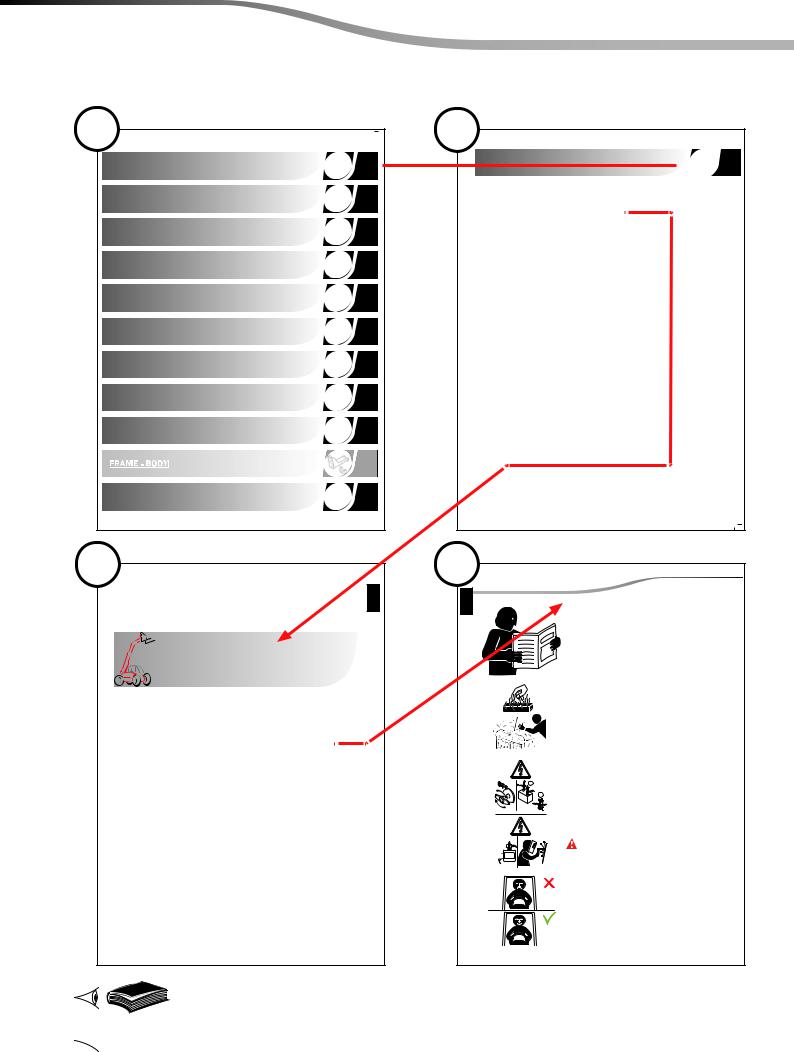
MAINTENANCE POSITION .........................................................3
RULES FOR MAINTENANCE ........................................................4
pages
00
4
General instructions and safety
notice4
00
00
RULES FOR MAINTENANCE
Do not carry out any work on the machine unless you have followed
a suitable training course and have the knowledge required for it.
Make sure you have taken into consideration all the indicator plates
on the machine and in the instruction manual.
Be careful not to burn yourself when touching hot liquids or parts
when operations have to be done before the machine has had
time to cool down.
Before carrying out any operation on an electrically powered
1
component, activate the battery cut-o.
If the telehandler does not have a battery isolation device, disconnect
2
the battery connecters then re-assemble them.
Before carrying out any welding operations, think about
ECU
disconnecting computers.
A machine operating in a contaminated environment should be
specifically equipped. Moreover, local safety notices deal with
maintenance and repair work on such machines.
R
547982 : See the repair manual N° 547982.
70 - HYDRAULIC : See the group N° 70 called «Hydraulic».
GENERAL
ENGINE SPECIFICATION
TRANSMISSION
AXLE
BRAKE
00102030405570808590110
JIB - ACCESS PLATFORM
HYDRAULICS
ELECTRICITY
DRIVER'S CAB
FRAME - BODY
OPTIONS - ATTACHMENTS
GENERAL
GENERAL INSTRUCTIONS AND SAFETY
NOTICE
GENERAL CONTROL AND ADJUSTMENT
00
GENERAL INSTRUCTIONS AND SAFETY NOTICE
00
pages
GENERAL INSTRUCTIONS..........................................................2
SPARE PARTS .....................................................................3
SERVICING AND REPAIR EQUIPMENT...............................................8
(02/05/2013)00-00-M193EN
2
00
00
GENERAL INSTRUCTIONS AND SAFETY NOTICE
GENERAL INSTRUCTIONS
This chapter sets out the safety instructions to be followed when carrying out repairs on an access
platform.
Maintenance or repairs other than those detailed in part: 3 - MAINTENANCE OF THE OPERATOR’S MANUAL
for the platform, are to be carried out by qualied personnel (consult your dealer) and under optimum
safety conditions to maintain the health of the operator and of others, as well as to avoid damage to
the platform.
Insofar that the platform manufacturer does not directly control maintenance or repair operations,
theoperator and the manager in charge of the establishment shall be responsible for the safety of
these processes.
BEWARE OF LEAKS - Diesel fuel or hydraulic uid escaping under high pressure may pierce the
skin and cause serious injury. In the event of injury due to a pressurised liquid jet, immediately
b
consult a doctor.
FRONT and rear are indicated in the gures for ease of understanding.
For information:
PLATFORM TYPEFRONTREAR
ARTICULATEDCounterweightBasket
SCISSORSteering axleSteps
VERTICAL MASTCounterweightBasket
TRUCK-MOUNTED PLATFORMDriver's cabBasket
TELESCOPICBasket extensionSteps
As our policy is one of constant improvement of our products, our range of access platforms may undergo
certain modications, without obligation for us to advise our customers.
(02/05/2013)00-00-M193EN
SPARE PARTS
Our platforms must be serviced using original MANITOU parts.
BY ALLOWING THE USE OF NON ORIGINAL MANITOU PARTS, YOU RISK:
- Legally, to be held responsible in the event of an accident.
- Technically, to cause operating malfunctions or shorten the life of the lift truck.
The use of counterfeit parts or components not approved by the manufacturer, will cause you to loose
the benet of the contractual guarantee. BY USING ORIGINAL MANITOU PARTS FOR MAINTENANCE
OPERATIONS:
YOU BENEFIT FROM OUR KNOW-HOW.
Through its network, MANITOU provides the user with:
GENERAL INSTRUCTIONS AND SAFETY NOTICE
3
00
00
- Know-how and competence.
- The guarantee of high-quality work.
- Original replacement parts.
- Help with preventive maintenance.
- Ecient diagnostic help.
- Improvements due to feedback.
- Operator training.
Only the MANITOU network has detailed knowledge of the design of the access platform and therefore
the best technical ability to provide maintenance.
FOR COMMERCIALLY-AVAILABLE COMPONENTS (CYLINDERS, ELECTRIC PUMP, SPEED CONTROLLER,
CHARGER, ENGINE, ETC.) AND DURING THE PLATFORM GUARANTEE PERIOD:
- Component removal ALLOWED
- Component removal FORMALLY FORBIDDEN AT THE RISK OF INVALIDATING THE GUARANTEE
Original replacement parts are distributed exclusively by MANITOU and its dealer network.
The dealer network list is available on the MANITOU web site: www.manitou.com.
(02/05/2013)00-00-M193EN
4
00
00
GENERAL INSTRUCTIONS AND SAFETY NOTICE
TECHNICAL DOCUMENTATION
READ and UNDERSTAND the contents of the OPERATOR’S MANUAL regarding the platform (this manual
must be stored in the black storage compartment located in the platform basket). COMPLY in particular
with the contents of Chapter 1 - OPERATING AND SAFETY INSTRUCTIONS as well as the sections marked
with a DANGER symbol.
READ and UNDERSTAND the operating and/or safety instructions given by the STICKERS applied to the
platform.
Before starting a procedure given in this REPAIR MANUAL, fully READ it and understand what you have
read.
(02/05/2013)00-00-M193EN
REPAIR PROCEDURES
GENERAL:
POSITION the platform within a horizontal working area that is clean, cleared of any objects and mark
it out. If all of these conditions cannot be met (platform on site, in a cold store, etc.), chock the wheels,
mark the platform and familiarise yourself with the hazards associated with the environment.
SWITCH OFF THE PLATFORM by means of the battery cut-o before starting a procedure (unless otherwise
specied).
The procedure indicates when the weight of a component or an assembly of components exceeds 20kg,
requiring the use of HANDLING EQUIPMENT for removal, insofar as their characteristics (indicated on
the manufacturer's plates or the tare plates) are suitable for the operation to be performed.
For cleaning, use non-ammable solvents approved for that purpose.
GENERAL INSTRUCTIONS AND SAFETY NOTICE
5
00
00
When removing or retting a component, scrupulously follow the procedure step by step. Alwayscomplete
the current stage before commencing the next.
If resistance is felt when removing a component: STOP. Check that the nuts, screws and cables have
been removed and that there is no interference with adjoining components.
The most important factor in the preservation of the working life of the platform is to ensure that its
vital components are kept very clean.
When it is not specied, retting operations consist in performing the removal operations in reverse order.
MECHANICAL COMPONENTS:
Use screws having identical characteristics to the original screws and of an appropriate length.
Insofar that the procedures do not specify the values of the tightening torques to be applied to threaded
fasteners, the appropriate standard values must be used to suit the characteristics of these fasteners.
(02/05/2013)00-00-M193EN
6
00
00
GENERAL INSTRUCTIONS AND SAFETY NOTICE
HYDRAULICS
Certain hydraulic lines ARE UNDER VERY HIGH PRESSURE, even when the platform is not operating.
Inorder to avoid any accidents:
- Follow the hydraulic line decompression procedure before servicing or repairing one of their components.
Certain cylinders are tted with valves that are used to secure the platform the moment the movements
are stopped, by maintaining hydraulic pressure in the chambers of the cylinder. As a result, a chambers of
a cylinder that has been removed might be under VERY HIGH PRESSURE (in excess of 100 bar, inparticular
in the case of the tilt compensation circuit). You should:
- Perform the operations for decompressing the cylinder to be removed.
- Eliminate any pressure from the chambers of a cylinder before it is removed.
Prior to working on a hydraulic component, clean the area immediately around it, provide containers
or rags to recover any uid leakage during removal. Also provide caps and covers to plug openings and
prevent the contamination of the circuit.
Covers, hatches, seals and lters are provided to ensure the purity of the hydraulic uid and prevent
contamination of the circuit. These parts therefore require to be periodically:
- Checked for damage.
- Kept clean.
A cloudy uid indicates a high moisture content, which will lead to oxidation / corrosion of the circuit's
metal components: drain and clean the whole of the circuit, then rell with fresh hydraulic uid.
Should the circuit prove to be contaminated with foreign matter (metal, rubber, etc.), drain and clean
the whole of the circuit then ll with fresh hydraulic uid.
It is not recommended to mix hydraulic uids of dierent types or makes insofar that they cannot be
guaranteed to be of similar composition or viscosity.
Refer to Chapter 3 - MAINTENANCE of the OPERATOR’S MANUAL to select the appropriate oil for the use
of the platform.
(02/05/2013)00-00-M193EN
SYMBOLS
GENERAL:
GENERAL HAZARDThe associated text must be READ and UNDERSTOOD
ELECTRICAL HAZARDThe associated text must be READ and UNDERSTOOD
HIGH TEMPERATURE HAZARDThe associated text must be READ and UNDERSTOOD
GENERAL INSTRUCTIONS AND SAFETY NOTICE
before continuing to the next stage of the procedure.
7
00
00
HYDRAULIC PRESSURE HAZARDThe associated text must be READ and UNDERSTOOD
before continuing to the next stage of the procedure.
MINIMUM WEIGHTIndicated in removal procedures, this sign enables
the selection of the appropriate handling equipment.
647400EN Refer to Operator’s Manual no. 647400EN.
647400 Refer to spare parts catalogue no. 647400.
80-08-M.193EN Refer to Chapter no. 80-08-M.193EN of the current repair manual.
§ B - 1 Refer to paragraph B - 1 of the current chapter.
(A1-1) (Figure A1 - Item 1)
Indicates attachment points or bearing surfaces (for lift truck forks) to be used
during removal operations.
(02/05/2013)00-00-M193EN
8
00
00
GENERAL INSTRUCTIONS AND SAFETY NOTICE
SERVICING AND REPAIR EQUIPMENT
- Tool box.
- MANITOU hydraulic kit: Part no. to be selected from catalogue 647400.
- Male and female plug adapters for plugging hydraulic hoses and couplers.
- Calibrator: Part no. according to platform type, see the relevant chapter.
- Multimeter.
(02/05/2013)00-00-M193EN
GENERAL CONTROL AND ADJUSTMENT
00
pages
STANDARD TIGHTENING TORQUES.................................................2
(16/04/2012)00-04-M193EN
2
00
00
GENERAL CONTROL AND ADJUSTMENT
STANDARD TIGHTENING TORQUES
Standard tightening torque to be used when not otherwise indicated in the removal and refitting
operations:
- The following tightening torques are given for hexagon head screws without flanges and
cylinder head hexagon socket screws.
- The torques are given for a friction coecient μ = 0,20 corresponding to dry-tted zinc-plated
fasteners and for torque tools having a ± 20% class C tightening torque accuracy (equivalent
to pneumatic screwdrivers).
NF E25-030-1 Screw / Nut connection:
Tightening torque in N.m (±20%)
Ø x "coarse" pitchGrade 8.8Grade 10.9Ø x “ne” pitchGrade 8.8Grade 10.9
M3 x 0,511,5---
M4 x 0,72,43,5---
M5 x 0,84,87,1---
M6 x 18,212,1---
M8 x 1,252030M8 x 12232
M10 x 1,54059
M12 x 1,7569102
M14 x 2111163M14 x 1,5123181
M16 x 2175256M16 x 1,5190279
M18 x 2,5240352M18 x 1,5279410
M20 x 2,5341501M20 x 1,5391574
M22 x 2,5470691M22 x 1,5531780
M24 x 3588864M24 x 2659967
M27 x 38741284M27 x 29651418
M30 x 3,511811735M30 x 213511984
M33 x 3,516142371M33 x 218212674
M36 x 420683037---
M10 x 1,254363
M10 x 14668
M12 x 1,574108
M12 x 1,2578115
For hexagon screws with anges:
Apply a torque of accuracy + 10%.