


MANUALEQUIPOSPESADOS.COM
MAINTENANCE INSTRUCTIONS
ELECTROHYDRAULIC ACTUATION MODULE
TYPE EMS
MAINTENANCE
SUMMARY
1.Introduction
1.1Foreword
1.2Safety instructions
2.Troubleshooting
3.Fondamental rules
3.1General information concerning electrohydraulic actuation module connection
4.Removal / installation of electrohydraulic actuation module
4.1General recommendations
4.2Removal of a single electrohydraulic actuation module
4.3Removal of one of several electrohydraulic actuation modules assembled together
4.4Electrohydraulic actuation module assembly
4.5Removal / disassembly of the electrohydraulic transformation stage
5.Removal / assembly of connecting flange and filter
5.1Connecting flange removal / assembly
5.2Filter replacement
6.Neutral position adjustement
7.Start-up procedures
Type : electrohydraulic actuation module EMST = EMSP
1. INTRODUCTION
1.1 - Foreword
It is recommended that only qualified personnel perform the installation, connection and maintenance of this device, and that all operations be carried out in compliance with the technical standards in force and the cleanliness regulations specific to this type of installation.
To ensure maximum performance and safety during maintenance operations we advise you to
READ THIS MANUAL THOROUGHLY
All informations, illustrations, instructions and characteristics contained in this document are based on the latest product information available at the time of publication. In its attempts to maintain a high-quality product, MANITOU reserves the right to make design or technical modifications at any time and without prior notification.
1.2 - Safety instructions
Please pay a particular attention to the signals of the safety alertsand special instructions in this manual. They are indicated in the following manner :
Indicates informations or instructions which must be followed to guarantee your safety during operations.
CAUTION : WARNING AGAINST POSSIBLE EQUIPMENT DAMAGE.
NOTE : Useful information.
14
MANUALEQUIPOSPESADOS.COM
MAINTENANCE INSTRUCTIONS - Troubleshooting
Observed problems |
Probable cause |
Additional verifications |
Solutions |
|
|
|
|
Absence of movement on all |
1. Supply voltage insufficient. |
Check minimum supply |
|
the proportional functions. |
|
voltage 9V of the proportional |
|
|
|
control unit. |
|
|
|
|
|
|
2. Pilot pressure insufficient. |
Verify the supply pressure of |
|
|
|
the pilot circuit of the |
|
|
|
proportional control units |
|
|
|
minimum 15 bar. |
|
|
|
|
|
|
3. Sealing of the protection |
Clean the filter. |
Remove filter of the hydraulic |
|
filter of the proportional |
|
supply unit |
|
controls. |
|
(page 22). |
|
|
|
|
Absence or defect of |
1. Absence of signal of the |
Check the signal of the mani- |
Verify the connections and |
movement on a proportional |
proportional control of the |
pulator towards the proportio- |
clusters between proportional |
function. |
distributor. |
nal control units. |
control unit and manipulator. |
|
|
Value = 2.5 volts if manipula- |
If OK, change the manipula- |
|
|
tor knob is at neutral. |
tor. |
|
|
|
|
|
2. Signal defect of the propor- |
Ensure that the signal voltage |
If value outside of limits, |
|
tional control of the distri- |
comprises of between 1 and |
change the manipulator. |
|
butor. |
4 volts while using the control |
|
|
|
knob of the manipulator. |
|
|
|
|
|
|
3. Insufficient voltage of the |
Verify control voltage 5 volts |
If voltage nil or insufficient, |
|
proportional control units of |
provided by the proportional |
replace the proportional |
|
the distributor. |
control units to the manipula- |
control unit |
|
|
tor. |
(pages 17, 18, 19). |
|
|
|
|
Untimely movement with pro- |
Signal defect of the proportio- |
Check the signal of the mani- |
Verify the connections and |
portional control of the mani- |
nal controls of the manipula- |
pulator towards the proportio- |
clusters between proportional |
pulator in neutral. |
tor. |
nal control units. |
control unit and manipulator. |
|
|
Value = 2.5 volts if manipula- |
If OK, change the manipula- |
|
|
tor knob is at neutral. |
tor. |
|
|
|
|
Sudden or irregular move- |
Protection filter partially sea- |
Clean the filter. |
Remove filters of hydraulic |
ment on all the proportional |
led. |
|
supply unit |
functions. |
|
|
(page 22). |
|
|
|
|
Sudden or irregular move- |
Looking or jamming of the |
|
Replace the proportional |
ment on a single proportional |
position sensor of the propor- |
|
control unit (pages 17, 18, |
function. |
tional control unit. |
|
19). |
|
|
|
|
Sudden or irregular move- |
Looking or jamming of the |
|
Replace the proportional |
ment in a single direction on |
pilot drawer of the proportio- |
|
control unit (pages 17, 18, |
a proportional function. |
nal control unit. |
|
19). |
|
|
|
|
15
MANUALEQUIPOSPESADOS.COM
MAINTENANCE INSTRUCTIONS - Troubleshooting
Observed problems |
Probable cause |
Additional verifications |
Solutions |
|
|
|
|
|
|
Symmetry defect of the |
Shift of the neutral position of |
|
Adjust the neutral position of |
|
control of a proportional func- |
the position sensor. |
|
the position sensor |
|
tion. |
|
|
(page 24). |
|
|
|
|
|
|
Oil leak between two propor- |
Imperviousness defect of the |
|
Change the packing |
|
tional control units. |
piping of the pilot circuit bet- |
|
(pages 17, 18, 19). |
|
|
ween the units. |
|
|
|
|
|
|
|
|
Oil leak between electro- |
1. Packing damaged. |
|
Change the packing |
|
hydraulic and mechanical |
|
|
(page 20). |
|
2. Pilot pressure too high. |
Verify that the supply pressu- |
|||
interface of the proportional |
|
|||
|
re of the pilot circuit does not |
|
||
control units. |
|
|
||
|
exceed 35 bar. |
|
||
|
|
|
||
|
|
|
|
3. FONDAMENTAL RULES
3.1 - General information concerning electrohydraulic actuation module connection
Hydraulic
When removing the electrohydraulic actuation module, all openings must be plugged immediately to prevent any contamination of the hydrailic system.
Check the hydraulic installation’s oil quality and filtration capacity during all servicing / maintenance operations.
When replacing the electrohydraulic actuation module, remove the plastic plugs from the openings and lines just before making the connections.
Do not tighten connectors to a torque greater than that specified in the assembly instructions. The use of Teflon tape, hemp and joint filler is prohibited.
Hydraulic lines and connections must not be under any strain whatsoever.
Electric
All along the operations, pay attention not to damage the cables and electrical connections.
Check that there is no residual voltage across the cables and electrical connections.
16
MANUALEQUIPOSPESADOS.COM
MAINTENANCE INSTRUCTIONS
4. REMOVAL / INSTALLATION OF THE ELECTROHYDRAULIC ACTUATION MODULE
4.1 - General recommendations
CAUTION : BEFORE REMOVING THE CONTROL BACK FROM THE MACHINE, THE BLOCK AND ITS SURROUNDINGS MUST BE THOROUGHLY CLEANED (NOTE: DO NOT DIRECT THE JET OF A PRESSURE WASHING UNIT DIRECTLY AT THE UNIT).
NO IMPURITIES MUST ENTER THE HYDRAULIC SYSTEM. PLASTIC PLUGS ARE TO BE FITTED ON LINES AND ORIFICES IMMEDIATELY FOLLOWING THEIR REMOVAL.
Wear protective clothing and use suitable equipment to prevent accidents, particularly concerning the hydraulic fluid.
Use the lifting eyes and suitable handling equipment.
Set all actuators connected to the machine in neutral position (on the ground, at lower limit...) to avoid accidents which could result from uncontrolled movements of the equipment when the hydraulic system is deconnected.
With the machine off, release the pressure remaining in the system by manipulating all of the distribution spools. This can be performed by moving the handle in all directions.
17
MANUALEQUIPOSPESADOS.COM
MAINTENANCE INSTRUCTIONS
4.2- Removal of a single electrohydraulic actuation module
Machine off :
-place all of the machine’s actuators connected to the control block in neutral position,
-release stored pressure by operating all the spools (move the handler in all directions).
NOTE : Install a vacuum pump on the tank of the machine to limit oil leakage when connections are removed.
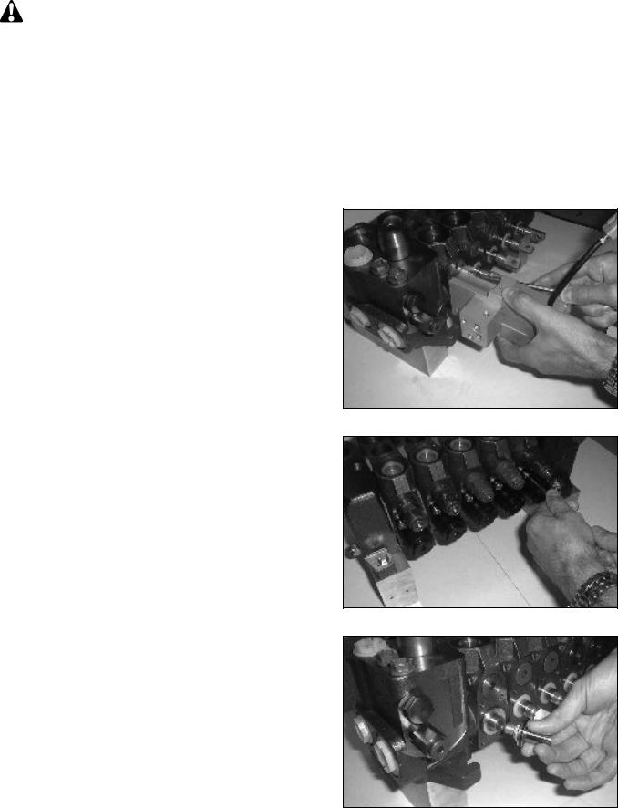
After disconnecting the lines from the electrohydraulic actuation module, immediately fit the sealing plugs. Make sure to collect any possible oil leakage in a suitable receptacle.
Unscrew the mounting screw using an allen wrench M5.
Reassembly : torque : 15 ± 1 N.m.
Pull the electrohydraulic actuation module backward parallely to the spool axis in order to release the operation piston.
Remove the cover of spring return system on the opposite side of the spool (see SX14 Maintenance instructions § 6.3).
Unscrew the positionning piston from the distributing spool using a 19mm wrench on piston side and a M5 Allen wrench on spring side.
Reassembly : Apply 2 drops of loctite 242 onto the piston thread.
torque : 10 ± 1 N.m.
18

MANUALEQUIPOSPESADOS.COM
MAINTENANCE INSTRUCTIONS
Remove and replace the tightness seal lying between the actuator and the control valve.
Remove the centering plater.
NOTE : Do not remove the spool from the control valve.
Reassemble in reverse order.
Adjust the neutral position (see § 6).
19
MANUALEQUIPOSPESADOS.COM
MAINTENANCE INSTRUCTIONS
4.3- Removal of one of several electrohydraulic actuation modules assembled together
Machine off :
-Place all of the machine’s actuators connected to the control block in neutral position.
-Release stored pressure by operating all the spools (move the handler in all directions).
NOTE : Install a vacuum pump on the tank of the machine to limit oil leakage when connections are removed.
After disconnecting the lines from the electrohydraulic actuation module, immediately fit the sealing plugs. Make sure to collect any possible oil leakage in a suitable receptacle.
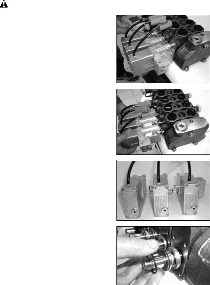
To remove an intermediary or terminal electrohydraulic actuation module, it is required to remove the complete module assembly.
Unscrew all the mounting screws of each electrohydraulic actuation modules using an Allen wrench M5 (see § 4.2).
Reassembly : torque : 15 ± 1 N.m.
Pull the module assembly backward parallely to the spool axis in order to release the opertion piston.
Place the modules on a clean and clear surface in order to pull them apart.
Reassembly :
-Remove and replace the carry-over pipes of the faulty module.
-Replace the faulty electrohydraulic actuation module.
-Replace all the tighteness seals lying between the actuators ans their control valve.
-Reassemble in reverse order.
-Adjust the neutral position (see § 6).
20
MANUALEQUIPOSPESADOS.COM
MAINTENANCE INSTRUCTIONS
4.4 - Electrohydraulique actuation module assembly
Check the cleanliness of the contact faces prior to reassemble.
Replace the carry-over pipes that have been removed. Replace the O-ring between the electrohydraulic actuation module and the control valve element.
Reassemble the module in the reverse order of operations described in § 4.2 and 4.3.
4.5- Removal / disassembly of the electrohydraulic transformation stage
NOTE : The electrohydraulic actuation module does not need to be removed to perform this operation.
Machine off :
-Place all of the machine’s actuators connected to the control block in neutral position.
-Release stored pressure by operting all the spools.
NOTE : Install a vacuum pump on the tank of the machine to limit oil leakage when connections are removed.
After disconnecting the lines from the electrohydraulic actuation module, immediately fit the sealing plugs. Make sure to collect any possible oil leakage in a suitable receptacle.
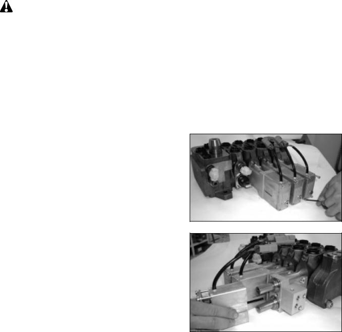
Unscrew the 4 mounting screws using an allen wrench M3.
Reassembly : torque : 3 to 3,5 N.m.
Remove the electrohydraulic transformation stage by gently pulling it backward parallely to the spool axis until the rod of the position sensor is completly extracted.
NOTE : The removal of the 4 mounting screws of the electrohydraulic transformation stage releases the PCB tightened protecting cover. Avoid all risk of pollution, humidification or impacts on electronics and hydraulics parts during the operations.
Once correctly installed, the unit can be placed into operation :
-Check the condition of line connector seals.
-Check the condition of electric wires.
-Connect the lines to the block as per the connecting diagram and tighten to the torque specification (refer to the table in the Data sheat).
-Ensure that hoses are not twisted nor rub.
21
MANUALEQUIPOSPESADOS.COM
MAINTENANCE INSTRUCTIONS
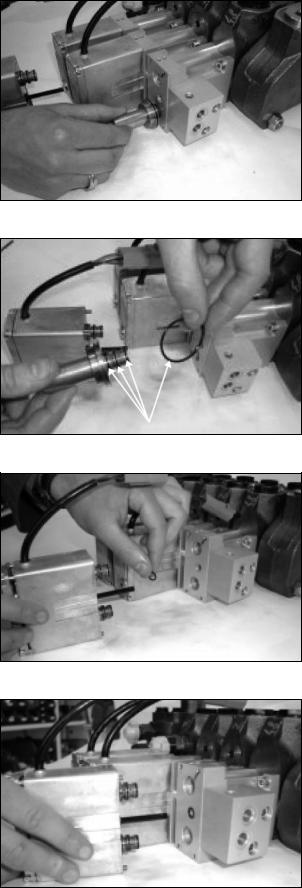
Remove one or both electrohydraulic valve(s).
NOTE : This operation is to be performed only in the case of an external leakage noticed around the tightness seal between the valve and the housing.
Reassembly :
-replace the external tightness seals on the valves
-fit the valve(s) into its (their) housing(s).
Replace the external tightness seal of the rod (or sensor O-ring).
NOTE : Place the sensor O-ring in its groove on the mechanical interface side prior to assembly.
Reassemble the electrohydraulic transformation stage in reverse order.
Joints d'étanchéité
22

MANUALEQUIPOSPESADOS.COM
MAINTENANCE INSTRUCTIONS
5.REMOVAL / ASSEMBLY OF CONNECTING FLANGE AND FILTER
Machine off :
-Place all of the machine’s actuators connected to the control block in neutral position.
-Release stored pressure by operating all the spools.
NOTE : Install a vacuum pump on the tank of the machine to limit oil leakage when connections are moved.
After disconnecting the lines from the electrohydraulic actuation module, immediately fit the sealing plugs. Make sure to collect any possible oil leakage in a suitable receptacle.
5.1 - Connecting flange removal / assembly
Unscrew the 2 mounting screws using an allen wrench M5.
Reassembly : torque : 11 ± 1 N.m.
Remove the connecting flange. Pull the connecting flange backward parallely to the screw axis in order to release the carry-over pipes.
Reassemly :
-Replace carry-over pipes.
-Reassemble parts in reverse order.
5.2 - Filter replacement
Unscrew the filter in the port P using a flat screw driver.
Reassembly : hand tight the filter in port P.
23
MANUALEQUIPOSPESADOS.COM
MAINTENANCE INSTRUCTIONS
6. NEUTRAL POSITION ADJUSTMENT
NOTE : To perform this operation, the control block does not need to be removed from the machine, nor the electrohydrauic actuator module from the control valve.
Machine off :
-Place all of the machine’s actuators connected to the control block in neutral position.
-Release stored pressure by operating all the spools (move the handler in all directions).
Locate and remove the inspection plug on the lower side of the actuation module rear cover.
Switch on the electrical power (12VDC or 24VDC) only (no hydraulic power).
The assistance pressure of 35 bar must absolutely be decompressed.
Locate the adjusting trimmer inside and the green LED underneath. The green LED will turn on by the time the ”mechanical zero” of the spool matches the ”electrical zero” of the electronic setup.
Using a flat and thin screwdriver, turn the trimmer clockwise or counterclockwise until the green LED turns on.
24

MANUALEQUIPOSPESADOS.COM
MAINTENANCE INSTRUCTIONS
7. START UP PROCEDURES
Machine off :
-Place all of the machine’s actuators connected to the control block in neutral position.
-Release stored pressure by operating all the spools. Make sure that the remote control is switched off while starting up the engine and before the hydraulic pump is engaged.
Start up the engine and engage the oil pump. Turn on the remote control system.
CAUTION
THE ELECTROHYDRAULIC PROPORTIONAL SYSTEM IS DESIGNED AND QUALIFIED FOR LOW TEMPERATURE OPERATION UP TO -40°C. FOR OIL TEMPERATURE LESS THAN -15°C, ACTUATORS MOVEMENTS MAY INITIALLY RESULT SLOW AND JERKY. IT IS STRONGLY RECOMMANDED THAT COLD WEATHER START-UP ARE FOLLOWED BY PROPER OIL HEATING PROCEDURES.
Engage the remote control device and slowly vary the control signal making sure that no external obstacle can be hit in case of unadverted movements.
In response to a variable signal generated by the remote control device, the selected machine’s function must smoothly accelerate / decelerate, showing good stability and repeatability.
When one remote control function at a time is engaged, only the corresponding machine function must respond, while all the other machine functions remain at rest.
25
MANUALEQUIPOSPESADOS.COM
50 |
Transmission control and adjustment |
|
6 - SPRUNG-ON 4 WHEEL DRIVE DIS-ASSEMBLY AND RE-ASSEMBLY
DIS-ASSEMBLY
6-1 |
|
|
6-2 |
|
|
|
|
|
|
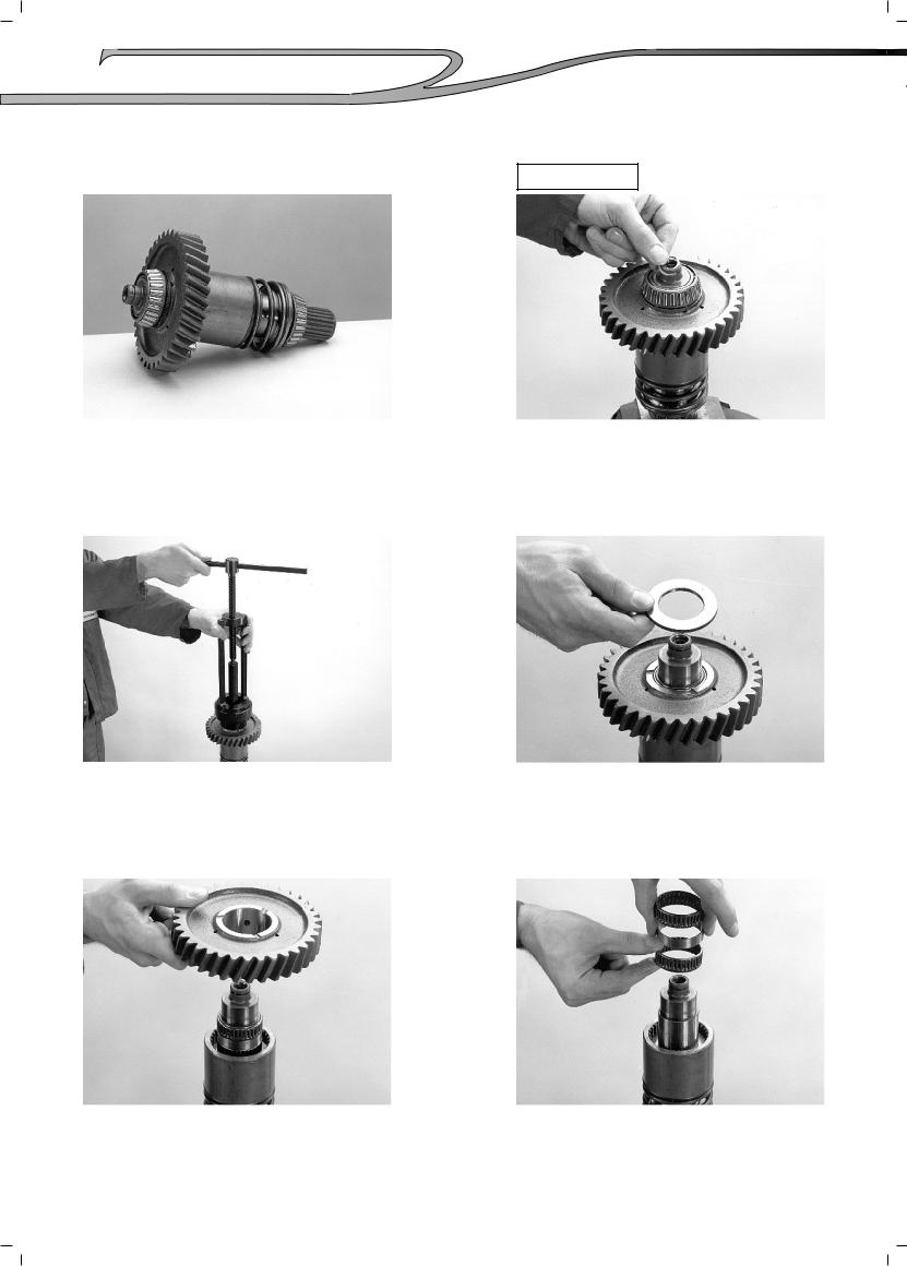
The sprung on 4 wheel drive assembly.
Position the shaft in a soft jawed vice and remove the sealing ring.
6-3 |
|
|
6-4 |
|
|
|
|
|
|
Using the appropriate bearing puller |
Remove the thrust washer. |
remove the rear bearing. |
|
6-5 |
|
|
6-6 |
|
|
|
|
|
|
Remove the 4 wheel drive gear.
Remove the two needle bearings and spacer.
(01/07/2008)

MANUALEQUIPOSPESADOS.COM
Transmission control and adjustment |
51 |
|
6-7 |
|
|
6-8 |
|
|
|
|
|
|
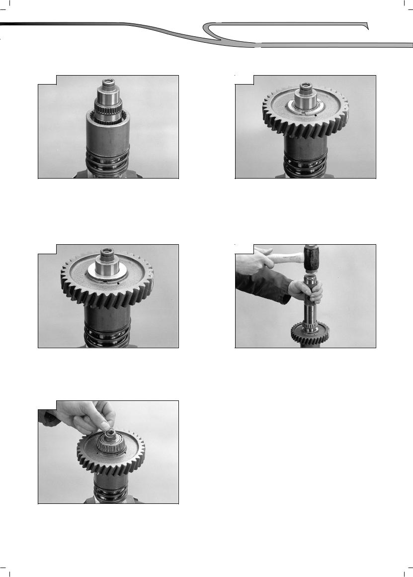
Invert the shaft and using the appropriate bearing puller remove the front bearing.
6-9
Remove the circlip, retainer, and spring.
6-11
Remove the piston seal and «O»ring from the shaft and discard.
Using the appropriate tool compress the spring and release the circlip.
6-10
Remove the piston drum assembly.
6-12
Remove and discard the piston seal and «O»ring from the piston drum.
(01/07/2008)

MANUALEQUIPOSPESADOS.COM
52 |
Transmission control and adjustment |
|
RE-ASSEMBLY
6-13
Fit a new «O»ring and sealing ring to the shaft.
See (fi g. 6-11).
6-15
Lubricate the seals with a light grease and refi t the piston to the shaft.
6-17
Using the appropriate tool compress the spring and retainer and refi t the circlip.
6-14
Fit a new «O»ring and sealing ring into the piston. Bend the sealing ring into a heart shape as shown to assist assembly.
6-16
Replace the piston spring and retainer.
6-18
Using an appropriately sized tube refit the front bearing.
(01/07/2008)
MANUALEQUIPOSPESADOS.COM
6-19
Invert the shaft and refit the two needle bearings and spacer as shown.
6-21
Replace the thrust washer.
6-23
Fit a new sealing ring.
Transmission control and adjustment |
53 |
|
6-20
Replace the 4 wheel drive gear.
6-22
Using an appropriately sized tube replace the rear bearing.
(01/07/2008)
MANUALEQUIPOSPESADOS.COM
54 |
Transmission control and adjustment |
|
7 - PERMANENT 4 WHEEL SHAFT DIS-ASSEMBLY AND RE-ASSEMBLY
DIS-ASSEMBLY
7-1 |
|
|
7-2 |
|
|
|
|
|
|
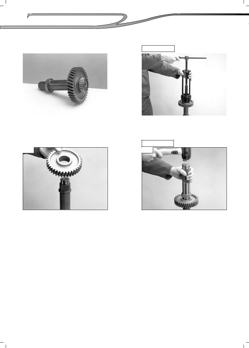
The permanent 4 wheel drive shaft.
7-3
Using the appropriate bearing puller remove the front and rear bearings.
RE-ASSEMBLY
7-4
Remove the 4 wheel drive gear.
Replace the 4 wheel drive gear using stop threaded product (P / N° 548110), on the shaft splines . Then using a suitably sized tube re-fit the front and rear bearings.
(01/07/2008)
MANUALEQUIPOSPESADOS.COM
Transmission control and adjustment |
55 |
|
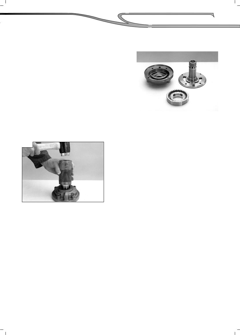
8 - DIS-ASSEMBLY AND RE-ASSEMBLY OF THE OIL PUMP
Note : Individual components of the oil |
8-1 |
|
pump are non serviceable. The pump |
|
|
may, however, be stripped for cleaning |
|
|
and examination purposes. |
|
|
|
|
|
View showing a dismantled pump assembly.
8-2
The pump oil seal may be replaced using an approprietely sized tube.
(01/07/2008)
MANUALEQUIPOSPESADOS.COM
56 |
Transmission control and adjustment |
|
9 - DIS-ASSEMBLY AND RE-ASSEMBLY OF THE VALVE
Nota : Dis-assembly of the control valve |
9-1 |
|
is not generally recommended |
|
|
as, with the exception of the |
|
|
solenoids, individual parts are |
|
|
non serviveable. It may however |
|
|
be dismantled for cleaning and |
|
|
examination. |
|
|
|
|
|
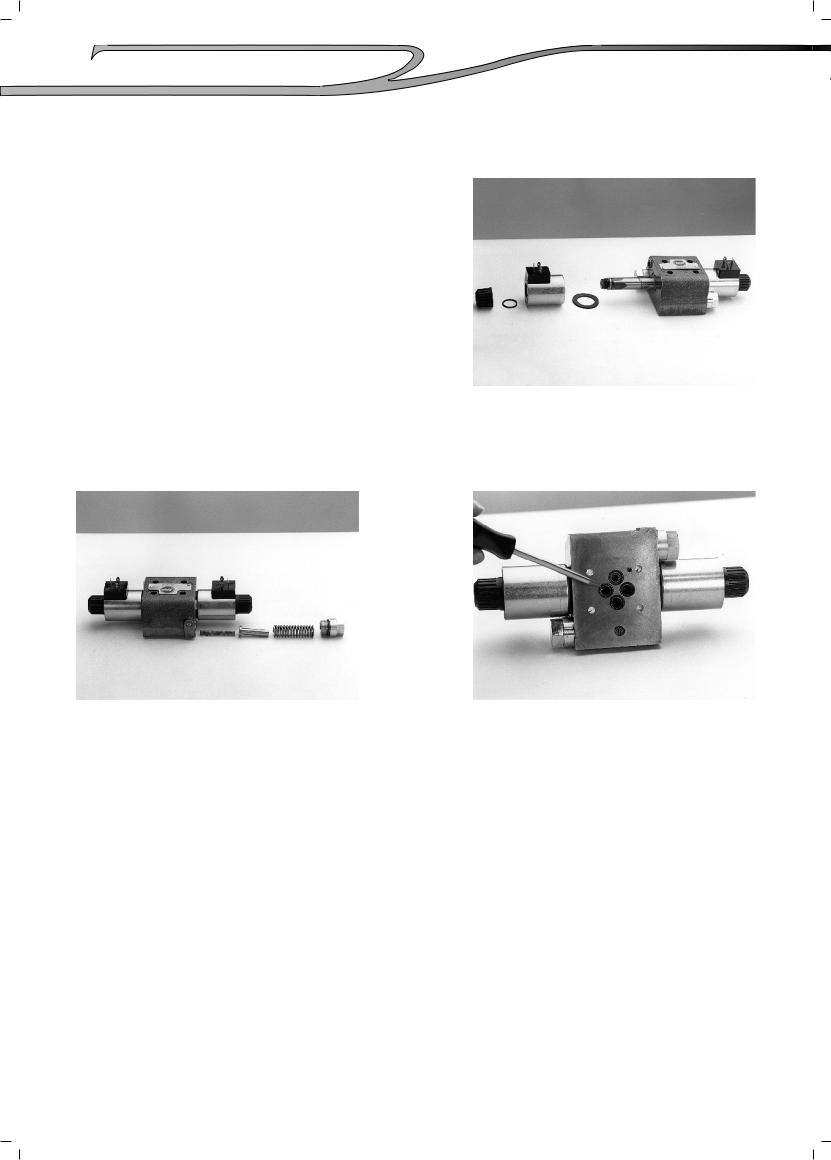
The retaining nut, coil and washers removed.
9-2 |
|
|
9-3 |
|
|
|
|
|
|
The modulation components removed. |
There are 4 «O»rings fitted to the |
|
underside of the valve which may be re- |
|
newed if necessary. |
(01/07/2008)
MANUALEQUIPOSPESADOS.COM
Transmission control and adjustment |
57 |
|
10 - GEAR LEVER HOUSING DIS-ASSEMBLY AND RE-ASSEMBLY
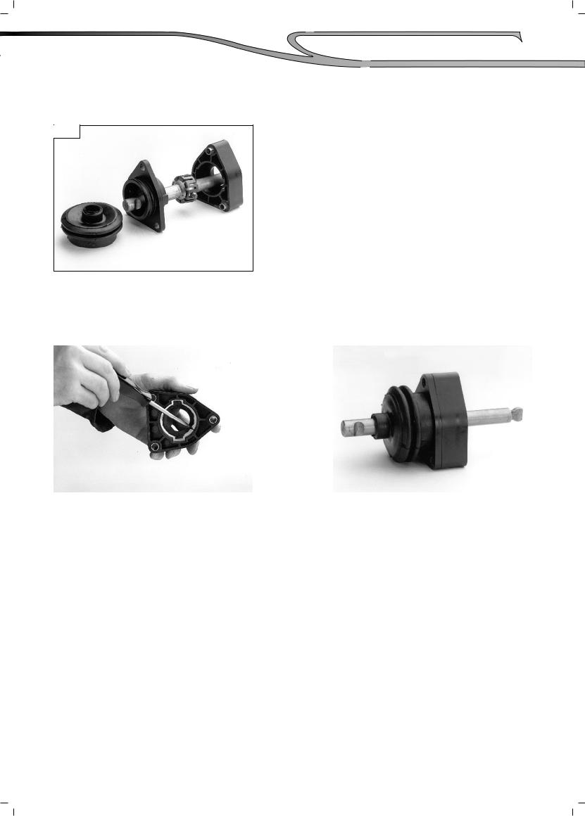
10-1
Remove the plastic ties from the rubber gaiter and pull the assembly apart as shown.
Nota : Before re-assembly remove all traces of old sealant from the joint faces.
10-2 |
|
|
10-3 |
|
|
|
|
|
|
Apply a airtightness product (P / N° 562228) to the sealing face as shown.
Lubricate the ball seating with a light grease and push the two halves of the assembly together. Secure the rubber gaiter with two new plastic ties.
(01/07/2008)
 Loading...