

Page 1

CATALOG 648226AS
R/
11-10
MANITOU NORTH AMERICA, INC.
6401 IMPERIAL DRIVE
Waco, TX 76712--6803
For Parts Orders contact your Manitou North America Dealer or call:
Manitou North America, Parts Dept. 800--425--3727 or (254) 799--0232
Parts Dept. Fax: (254) 867--6504 Website: www.manitou--na.com
CALIFORNIA PROPOSITION 65 WARNING
Diesel Engine Exhaust and some of its constituents are known to the State of
California to cause cancer, birth defects or other reproductive harm.
MRT1432
400°
M SERIES E-2
3B6 SERIES INSTRUMENTS
S/N: 411048 AND BELOW
OPERATOR/SERVICE
MANUAL
THIS OPERATOR’S MANUAL MUST BE KEPT IN THE LIFT TRUCK. IT MUST BE READ AND
UNDERSTOOD BY OPERATORS.
Page 2

Page 3

- INTRODUCTION TO SAFETY -
- ROUGH TERRAIN FORKLIFT TRUCK
GENERAL SAFETY STANDARDS - - - I
- SAFTETY MESSAGES - - - - - - - - - - - - - - - - - - - - - - - - - - VII
- SAFETY DECALS - - - - - - - - - - - - - - - - - - - - - - - - - - - - - - VIII
R03-04
Page 4

Page 5

ROUGH TERRAIN FORKLIFT TRUCK
GENERAL SAFETY ST
ANDARDS
I
Page 6

ROUGH TERRAIN FORKLIFT TRUCK GENERAL SAFETY STANDARDS
STUDY THE OPERATOR/SERVICE MANUALS
The information in this manual provides general instructions for the safe operation and maintenance of your
forklift truck. This information is vital and must be clearly understood by the operator and serviceman. Study
this manual and the Rough Terrain Forklift Safety Manual (part no. 422494) thoroughly and carefully before
operating or servicing your forklift. Contact your dealer or Manitou North America, Inc. if you have any questions concerning your forklift, its operation, service or parts. Keep both manuals in the literature box on the
forklift available for reference. If either manual becomes illegible or is missing, contact your dealer for replacements immediately. This manual cannot cover every situation that might result in an accident. It is the responsibility of the operator to always remain alert for potential hazards and be prepared to avoid them!
ADDITIONAL RECOMMENDED LITERATURE:
ANSI / ITSDF B56.6 is the national consensus standard for rough terrain forklift trucks. It contains rules about
forklift safety, maintenance, safe operation, training, and supervision. Forklift owners should learn this standard and make it available for their operators, service personnel, and supervisors. These standards can be
obtained, free of charge, from the Industrial Truck Standards Development Foundation (ITSDF) on their website at www.itsdf.org. The following references are examples from the standard, addressing forklift operators:
A.) OPERATOR TRAINING QUALIFICATIONS
1.) The user shall ensure that operators understand that safe operation is the operator’s responsibility. The
user shall ensure that operators are knowledgeable of, and observe, all safety rules and practices.
2.) Create an effective operator training program centered around user company’s policies, operating conditions, and rough terrain forklift trucks. The program should be presented completely to all new operators and
not be condensed for those claiming previous experience.
3.) Information on operator training is available from several sources, including rough terrain forklift truck manufacturers, users, government agencies, etc.
4.) An operator training program should consist of the following:
a.) careful selection of the operator, considering physical qualifications, job attitude, and aptitude;
b.) emphasis on safety of stock, equipment, operator, and other personnel;
c.) citing of rules and why they were formulated;
d.) basic fundamentals of rough terrain forklift truck and component design as related to safety, e.g.,
in.-lb (N-m) loading, mechanical limitations, center of gravity, stability, etc.;
e.) introduction to equipment, control locations, and functions. Explain how they work when used
properly and problems when used improperly.
f.) supervise practice on operating course remote from normal activity and designed to simulate
actual operations, e.g., lumber stacking, elevating shingles to the roof, etc.;
g.) oral, written, and operational performance tests and evaluations during and at completion of the
course;
h.) refresher courses, which may be condensed versions of the primary
course, and periodic “on job” operator evaluation;
i.) understanding of nameplate data and operator instructions and warning information appearing on
the rough terrain forklift truck.
B.) GENERAL SAFETY PRACTICES
1.) Rough terrain forklift trucks can cause injury if improperly used or maintained.
2.) Only authorized operators trained to adhere strictly to all operating instructions shall be permitted to oper-
ate rough terrain forklift trucks. Unusual operating conditions may require additional safety precautions, training, and special operating instructions.
3.) Modifications and additions which affect capacity or safe operation shall not be preformed without the man-
ufacturer’s prior written approval. Where such authorization is granted, capacity, operation, and maintenance
instruction plates, tags, or decals shall be changed accordingly.
4.) If the rough terrain forklift truck is equipped with front end attachment(s) or optional forks, the user shall see
that the truck is marked to identify the forks or attachment(s), show the approximate weight of the truck and
fork or attachment combination, and show the capacity of the truck with forks or attachment(s) at maximum
elevation with load laterally centered.
5.) The user shall see that all nameplates and caution and instruction markings are in place and legible.
6.) The user shall consider that changes in load dimension may affect rough terrain forklift truck capacity.
II
Page 7

ROUGH TERRAIN FORKLIFT TRUCK GENERAL SAFETY ST
ANDARDS (cont.)
B.) GENERAL SAFETY PRACTICES (cont.)
7.) Where steering can be accomplished with either hand and the steering mechanism is of a type that prevents road reactions from causing the handwheel to spin (power steering or equivalent), steering knobs may
be used. When used, steering knobs shall be of a type that can be engaged by the operator’s hand from the
top and shall be within the periphery of the steering handwheel.
8.) Experience has shown that rough terrain forklift trucks which comply with stability requirements are stable
when properly operated. However, improper operation, faulty maintenance, or poor housekeeping may contribute to a condition of instability and defeat the purpose of the requirements.
9.) Users shall give consideration to special operating conditions. The amount of forward and rearward tilt to
be used is governed by the application. Although the use of maximum rearward tilt is allowable under certain
conditions, such as traveling with the load lowered, the stability of a rough terrain forklift truck as determined
by standardized tests does not encompass consideration for excessive tilt at high elevations or the operation
of trucks with excessive off-center loads.
10.) Some of the conditions which may affect stability are ground and floor conditions, grade, speed, loading
(rough terrain forklift trucks equipped with attachments behave as partially loaded trucks even when operated
without a load on the attachment), dynamic and static forces, improper tire inflation, and the judgement exercised by the operator.
C.) OPERATING SAFETY RULES AND PRACTICES
1.) Safe operation is the responsibility of the operator.
2.) This equipment can be dangerous if not used properly. The operator shall develop safe working habits and
also be aware of hazardous conditions in order to protect himself, other personnel, the rough terrain forklift
truck, and other material.
3.) The operator shall be familiar with the operation and function of all controls and instruments before undertaking to operate the rough terrain forklift truck.
4.) Before operating any rough terrain forklift truck, truck operators shall have read and be familiar with the
operator’s manual for the particular truck being operated.
5.) Before starting to operate the rough terrain forklift truck:
a.) be in operating position and fasten seat belt;
b.) place directional controls in neutral;
c.) apply brakes;
d.) start engine.
6.) Do not start or operate the rough terrain forklift truck, any of its functions, or attachments from any place
other than the designated operator’s position.
7.) Keep hands and feet inside the operator’s designated area or compartment. Do not put any part of the
body outside the operator compartment of the rough terrain forklift truck.
8.) Never put any part of the body into the mast structure or between the mast and the rough terrain forklift
truck.
9.) Never put any part of the body within the reach mechanism of the rough terrain forklift truck or other attach-
ments.
10.) Understand rough terrain forklift limitations and operate the truck in a safe manner so as not to cause injury
to personnel.
11.) Do not allow anyone to stand or pass under the elevated portion of any rough terrain forklift truck, whether
empty or loaded.
12.) Do not permit passengers to ride on rough terrain forklift trucks.
13.) Check clearance carefully before driving under electrical lines, bridges, etc.
14.) A rough terrain forklift truck is attended when the operator is less than 25 ft (7.6m) from the truck, which
remains in his view.
15.) A rough terrain forklift truck is unattended when the operator is 25ft (7.6m) or more from the truck, which
remains in his view, or whenever the operator leaves the truck and it is not in his view.
16.) Before leaving the operator’s position:
a.) bring rough terrain forklift truck to a complete stop;
b.) place directional controls in neutral;
c.) apply the parking brake;
d.) lower load-engaging means fully, unless supporting an occupied elevated platform;
e.) stop the engine;
f.) if the rough terrain forklift truck must be left on an incline, block the wheels;
g.) fully lower the load-engaging means.
17.) Maintain a safe distance from the edge of ramps, platforms, and other similar working surfaces.
18.) Do no move railroad cars or trailer with a rough terrain forklift truck.
III
Page 8

ROUGH TERRAIN FORKLIFT TRUCK GENERAL SAFETY ST
ANDARDS (cont.)
C.) OPERATING SAFETY RULES AND PRACTICES (cont.)
19.) Do not use a rough terrain forklift truck for opening or closing railroad car doors.
20.) In areas classified as hazardous, use only rough terrain forklift trucks approved for use in those areas.
21.) Report all accidents involving personnel, building structures, and equipment to the supervisor or as
directed.
22.) Do not add to, or modify, the rough terrain forklift truck.
23.) Do not block access to fire aisles, stairways, and fire equipment.
24.) For rough terrain forklift trucks equipped with a differential lock, the lock should not be engaged when driv-
ing on the road or at high speeds or when turning. If the lock is engaged when turning, there could be loss of
steering control.
25.) Observe all traffic regulations including authorized speed limits. Under normal traffic conditions, keep to
the right, maintain a safe distance, based on speed of travel, from the truck ahead; and keep the truck under
control at all times.
26.) Yield the right-of-way to pedestrians and emergency vehicles such as ambulances and fire trucks.
27.) Do not pass another truck traveling in the same direction at intersections, blind spots, or at other danger-
ous locations.
28.) Slow down and sound the audible warning device(s) at cross-aisles and other locations where vision is
obstructed.
29.) Cross railroad tracks at an angle wherever possible. Do not park closer than 6 ft (1.8m) to the nearest rail
of a railroad track.
30.) Keep a clear view of the path of travel and observe other traffic, personnel, and safe clearances.
31.) If the load being carried obstructs forward view, travel with the load trailing.
32.) Ascend or descend grades slowly and with caution.
a.) When ascending or descending grades in excess of 5%, loaded rough terrain forklift trucks
should be driven with the load upgrade.
b.) Unloaded rough terrain forklift trucks should be operated on all grades with the load-engaging
means downgrade.
c.) On all grades, the load and load-engaging means shall be tilted back, if applicable, and raised
only as far as necessary to clear the road surface.
d.) Avoid turning, if possible, and use extreme caution on grades, ramps, or inclines; normally
travel straight up or down.
33.) Under all travel conditions, operate the rough terrain forklift truck at a speed that will permit it to be brought
to a stop in a safe manner.
34.) Travel with load-engaging means or load low and, where possible, tilted back. Do not elevate the load
except during stacking.
35.) Make starts, stops, turns, or direction reversals in a smooth manner so as not to shift load and/or overturn
the rough terrain forklift truck.
36.) Do not indulge in stunt driving or horseplay.
37.) Slow down for wet and slippery surfaces.
38.) Before driving over a dockboard or bridge plate, be sure that it is properly secured. Drive carefully and
slowly across the dockboard or bridge plate, and never exceed its rated capacity.
39.) Do not drive rough terrain forklift trucks onto any elevator unless specifically authorized to do so.
Approach elevators slowly, and then enter squarely after the elevator car is properly leveled. Once on the elevator, neutralize the controls, shut off engine, and set brakes. It is advisable that all other personnel leave the
elevator before truck is allowed to enter or leave.
40.) Avoid running over loose objects on the roadway surface.
41.) When negotiating turns, reduce speed to a safe level, and turn steering handwheel in a smooth sweeping
motion. Except when maneuvering at a very low speed, turn the steering handwheel at a moderate, even rate.
42.) Use special care when traveling without load, as the risk of lateral overturning is greater.
43.) Improper use of stabilizer controls (if so equipped) could cause rough terrain forklift truck upset. Always
lower the carriage before operating stabilizer controls.
44.) For rough terrain forklift trucks equipped with lateral leveling:
a.) Always level the frame before raising the boom or mast, with or without a load.
b.) Lateral leveling should not be used to position an elevated load; instead, lower the load and
reposition the rough terrain forklift truck.
45.) Handle only stable or safely arranged loads.
a.) When handling off-center loads which cannot be centered, operate with extra caution.
b.) Handle only loads within the capacity of the rough terrain forklift truck.
c.) Handle loads exceeding the dimensions used to establish rough terrain forklift truck capacity
with extra caution. Stability and maneuverability may be adversely affected.
IV
Page 9

ROUGH TERRAIN FORKLIFT TRUCK GENERAL SAFETY STANDARDS (cont.)
C.) OPERATING SAFETY RULES AND PRACTICES (cont.)
46.) When attachments are used, extra care shall be taken in securing, manipulating, positioning, and transporting the load. Operate rough terrain forklift trucks equipped with attachments as partially loaded trucks
when not handling a load.
47.) Completely engage the load with the load-engaging means. Fork length should be at least two-thirds of
load length. Where tilt is provided, carefully tilt the load backward to stabilize the load. Caution should be used
in tilting backward with high or segmented loads.
48.) Use extreme care when tilting load forward or backward, particularly when high tiering. Do not tilt forward
with load-engaging means elevated except to pick up or deposit a load over a rack or stack. When stacking
or tiering, use only enough backward tilt to stabilize the load.
49.) The handling of suspended loads by means of a crane arm (boom) or other device can introduce dynamic forces affecting the stability of a rough terrain forklift truck. Grades and sudden starts, stops, and turns can
cause the load to swing and create a hazard if not externally stabilized. When handling suspended loads:
a.) do not exceed the truck manufacturer’s capacity of the rough terrain forklift truck as equipped
for handling suspended loads.
b.) only lift the load vertically and never drag it horizontally;
c.) transport the load with the bottom of the load and the mast as low as possible;
d.) with load elevated, maneuver the rough terrain forklift truck slowly and cautiously, and only to
the extent necessary to permit lowering to the transport position;
e.) use tag lines to restrain load swing whenever possible.
50.) At the beginning of each shift and before operating the rough terrain forklift truck, check its condition,
giving special attention to:
a.) tires and their inflation pressure
b.) warning devices
c.) lights
d.) lift and tilt systems, load-engaging means, chains, cables, and limit switches
e.) brakes
f.) steering mechanism
g.) fuel system(s)
51.) If the rough terrain forklift truck is found to be in need of repair or in any way unsafe, or if it contributes to
an unsafe condition, the matter shall be reported immediately to the user’s designated authority, and the truck
shall not be operated until it has been restored to safe operating condition.
52.) If during operation the rough terrain forklift truck becomes unsafe in any way, the matter shall be reported
immediately to the user’s designated authority, and the truck shall not be operated until it has been restored to
safe operating condition.
53.) Do not make repairs or adjustments unless specifically authorized to do so.
54.) When refueling, smoking in the area shall not be permitted, the engine shall be stopped, and the operator shall not be on the rough terrain forklift
truck.
55.) Spillage of oil or fuel shall be carefully and completely absorbed or evaporated and fuel tank cap replaced
before restarting engine.
56.) Do not use open flames when checking electrolyte level in storage batteries, liquid level in fuel tanks, or
the condition of LPG fuel lines and connectors.
57.) Do not lift personnel with the forklift. If the forklift must be used to lift people, precautions for the protection of the personnel must be taken (see ITSDF B56.6, chapter 5.15 Elevating Personnel).
V
Page 10

ROUGH TERRAIN FORKLIFT TRUCK GENERAL SAFETY STANDARDS (cont.)
D.) SUSPENDED LOADS
A jib or truss boom should ONLY be used to lift and place loads when the machine is stationary and the frame
is level. Transporting suspended loads must ALWAYS be done slowly and cautiously, with the boom and load
as low as possible. Use taglines to restrict loads from swinging, to avoid overturn.
The handling of suspended loads by means of a truss boom or other similar device can introduce dynamic
forces affecting the stability of the machine that are not considered in the stability criteria of industry test
standards. Grades and sudden starts, stops and turns can cause the load to swing and create a hazard.
Guidelines for “Free Rigging / Suspended Loads”
1. DO NOT exceed the rated capacity of the telescopic handler as equipped for handling suspended
loads. The weight of the rigging must be included as part of the load.
2. During transport, DO NOT raise the load more than 12 inches (305 mm) above the ground, or raise
the boom more than 45 degrees.
3. Only lift the load vertically – NEVER drag it horizontally.
4. Use multiple pickup points on the load when possible. Use taglines to restrain the load from swinging
and rotating.
5. Start, travel, turn and stop SLOWLY to prevent the load from swinging. DO NOT exceed walking
speed.
6. Inspect rigging before use. Rigging must be in good condition and in the U.S. comply with OSHA
regulation §1910.184, “Slings,” or §1926.251, “Rigging equipment for material handling.”
7. Rigging equipment attached to the forks must be secured such that it cannot move either sideways or
fore and aft. The load center must not exceed 24 inches (610 mm).
8. DO NOT lift the load with anyone on the load, rigging or lift equipment, and NEVER lift the load over
personnel.
9. Beware of the wind, which can cause suspended loads to swing, even with taglines.
10. DO NOT attempt to use frame-leveling to compensate for load swing.
WARNING
U.S. OSHA regulations effective November 8, 2010 (29 CFR Part 1926, Subpart CC - Cranes and Derricks in
Construction) include requirements for employers that use powered industrial trucks ("forklifts") configured
to hoist (by means of a winch or hook) and move suspended loads horizontally. In par ticular, this regulation
applies to any rough-terrain forklift (e.g., "telescopic handler") equipped with a jib or truss boom with a
hook (with or without a winch), or a hook assembly attached to the forks. [Note: This regulation is in
addition to the OSHA regulation that requires specific forklift operator training: §1910.178(l).]
When a forklift / telescopic handler is configured and used for hoisting, the employer must ensure that:
1. Forklift, lift equipment and rigging have been inspected (each shift, month and year) and are in
good, safe condition and properly installed.
2. An operator's manual and applicable load charts are on the forklift.
3. Work zone ground conditions can support the equipment and load. Any hazardous conditions in the
work area have been identified, and the operator notified.
4. Equipment is being used within its rated capacity and in accordance with the manufacturer's
instructions.
VI
Page 11

5. Operator and crew members have been trained in the safe use and operation of the equipment,
including how to avoid electrocution.
6. During use, no part of the equipment, load line or load will be within the minimum clearance
distance specified by OSHA [10 feet (3.0 m), and more for lines rated over 50 kV] of any energized
power line, and any taglines used are non-conductive.
7. In addition, for lift equipment with a rated capacity greater than 2000 lbs. (907 kg), the employer
must ensure that:
a.) An accessible fire extinguisher is on the forklift;
b.) Monthly and annual inspections are performed and documented, and records retained (three
months for monthly, one year for annual);
c.) Before November 10, 2014, operators must have had the additional training and qualification /
certification required by OSHA regulations §1926.1427 and §1926.1430.
Note: Refer to the full text of the OSHA crane regulation (29 CFR Part 1926, Subpart CC) for a detailed
description
VII
Page 12

ROUGH TERRAIN FORKLIFT TRUCK GENERAL SAFETY STANDARDS (cont.)
CONCLUSION:
1.) ATTEND OPERATOR TRAINING CLASSES
The forklift operator must clearly understand all instructions concerning the safe operation of the forklift and all
safety rules and regulations of the work site. They must have successfully completed a training coarse in
accordance with the Powered Industrial Truck Standard (29 CFR 1910.178) as described by the Occupational
Safety and Health Administration (OSHA). They must be qualified as to their visual, hearing, physical, and
mental ability to operate the equipment safely. NEVER use drugs or alcohol while operating a forklift! NEVER
operate or allow anyone to operate a forklift when mental alertness or coordination is impaired! An operator
on prescription or over-the-counter drugs must consult a medical professional regarding any side effects of the
medication that may impair their ability to safely operate the forklift.
2.) CREATE A MAINTENANCE PROGRAM
OSHA recommends a maintenance log, listing repairs requested and completed, for each forklift. Also, “lock
out tag procedures” should be utilized. If the forklift malfunctions; park it safely, remove the key, tag “Do Not
Use”, and report the problem to the proper authority or authorized service personnel immediately.
ROUGH TERRAIN FORKLIFT TRUCK GENERAL SAFETY STANDARDS (cont.)
2.) CREATE A MAINTENANCE PROGRAM (cont.)
For the best forklift performance and operation, a maintenance program is required. Use the hour meter on
the instrument panel to keep maintenance properly scheduled (see SECTION TWO - “Servicing Schedule”).
For repairs on major components (engine, transmission, etc.), contact your nearest dealer for a Repair Manual.
Do not operate a forklift that is damaged or does not function properly. Only authorized personnel may make
repairs or adjustments to the lift truck. After repairs, the lift truck must be tested for safe operation before
returning to service.
3.) FORKLIFT KNOWLEDGE
Forklift trucks can cause serious injury if improperly used or maintained. Study all of the manuals provided for
your forklift model. Learn the locations and meanings of all safety decals. If any decals are illegible or missing, have them replaced immediately. Make sure all safety features provided by the original manufacturer are
in place and function properly. Do not operate a forklift with damaged, missing or unsafe components. Have
it repaired by authorized service personnel. Learn the functions of all controls, gauges, indicator lights, etc. on
the forklift. Know the speed/gear ranges, braking and steering capabilities, load ratings and clearances. When
referring to the location of forklift components, the terms “left”, “right”, “front”, and “rear” are related to the operator seated normally, facing forward in the operator’s seat. If you have any questions about the forklift, consult your supervisor. Failure to fully understand or obey safety warnings can result in serious injury or death!
4.) WORK SITE KNOWLEDGE
Before operating on a work site, learn the rules for movement of people, forklifts and all other traffic. Check
the size, weight, and condition of the loads you will be expected to handle. Verify that they are properly
secured and safe to transport. Learn where the loads are to be placed, planning your route for a safe
approach, watching for hazardous conditions. Will a signal man be required to help place the load? Remove
any debris which may cause tire damage or rupture. Plan your route around problem areas or have them corrected. Inform the supervisor of any unsafe conditions observed at the site. Examples of hazards: power
lines, cables, low clearance structures, garage doors, telephone pole guide lines, fencing, loose lumber, building materials, drop-offs, trenches, rough/soft spots, oil spills, deep mud, steep inclines, railroad tracks, curbs,
etc.. NEVER approach power lines, gas lines or other utilities with the forklift! Always verify that local,
state/provincial and federal regulations have been met. Report any accidents involving personnel, building
structures, and equipment to the supervisor immediately. Always remain alert - conditions are constantly
changing at the work site!
TECHNICAL SUPPORT
All data provided in this manual is subject to production changes, addition of new models, and improved product designs. If a question arises regarding your forklift, please consult your dealer or K-D Manitou, Inc. for the
latest information. When ordering service parts or requesting technical information, be prepared to quote the
applicable Model/Serial Numbers.
VIII
Page 13
SAFETY MESSAGES
NOTE THE SAFETY ALERT SYMBOL (SHOWN BELOW). IT IDENTIFIES POTENTIAL
HAZARDS WHICH, IF NOT AVOIDED MAY RESULT IN INJURY OR DEATH!
the safety messages places throughout this manual; providing special instructions, telling you when to take precautions
and to identify potential hazards. The safety messages are highlighted and outlined in a box similar to those shown in the
examples below.
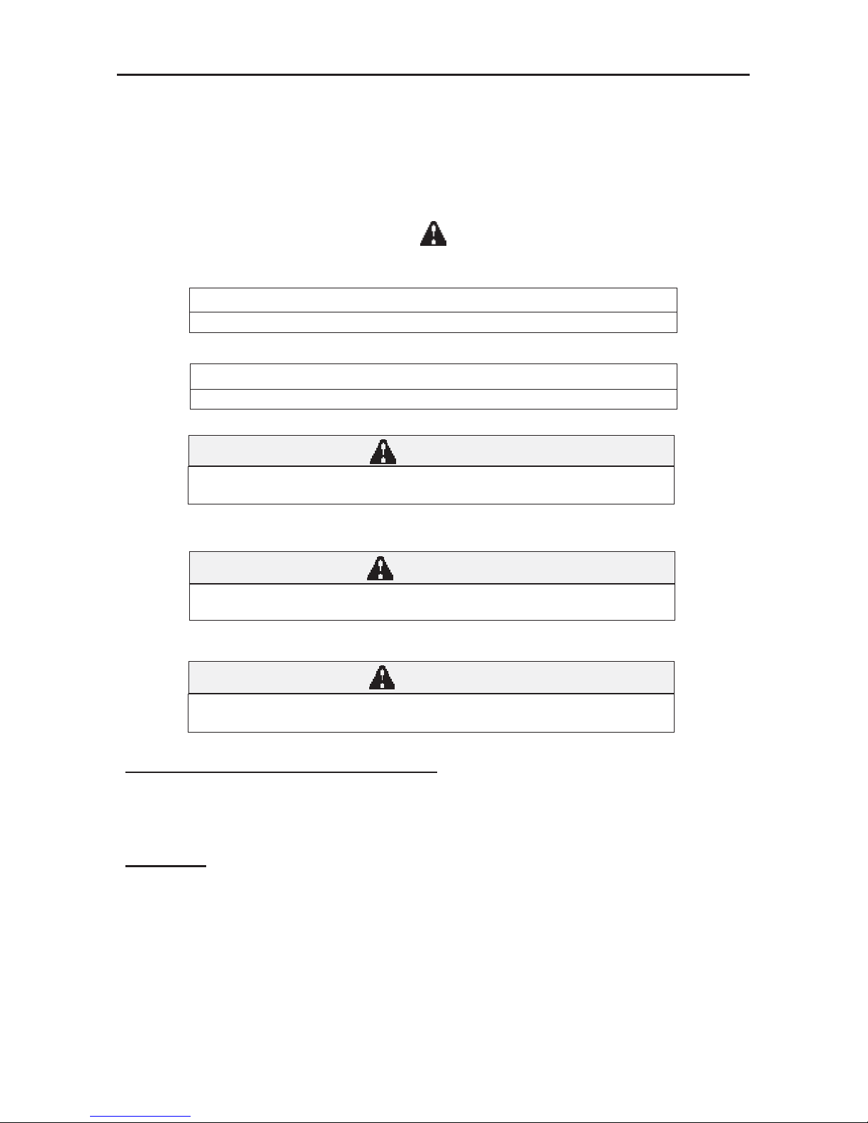
SAFETY ALERT SYMBOL
Also, observe
NOTE or NOTICE
Provides information, special instructions or references about the lift truck.
IMPORTANT
Precautions which must be taken to avoid damage to the lift truck.
CAUTION
Indicates a potentially hazardous situation which, if not avoided, may result in minor or
moderate injury. May also alert unsafe practices.
WARNING
Indicates a potentially hazardous situation which, if not avoided, may result in death or
serious injury!
DANGER
Indicates an imminently hazardous situation which, if not avoided, will result in death or
serious injury.
CALIFORNIA PROPOSITION 65 WARNING
Diesel Engine Exhaust and some of its constituents are known to the State of California
to cause cancer, birth defects or other reproductive harm.
WARNING: Battery posts, terminals and related accesories and related accessories
contain lead and lead compounds. Wash hands after handling.
IX
Page 14
SAFETY DECALS
The purpose of this chapter is to introduce you to the safety messages, decals, and nameplates found on
your forklift truck. The decals are identified by name, part number, location, and a brief description. (The
forklift model logos, and other misc. decals not shown, can be found in your forklift parts manual.) The
decals illustrated may not be exactly the same as those installed on your forklift; installation of the decals
varies depending on the forklift model, series, decal updates, etc.. The size and location of some decals
limit the amount of information that can be placed upon it. For this reason, additional detailed information
not found on the decals is provided through-out this manual.
Every decal placed on the lift truck is important; they are constant reminders of safety and instructions that
should never be taken for granted. Even experienced operators can be seriously injured or killed by ignoring, refusing to enforce, or forgetting to follow safe operating procedures! Do not assume you know all safety issues concerning the decals. Before operating the lift truck; learn the meaning(s) of the decals as
described in this manual. If any decal becomes illegible or missing, have it replaced immediately! Always
replace decals using the same decal part no., unless otherwise specified by the manufacturer. For replacement decals not found in your parts manual, contact your nearest dealer. If you have any questions, contact
your supervisor or nearest dealer for advice before operating your forklift!
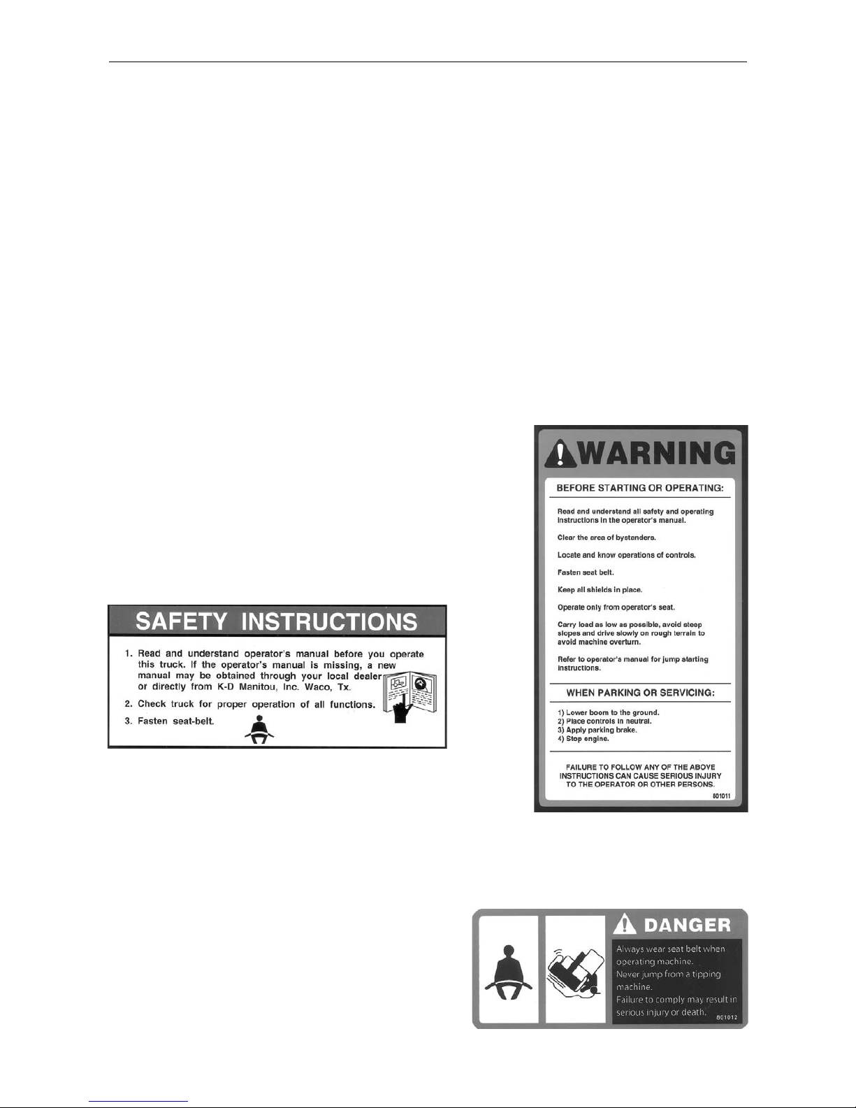
Before Starting - 801011
(Boom equipped models). Location: on the brake fluid cover panel (to
the left and below the dash panel).
Safety Instructions - 420792
(Mast equipped models). Location: on or near the operator manual
storage case, and/or on the dash panel.
Instructions for the forklift operator; before operating the forklift.
Use of Seat Belt - 801012
(Boom equipped models). Location: to the right of the
operator, near the hydraulic control lever.
Instructs the operator to always wear the seat belt during
operations, and never jump from an over-turning forklift.
X
801011
Page 15
SAFETY DECALS
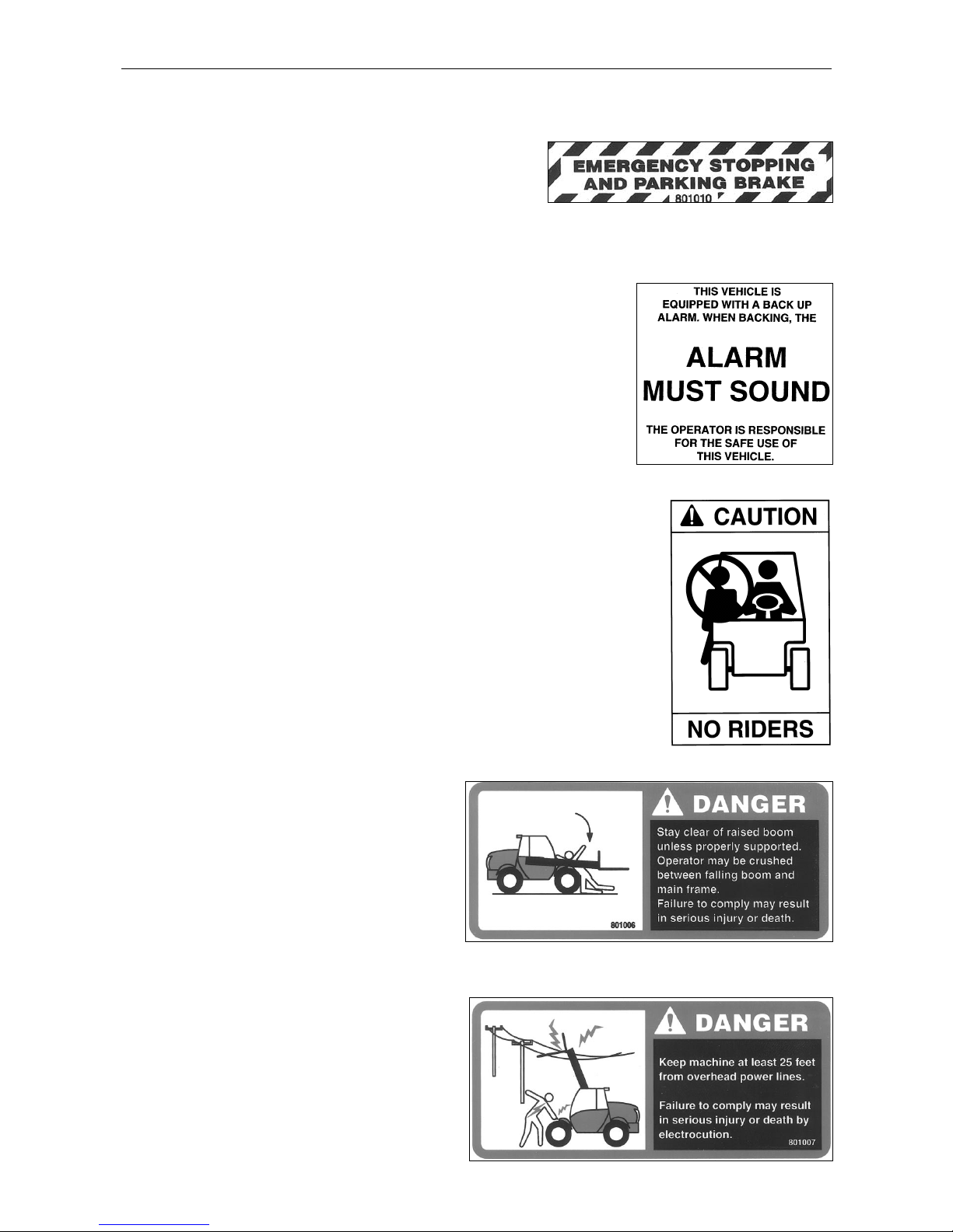
Emergency and Parking Brake - 801010
Location: near the park brake lever.
Identifies the Emergency/Parking Brake Lever.
Alarm Must Sound - 496162
Location: on the dash, in direct view of the operator.
The backup alarm must sound when the forklift is placed in reverse gear.
No Riders - 420732
Location: on the cab entrance(s), and on or near wheel fenders and engine
cover.
Informs: riders are not allowed on the forklift.
Clear of Raised Boom - 801006
(Boom equipped models). Location: on both sides
of the boom nose.
Keep away from unsupported boom.
Clear of Power Lines - 801007
(Boom equipped models). Location: on both sides
of the boom nose.
Keep away from power lines.
XI
Page 16
SAFETY DECALS
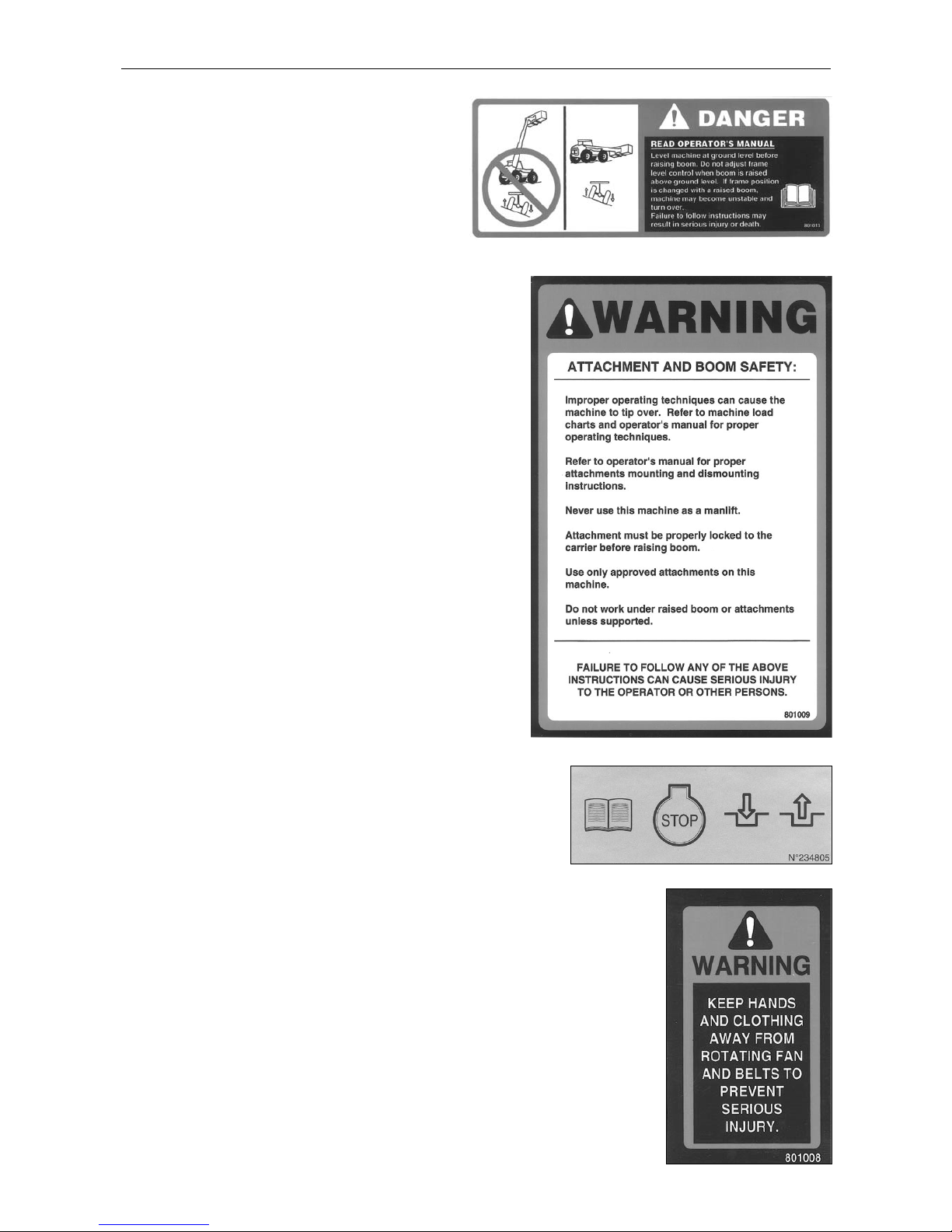
Use of Frame Leveling - 801013
(Boom equipped models). Location: to the right of
the operator near the hydraulic control lever.
Frame leveling notice; load must be lowered.
Attachment and Boom Safety - 801009
(Boom equipped models). Location: on both sides of the
boom nose.
Important reminders of attachment and boom safety.
Hydraulic Coupling - 234805
Location: near the quick-disconnect adapters.
Stop the engine and release hydraulic pressure before changing
attachments.
Rotating Fan and Belt(s) - 801008
Location: on the radiator near the fan, and on any fan belt/pulley cover(s).
Keep hands and clothing away from rotating fan and belts.
XII
Page 17
SAFETY DECALS
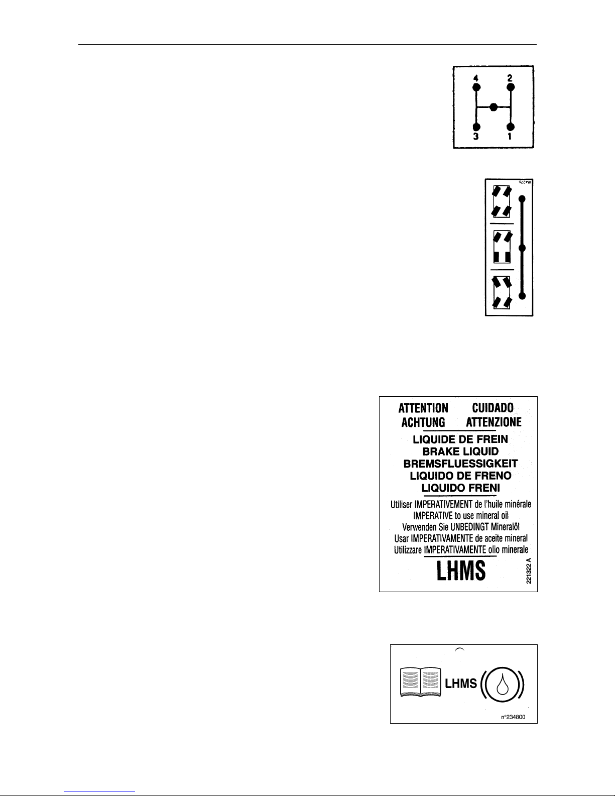
Gear Shift Pattern - 33460
(4-speed transmission models). Location: near the gear shift lever.
Identifies the gear shift pattern of the forklift transmission.
Steering Mode - 184276
(4 wheel steer equipped models). Location: near the steering mode selection lever.
Identifies the steering mode selection.
Mineral Oil (Brake Reservoir) - 221322 or 234800
Location: attached to the brake fluid reservoir.
Refer to the Operator/Service Manual for the correct brake fluid
(mineral oil) to be used in the brake system.
XIII
221322
234800
Page 18
SAFETY DECALS
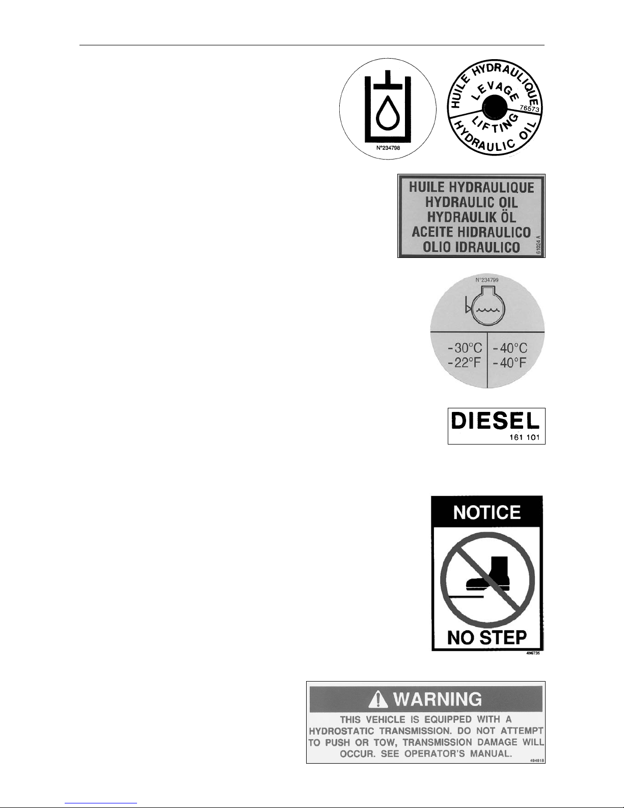
Hydraulic Oil - 234798 or 76573
Location: on the hydraulic tank or filler cap.
Identifies the hydraulic reservoir (tank) or filler cap.
Hydraulic Oil - 61024
Location: on the hydraulic tank.
Identifies the hydraulic reservoir (tank).
Anti-Freeze - 234799
Location: on the radiator, near the radiator filler cap.
Indicates required minimum to maximum anti-freeze protection (-22
0
F to -400F).
Diesel Fuel - 161101
Location: on the fuel tank, near the filler cap.
Identifies the fuel tank, and use of diesel fuel.
No Step - 496735
Location: varies, depending on the forklift model.
Instructs personnel not to use the designated area as a step.
Do Not Tow - 494918
(Hydrostatic equipped models). Location: on the
dash, in view of the operator.
Towing the forklift will damage the transmission;
refer to the operator’s manual.
XIV
Page 19

SAFETY
DECALS
Attachment Warning - 421016
(Boom equipped models). Location: on the boom coupler,
near where the retaining shaft is installed.
Reminder to operator; install attachment retaining shaft and
safety pin before operations.
Hook Here - 24653
Location: at points provided on the forklift, where straps or chains may be attached to
secure the forklift to a trailer during transport.
Fork Safety - 426641
(Mast equipped models). Location: on the front and back side of the mast’s outer rails,
at eye level (4 required).
Instructs personnel not to travel beneath or upon the lift truck forks.
Pinch Point, Large, 2.5 x 4.5 in. - 426643
Pinch Point, Small, 1.5 x 2.75 in. - 426642
(Mast equipped models). Location: on the front and rear sides
of the mast cross bracing.
Keep fingers away from the mast
crossbracing.
HAND THROTTLE DANGER - 804784
(Boom equipped models, option). Location: Near the hand throttle mechanism.
Reminder to operator; set parking brake before operating hand throttle.
Disengage hand throttle before leaving the forklift.
XV
Page 20
SAFETY DECALS
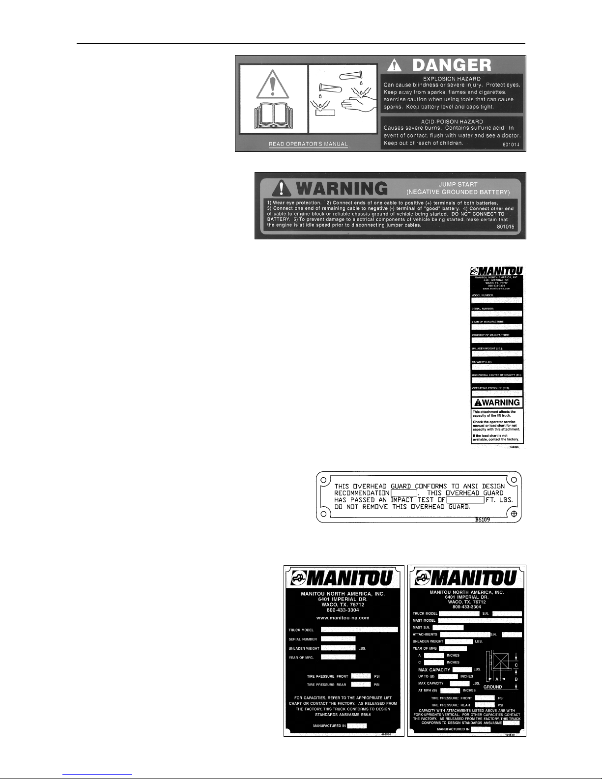
Acid in Battery - 801014
Location: in or near the battery
storage compartment.
Addresses battery hazards.
Jump Start Battery - 801015
Location: in or near the battery storage
compartment.
Jump start instructions.
Attachment Plate - 425995
Location: on the optional removeable forklift attachment.
Important manufacturer information about the attachment. Record this information for use
when contacting the maufacturer for parts and service.
Overhead Guard Data Plate - B6109
Location: attached to the overhead guard.
Overhead guard conformity.
Forklift Data Plate - 496550
(Boom equipped models)
Forklift Data Plate - 496538
(Mast equipped models)
Location: within the operator’s compartment.
Important forklift truck identification. Record
this information for use when contacting the
manufacturer for parts and service.
XVI
496550
496538
Page 21
MRT 1432 - 1635 M
SS
eries
3
MMRRTT
11443355
M
M
Series
Series
Turbo
MMRRTT
11663355
M
M
Series
Series
Turbo
Page 22

4
MRT 1432 - 1635 M
SS
eries
IT
EN
DE
1
st
DATE PUBLICATION
09/2003
Catalogue information:
Date publication:
Text and illustrations herewith enclosed
may not be reproduced, not even in part
and by any means.
Because of the possible time lag beween
the introduction of technical modifications
(an on-going process the aim of which
is to offer products which are being
continually improved) and the latest up
date of the manual, we must point out,
for the sake of correctness, that the data
contained in this edition is liable to chan-
ge at any time and are therefore not
binding.
1
st
DATUM AUSGABE
09/2003
Katalog auskunft:
Datum ausgarbe:
Die Reproduktion, auch nur teilweise, die-
ses Textes und der Abbidungen ist verboten.
Aus Gründen der Korrektheit muß darauf
hingewiesen werden, daS der
Zeitunterschied zwischen in Druck
befindlicher Naufassung und technischen
Veränderungen (die für ein Angebot von
immer basseren Geräten kontinuierlich
sind) zu Unterscheden in den Angaben
dieser Auflage Fühuren kann und daß die
darin enthaltenen Angaben underbindlinch
sind und jederzeit verändert werden kön-
nen.
1a DATA DI PUBBLICAZIONE
09/2003
Informazioni catalogo:
Data di pubblicazione:
E’ vietata la riproduzione, anche parziale,
del testo e delle illustrazioni.
La differenza tra i tempi di aggiornamento
in stampa e i tempi delle modifiche tecni-
che (variando quast’ultime
continuamente, ciò al fine di offrire prodot-
ti sempre più qualificati) impongono di
dichiarare, per correttezza, che i dati
contenuti nella presente edizione sono
suscettibili di variazione in qualsiasi
momento e che quindi non sono
impegnativi.
Page 23

MRT 1432 - 1635 M
SS
eries
IT
EN
DE
5
TABLE OF CONTENTS
11 -- IINNSSTTRRUUCCTTIIOONNS
S
- Original replacement parts and
attachments.
- Driver’s operating instructions.
- Warning
- General instructions.
- Operating instructions.
- Handling instructions.
- Load handling.
- Maintenance instructions of the lift
truck.
- Before starting up a new lift truck.
22 -- DDEESSCCRRIIPPTTIIOON
N
- Characteristics.
- Dimensions and load charts.
- Instruments and controls.
33 -- MMAAIINNTTEENNAANNCCE
E
- Filters cartridges and belts.
- Lubrificants.
- Servicing schedule.
A - Daily or every 10 hours service.
B - Every 50 hours service.
C - Every 250 hours service.
D - Every 500 hours service.
E - Every 1000 hours service.
F - Every 2000 hours service.
G - Every 5000 hours service.
H - Occasional maintenance.
44 -- SSYYSSTTEEMMS
S
- Electrical system.
- Key to electrical system.
- Electrical system tables.
- Hydraulic system.
- Key to moviment hydraulic system.
- Key to brake/steering hydraulic
system.
- Key to transmission hydraulic
system.
- Maintenance handbook
INHALTSVERZEICHNIS
11 -- AANNWWEEIISSUUNNGGEEN
N
- Ersatzteile und originalausstattung.
- Gebrauchsanweisung für den
fahrer.
- Warnung.
- Allgemeine anweisungen.
- Fahranweisungen.
- Handhabungsanweisungen.
- Handhabung einer last.
- Wartungsanweisungen des
gebelstaplers.
- Vor der inbetriebnahme eines neuen
gabelstaplers.
22 -- BBEESSCCHHRREEIIBBUUNNG
G
- Technische daten.
- Abmessungen und lastdiagramm.
- Steuer- und bedienungsinstrumente.
33 -- WWAARRTTUUNNG
G
- Filterelemente und riemen.
- Schmiermittel.
- Wartungsintervalle.
A -Täglich oder alle 10 Betriebsstunden.
B - Alle 50 Betriebsstunden.
C - Alle 250 Betriebsstunden.
D - Alle 500 Betriebsstunden.
E - Alle 1000 Betriebsstunden.
F - Alle 2000 Betriebsstunden.
G - Alle 5000 Betriebsstunden.
H - Gelegentliche wartung.
44 -- AANNLLAAGGEEN
N
- Elektrische Anlage.
- Legende verbraucher der
elektrischen anlage.
- Tafel der elektrischen anlage.
- Hydraulische Anlage.
- Legende Hydraulikanlage der
bewegungsabläufe.
- Legende hydraulikanlage
bremse/lenkung.
- Legende hydraulikanlage- Antrieb.
- Wartungshandbuch
INDICE
11 -- IISSTTRRUUZZIIOONNI
I
- Ricambi e attrezzature originali.
- Istruzioni d’uso per il carrellista.
- Avvertenze.
- Istruzioni generali.
- Istruzioni di guida.
- Istruzioni di movimentazione.
- Movimentazione di un carico.
- Istruzioni di manutenzione del
carrello elevatore.
- Prima della messa in marcia del
carrello elevatore nuovo.
22 -- DDEESSCCRRIIZZIIOONNE
E
- Caratteristiche.
- Dimensioni e diagramma di
carico.
- Strumenti di controllo e di
comando.
33 -- MMAANNUUTTEENNZZIIOONNE
E
- Elementi filtranti e cinghie.
- Lubrificanti.
- Periodicità’ di manutenzione.
A - Tutti i giorni o ogni 10 ore di marcia.
B - Ogni 50 ore di marcia.
C - Ogni 250 ore di marcia.
D - Ogni 500 ore di marcia.
E - Ogni 1000 ore di marcia.
F - Ogni 2000 ore di marcia.
G - Ogni 5000 ore di marcia.
H - Manutenzione occasionale.
44 -- IIMMPPIIAANNTTI
I
- Impianto elettrico.
- Leggenda impianto elettrico.
- Tavole impianto elettrico.
- Impianto idraulico.
- Schema impianto idraulico dei
movimenti.
- Schema impianto idraulico sterzo e
freni.
- Schema impianto trasmissione
idrostatica.
- Libretto manutenzione
Page 24

6
MRT 1432 - 1635 M
SS
eries
IT
EN
DE
55 -- AADDAAPPTTAABBLLEE AATTTTAACCHH-
-
MMEENNTTSS IINN OOPPTTIIOONN OONN
TTHHEE RRAANNGGE
E
- Introduction.
- General recommendations for use of
a lift truck.
- How to mount the accessory with
manual lock
- How to mount the accessory with
hydraulic lock(optional).
- Technical specifications and load
charts of attachments.
55 -- AALLSS SSOONNDDEERRAAUUSSSSTTAATT-
-
--TTUUNNGG AANNZZUUPPAASSSSEEN
N
DDEESS ZZUUBBEEHHÖÖR
R
- Einleitung.
- Allgemeine hinweise zur verwen
dung eines gebelstaplers.
- Montage des zubehÖrtells mit manueller
verriegelung
- Montage des zubehÖrtells mit hydrauli
scherverriegelung
- Technische daten und tabelle der
tragfähigkeiten des zubehörs.
55 -- AACCCCEESSSSOORRII AADDAATTTTAABBIILLII
IINN OOPPZZIIOONNEE SSUULLLLA
A
GGAAMMMMA
A
- Introduzione.
- Consigli relativi all’utilizzo del
carrello.
- Montaggio dell’accessorio con
bloccaggio manuale.
- Montaggio dell’accessorio con
bloccaggio idraulico (opzional).
- Caratteristiche tecniche accessori e
diagrammi di portata.
Page 25

MRT 1432 - 1635 M
SS
eries
IT
EN
DE
7
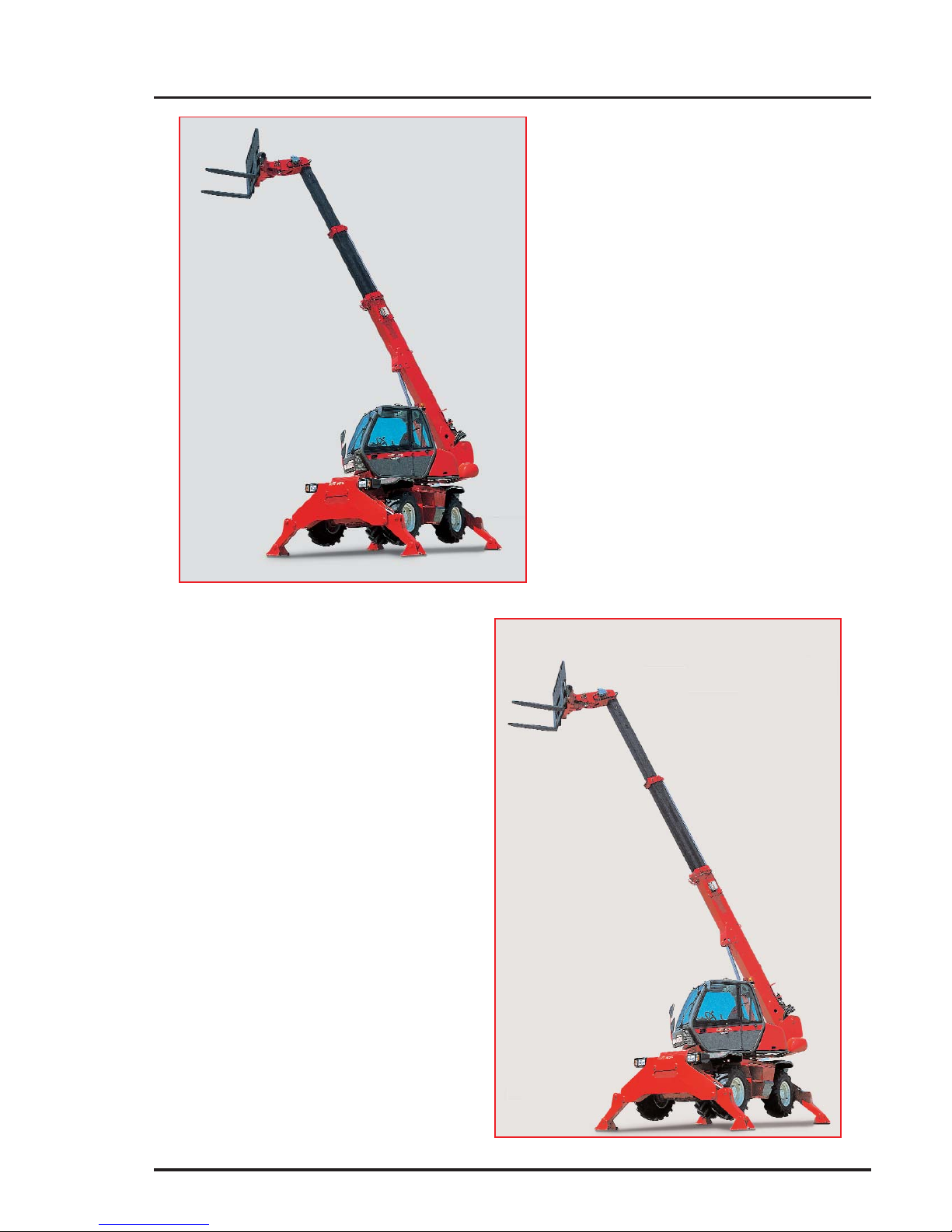
INTRODUCTION
Our telescopic lift rotativ trucks have
been designed to ensure simple
manoeuvres and easy maintenance.
Before operating the truck for the first
time, the driver should read and become
fully familiar with the various chapters in
this manual.
These instructions have been prepared
to provide all the information required for
proper servicing and truck operation. By
complying with these instructions, the
truck driver will be able to get the best
performances from his vehicle.
The terms “right” and “left”, “front” and
“rear” used in this manual refer to positions viewed by the driver seated normally in the driving seat.
Always state the following information
when ordering spare parts or requesting
technical information:
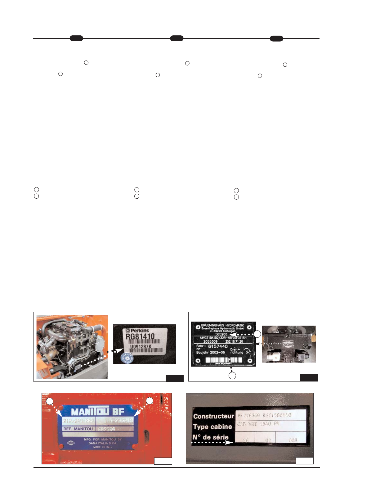
Manufacturer's data plate (FIG.A)
-Model___________________________
-Series__________________________
- Serial N°________________________
- Chassis N°______________________
- Year of manufacture_______________
On internal combustion engine(FIG.B)
- Engine No_______________________
EINFÜHRUNG
Unsere Teleskoplader sind zu dem einzigen Zweck entwickelt worden, dem
Fahrer eine große
Bedienungsfreundlichkeit und dem
Mechaniker ein Höchstmaß an
Wartungsfreundlichkeit zu bieten.
Bevor man jedoch den Teleskoplader
zum ersten Mal in Betrieb nimmt, sollte
der Bediener die in diesem Handbuch
behandelten Argumente aufmerksam
durchlesen und verstehen, denn diese
Betriebsanleitung wurde verfaßt, um
jedes Problem zu lösen, das bei Fahren
oder der Wartung des Teleskopladers
auftauchen kann. Wenn er diese
Anleitungen befolgt, ist der Bediener in
der Lage, die Leistungsmöglichkeiten
seines Teleskopladers aufs Beste
auszunutzen. Die Begriffe “rechts” und
“links”, “vorn” und “hinten” beziehen sich
auf eine Person, die auf dem
Fahrerplatz sitzt und nach vorne schaut.
Wenn Ersatzteile bestellt werden oder
Informationen technischer Art angefordert werden, sind immer die folgenden
Angaben anzuführen:
Typenschild des herstellerrs
(ABB. A)
- Modell__________________________
- Serie___________________________
- Serien-Nr._______________________
- Fahrgestell-Nr.___________________
- Baujahr_________________________
Auf dem dieselmotor (ABB. B)
- Motor-Nr.________________________
INTRODUZIONE
I nostri carrelli elevatori telescopici rotativi sono stati progettati con l’unico
scopo di offrire all’operatore una grande
semplicità di manovra e al meccanico la
massima facilità di manutenzione.
Tuttavia, prima di mettere in funzione il
carrello elevatore per la prima volta, l’operatore deve leggere con attenzione e
capire i vari argomenti trattati in questo
manuale che è stato appunto preparato
per aiutare a risolvere qualunque problema di conduzione e di manutenzione.
Seguendo queste istruzioni, l’operatore
sarà in grado di sfruttare al meglio le
potenzialità del suo carrello elevatore
telescopico.
I riferimenti di “destra” e “sinistra”,
“avanti” e “indietro” si intendono per una
persona che occupa il posto del conduttore del carrello e che guarda di fronte a
se.
Quando si ordinano i pezzi di ricambio o
per tutte le informazioni di carattere tec-
nico, si prega di specificare sempre:
Targhetta del costruttore (FIG.A)
-Modello_________________________
-Serie ___________________________
-N° d iserie_______________________
-N° di telaio______________________
- Anno di fabbricazione
______________
Sul motore termico (FIG.B)
- N° del motore____________________
FIG.A
FIG.A
FIG.A
Page 26
8
MRT 1432 - 1635 M
SS
eries
IT
EN
DE
Auf dem hydrostatishen antrieb
(ABB. C)
- Bezugs-Nr. MANITOU 3___________
- Serien-Nr. 4_____________________
Auf der vorder- und hinterache
(ABB. D)
- Typ und Modell der Achse__________
________________________________
- Serien-Nr. der Vorderachse_________
________________________________
- Serien-Nr. der Hinterachse__________
_____________________________________
1 - Typ und Modell der Achse
2 - Serien-Nr.
In der kabine (ABB. E)
Kabinen-Nr.___________________
Um diese Angaben stets bei der Hand
zu haben, ist es ratsam, die Nummern
Ihres Geräts in den freien Feldern einzutragen. Da die MANITOU-Politik nach
der ständiger Verbesserung unserer
Produkte strebt, kann die Lieferpalette
unserer Teleskoplader einigen Änderungen ausgesetzt werden, deren
Bekanntgabe an die Kundschaft nicht
verpflichtend ist.
On hydrostatic drive (FIG.C)
- MANITOU referenceN° 3____________
- Serial N° 4______________________
On front and rear axle (FIG.D)
- Axle type and model_______________
________________________________
- Serial N° of front axle______________
________________________________
- Serial N° of rear axle______________
_________________________
1 - Axle type and model
2 - Serial N°
On cab (FIG.E)
Cab N°
______________________
Write all these numbers in the empty
spaces. Since the MANITOU policy is to
constantly improve our products, our
range of telescopic lift trucks may be
subject to modifications without our
being obliged to give advance warning
to our customers.
Sulla trasmissione idrostatica (FIG.C)
- N° di riferimento MANITOU 3____________
- N° di serie 4_______________________
Sull’assale anteriore e posteriore
(FIG.D)
- Tipo e modello assale__________________
____________________________________
- N° di serie dell'assale anteriore__________
____________________________________
- N° di serie dell'assale posteriore__________
____________________________________
1 - Tipo e modello dell’assale
2 - Numero di serie
Sulla cabina (FIG.E)
N° della cabina____________________
Per poter indicare più facilmente tutti
questi numeri, consigliamo di riportarli
subito negli spazi vuoti che precedono.
Poiché la politica MANITOU è di tendere
ad un miglioramento costante dei nostri
prodotti, la nostra gamma di carrelli elevatori telescopici può essere soggetta
ad alcune modifiche senza che sussista
l’obbligo per noi di dar avviso alla nostra
clientela.
1
2
FIG.D
FIG.C
FIG.E
3
4
FIG.B
Page 27

Page 28

Page 29

1
1
--IIS
S
T
T
R
R
U
U
Z
ZII
O
O
N
NII
IIN
N
S
S
T
T
R
R
U
U
C
C
T
TII
O
O
N
N
S
S
A
A
N
N
W
W
E
EII
S
S
U
U
N
N
G
G
E
E
N
N
Page 30

Page 31

MRT 1432 - 1635 M
SS
eries
IT
EN
DE
1
1
ORIGINAL REPLACEMENT PARTS
AND ATTACHMENTS
All maintenance on our lift trucks
must be carried out using original
parts.
By allowing non-original parts to be
used, you run the risk:
- Legally, of being liable in the event of
an accident.
- Technically, of causing breakdowns to
occur or of reducing your lift truck's
service life.
Using counterfeit parts or components
not approved by the manufacturer may
put an end to contract warranty terms
and lead the maker to withdraw the lift
truck's certificate of compliance.
By using original parts during
maintenance operations,
you are
legally covering yourself.
- Any user who procures parts from
another quarter does so at his own
risk.
- Any user who modifies his lift truck or
has it modified by a service company,
must consider that a new item of
equipment has been brought onto the
market and therefore takes liability for
it.
- Any user who copies original parts or
has them copied is taking a risk from
the legal viewpoint.
- The certificate of compliance only
binds
the maker for parts chosen or
produced
under the maker's control.
- The practicalities of maintenance terms
are set out by the maker. The maker is
in no way liable in the event of the
user not
complying with such terms.
The manufacturer brings to the
user:
- His know-how and skill.
- Guaranteed quality work.
- Original replacement parts.
- Help with preventive maintenance.
- Effective help with diagnosing faults.
ERSATZTEILE UND ZUBEHÖR
Zur Instandhaltung unsere
Teleskoplader müssen
Originalersatzteile verwendet wer-
den
Die Verwendung nicht orginaler
Ersatzteile beinhaltet gewisse
Risiken
- Im Falle eines Unfalls die rechtlichen
Konsequenzen zu tragen
- Technische Betriebsstörungen
hervorzurufen oder die Lebensdauer
des Gabelstaplers zu verringern.
Die verwendung nicht orginaler
Ersatzteile Teilen oder vom Hersteller
nicht zugelassenen Komponenten führt
zum Erlöschen der vertraglichen
Garantie führen und zwingd den
Hersteller zum Rückzug der
Konformitätserklärung zwingen.
Durch den einsatz von originalteilenbei Instandhaltungsarbeiten,
schützen sie sich rechtlich.
- Der Benutzer, der seine Ersatzteile
anderswo bezieht, tut dies auf eigene
Gefahr
- Der Benutzer, der seinen
Teleskoplader verändert oder durch
einen Dienstleistungsbetrieb verändern
läßt, muß davon ausgehen, daß ein
neues Produkt auf den Markt kommt
und wird somit haftpflichtig.
- Der Benutzer, der Originalteile kopiert
oder kopieren läßt, setzt sich rechtlichen Gefahren aus.
- Die Konformitätserklärung bindet den
Hersteller nur für die von ihm gewählten oder unter seiner Aufsicht agefertigten Ersatzteile Teile.
- Die praktischen Wartungsbedingungen
werden vom Hersteller definiert. Sollte
der Benutzer diese nicht einhalten,
übernimmt der Hersteller keine
Haftung.
Der Hersteller bietet dem Benutzer:
- Sein Know-how und seine Kompetenz.
- Eine Qualitätsgarantie der
durchgeführten Arbeiten.
- Original Ersatzteile.
- Hilfestellungen zur vorbeugenden
Wartung.
- Eine wirkungsvolle Diagnosehilfe.
RICAMBI E ATTREZZATURE ORIGINALI
La manutenzione dei nostri carrelli
elevatori deve tassativamente esse-
re realizzata con pezzi originali.
Autorizzando l’utilizzo di pezzi non
originali, rischiate:
- Giuridicamente di coinvolgere la
vostra responsabilità in caso
d’incidente.
- Tecnicamente di causare problemi di
funzionamento alla longevità del
carrello elevatore.
L’utilizzo - da parte dell’utente - di pezzi
contraffatti o di componenti non omolo-
gati può mettere un termine alle condi-
zioni di garanzia contrattuale e indurre il
costruttore al ritiro del Certificato di
Conformità.
Utilizzando i pezzi originali durante
le operazioni di manutenzione, vi
proteggete giuridicamente.
- L’utente che si rifornisce altrove, lo fa a
suo rischio e pericolo.
- L’utente che modifica o fa modificare
da terzi il carrello elevatore, deve
essere consapevole che un nuovo
materiale è messo sul mercato, il che
coinvolge la sua responsabilità.
- L’utente che copia o fa copiare i pezzi
d’origine, si espone a rischi giuridici.
- Il Certificato di Conformità implica la
responsabilità del fabbricante solo per i
pezzi scelti o elaborati sotto il suo controllo.
- Le condizioni pratiche di manutenzione
sono fissate dal fabbricante. Se l’utente non le rispetta, la responsabilità del
fabbricante non è coinvolta.
Il fabbricante apporta all’utente:
- Il savoir-faire e la sua competenza.
- La garanzia della qualità dei lavori
realizzati.
- I pezzi di ricambio originali.
- Un’assistenza alla manutenzione
preventiva.
- Un’efficace assistenza alla diagnosi.
Page 32

2
1
MRT 1432 - 1635 M
SS
eries
IT
- Enhancements gained from feedback.
- Training for operating staff.
- Only the manufacturer knows the
details of the lift truck design and the
refore has the best technological capa
bility to carry out maintenance.
Original replacement parts are
distributed exclusively
by MANITOU and its dealer
network.
You can obtain the list of dealers by
phoning the spare parts department on :
TEL : 0033240091011
- Ständige Weiterentwicklung der
Produkte.
- Eine Ausbildung des
Betriebspersonals.
- Nur der Hersteller kennt die
Konstruktion
des Teleskopladers im Detail und
verfügt somit über die besten techni
schen Fähigkeiten, um dessen
Wartung zu gewährleisten.
Originalersatzteile werden aussch-
ließlich von MANITOU und dem
netz seiner Vertragshändler
vertrieben.
Ein Anruf bei unserer Ersatzteilabteilung
genügt und Sie erhalten die Liste der
Vertragshändler :
TEL : 0033240091011
EN
DE
- I miglioramenti dovuti allo scambio di
esperienze.
- La formazione del personale
incaricato.
- Solo il fabbricante conosce
dettagliatamente la progettazione del
carrello e quindi le migliori capacità
tecnologiche per assicurarne la
manutenzione.
I pezzi di ricambio d’origine sono
distribuiti esclusivamente da
MANITOU
e dalla rete dei concessionari.
La lista della rete dei concessionari può
esservi fornita telefonando al servizio
dei pezzi di ricambio :
TEL : 059950518
Page 33

DRIVER’S OPERATING INSTRUCTION
Caution
Whenever you see this symbol it
means :
Warning! Be careful! Your safety or
the safety of the lift truck is at risk.
- Most accidents connected with the
use, maintenance and repair of the lift
truck are due to non application of the
basic safety instructions. By being
aware of the risks to which you are
exposed and by taking the necessary
preventive measures, you should be
able to avoid accidents occurring.
- Any operation or manoeuvre not
described in the instructions is prohibited, however, any person who does
use another method must first ensure
that he is not putting himself, another
person or the lift truck in danger.
- The manufacturer is not able to anticipate all possible risk situations.
Therefore the safety instructions and
notices given in the user manual and
on the lift truck are not exhaustive.
Any bending of the rules in safety noti-
ces or the user, maintenance or repair
instructions for your lift truck may result
in serious, or even fatal, accidents.
We would remind users of the risks in
driving at excessive speed with regard
to traffic conditions, particularly :
- Risk of loss of control on a poor-qua
lity track.
- Increased stopping distance.
BEDIENUNGSANLEITUNG FÜR
DEN FAHRER
Warnung
Dieses Symbol bedeutet:
Achtung! Seien Sie vorsichtig! Ihre
Sicherheit, die Sicherheit Dritter
oder die des Teleskopladers sind in
Gefahr.
- Die meisten Unfälle beim Gebrauch,
bei der Wartung und bei der Reparatur
des Gabelstaplers sind auf die
Nichtanwendung und Nichteinhaltung
der grundlegenden
Sicherheitsanweisungen zurückzuführen. Wenn Sie diese Gefahren erkennen, und die nötigen vorbeugenden
Maßnahmen treffen, können Sie diese
Unfälle vermeiden.
- Jegliche Anwendung, jedes Manöver,
welches in den Bedienungsanleitung
nicht beschrieben sind, sind von vorn
zu unterlassen.
- Der Hersteller haftet auf keinen Fall für
alle Gefahrensituationen. Die
Anweisungen und
Sicherheitsvorschriften in diesem
Handbuch und auf dem Teleskoplader
selbst erheben daher keinen Anspruch
auf Vollständigkeit.
Alle Verstöße gegen die
Sicherheitsvorschriften, Bedienungs-,
Wartungs- oder Reparaturanweisungen
Ihres Gabelstaplers können schwere, ja
sogar tödliche Unfälle verursachen.
Beachten Sie die Gefahren, welche
durch nicht angepasste
Geschwindigkeit, den
Verkehrsbedingungen,
Witterungsbedingungen und
Fahrbahnbeschaffenheit entstehen:
-Es besteht die Gefahr, in Abhängigkeit
von Geschwindigkeit, Witterung und
Fahrbahnbeschaffenheit die Kontrolle
uber das Fahrzeug zu verlieren
-Der Bremsweg kann sich erheblich
verlängern.
MRT 1432 - 1635 M
SS
eries
IT
EN
DE
1
3
ISTRUZIONI D’USO PER
IL CARRELLISTA
Avvertenza
Ricordate che questo simbolo
significa:
Attenzione! Prudenza! Sono in
gioco la vostra sicurezza e quella
del carrello elevatore.
- La maggior parte degli incidenti legati
all’utilizzo, alla manutenzione e alla
riparazione del carrello elevatore, sono
dovuti alla non-applicazione e all’inosservanza delle più elementari norme di
sicurezza. Individuando i rischi ai quali
vi esponete e prendendo tutte le
necessarie precauzioni, potrete evitare
questi incidenti.
- Tutte le operazioni o manovre non
descritte nel manuale d’istruzioni devono essere evitate, e in ogni caso colui
che utilizza un altro metodo deve
prima assicurarsi che sia garantita la
propria incolumità, quella degli altri e il
buono stato del carrello elevatore.
- Pertanto, non potendo prevedere tutte
le situazioni di pericolo, le istruzioni e
norme di sicurezza relative al carrello
elevatore, date dal costruttore e riportate nel presente manuale, non sono
da considerarsi esaustive.
L’inosservanza delle norme di sicurezza
o delle istruzioni d’uso, di manutenzione
o di riparazione del carrello elevatore
possono essere all’origine di gravi infor-
tuni, anche mortali.
Richiamiamo l’attenzione degli utilizzato-
ri sui rischi a cui vanno incontro, andan-
do ad una velocità eccessiva rispetto
alle condizioni di circolazione, in
particolare:
- Rischio di perdere il controllo su stra
da dissestata.
- Aumento dello spazio di frenata.
Page 34

4
1
MRT 1432 - 1635 M
SS
eries
IT
The user must remain in full control of
his lift truck and should :
- Adapt his speed to each situation in
order to be maintain his own safety,
that of others and of his equipment.
- Always be aware of his stopping
distance.
On the basis of experience, there are a
number of possible situations in which
operating the lift truck is contra-indicated. Such foreseeable abnormal uses,
the main ones being listed below, are
strictly forbidden.
- The foreseeable abnormal behaviour
resulting from ordinary neglect, but
does not result from any wish to put
the machinery to any improper use.
- The reflex reactions of a person in the
event of a malfunction, incident, fault,
etc. during operation of the lift truck.
- Behaviour resulting from application of
the "principle of least action" when
performing a task.
- For certain machines, the foreseeable
behaviour of such persons as :
apprentices, teenagers, handicapped
persons and trainees tempted to drive
a lift truck. Truck drivers tempted to
operate a truck to win a bet, in
competition or for their own personal
experience.
The person in charge of the equipment
must take these criteria into account
when assessing whether or not a per-
son will make a suitable driver.
- Get to know the telescopic fork lift
truck on the terrain where it is to be
used.
- Transport the load with the boom
lowered and fully retracted
- Position the forks at right-angles to the
load to be lifted.
- Drive the truck at a speed appropriate
to conditions and the state of the
ground.
- Never go too fast or brake sharply with
a load.
- When picking up a load, check that the
ground is as even as possible.
Der Benutzer muß das Fahrzeug stän-
dig unter Kontrolle haben :
- Die Geschwindigkeit der Situation
anpassen, um die eigene Sicherheit,
die Sicherheit Dritter und die des
Teleskopladers zu bewahren.
- Den Bremsweg ständig einschätzen
können.
Erfahrungsgemäß können bestimmte
Gegenanzeigen für den Einsatz des
Gabelstaplers auftreten. Diese vorherseh-
baren, unnormalen Einsätze, von denen
die hauptsächlichen nachstehend genannt
werden, sind strengstens untersagt.
-Das vorhersehbare. unnormale
Verhalten aufgrund einer gewòhnlichen
Fahrlàssigkeit. dasjedoch nicht auf
dem Willen eines falschen
Materialeinsatzes beru ht.
-Das Reflexverhalten einer Person bei
einer Funklionsstòrung. einem
Zwischenfall. einer Stòrung. usw. wàh
rend der Benutzung des Gabelstaplers.
-Das Verhalten. das auf der Anwendung
des "Wegs des geringsten
Widerstands" wàhrend der AusfOhrung
einer Arbeit beruht.
-Bei manchen Maschinen das voraus
sehbare Verhalten mancher Personen.
wie z. B.: lehrlinge. Jugendliche.
Behinderte. Praktikanten. die versucht
sind. einen Gabelstapler zu fahren.
Gabelstaplerfahrer. die versucht sind.
den Gabelstapler fOr Wetten.
Wettbewerbe oder fOr ihre eigene
Erfahrung einzusetzen.
Der verantwortliche Mitarbeiter muß
diese Kriterien bei der Bewertung der
Fahrtüchtigkeit einer Person berücksi-
chtigen.
- Machen Sie sich vor jedem Einsatz mit
dem Teleskoplader und den
Geländegegebenheiten vertraut...
- Transportieren Sie die Last in niedriger
Stellung und mit ganz eingefahrenem
Teleskoparm .
- Positionieren Sie die Gabelzinken waa
gerecht zu der anzuhebenden Last.
- Fahren Sie den Gabelstapler mit einer
den Bedingungen und dem Zustand
des Untergrunds angepaßten
Geschwindigkeit.
- Vermeiden Sie beim Fahren mit Last
zu hohe Geschwindigkeit und abrupte
Bremsmanöver.
- Vergewissern Sie sich vor dem
Aufnehmen einer Last, daßder
Untergrund ausreichen tragfähig und
eben ist
EN
DE
L'utilizzatore deve sempre poter control-
lare il carrello elevatore e
quindi deve :
- Adattare la velocità ad ogni situazione
per preservare la propria incolumità,
quella altrui e quella della propria
macchina.
- Valutare continuamente lo spazio di
frenata.
L’esperienza ci insegna che si possono
avere alcune controindicazioni sull’im-
piego del carrello elevatore. Questi
impieghi anomali prevedibili, di cui i prin-
cipali sono elencati qui di seguito, sono
formalmente vietati.
- Il comportamento anomalo prevedibi-
le, che risulta da una negligenza ordinaria, ma che non risulta dalla volontà
di fare un cattivo uso della macchina.
- Il comportamento riflesso di una per-
sona in caso di cattivo funzionamento,
d’incidente, di anomalia, ecc. durante
l’utilizzo del carrello elevatore.
- Il comportamento risultante dall’appli-
cazione della “legge del minimo
sforzo” durante l’esecuzione di un
compito.
- Per alcune macchine, il comportamen-
to prevedibile di certe categorie di persone, quali: apprendisti, adolescenti,
portatori di handicap, personale in
formazione.
I carrellisti tentati di utilizzare il carrello
elevatore per scommesse, competizioni
o per esperienza personale.
Il responsabile dello stabilimento deve
tenere conto di questi criteri per valuta-
re l’attitudine alla guida di una persona.
- Prendere confidenza con il carrello
elevatore telescopico sul terreno dove
sarà utilizzato.
- Trasportare il carico in posizione bassa
e il braccio telescopico rientrato al
massimo .
- Posizionare le forche
perpendicolarmente al carico da
sollevare.
- Guidare il carrello ad una velocità
adeguata alle condizioni e allo stato
del terreno.
- Non andare mai troppo forte né frenare
bruscamente con un carico .
- Al momento di prendere un carico,
verificare che il terreno sia il più
uniforme possibile .
Page 35

- Never attempt to carry out operations
which exceed the lift truck’s capabili
ties.
- Never raise a load in excess of the
lift truck’s capacity and never increase
the size of the ballast.
- Drive around obstacles.
- Take care over electrical wires, tren
ches and recently-excavated or filled
ground.
- Never leave the engine running
unattended.
- Use the parking brake when depositing
difficult loads or on sloping ground.
- Never leave the truck parked with a
raised load.
- Never authorise anyone to approach
or pass below a load.
- Always think of safety and only tran
sport
well balanced loads.
- Never lift a load using one fork only.
- Drive with care and with reflexes alert.
- When the lift truck is not in use, lower
the forks to the ground and engage the
parking brake.
- Never leave the ignition key in the
truck unattended.
- Never leave the truck loaded on a
gradient of over 15% even with the
parking brake engaged.
- When lifting a load, take care that
nothing and no-one interferes with the
movement and adopt proper handling
procedures only.
- Comply with the data provided in the
load diagrams.
- Never transport another person on the
lift truck.
Whenever an implement is changed, to
prevent damage to the hydraulic unions
always proceed as follows:
- Stop the engine
- wait 1 minute for the circuit to
depressurise
Moreover check that the unions are
clean.
- Ensure that the coupling faces are
clean.
- Achten Sie auf die ordnungsgemäße
Verwendung der Steuer - und
Bedieneinrichtungen.
- Versuchen Sie keinesfalls, Arbeiten
durchzuführen, die die Tragfähigkeit
des Teleskopladers überschreiten.
- Heben Sie keinesfalls eine Last an, die
die Tragfähigkeit des Gabelstaplers
übersteigt und erhöhen Sie keinesfalls
das Ausmaß des Kontergewichtes.
- Fahren Sie um Hindernisse herum.
- Achten Sie auf
Stromkabel,Freileitungen, Gräben,
Frisch ausgehobene oder ange
schüttete Böden.
Den Motor in Abwesenheit des Fahres
abstellen.
-Benutzen Sie die Feststellbremse zum
absetzen der Last oder bei Gefälle.
- Den Teleskoplader niemals mit angeho
bener Last abstellen.
Achten Sie darauf, daß sich keine
Personen im Gefahrenbereich der
Maschine oder der Last befinden.
-Aus Sicherheitsgründen, ermitteln Sie
immer den Lastschwerpunkt der
Ladung vor dem Anheben oder dem
Transport.
-Fahren Sie immer mit angepasster
Geschwindigkeit, erhöhter
Aufmerksamkeit und der nötigen
Vorsicht.
-Nach dem Abstellen des
Teleskopladers, ziehen Sie die
Feststellbremse an und senken Sie die
Gabelzinken auf den Boden ab.
- Beachten Sie die in den
Traglastdiagrammen angegebenen
Daten.
- Transportieren Sie niemals weitere
Personen auf dem Gabelstapler.
Jedesmal wenn ein Anbaugerät
ausgewechselt werden soll, beachten
Sie folgende Punkte, um Schäden an
den Hydraulikanschlüssen zu
vermeiden:
- Lassen Sie den Druck ab, indem Sie
den
Verteilerhebel betätigen.
- Vergewissern Sie sich stets, daß diese
Anschlüsse sauber sind.
- Non tentare di compiere operazioni
che superino le capacità del carrello
elevatore.
- Non sollevare un carico superiore alla
capacità del carrello elevatore e non
aumentare la dimensione del
contrappeso.
- Girare intorno agli ostacoli.
- Fare attenzione ai cavi elettrici, ai
fossi, ai terreni scavati da poco o
riportati.
- Non lasciare mai il motore acceso in
assenza del guidatore.
- Utilizzare il freno di stazionamento per
deporre un carico difficile o su un
terreno in pendenza.
- Non lasciare in nessun caso il carrello
in parcheggio con un carico sollevato.
- Non autorizzare nessuno ad avvicinar
si o a passare sotto un carico.
- Pensare sempre alla sicurezza e
trasportare solamente dei carichi ben
equilibrati.
- Non sollevare mai un carico utilizzan
do solamente una forca.
- Guidare con prudenza e prontezza di
riflessi.
- Quando il carrello elevatore non viene
utilizzato, abbassare al suolo le forche
e inserire il freno di stazionamento.
- Non lasciare mai la chiave
d'avviamento sul carrello in assenza
del guidatore.
- Non lasciare il carrello carico su una
pendenza superiore al 15% anche con
il freno di stazionamento inserito.
- Quando si effettua il sollevamento di
un carico, fare attenzione che nulla o
nessuno intralci il movimento ed evita
re di effettuare false manovre.
- Attenersi ai dati indicati sui diagrammi
di carico.
- Non trasportare mai un’altra persona
sul carrello elevatore.
Ogni volta che si cambia un attrezzo,
per evitare di danneggiare i raccordi
idraulici occorre:
- arrestare il motore termico
- aspettare circa 1 minuto per togliere la
pressione del circuito
Inoltre controllare la pulizia di questi
raccordi.
MRT 1432 - 1635 M
SS
eries
IT
EN
DE
1
5
Page 36

6
1
MRT 1432 - 1635 M
SS
eries
IT
GENERAL INSTRUCTIONS
A - Driver’s operating instructions.
- Read the operator's manual carefully,
making sure you understand it.
- The operator’s manual must always be
kept in the lift truck, in the place provided and in the language understood by
the operator.
- Respect the safety notices and instructions given on the lift truck.
- It is compulsory to replace all plates or
stickers which are no longer legible or
which have become worn or damaged.
B - Authorisation to operate (Or
refer to the legislation for each
particular country).
- Only qualified personnel may use the
lift truck. Its use is subject to authorisation to operate being given by the
appropriate manager in the user establishment.
- The user should always carry this
authorisation to operate with him while
he is using the lift truck.
- The driver is not competent to authori
se the driving of the lift truck by
another person.
- In addition, the vehicle should be used
in accordance with good practice for
the profession.
C - Maintenance.
- The user must immediately advise his
superior if his lift truck is not in good
working order or does not comply with
the safety notice.
- The operator is prohibited from
carrying out any repairs or adjustments
himself, unless he has been trained for
this purpose. He must keep the lift
truck properly cleaned if this is among
his responsibilities.
- Carry out daily maintenance (See
chapter : A - DAILY OR EVERY 10
HOURS SERVICE in paragraph : 3 MAINTENANCE).
- Ensure tyres are adapted to the nature
of the ground (See area of the contact
surface of the tyres in the chapter :
CHARACTERISTICS in paragraph : 2 DESCRIPTION).
ALLEGEMEINE ANWEISUNGEN
A - Bedienungsanleitung.
- Die Bedienungsanleitung sorgfältig
lesen und sicherstellen,daßdie Inhalte
und Vorgehensweisen verstanden wurden..
- Die Bedienungsanleitung muß sich
ständig an der dafür vorgesehenen
Stelle im Teleskoplader befinden und in
der vom Fahrer gesprochenen Sprache
sein.
- Die Sicherheitsvorschriften und die auf
dem Gabelstapler beschriebenen
Anweisungen beachten.
- Unbedingt alle Beschriftungen oder
Aufkleber ersetzen, welche verschlissen, unleserlich oder.
B - Fahrerlaubnis
Siehe die entsprechende
Gesetz-
gebung des jeweiligen Landes.
- Nur qualifiziertes und ausgebildetes
Personal darf den Teleskoplader benutzen. Die Benutzung unterliegt zwangsläufig den Regularien des Betreibers
oder dessen Beauftragten.
- Während der Arbeitszeit muß der
Benutzer die Fahrerlaubnis ständig bei
sich tragen.
- Der Fahrer ist nicht dazu befugt, das
Führen des Gabelstaplers durch eine
weitere Person zu erlauben.
- Desweiteren unterliegt die Benutzung
denRegeln dieses Berufszweigs.
C - Instandhaltung.
- Sollte der Benutzer feststellen, daß der
Gabelstapler sich nicht in betriebsbereitem Zustand befindet oder nicht den
Sicherheitsvorschriften entspricht, muß
er dies sofort seinem Vorgesetzten mitteilen.
- Es ist dem Fahrer untersagt, selbst
Reparaturen oder Einstellungen vorzunehmen, es sei denn er wurde hierzu
ausgebildet. Wenn ihm dies übertragen
wurde, muß er seinen Gabelstapler
selbst in einem einwandfreien
Betriebsicheren Zustand halten.
- Durchführung der täglichen
Wartungsarbeiten: (Siehe Kapitel : A TÄGLICH ODER ALLE 10 BETRIEBSSTUNDEN, Abschnitt : 3 - WARTUNG).
- Überzeugen Sie sich, daß die Reifen
für die Bodenart geeignet sind (Siehe
TECHNISCHE DATEN, Abschnitt : 2 BESCHREIBUNG).
ISTRUZIONI GENERALI
A - Manuale d’istruzione.
- Leggere con attenzione e comprendere il manuale d'istruzioni.
- Il manuale d'istruzione deve sempre
trovarsi al suo posto nel carrello elevatore ed essere nella lingua parlata dal
carrellista.
- Osservare le norme di sicurezza e le
istruzioni descritte per il carrello
elevatore.
- Sostituire imperativamente tutte le
targhette o gli adesivi diventati illeggibi
li o deteriorati.
B - Autorizzazione di guida
(Attenersi alla legislazione in
vigore nel paese d’utilizzo).
- Solo il personale qualificato ed appositamente addestrato può utilizzare il
carrello elevatore. Il suo utilizzo è
obbligatoriamente sottoposto all'autorizzazione di guida rilasciata dal
responsabile dello stabilimento dove la
macchina viene utilizzata.
- Si consiglia all'utilizzatore di avere
sempre con sé durante il servizio
l'autorizzazione di guida.
- Il conduttore non può autorizzare la
guida del carrello elevatore ad una
altra persona.
- L'utilizzo deve essere inoltre conforme
alle regole dell'arte della professione.
C - Manutenzione ordinaria.
- L'utilizzatore che constata che il suo
carrello elevatore non funziona bene o
non risponde alle norme di sicurezza,
deve informare immediatamente il
responsabile.
- È vietato al conduttore effettuare lui
stesso qualsiasi riparazione o regolazione a meno che non sia stato formato per tale compito. Dovrà tenere il suo
carrello elevatore in perfetto stato qualora ne sia stato incaricato.
- Effettuare la manutenzione giornaliera
(Vedi capitolo : A - OGNI GIORNO O
OGNI 10 ORE DI FUNZIONAMENTO
nella parte : 3 - MANUTENZIONE).
- Verificare che i pneumatici siano adeguati al tipo di terreno (Vedi superficie
di contatto al suolo dei pneumatici,
capitolo : CARATTERISTICHE nella
parte 2 - DESCRIZIONE)
EN
DE
Page 37

THERE ARE:
• SAND tyres.
• LAND tyres.
• Snow chains.
There are optional solutions, consult
your agent or dealer.
Do not use a worn or damaged tyre
The fitting of foam inflated tyres is prohi-
bited and is not guaranteed by
the manufacturer, excepting prior
authorisation.
- For your own and other people's
safety, it is forbidden to modify the
structure and settings of the various
components of your lift truck yourself
(Hydraulic pressure, relief valve calibration, I.C. engine running speed,
addition of extra equipment etc.). The
same holds with regard to any suppression or modification of the safety
systems, in which case the maker
would no longer be liable.
Regular inspection of your lift truck is
mandatory if it is to be kept in confor-
ming condition. The frequency of such
checks are defined by the current legi-
slation of the country in which the lift
truck
is being operated.
Maintenance or repairs other than those
detailed in part : 3 - (MAINTENANCE)
must be carried out by qualified person-
nel (Consult your agent or dealer) and
under the necessary safety conditions
to maintain the health of the operator
and any third party.
D - Environment.
- A lift truck operating in an area without
fire extinguishing equipment must be
equipped with an individual extinguisher. There are optional solutions, consult your agent or dealer.
- Take into account climatic and atmospheric conditions of the site of utilisation.
ES GIBT:
• SANDREIFEN.
• LANDWIRTSCHAFTSREIFEN.
• Schneeketten.
Es gibt Sonderausstattungen, fragen
Sie Ihren r Vertragshändler.
verschlissenen oder beschädigten Rei-
fen nicht benutzen
Das Aufziehen von mit "geschäumten
Reifen jeglicher Art ist untersagt und wird
nicht vom Hersteller gewährleistet, es sei
denn, er hat eine vorherige Freigabe
erteilt.
- Für Ihre Sicherheit und die Sicherheit
Dritter ist es untersagt, die Struktur und
die Einstellungen der verschiedenen
Komponenten des Teleskoplade selbst
zu verändern (Hydraulikdruck,
Einstellung der Begrenzungsventile,
Motordrehzahl, Hinzufügen von
Zusatzausstattungen, usw.). Das gleiche gilt für die Änderung oder
Entfernung der
Sicherheitsvorrichtungen. In solchen
Fällen ist die Haftung des Herstellers
ausgeschlossen.
Um die Konformität des Teleskopladers
zu gewährleisten, muß dieser
regelmäßig einer Untersuchung unter-
zogen werden, wobei die
Prüfungshäufigkeit von der
Gesetzgebung des jeweiligen
Einsatzlandes des Teleskopladers vor-
gegeben wird.
Die Wartung oder die Reparaturen, die
nicht in Teil : 3 - (WARTUNG) beschrie-
ben sind, müssen von qualifiziertem
Personal durchgeführt werden (wenden
Sie sich an Ihren oder
Vertragshändler). Bei allen
Wartungsarbeiten sind die entsprechen-
den Sicherheitsvorschriften und
Umweltvorschriften des jeweiligen
Einsatzlandes des Teleskoplader zu
beachten
D - Umfeld.
- Sollte der Gabelstapler in einem
Umfeld ohne Löschmittel eingesetzt
werden, muß er mit einem eigenen
Feuerlöscher ausgestattet werden. Es
gibt entsprechende
Sonderausstattungen, fragen Sie Ihren
oder Vertragshändler.
- Klimatische und atmosphärische
Bedingungen des Einsatzortes berücksichtigen
ESISTONO:
• Pneumatici da SABBIA.
• Pneumatici da TERRENO AGRICOLO.
• Catene da neve.
Esistono altre soluzioni opzionali ; per
maggiori informazioni rivolgetevi al
vostro agente o concessionario.
Non usare i pneumatici consumati o
deteriorati
Montare pneumatici gonfiati con schiu-
ma poliuretanica è vietato e non è
garantito dal costruttore, salvo autoriz-
zazione.
- Per la vostra sicurezza e quella altrui,
non modificate voi stessi la struttura o
la regolazione dei vari componenti del
carrello elevatore (Pressione idraulica,
taratura dei limitatori, regime motore,
montaggio di attrezzature supplementari, ecc.). Lo stesso vale per la disattivazione o la modifica dei sistemi di
sicurezza. In questi casi, il costruttore
sarà svincolato da ogni responsabilità.
Per mantenere il carrello elevatore in
“stato di conformità”, è obbligatorio
effettuare controlli periodici. La frequen-
za dei controlli è definita dalla normativa
vigente nel paese d’utilizzo del
carrello elevatore.
Le operazioni di manutenzione o le ripa-
razioni non riportate nella parte : 3 -
(MANUTENZIONE) devono essere
effettuate da personale qualificato (Per
maggiori informazioni, rivolgetevi al
vostro agente o concessionario) e
rispettando le condizioni di sicurezza
atte a garantire la vostra
incolumità e quella altrui.
D - Condizioni ambientali d’uso.
- Dotare il carrello elevatore di un estintore qualora la macchina venga utilizzata in un luogo sprovvisto di mezzi
d'estinzione. Esistono soluzioni opzionali. Per maggiori informazioni, rivolgetevi al vostro agente o concessionario.
- Tenere sempre conto delle condizioni
climatiche ed atmosferiche del luogo di
utilizzo.
MRT 1432 - 1635 M
SS
eries
IT
EN
DE
1
7
Page 38

8
1
MRT 1432 - 1635 M
SS
eries
IT
For operation under average climatic
conditions, i.e. : between -15 °C and
+ 35 °C, correct levels of lubricants in all
the circuits are checked in production.
For operation under more severe clima-
tic conditions, before starting up, it is
necessary to drain all the circuits, then
ensure correct levels of lubricants using
lubricants properly suited to the relevant
ambient temperatures. It is the same for
the cooling liquid.
• Protection against frost (See chapter :
LUBRICANTS AND FUEL in para-
graph : 3 - MAINTENANCE).
• Adaptation of lubricants (Ask your
dealer for information).
• Engine filtration.
• Lighting (Working headlight).
Optional solutions exist, consult your
dealer.
Use of a lift truck is prohibited in protected areas (e.g. refinery, explosive atmo-
sphere). For use in these areas,
specific equipment is available as an
option. Consult your dealer.
If necessary, consult your dealer.
Die Schmiermittel werden im Werk für
durchschnittliche Klimabedingungen ein-
gefüllt, d. h. -15°C bis + 35°C. Für strengere Einsätze muß der Gabelstapler vor
der Inbetriebnahme entleert und mit für
die Umgebungstemperaturen geeigne-
ten Schmiermitteln gefüllt werden. Dies
gilt auch für das Kühlmittel.
• Frostschutz (Siehe Kapitel : SCHMIERMITTEL UND KRAFTSTOFF,
Abschnitt : 3 - WARTUNG).
• Anpassung der Schmiermittel
(Erkundigen Sie sich bei Ihrem oder
Vertragshändler).
• Motorölfilter.
• Beleuchtung (Arbeitsscheinwerfer).
Es gibt Sonderausstattungen, fragen Sie
Ihren oder Vertragshändler.
Der Einsatz des Teleskopladers in EX -
geschützten Räumen ist untersagt (Z.
B. Raffinerie, explosionsgefährdete
Atmosphäre). Für einen Einsätze in sol-
chen Räumen gibt es
Sonderausstattungen. Fragen Sie Ihren
oder Vertragshändler.
Im Zweifelsfall fragen Sie Ihren
oder Vertragshändler.
Il pieno di lubrificanti è già stato effettua-
to in fabbrica, utilizzando lubrificanti per
condizioni climatiche d'uso medie, ossia
da -15°C a + 35°C. Per un utilizzo in
condizioni estreme occorre, prima del-
l'avviamento, svuotare e rifare i pieni,
utilizzando i lubrificanti adatti a tali temperature. Lo stesso vale per il liquido di
raffreddamento.
• Protezione dal gelo (Vedi capitolo :
LUBRIFICANTI E CARBURANTE nella
parte : 3 - MANUTENZIONE).
• Impiego di lubrificanti adeguati (Per
maggiori informazioni rivolgetevi al
vostro agente o Concessionario).
• Filtri motore.
• Luci (Faro di lavoro).
Esistono altre soluzioni opzionali. Per
maggiori informazioni rivolgetevi al
vostro agente o concessionario.
L'utilizzo del carrello elevatore è vietato
negli spazi protetti (Es. : Raffinerie,
atmosfera esplosiva). Per l'utilizzo in
questi spazi, esistono attrezzature
opzionali specifiche. Rivolgetevi al
vostro agente o concessionario.
In caso di necessità rivolgetevi al
vostro agente o concessionario.
EN
DE
Page 39

OPERATING INSTRUCTIONS
A - Driver’s operating instructions.
- Wear clothes suited for driving the lift
truck, avoid loose clothes.
- Never operate the vehicle when hands
or feet are wet or soiled with greasy
substances.
- For increased comfort, adjust the driver’s seat to your requirements and
adopt the correct position in the driver’s cab.
- The operator must always be in his
normal position in the driver’s cab. It is
prohibited to have arms or legs, or
generally any part of the body, protruding from the driver’s cab of the lift
truck.
- Always remember to fasten your seat
belt and adjust it to your requirements.
- The control units must never in any
event be used for any other than their
intended purposes (e.g. climbing onto
or down from the lift truck, portmanteau, etc.).
- If the control components are fitted
with a forced operation (lever lock)
device, it is forbidden to leave the cab
without first putting these controls in
neutral.
- Never allow a passenger to travel on
the lift truck in the driver’s cab.
B - Before starting the lift truck.
- If the lift truck is new, refer to chapter :
BEFORE STARTING UP A NEW LIFT
TRUCK in paragraph : 1 - OPERATING AND SAFETY INSTRUCTIONS.
- Check the condition of the tyres and
the tyre pressures (See chapter : CHARACTERISTICS in paragraph : 2 DESCRIPTION).
- Before starting the lift truck, check the
different levels :
• Engine oil.
• Hydraulic reservoir oil.
• Transmission oil.
• Cooling liquid.
- Also check for possible leakage of oil,
fuel or liquid from the lift truck.
FAHRANWEISUNGEN
A - Sicherheithinweise.
- Zum Führen eines Gabelstaplers geeignete Kleidung tragen, weite Kleidung
vermeiden.
- Niemals mit feuchten oder fettigen
Händen oder Schuhen fahren.
- Für einen besseren Komfort, den
Fahrersitz passend einstellen und eine
sichere Sitzposition im Führerstand
annehmen.
- Es ist verboten, Arme, Beine oder,
generell, irgendein Körperteil über den
Führerstand des Teleskoplader hinausragen zu lassen.
- Immer den Sicherheitsgurt anlegen
und passend einstellen.
- Die Bedienelemente dürfen auf keinen
Fall zu einem anderen als dem
Bestimmungszweck verwendet werden
(Z. B. Auf- und Absteigen vom
Gabelstapler, Kleiderhaken, usw.).
- Sollten die Bedienelemente mit einem
System für erzwungenen Betrieb
ausgestattet sein (Hebelblockierung),
ist es verboten, den Führerstand zu
verlassen, ohne vorher diese
Steuerungen in Neutralstellung zu bringen.
- Niemals Mitfahrer auf dem
Teleskoplader und im Führerstand
zulassen.
B-Vor dem Starten des
Teleskoplader.
- Ist der Teleskoplader neu, siehe
Kapitel : VOR DER INBETRIEBNAHME EINES NEUEN
TELESKOPLADER, Abschnitt : 1 ANWEISUNGEN UND
SICHERHEITSVORSCHRIFTEN.
- Die Reifen auf ihren Zustand und den
Reifendruck prüfen (Siehe Kapitel :
TECHNISCHE DATEN, Abschnitt : 2 BESCHREIBUNG).
- Vor dem Start des Teleskoplader, die
verschiedenen Flüssigkeitsstände
überprüfen :
• Motorölstandprüfen.
• Hydraulikölstand prüfen.
•Getriebeölstand prüfen.
• Kühlmittelstand prüfen.
- Den Teleskoplader ebenfalls auf
Undichtigkeiten von Öl, Kraftstoff bzw.
Flüssigkeit überprüfen.
ISTRUZIONI PER LA GUIDA
A - Disposizioni posto guida.
- Indossare indumenti idonei alla guida
del carrello elevatore, evitando quelli
troppo larghi.
- Non guidare mai con mani o scarpe
umide o sporche di grasso.
- Per un miglior comfort, regolare il
sedile del conduttore e adottare una
buona posizione di guida.
- Il conduttore deve sempre mantenere
la posizione normale di guida. È vietato sporgere braccia e gambe e, in
generale, qualunque parte del corpo,
fuori del posto di guida del carrello elevatore.
- Allacciare e regolare sempre la cintura
di sicurezza.
- Gli organi di comando non devono mai
essere utilizzati per scopi differenti da
quelli a cui sono preposti (Es. : Salire o
scendere dal carrello elevatore, appendere indumenti, ecc.).
- Quando gli strumenti di comando sono
dotati di un dispositivo di marcia forzata (bloccaggio della leva), è vietato
lasciare il posto di comando prima di
rimettere tali comandi in folle.
- Non far salire mai passeggeri sul
carrello elevatore o nel posto di guida.
B - Prima di avviare il carrello
elevatore.
- Se il carrello elevatore è nuovo, riferirsi
al capitolo : PRIMA DI AVVIARE UN
CARRELLO ELEVATORE NUOVO
nella parte : 1 - ISTRUZIONI E
NORME DI SICUREZZA.
- Controllare lo stato e la pressione dei
pneumatici (Vedi capitolo : CARATTERISTICHE nella parte : 2 - DESCRIZIONE).
- Prima dell'avviamento verificare i vari
livelli :
• Olio motore termico.
• Olio serbatoio idraulico.
• Olio trasmissione.
• Liquido di raffreddamento.
- Controllare anche le eventuali perdite
d'olio, di combustibile o di liquido sul
carrello elevatore.
MRT 1432 - 1635 M
SS
eries
IT
EN
DE
1
9
Page 40

10
1
MRT 1432 - 1635
- Check the closing and locking of the
hood.
- Whatever his experience as a truck dri-
ver is, the operator is advised to familiarize himself with the position and
operation of all the controls and instruments before operating the lift truck.
C - Starting the lift truck.
Safety notice.
The lift truck must only be started up or
manoeuvred when the operator is sitting
in the driver’s cab, with his seat belt
adjusted and fastened.
- Never try to start the lift truck by
pushing or towing it.
Such operation may cause severe
damage to the transmission. If neces-
sary, to tow the lift truck in an emer-
gency, the gear-box must be placed in
the neutral position (See chapter : H3 -
in paragraph : 3 - MAINTENANCE).
Instructions
- Make sure that the forward/reverse
lever is in neutral.
- Turn the ignition key to the position I to
activate the electrical system.
- Check the level on the fuel level
gauge.
- Turn the ignition key to position II to
preheat for 15 seconds. (If the
environmental conditions require it)
Do not engage the starter motor for
more than 15 seconds and carry out the
preheating for 10 seconds between
unsuccessful attempts.
- Press the accelerator pedal and turn
the ignition key fully : the I.C. engine
should then start. Release the ignition
key and let the I.C. engine run at idle.
- Before operating in very cold environ
ments wait for the I.C. engine and
hydraulic systems to heat up
adequately.
- Vergewissern Sie sich, daß alle
Zugangsklappen verschlossen und ver
riegelt sind
- Machen Sie sich mit dem
Teleskoplader,der Lage und Funktion
der Bedien- und Steuerelementen vor
Fahrtantritt vertraut.
C - Starten des Teleskoplader.
Sicherheitsvorschriften.
Der Teleskoplader darf erst gestartet
oder bedient werden, wenn der Fahrer
im Führerstand sitzt und den
Sicherheitsgurt eingestellt und angelegt
hat.
- Den Teleskoplader zum Starten nicht
ziehen oder schieben.
Eine solche Bedienung würde schwere
Beschädigungen am Übersetzungsge-
triebe hervorrufen. Sollte das
Abschleppen des Teleskopladers erfor-
derlich sein: (Siehe Kapitel :
H3 -Abschnitt : 3 - WARTUNG).
Anweisungen
- Überzeugen Sie sich davon, daß sich
der Fahrtrichtungswahlschalter in der
Neutralstellung befindet.
- Den Zündschlüssel in Stellung I
drehen, um den elektrischen Kontakt
herzustellen.
- Den Kraftstoffstand auf der Anzeige
überprüfen.
- Den Zündschlüssel in Stellung II
drehen, um ein Vorwärmen von 15
Sekunden zu ermöglichen.
(Wenn die Umgebungsbedingungen es
verlangen)
Den Anlasser nicht länger als 15
Sekunden betätigen, und zwischen
allen erfolglosen Startversuchen ein
Vorwärmen während 10 Sekunden dur-
chführen.
- Das Gaspedal niederdrücken und den
Zündschlüssel bis zum Anschlag
drehen, der Motor muß nun anspringen. Den Zündschlüssel wieder loslassen und den Motor im Leerlauf drehen
lassen.
- Bevor man unter sehr kalten
Klimaverhältnisse arbeitet, abwarten,
dass der Motor und die hydraulischen
Anlagen richtig warm geworden sind.
.
- Accertarsi della corretta chiusura e del
bloccaggio del cofano motore.
- L’utilizzatore, qualunque sia il suo
grado di esperienza come carrellista,
dovrà familiarizzarsi con la posizione e
l'utilizzo di tutti gli strumenti di controllo
e di comando, prima di mettere il carrello elevatore in servizio.
C - Avviamento del carrello
elevatore.
Norme di sicurezza.
Il carrello elevatore può essere avviato
o manovrato solo quando il conduttore
si trova al posto di guida, con la cintura
di sicurezza allacciata e regolata.
- Non trainare o spingere il carrello
elevatore per avviarlo.
Tale manovra potrebbe provocare gravi
deterioramenti alla trasmissione.
Qualora fosse necessario trainare il car-
rello elevatore, mettere il cambio in
posizione neutra(Vedi capitolo : H3 -
nella parte : 3 - MANUTENZIONE).
Istruzioni
- Verificare che la leva dell'invertitore di
marcia sia in folle.
- Ruotare la chiave di avviamento in
posizione I per consentire il contatto
elettrico.
- Controllare il livello del carburante
sull'indicatore.
- Ruotare la chiave di avviamento in
posizione II per permettere il
preriscaldamento e attendere 15
secondi. (Se le condizioni ambientali lo
richiedano)
Non attivare il motorino di avviamento
per più di 15 secondi, e consentire il
preriscaldamento durante 10 secondi
tra tutti i vari tentativi effettuati.
- Premere l'acceleratore e ruotare fino in
fondo la chiave di avviamento, il motore dovrebbe avviarsi. Rilasciare la
chiave di avviamento e lasciare girare
il motore a basso regime.
- Prima di operare in ambienti climatici
molto freddi attendere il corretto
riscaldamento del motore termico e
degli impianti idraulici.
IT
EN
DE
Page 41

MRT 1432 - 1635 M
SS
eries
IT
EN
DE
1
11
- Check all control instruments immediately after starting up, when the I.C.
engine is warm and at regular intervals
during use, so as to quickly detect any
faults and to be able to correct them
without any delay.
- If an instrument does not show the correct display, stop the I.C. engine and
immediately carry out the necessary
operations.
D - Driving the lift truck
Safety notice
- Always drive the lift truck with the forks
or attachment at approximately 300
mm from the ground, i.e. In the transport position.
- Familiarise yourself with the lift truck
on the terrain where it will be used.
- Ensure that the service brakes and the
sound alarm are working properly.
- Drive according to, and at an appropriate speed for, the conditions and
state of the terrain.
- Slow down before executing a turn.
- In all circumstances make sure you are
in control of your speed.
- On damp, slippery or uneven terrain,
drive slowly.
- Brake gently, never abruptly.
- Only use the lift truck’s forward/reverse
lever from a stationary position and
never do so abruptly.
- Always remember that hydraulic type
steering is extremely sensitive to
movement of the steering wheel, so
turn it gently and not jerkily.
- Never leave the I.C. engine on when
the lift truck is unattended.
- Look in the direction you are travelling
and always keep clear visibility of the
road. Use the left and right rear view
mirrors frequently and ensure that they
are kept in good condition, are clean
and correctly adjusted.
- Never use the truck in places poorly
lighted.
- When working at night, ensure that
your lift truck is fitted with full beam
lights. There are optional solutions,
consult your agent or dealer.
- Drive round obstacles.
- Sofort nach dem Anspringen, wenn der
Motor warm ist, und in regelmäßigen
Abständen während des Einsatzes alle
Kontrollinstrumente beobachten, um
eventuelle Anomalien festzustellen
und so schnell wie möglich Abhilfe zu
schaffen.
- Sollte ein Instrument nicht korrekt
anzei
gen, Motor sofort abstellen und die
notwendigen Maßnahmen veranlas-
sen..
D - Fahren des Teleskoplader
Sicherheitshinweise
- Ein Verfahren des Gabelstaplers immer
mit den Gabelzinken oder dem
Anbaugerät ca. 300 mm über dem
Boden, d. h. in Transportstellung, durchführen.
- Machen Sie sich mit der Umgebung,
der Bodenbeschaffenheit und den
Einsatzbedingungen für Ihren
Teleskoplader vertraut.
-Überprüfen Sie vor Fahrtantritt die
Wirksamkeit der Fuß- und Handbremse
- Fahren sie mit angepasster
Geschwindigkeit, und den der Sicht und Bodenverhältnissen gebotenen
Vorsicht.
- Geschwindigkeit vor Kurven herabsetzen herabsetzen.
- Auf feuchtem, rutschigem oder ungleichmäßigem Gelände, langsam fahren.
- Langsam, und nicht ruckartig abbremsen.
- Den Fahrtrichtungswahlschalter des
Teleskoplader nur bei völligem
Stillstand und ohne Gewalt betätigen.
- Immer daran denken, daß eine hydraulische Lenkung sehr empfindlich auf
Bewegungen des Lenkrads reagiert,
daher die Lenkung mit entsprechendem Feingefühl betätigen.
- Vor dem Verlassen des Fahrerstandes
den Motor abstellen.
- Immer in Fahrtrichtung blicken, die
Fahrweise des Sichtverhältnissen
anpassen.die Rückspiegel verwenden
und darauf achten, daß diese entspre
chend eingestellt und sauber sind.
- Der wagen nicht in unbeleuchtenen
räumen und im wenigen licht nicht
benutzen.
- Bei Nachtarbeit, darauf achten, daß
der Teleskoplader mit einem
Arbeitsscheinwerfer ausgestattet ist.
Es gibt Sonderausstattungen, fragen
Sie Ihren oder Vertragshändler.
- Hindernisse müssen umfahren werden.
- Osservare tutti gli strumenti di controllo
immediatamente dopo l'avvio, con il
motore caldo, e ad intervalli regolari
durante l'utilizzo, in modo da individuare e risolvere rapidamente le eventuali
anomalie.
- Se uno degli strumenti segnala un'anomalia, spegnere il motore e provvedere
immediatamente alle operazioni necessarie.
D - Guida del carrello elevatore
Norme di sicurezza
- Effettuare gli spostamenti del carrello
elevatore sempre con le forche o l'accessorio a circa 300 mm dal suolo,
ossia in posizione di trasporto.
- Esercitarsi alla guida del carrello
elevatore sul terreno dove dovrà
operare.
- Accertarsi dell'efficienza dei freni di
servizio e del clacson.
- Guidare in modo appropriato sceglien
do la velocità adeguata alle condizioni
e al tipo di terreno.
- Rallentare prima di effettuare una
svolta.
- Aver in ogni circostanza il controllo del
carrello e della rispettiva velocità.
- Su terreno umido, scivoloso o
sconnesso,condurre lentamente.
- Frenare progressivamente, evitare
brusche frenate.
- Agire sull'invertitore di marcia del
carrello elevatore soltanto a macchina
ferma evitando brusche manovre.
- Ricordarsi sempre che lo sterzo di tipo
idraulico è molto sensibile ai movimenti
del volante, quindi occorre sterzare
progressivamente e non a scatti.
- Non lasciare mai il motore acceso in
assenza del conduttore.
- Guardare sempre nella direzione di
marcia e conservare una buona visibilità del percorso. Utilizzare frequentemente gli specchi retrovisori laterali, e
controllarne le condizioni, la pulizia e la
regolazione.
- Non utilizzare il carrello in ambienti bui
o scarsamente illuminati.
- Di notte, verificare che il carrello elevatore sia dotato di luci di lavoro.
Esistono soluzioni opzionali. Per maggiori informazioni, rivolgetevi al vostro
agente o concessionario.
- Aggirare gli ostacoli.
Page 42

12
1
MRT 1432 - 1635 M
SS
eries
IT
- Never move onto a loading platform
without having first checked :
• That it is suitably positioned and made
fast.
• That the unit to which it is connected
(Wagon, lorry, etc.) will not shift.
• That this platform is prescribed for the
total weight of the lift truck to be loa
ded.
• That this platform is prescribed for the
width of the lift truck.
- Never move onto a foot bridge, floor or
freight lift, without being certain that
they are prescribed for the weight and
size of the lift truck to be loaded and
without having checked that they are in
sound working order.
Take extreme care with loading
platforms, trenches, scaffolding, recen-
tly dug and/or backfilled ground.
- The loaded lift truck must not travel
at speeds in excess of 10 km/h.
Movement instructions .
- Check the transmission oil level.
- Raise the forks or attachment to the
transport position approximately 300
mm from the ground.
- Engage the gear required (See
chapter : INSTRUMENTS AND CONTROLS in paragraph : 2 - DESCRIPTION).
- Select the steering mode chosen.
- Shift the forward/reverse lever to the
selected direction of travel.
- Release the parking brake and accelerate gradually until the lift truck moves
off.
E - Stopping the lift truck.
Safety notice.
- Before stopping the lift truck after a
long working period, leave the I.C.
engine idling for a few moments, to
allow the coolant liquid and oil to lower
the temperature of the I.C. engine and
transmission.
- Niemals eine Ladebrücke befahren,
ohne vorher überprüft zu haben :
• Befestigung Tragfähigkeit
Korrekte auflage und Befestigung
• Daß das Fahrzeug, mit dem sie
verbunden ist, (Waggon, Lkw, usw.)
nicht wegrollen kann.
• Daß die Brücke für das
Gesamtgewicht
des gegebenenfalls beladenen
Teleskoplader geeignet ist.
• Daß die Ladebrücke für die Breite des
Teleskoplader geeignet ist.
- Vor dem Befahren von Stegen, Böden
oder Lastenaufzügen, den Zustand,
die
Abmessungen und die Tragfähigkeit für
den ggf. beladenen Teleskoplader
prüfen.
Auf Laderampen, Gräben, Gerüste,
kürzlich ausgehobens bzw. aufgefülltes
Gelände achten.
- Die Fahrgeschwindigkeit des
beladenen
Teleskoplader darf 10 km/h nicht
überschreiten.
Anweisungen.
- Ölstand des Übersetzungsgetriebes
überprüfen.
- Die Gabelzinken oder das Anbaugerät
in Transportstellung ca. 300 mm vom
Boden anheben.
- Gewünschten Gang einlegen (Siehe
Kapitel : STEUER- UND
BEDIENUNGSINSTRUMENTE,
Abschnitt :
2 - BESCHREIBUNG).
- Gewünschten Lenkmodus wählen.
- Den Hebel des
Fahrtrichtungswahlschalter in die
gewünschte Position bringen.
- Die Handbremse lösen und mäßig
beschleunigen.
E - Abstellen des Gabelstaplers.
Sicherheitsvorschriften.
- Vor dem Abstellen des Gabelstaplers
nach intensiver Arbeit, den
Verbrennungsmotor einige Augenblicke
im Leerlauf laufen lassen, damit das
Kühlmittel und das Öl die Temperatur
des Motors und des Übersetzungsgetriebes absenken kann.
- Non immettersi su un ponte di carico
senza aver verificato :
• Che sia correttamente posizionato ed
ancorato.
• Che il mezzo al quale è collegato
(Vagone, camion, ecc.) Non si possa
spostare.
• Che tale ponte possa sopportare il
peso totale del carrello elevatore e del
suo eventuale carico.
• Che la larghezza del ponte sia
adeguata a quella del carrello
elevatore.
- Non immettersi mai su una passerella,
su un pianale o un montacarichi, senza
avere la certezza che essi siano previsti per il peso e l'ingombro del carrello
elevatore e del suo eventuale carico, e
senza aver verificato che essi siano in
buono stato.
Prestare particolare attenzione alle ban-
chine di carico, alle trincee, ai ponteggi,
ai terreni recentemente scavati e/o
riempiti.
- La velocità di circolazione del
carrello elevatore con carico non
deve in nessun caso superare i
10 km/h.
Istruzioni per il movimento.
- Verificare il livello dell'olio della
trasmissione.
- Mettere le forche o l'accessorio nella
posizione di trasporto, ossia a circa
300 mm dal suolo.
- Inserire la marcia scelta (Vedi capitolo :
STRUMENTI DI CONTROLLO E DI
COMANDO nella parte : 2 - DESCRIZIONE).
- Mettere la leva dell'invertitore di marcia
nella posizione desiderata.
- Togliere il freno di stazionamento ed
accelerare dolcemente per consentire
lo spostamento del carrello elevatore.
E - Arresto del carrello elevatore.
Norme di sicurezza.
- Prima di arrestare il carrello elevatore
dopo un intenso lavoro, lasciare il
motore termico girare al minimo per
qualche istante, per permettere al liquido di raffreddamento e all'olio di
abbassare la temperatura del motore e
della trasmissione.
EN
DE
Page 43

Ensure you comply wiyh this safety noti-
ce as stopping the engine without
allowing it to cool could cause damage
to components damaging such parts.
- Never leave the ignition key in the lift
truck when the lift truck is unattended.
- When the lift truck is stationary, place
the forks or attachment on the ground,
place the gear lever in neutral, apply
the parking brake and put the forward /
reverse lever in neutral.
- If the driver has to leave his cab, even
for a moment, it is essential to place
the gear lever in neutral, apply the
parking brake and put the
forward/reverse lever in neutral.
- Make sure that the lift truck is not stop-
ped in any position that will interfere
with the traffic flow and at less than
one metre from the track of a railway.
- In the event of prolonged parking on a
site, protect the lift truck from bad
weather, particularly from frost (Check
the level of antifreeze), close the rear
window, lock the cab door and ensure
that the hood is properly secured.
- In the event of prolonged parking on a
site, protect the lift truck from bad
weather, particularly from frost (Check
the level of antifreeze), close the rear
window and lock the cab door and the
hood.
Stop instructions.
- Park the lift truck on flat ground or on
an incline lower than 15 %.
- Place the forward/reverse lever in
neutral.
- Apply the parking brake.
Diese Vorsichtsmaßnahme bei
häufigem Abschalten des Motors
beibehalten, um eine eventuelle
Überhitzung durch mangelnde
Kühlleistung auszuschließen.
- Bei Verlassen des Fahrerstandes den
Zündschlüssel abziehen.
- Zum Abstellen des Teleskoplader die
Gabelzinken oder das Anbaugerät auf
den Boden absenken, Handbremse
anziehen und den
Fahrtrichtungswahlschalter in
Neutralposition schalten.
- Ergibt keinen Sinn
- Sich davon überzeugen, daß der
Teleskoplader nicht verkehrsbehindernd abgestellt ist oder weniger als
einen Meter von Eisenbahnschienen
entfernt steht.
- Bei längerem Abstellen an einem
Standort, den Teleskoplader gegen
Witterungseinflüsse schützen,
insbesondere gegen Frost (Frostschutz
überprüfen), hinteres Fenster sch
ließen,
Tür des Führerstands verriegeln, und
sich davon überzeugen, daß die
Motorhaube verriegelt ist.
Anweisungen.
- Den Teleskoplader auf ebenem
Gelände oder einer Schräge mit einer
Neigung unter 15 % abstellen.
-Teleskopladeranhalten
-Fahrtrichtungswahlhebel in
Neutralposition schalten.
- Handbremse anziehen.
- Hydrostatischer Antrieb
Questa precauzione deve essere rispet-
tata scrupolosamente nel caso di arresti
frequenti del motore termico, altrimenti
la temperatura di alcuni pezzi aumente-
rebbe considerevolmente.
- Non lasciare mai la chiave di
avviamento sul carrello elevatore in
assenza del conduttore.
- Quando il carrello elevatore è fermo,
posare le forche o l'accessorio a terra,
mettere la leva del cambio in folle,
azionare il freno di stazionamento e
mettere la leva dell'invertitore in folle.
- Se il conduttore deve lasciare, anche
momentaneamente, il posto di guida,
azionare il freno di stazionamento e
mettere la leva dell'invertitore in folle.
- Assicurarsi che il carrello elevatore sia
parcheggiato in modo da non impedire
la circolazione e lontano almeno un
metro dai binari della ferrovia.
- In caso di stazionamento prolungato,
proteggere il carrello elevatore dalle
intemperie, particolarmente in caso di
gelo (Controllare il livello del liquido
antigelo), chiudere il lunotto posteriore,
chiudere a chiave la porta della cabina
e il cofano motore.
Istruzioni per l’arresto.
- Parcheggiare il carrello elevatore su un
terreno piano o con pendenza inferiore
al 15 %.
- Mettere la leva dell'invertitore di marcia
in folle.
- Azionare il freno di stazionamento.
MRT 1432 - 1635 M
SS
eries
IT
EN
DE
1
13
Page 44

14
1
MRT 1432 - 1635 M
SS
eries
IT
- Completely retract the boom.
- Lower the forks or attachment to rest
on the ground.
- Stop the I.C. engine -
- Remove the ignition key.
- Check the closing and locking of door,
rear window and hood.
Before leaving your driver's cabin,
ensure that you have carried out all
operations for stopping the lift truck, for
your safety and the safety of others.
F - Driving the lift truck on the
public highway.
Safety instructions.
- Lift truck drivers, driving on the public
highway, must abide by the general
provisions relative to highway traffic.
- The lift truck must conform to the provisions of the Highway Code. If necessary, optional solutions exist, consult
your dealer.
Transport of loads on the public
highway is forbidden and attachments
mounted on the lift truck must be fitted
with equipment in accordance with
regulations or else dismounted.
Instructions for driving on roads
-Ensure that the flashing light is installed
and is in perfect working order.
-Dipped headlights working also during
hours and on roads where it is not obli
gatory to use visual and lighting
indicator devices.
-Check the headlights, turn indicators
and windscreen wipers to ensure they
are clean and in perfect working condi
tion.
-Check the position of the rear-view
mirrors.
- Den Teleskop völlig einfahren.
- Die Gabelzinken oder das Anbaugerät
auf dem Boden absetzen
- Motor abschalten
- Druck in den Hydrokreisen durch
Betätigen den Hydrosteuerungen
abbauen.
- Zündschlüssel abziehen.
- Verschluß und Verriegelung der Tür,
des hinteren Fensters und der
Motorhaube überprüfen.
Überzeugen Sie sich vor dem
Verlassen des Führerstands davon,
daß alle Punkte zum Abstellen des
Gabelstaplers durchgeführt wurden.
Dies ist für Ihre Sicherheit und für die
Sicherheit Dritter.
F - Fahren des Gabelstaplers auf
öffentlichen Verkehrswegen.
Sicherheitsvorschriften.
- Fahrer von Gabelstaplern, die öffentliche Verkehrswegen fahren, müssen
sich den allgemeinen Vorschriften des
Straßenverkehrs beugen.
- Der Teleskoplader muß den
Vorschriften der
Straßenverkehrsordnung genügen.
Falls nötig gibt es
Sonderausstattungen, fragen Sie Ihren
oder Vertragshändler.
Das Befördern von Lasten auf öffentli-
chen Verkehrswegen ist untersagt und
die auf dem Teleskoplader befestigten
Zubehörteile müssen mit den vorgesch-
riebenen Ausstattungen versehen oder
entfernt werden.
Anweisungen für den Straßenverkehr
- Sicherstellen, dass die RundumWarnleuchte installiert ist und
funktioniert.
- Abblendlicht auch in den Stunden und
auf den Straßen in Betrieb nehmen,
in denen die Benutzung der optischen
Meldevorrichtungen
und der Beleuchtung nicht vorgeschrie
ben ist.
- Sicherstellen, dass die Scheinwerfer,
die Blinker und die Scheibenwischer
funktionieren und sauber sind.
- Die Einstellung der Rückspiegel
prüfen.
- Rientrare completamente il braccio.
- Posare a terra le forche o l'accessorio
bene in piano.
- Spegnere il motore termico
- Togliere la chiave di avviamento.
- Controllare che la porta sia chiusa a
chiave e che il lunotto posteriore e il
cofano motore siano anch'essi chiusi.
Prima di lasciare il posto di guida, assi-
curarsi di aver effettuato correttamente
tutte le operazioni di arresto del carrel-
lo elevatore, e ciò per garantire la
vostra sicurezza e quella altrui.
F - Guida del carrello elevatore su
strada.
Norme di sicurezza.
- I conduttori di carrelli elevatori circolanti su strada devono osservare le disposizioni generali relative alla circolazione stradale.
- Il carrello elevatore deve essere
conforme alle disposizioni del codice
stradale del vostro paese. In caso di
necessità esistono soluzioni opzionali.
Per maggiori informazioni, rivolgetevi
al vostro agente o concessionario.
Il trasporto di carichi su strada è vietato
e gli accessori montati sul carrello
elevatore devono essere dotati delle
attrezzature regolamentari o essere
smontati.
Istruzioni per la marcia su strada
- Verificare che il lampeggiante sia
installato e funzionante.
- Luci anabbaglianti in funzione anche
nelle ore e nelle strade in cui non
ricorre l’obbligo dell’uso dei dispositivi
di segnalazione visiva e di illuminazione.
- Controllare il buon funzionamento e la
pulizia dei fari, delle luci di direzione e
dei tergicristalli.
- Verificare la posizione degli specchi
retrovisori.
EN
DE
Page 45

-Check wheel alignment and press the
steering selector in the operating
position with only front wheel steering.
-Position the rear axle steering
mechanical block.
-Ensure that the fuel level is sufficient.
-Ensure that the truck is fitted with all
the accessories required for traveling
on roads (depending on the model and
country).
-Keep the boom retracted and the
attachment about 300 mm above
ground level.
-Level the machine with the ch
assis parallel
to the ground using the slope corrector.
-Raise and retract the stabilizers to the
maximum.
-Insert the rotation blocking pin.
-Cut out the operating system control by
means of the red button.
-The vehicle can only circulate without
load.
-The vehicle must not be used for tran
sporting the company personnel.
While on the road, do not put the reverse gear in neutral to maintain lift truck
exhaust brake.
- Sicherstellen, dass die Räder gera
deaus stehen und den Modus
Frontlenkung einstellen.
- Mechanische Lenksperre der
Hinterachse einschalten.
- Sicherstellen, dass genug Kraftstoff im
Tank vorhanden ist.
- Alle Zubehörteile montieren, die für den
Straßenverkehr (je nach Modell und
Land) vorgesehen sind.
- Den Teleskopausleger ganz einfahren
und das Anbaugerät auf circa 300 mm
vom Boden bringen.
- Die Neigungsverstellung benutzen, um
die Maschine so zu nivellieren, dass das
Fahrgestell parallel zum Boden steht.
- Stabilisatoren heben und maximal ein
fahren.
- Bolzen für Rotationssperre einstecken.
-Die Bedienelemente des Arbeitssystems
mittels Red-Button ausschalten.
- Das Fahrzeug darf nur im Leerzustand,
d.h. ohne Ladung fahren.
- Der Transport von Personen an Bord
der Arbeitsmaschine ist verboten.
Bei Straßenfahrten das Wendegetriebe
nicht in die neutrale Stellung bringen,
um immer die Motorbremse des
Teleskopladers benutzen zu können.
- Controllare l'allineamento delle ruote e
premere il selettore di sterzata in
posizione di marcia con sole ruote
anteriori sterzanti.
- Posizionare il blocco meccanico della
sterzatura dell’assale posteriore
- Assicurarsi che la quantità di
combustibile sia sufficiente.
- Montare tutti gli accessori previsti per
la circolazione stradale (secondo
modello e nazione).
- Mettere il braccio in posizione rientrato
e l'accessorio a circa 300 mm dal
suolo.
- Livellare la macchina con il telaio
parallelo al suolo utilizzando il correttore
d’inclinazione.
- Sollevare e retrarre gli stabilizzatori al
massimo
- Inserire perno di blocco rotazione
- Escludere i comandi del sistema lavoro
mediante red button
- Il mezzo può circolare solo a vuoto,
ovvero senza carico.
- Vietato il trasporto di personale di
scorta dell’impresa sulla macchina
operatrice
Su strada, non mettere l’inversore di
marcia in folle per disporre sempre del
freno motore del carrello elevatore.
MRT 1432 - 1635 M
SS
eries
IT
EN
DE
1
15
Page 46

16
1
MRT 1432 - 1635 M
SS
eries
IT
H - Operating the lift truck with a
front-end attachment on a public
highway.
- For driving with an attachment, check
the regulations currently applicable in
your country.
- The attachment must not exceed the
overall width of the lift truck.
- Do not mask the lighting range of the
front headlamps.
- Set the attachments shields in place
- If necessary, fit the block spacer on the
lifting and slewing cylinder.
- Front dimensions of equipment
indicated on all three sides with 10 cm
wide alternate white and red reflecting
stripes, slanting 45°
(Follow the specific instructions for
each type of equipment)
If necessary, consult your dealer.
H - Fahren des Teleskopladers auf
öffentlichen Verkehrswegen mit
einem Anbaugerät.
- Für das Fahren mit einem Anbaugerät
wird auf die jeweilige Gesetzgebubg
des Einsatzlandes Verwiesen.- Das
Zubehör darf die Breite über alles
des Gabelstaplers nicht überschreiten.
- Den Beleuchtungsbereich der vorderen
Scheinwerfer nicht abdecken.
- Den Zubehörschutz installieren
- Falls erforderlich, das Sperrelement
auf dem Hub- und Schwenkzylinder
anbringen.
- Frontalen Überstand der Anbaugeräte
auf den drei Seiten mit rückstrahlenden
Streifen melden, die abwechselnd weiß
und rot,10 cm hoch und um 45°
geneigt sind.
(Die spezifischen Anweisungen für
jedes Anbaugerät befolgen)
Im Zweifelsfall fragen Sie Ihren
oder Vertragshändler.
H - Guida del carrello elevatore con
un accessorio anteriore su strada.
- Per la guida con un accessorio,
consultare la regolamentazione vigente
nel vostro paese.
- L’accessorio non può superare la
larghezza massima del carrello
elevatore.
- Non ingombrare la zona d’illuminazio
ne dei fari anteriori.
- Montare le protezioni sugli accessori
installati
- Se necessario mettere il distanziale di
blocco sul cilindro di sollevamento e di
brandeggio.
- Ingombro anteriore degli attrezzi
segnalato sui tre lati con strisce
retroriflettenti alternate di colore bianco
e rosso, alte 10 cm, inclinate 45°
(Seguire le disposizioni specifiche per
ogni attrezzo)
In caso di necessità, rivolgetevi al
vostro agente o concessionario.
EN
DE
Page 47

HANDLING INSTRUCTIONS
A - General.
- Check that the lift truck’s attach
ments are correctly calibrated to the
machine’s safety system
- Ensure the correct functioning of your
lift truck’s attachments.
- Do not attempt to carry out operations
which exceed the capacities of your lift
truck or attachments.
- It is prohibited to increase the
counterweight value in any way.
- It is strictly prohibited to carry or to lift
up persons using the lift truck, unless
the vehicle is specially equipped for
this purpose and has the corresponding certificate of conformance for lifting people.
- Avoid travelling for a long distance in
reverse.
- When lifting or lowering the boom
ensure the control lever is moved slowly
and smoothly (whether operating with or
without a load)
B - Attachments.
- Ensure that the attachment is correctly
fitted and locked to its frame.
- Ensure the correct attachment mode
has been selected on the machine’s
security system control panel.
- Conform to the limits on the load chart
for the attachment.
- Ensure that palettes, cases, etc, are in
good order and suitable for the load to
be lifted.
- Position the forks perpendicular to the
load to be lifted, taking account of the
load’s centre of gravity.
- Never lift a load with a single fork.
- Never lift a sling load with a single fork
or with the carriage. Optional solutions
exist, consult your dealer.
- If not utilise, place the attachment in hori-
zontal on the ground (For unstable attachments, ensure they are secured using
wedges).
- Place the attachments in the closed posi-
tion,
flat on level ground (for unstable attach
ments secure using wedges).
- Ensure that rapid hydraulic connections on the attachment system are
clean and protected.
Carry out the following procedure
before changing hydraulic attachments
to prevent damage to the quick relea-
se couplings
BEDIENUNGSANWEISUNGEN
A - Allgemeines.
- Vergewissern Sie sich, daß die
Einstellung der
Sicherheitseinrichtung
mit dem gewählten Anbaugerät übe
reinstimmt.
- Überzeugen Sie sich von der einwand
freien Funktion des Anbaugerätes.
- Versuchen Sie niemals Arbeiten durch
zuführen, welche die in den
Traglastdiagrammen angegebenen
Werte überschreiten.
- Alle Maßnahmen zur Erhöhung des
Kontergewichtes sind Verboten.
- Der Teleskoplader ist nicht zur
Personenbeförderung ausgelegt. Für
die Personenbeförderun gibt es eine
entspre chende Sonderausstattung.
FRAGEN SIE
IHRENVERTRAGSHÄNDLER.
-Rüchwärtsfahren über längere Strecken
ist zu vermeiden.
B - Zubehör.
- Überzeugen Sie sich davon, daß das
Anbaugerät ordnungsgemäß montiert
und verriegelt ist
- Überprüfen Sie, das
Sicherheitssystems
in der Kabine gemäß dem
verwendeten Anbaugerät
- Beachten Sie die Traglasttabellen des
Teleskoplader und der Anbaugeräte
- Verwenden Sie ausschließlich geei-
gnete
Lastaufnahmemittel
- Zum Anheben der Last die
Gabelzinken
im im rechten Winkel zur zu
Last ansetzen, dabei die Lage des
Lastschwerpunktsbeachten.
- Niemals eine Last mit nur einer
Gabelzinke anheben.
- Niemals eine angeschlagene Last mit
nur einer Gabelzinke oder mit der
Werzeugaufnahme anheben. Es gibt
Sonderausstattungen, fragen Sie Ihren
Vertreter oder Vertragshändler.
- Das Zubehörteil geschlossen eben auf
den Boden legen (Bei instabilem
Zubehör, darauf achten, daß es gut ist).
- Überzeugen Sie sich stets davon, daß
die Hydraulikkupplungen sauber und
funktionstüchtig sind
Vor jedem Wechsel eines Anbaugerätes
mit Hydraulikfunktionen und um
Beschädigungen an dender hydraulischen Schnellkupplungen zu vermei-
den:
ISTRUZIONI PER LA MOVIMENTAZIONE
A - Generalità.
- Verificare la conformità degli
accessori alla taratura del sistema di
sicurezza della macchina.
- Verificare il buon funzionamento degli
accessori del carrello elevatore.
- Non effettuare operazioni che supera
no le capacità del carrello elevatore o
dell'accessorio.
- È vietato aumentare il valore di
contrappeso qualunque sia l'artificio
impiegato.
- È rigorosamente vietato trasportare o
sollevare persone con il carrello elevatore, a meno che il carrello non sia
attrezzato per tale scopo e fornito del
certificato di conformità relativo al sollevamento di persone.
- Evitare di effettuare lunghi percorsi in
retromarcia.
-Eseguire manovre lente e progressive,
di salita e discesa del braccio telesco
pico (Anche senza carico).
B - Accessorio.
- Verificare che l'accessorio sia
correttamente installato e bloccato sul
suo supporto.
- Verificare di aver impostato il sistema
di sicurezza in cabina conforme
all’accessorio montato.
- Rispettare i limiti del diagramma di
carico dell'accessorio.
- Verificare che i pallet, le casse, ecc.,
siano in buono stato e adeguate al
carico da sollevare.
-
Presentare le forche perpendicolarmente
al carico da sollevare, tenendo conto
della posizione del centro di gravità del
carico.
- Non sollevare mai un carico con una
sola forca.
- Non sollevare mai un carico imbracato
con una sola forca o con una tavola.
Esistono delle soluzioni opzionali. Per
maggiori informazioni, rivolgetevi al
vostro agente o concessionario.
- se non utilizzato mettere l'accessorio
in posizione orizzontale sul suolo
(Puntellare correttamente gli accessori
instabili).
- Verificare che i raccordi rapidi idraulici
del circuito accessorio siano puliti e
protetti.
Prima di ogni cambio di accessorio a
funzionamento idraulico, al fine di evita-
re il deterioramento dei raccordi rapidi
idraulici occorre :
MRT 1432 - 1635 M
SS
eries
IT
EN
DE
1
17
Page 48

18
1
MRT 1432 - 1635 M
SS
eries
IT
- Switch off the engine.
- Wait 1 minut to allow the circuit to
depressurise.
C - Environment.
- Verify that the lighting in suitable
- Ensure that no person or objet is in the
vicinity before raising the load. Don’t
make any incorrect manoeuvres.
- In the case of work near aerial lines,
ensure that the safety distance is sufficient between the working area of the
lift truck and the aerial line.
You must consult your local electrical
agency.
You could be electrocuted or seriously
injured if you operate or park the lift
truck too close to power cables. You are
strongly advised to ensure that the
safety rules on the site conform to the
local regulations in force regarding all
types of work carried out close to power
cables.
- Do not allow anybody to come near the
working area of the lift truck or pass
beneath an elevated load.
- When using the lift truck on a slope,
before raising the jib, ensure that the
ground is horizontal. However, lift
trucks fitted with a slope corrector
and/or stabilisers can work on a steeper transverse slope providing this
slope can be corrected (See paragraph
: G - HORIZONTAL POSITION OF
THE LIFT TRUCK in the chapter :
LOAD HANDLING).
- Den Verbrennungsmotor abschalten.
- Den Druck des Hydrokreises für das
Zubehör durch Betätigen der
Hydrosteuerungen abbauen.
C - Umfeld.
- Nachprufen dab die beleuchtung
richting ist
- Beim Anheben der Last darauf achten,
daß sich Keine Personen oder
Gegenstände im Gefahrenberich
aufhalten.
- Bei Arbeiten in der Nähe von
Freileitungen, darauf achten, daß zwi
schen dem Gabelstapler und der
Freileitung ein ausreichender
Sicherheitsabstand eingehalten wird.
Bitte erkundigen Sie sich bei Ihrem
örtlichen Stromwerk.
Sie können einen tödlichen
Stromschlag bekommen oder schwer
verletzt werden, wenn Sie zu nahe an
Freileitungen arbeiten bzw. den
Teleskoplader zu nahe daran abstellen.
Es wird dringend empfohlen, sich
davon zu überzeugen, daß die
Sicherheitsregeln vor Ort mit der gel-
tenden örtlichen Gesetzgebung bezü-
glich Arbeiten in der Nähe von
Freileitungen übereinstimmen.
- Stellen Sie sicher, daß sich keine
Personen im Gefahrenbereich des
Teleskoplader aufhalten
- Bei Einsatz des Teleskoplader auf
einer Schräge sicherstellen, daß der
Teleskoplader horizotal ausgerichtet
ist. horizontal ist. Jedoch können
Gabelstapler mit einem
Neigungsausgleich und/oder
Stützfüßen auf einer stärkeren
Querneigung arbei ten, vorausgesetzt,
dass diese Neigung korrigiert wird
(Siehe Absatz : G - HORIZONTALLA
GE DES GABELSTAPLERS im Kapitel
: HANDHABUNG EINER LAST).
- Spegnere il motore termico.
- Attendere circa 1 minuto per togiere la
pressione nel circuito idraulico.
C - Condizioni ambientali d’uso.
- Verificare che ci sia una illuminazione
adeguata
- Fare attenzione quando sollevate un
carico, che niente e nessuno ostacoli il
corretto svolgimento dell'operazione ed
evitare ogni falsa manovra.
- Nel caso di lavori eseguiti in prossimità
di linee elettriche aeree, assicurarsi
che la distanza di sicurezza, tra l'area
di lavoro del carrello elevatore e la
linea elettrica, sia sufficiente.
Informatevi presso la vostra agenzia
locale dell'azienda elettrica.
Rischiate di essere fulminati o di essere
gravemente feriti se lavorate o parcheg-
giate il carrello elevatore troppo vicino
ai cavi elettrici. Quindi vi consigliamo
vivamente di accertarvi che le regole di
sicurezza applicate sul sito siano
conformi alla vigente regolamentazione
locale per quanto riguarda tutti i tipi di
lavoro effettuati in prossimità di linee
elettriche.
- Vietare a chiunque di avvicinarsi alla
zona di manovra del carrello elevatore
o di passare sotto un carico.
- Per un utilizzo su terreni in pendenza,
prima di alzare il braccio, controllare
che il terreno sia orizzontale. Tuttavia, i
carrelli elevatori dotati di correttore di
livello e/o di stabilizzatori, possono
operare su pendenze trasversali, a
condizione di correggere questa inclinazione (Vedi paragrafo : G ORIZZONTALITÀ DEL CARRELLO
ELEVATORE nel capitolo : MOVIMENTAZIONE DI UN CARICO).
EN
DE
Page 49

- Travelling on a longitudinal slope :
• Drive and brake gently.
• Moving without load : Forks or attachment facing downhill.
• Moving with load : Forks or attachment
facing uphill.
- Ensure that scaffolding, loading
platform or pile are capable of bearing
the weight.
- Ensure the stability and solidity of the
ground before depositing a load.
D - Handling
- Always consider safety and only transport balanced and correctly secured
loads to avoid any risk of tipping.
- Fully engage forks under the load and
move it in the transport position (The
forks 300 mm from the ground, the jib
retracted to the maximum and the carriage sloping backwards).
- For obvious reasons regarding the lift
truck’s stability and clear visibility of the
surrounding environment, only move
the lift truck when the jib is in the transport position.
- Do not manoeuvre the lift truck with the
jib in the raised position unless under
exceptional circumstances and then
with extreme caution, at very low
speed and using gentle braking.
Ensure that visibility is adequate and
get another person to guide you along
if necessary.
- Never shift the position of the load
while the lift truck is in motion.
- Never drive too fast or brake abruptly
when carrying a load.
- During handling, drive at low speed.
- Check the load, particularly when turning corners and especially if it is very
bulky.
- Secure unstable loads.
- Handle loads with caution, at slow
speed, without sudden jerks when
moving them at significant heights and
jib extention.
- Hang in Fahrtrichtung :
• Fahren und leicht abbremsen..
• Leerfahrt : Gabelnzinken oder
Zubehörteil bergab.
• Beladene Fahrt : Gabeln oder
Anbaugerät bergan.
- Nur geeignete Lastaufnahmemittel
verwenden.Überzeugen Sie sich von
der Beschaffenheit und der
Tragfähigkeit der Abladestelle
- Sich vor dem Abladen der Last von der
Stabilität und Festigkeit des Bodens
überzeugen.
D - Handhabung
- Immer an die Sicherheit denken und
nur Lasten befördern, die ausgeglichen
und richtig befestigt sind, um jegliches
Kippen zu vermeiden.
- Die Gabeln ganz unter die Last fahren
und diese in Transportstellung bringen
(die Gabeln 300 mm über dem Boden,
Ausleger eingefahren und
Werkzeugaufnahme nach hinten
geneigt).
- Aus Gründen der Stabilität und des
Überblicks darf mit dem Gabelstapler
nur gefahren werden, wenn der
Ausleger in Transportstellung ist.
- Den Gabelstapler nur in
Ausnahmesituationen mit angehobenem Ausleger bewegen, dabei äußerst
vorsichtig vorgehen, und mit erheblich
reduzierter Geschwindigkeit fahren und
sanft abbremsen. Sich von einer
ausreichenden Übersicht überzeugen,
gegebenenfalls eine weitere Person
hinzuziehen.
- Die Last nicht bewegen solange der
Gabelstapler in Bewegung ist.
- Niemals mit einer Last zu schnell fah-
ren oder zu plötzlich bremsen.
- Während der Handhabung im
Kriechgang fahren.
- Die Last überwachen, besonders in
Kurven und insbesondere, wenn sie
sehr sperrig ist.
- Instabile Lasten befestigen.
- Lasten vorsichtig, bei geringer
Geschwindigkeit und nicht ruckartig
handhaben, wenn sie in großen Höhen
oder bei großem Versatz bewegt werden.
- Spostamenti su pendenze
longitudinali :
• Avanzare e frenare dolcemente.
•
Spostamento a vuoto : Le forche o
l'accessorio rivolti a valle.
•
Spostamento con carico : Le forche o
l'accessorio rivolti a monte.
- Verificare che il ponteggio, il piano di
carico o la pila possano sopportare il
carico.
- Assicurarsi della stabilità e della
compattezza del suolo prima di posare
il carico.
D - Movimentazione
- Osservare sempre le regole di sicurez-
za, trasportare carichi sempre equilibrati e correttamente sistemati per evitare ogni rischio di ribaltamento.
- Inserire a fondo le forche sotto il carico
e spostarlo in posizione di trasporto
(Le forche a 300 mm dal suolo, il braccio completamente rientrato e le forche
inclinate indietro).
- Per evidenti ragioni di stabilità del car-
rello elevatore e di buona visibilità,
spostate il carrello elevatore solo quando il braccio è in posizione di trasporto.
- Manovrate il carrello elevatore con il
braccio sollevato solo in casi eccezionali; operate allora con estrema prudenza, a velocità ridottissima e frenando molto dolcemente. Assicuratevi di
avere sempre una visibilità sufficiente,
eventualmente fatevi guidare da un'altra persona.
- Mantenere stabile il carico quando il
carrello elevatore è in movimento.
- Non avanzare mai troppo velocemente, né frenare bruscamente con un
carico.
- Durante le operazioni di movimentazio-
ne, circolare a velocità ridotta.
- Sorvegliare il carico, soprattutto nelle
curve, in particolare se è voluminoso.
- Imbragare i carichi instabili.
- Movimentare i carichi con precauzione,
a velocità ridotta e senza scatti, soprattutto quando li portate a grandi altezze
e con notevole sbalzo.
MRT 1432 - 1635 M
SS
eries
IT
EN
DE
1
19
Page 50

20
1
MRT 1432 - 1635 M
SS
eries
IT
In the event of high winds or storms, do
not carry out handling work that jeopar-
dizes the stability of the lift truck and its
load,
- Do not change direction sharply and at
high speed.
In the event of the lift truck overturning,
do not try to leave the cab. D
DO NOT TRY TO JUMP CLEAR STAY
IN THE CAB WITH YOUR SEAT BELT
FASTENED.
- Apply the parking brake when lifting or
depositing a difficult load or when on
an incline.
- Do not stop the lift truck with the load
in an elevated position.
- Do not leave a laden lift truck with the
parking brake applied on an incline
which exceeds 15 %.
E - Visibility.
- Constantly keep clear visibility of the
road, either direct view (looking
backwards when reversing) or indirect
view using the panoramic rear view
mirrors to check for people, animals,
holes, obstacles, change of slope, etc.
- Since visibility can be reduced on the
right side when the jib is raised, ensure
clear visibility of the road before raising
the jib and before undertaking any
manoeuvres.
- If the visibility in forward motion is not
sufficient because of the bulkiness of
the load, drive in reverse motion. This
manoeuvre must remain exceptional
and for short distances.
- Ensure you have good visibility (Clean
windows, adequate lighting, correctly
adjusted rear view mirror, etc.).
- Signalling and lighting on the lift truck
must take account of the conditions of
use. The standard lighting system may
not be sufficient for certain applications
or night time road use.
Optional accessories are available.
Consult your agent or dealer.
If necessary, consult your dealer.
Bei starkem Wind oder Sturm, keine
Handhabung vornehmen, die die
Stabilität des Gabelstaplers und der
Last gefährden könnte,
-Keine Richtungswechsel oder ruckartige Lenkbewegungen bei hoher
Fahrgeschwindigkeit durchführen.
Sollte der Gabelstapler kippen, nicht
versuchen, die Kabine zu verlassen.
BENUTZEN SIE DIE
SICHERHEITSGURTE!
DER BESTE SCHUTZ BESTEHT
DARIN, ANGESCHNALLT IM
FÜHRERSTAND ZU BLEIBEN.
- Zum Abladen oder Anheben einer
schwierigen Last oder auf schrägen
Gelände die Handbremse benutzen.
- Auf keinen Fall den Gabelstapler auch
nicht mit angehobenen Last abstellen.
- Niemals den Gabelstapler, beladen
oder unbeladen, mit angezogener
Handbremse auf einer Schräge von
mehr als 15 % abstellen.
E - Sicht.
- Sorgen Sie immer für freie Sicht nach
allen Seiten, um sicher zustellen, daß
sich keine Personen im
Gefahrenbereich
des Teleskopladers aufhalten.
- Sollte die Sicht aufgrund einer sperrigen Last bei Vorwärtsfahrt nicht ausreichend sein, muß im Rückwärts fahren.
Diese Fahrweise muß jedoch eine
Ausnahme bleiben und darf nur über
kurze Strecken erfolgen.
- Die Kennzeichnung und Beleuchtung
des Teleskopladers müssen den
Ein Beleuchtungsstandard Rechnung
tragen.
Der Beleuchtungssystemstandard der
Maschine ist nicht für einen Gebrauch
in sehr dunkler oder unbeleuchteter
Umgebung geeignet. genügend.
Zusätzlich zu der serienmäßig
Ausstattung werden eine
Reihe Sonderausstattungen
angeboten. Fragen Sie Ihren
oder Vertragshändler.
Im Zweifelsfall fragen Sie Ihren
oder Vertragshändler.
In caso di forte vento o tempesta, non
effettuare movimentazioni potenzial-
mente pericolose per la stabilità del car-
rello elevatore e del carico,
- Non cambiare direzione in modo
brusco e a velocità elevata.
In caso di ribaltamento del carrello elevatore, non tentare di uscire dalla cabi-
na durante l'incidente.
GUIDARE SEMPRE CON LE CINTURE
DI SICUREZZA ALLACCIATE.
RIMANERE CON LA CINTURA ALLAC-
CIATA NELLA CABINA,È LA VOSTRA
MIGLIORE PROTEZIONE.
- Utilizzare il freno di stazionamento per
posare o sollevare un carico difficile o
su un terreno in pendenza.
- Non lasciare in alcun caso il carrello
elevatore fermo con un carico
sollevato.
- Non lasciare il carrello elevatore, carico
o vuoto, con il freno di stazionamento
azionato su una pendenza superiore al
15 %.
E - Visibilità.
- Avere sempre una buona visibilità del
percorso, sia in visione diretta, che in
visione indiretta ossia con gli specchi
retrovisori panoramici, per controllare
la presenza eventuale di persone, animali, buchi, ostacoli, variazioni di pendenza...
- La visibilità può venire ridotta sul lato
destro quando il braccio è alzato; quindi assicurarsi della buona visibilità del
percorso prima di alzare il braccio e
prima di manovrare.
- Se la visibilità in marcia avanti non è
sufficiente a causa dell'ingombro del
carico, circolare in retromarcia. Tale
manovra ha un carattere eccezionale e
può essere effettuata solo per brevi
distanze.
- Assicuratevi di avere una buona
visibilità (Vetri puliti, illuminazione
sufficiente, retrovisore regolato, ecc.).
- I sistemi di segnalazione e le luci del
carrello elevatore devono essere adatti
alle condizioni di utilizzo.
L’illuminazione standard della macchina non é sufficente per un uso in
ambienti con scarsa luminosità o per
uso notturno. Oltre alle attrezzature di
serie montate sul carrello elevatore,
esistono varie opzioni.Per maggiori
informazioni, rivolgetevi al vostro agente o concessionario.
In caso di necessità, rivolgetevi al
vostro agente o concessionario.
EN
DE
Page 51

LOAD HANDLING
A - Weight of load and centre of
gravity.
Carrying a load greater than the rated
capacity for the lift truck or for the atta-
chment is prohibited.
- Before taking up a load, you must
know its weight and its centre of
gravity.
- The load chart relating to your lift truck
is valid for a weight with its centre of
gravity 24 in. from the heel of the
forks (Fig. A). For a load with a higher
centre of gravity, consult your agent or
dealer.
- For irregular loads, determine the centre of gravity in the transverse direction
before handling (Fig. B).
For loads with a moving centre of gra-
vity (e.g. liquids), take account of the
variations in the centre of gravity in
order to determine the load to be hand-
led (Consult your agent or dealer) and
be vigilant and take extra care to limit
these variations as far as possible.
MOVIMENTAZIONE DI UN CARICO
A - Peso del carico e centro di
gravità.
È vietato sollevare e trasportare un
carico superiore alla capacità nomina-
le del carrello elevatore o dell’acces-
sorio.
- Prima di sollevare un carico, dovete
conoscerne il peso e il centro di
gravità.
- Il diagrama di carico relativo al vostro
carrello elevatore, è valido per un
carico il cui centro di gravità è a 500
mm dal tallone delle forche (Fig. A).
Per un carico con centro di gravità
più distante, rivolgetevi al vostro
agente o concessionario.
- Per i carichi irregolari, determinare il
centro di gravità nel senso trasversale prima di ogni movimentazione (Fig.
B).
Per i carichi con centro di gravità mobile (ad esempio : liquidi), occorre tenere
conto delle variazioni del centro di gra-
vità per determinare il carico da movi-
mentare (rivolgetevi al vostro agente o
concessionario), e porre particolare
attenzione e prudenza in modo da limi-
tare al massimo queste variazioni.
HANDHABUNG EINER LAST
A - Gewicht und Lastschwerpunkt
Es ist verboten, eine Last aufzunehmen
oder zu transportieren, die größer als
die Nennkapazität des Teleskoplader
oder des Anbaugerätes ist.
- Vor der Aufnahme einer Last müssen
deren Gewicht und Lastschwerpunkt
bekannt sein.
- Das Lastdiagramm für den
Teleskoplader gilt für eine Last, deren
Schwerpunkt sich 500 mm gemessen
vom Gabelträger befindet (Abb. A).
Sollte der Lastschwerpunkt größer
sein, fragen Sie Ihren oder
Vertragshändler.
- Bei unregelmäßigen Lasten muß vor
jeder Handhabung der
Lastschwerpunkt bestimmt werden
(Abb. B).
Bei bestimmten Lasten mit bewegli-
chem Schwerpunkt (z. B. Flüssigkeit),
müssen die Veränderungen des
Schwerpunkts beim Festlegen der zu
transportierenden Last berücksichtigt
werden. (Wenden Sie sich an Ihren
Vertreter oder Vertragshändler). Dabei
ist mit der gebotenenVorsicht und
Aufmerksamkeit vorzugehen, um diese
Schwerpunktveränderungen zu begren-
zen.
MRT 1432 - 1635 M
SS
eries
IT
EN
DE
1
21
A
B
C
Page 52
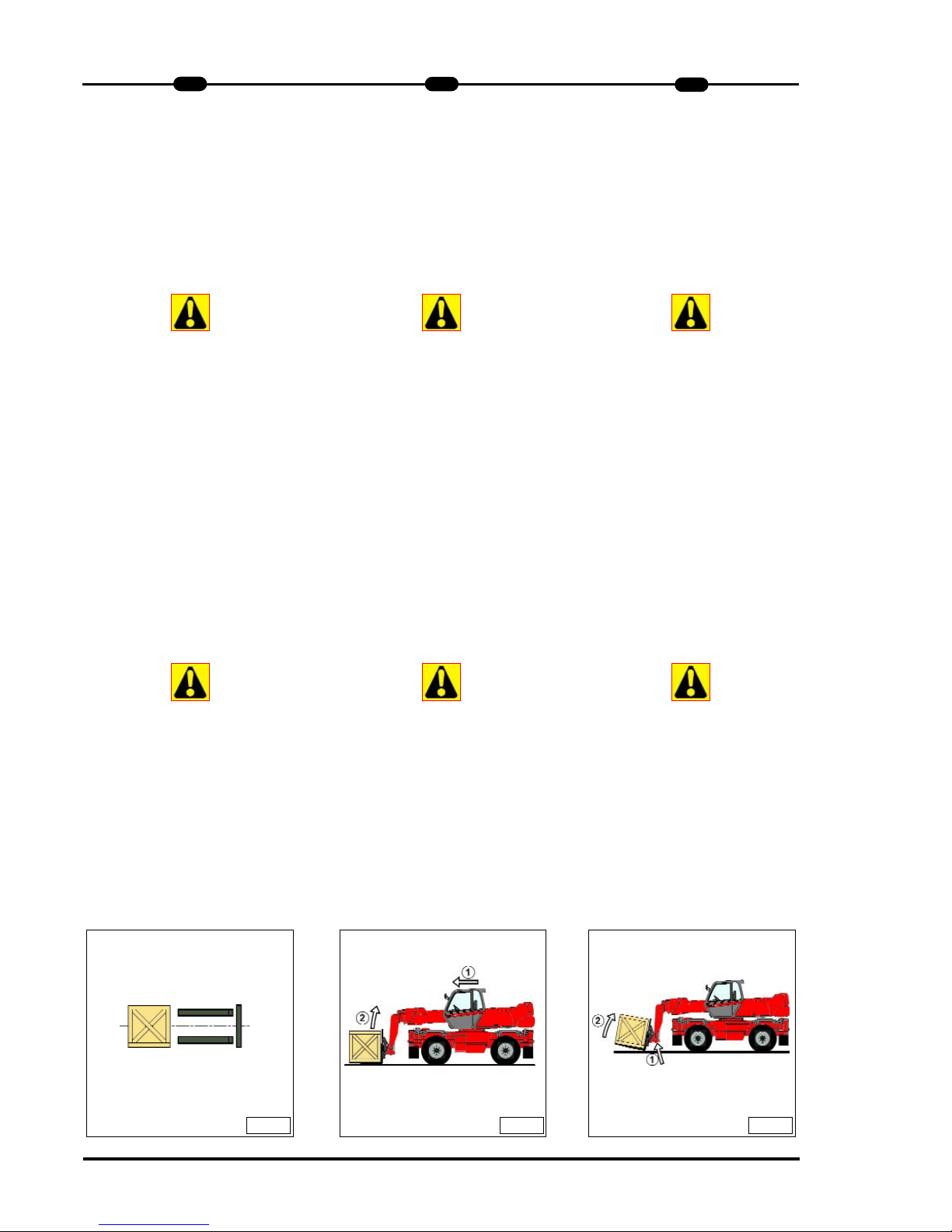
B - Taking up a load on the ground.
- Position the lift truck perpendicular to
the load, with the jib retracted and the
forks in a horizontal position (Fig. C).
- Adjust the fork spread and centering in
connection with the load (Fig. D)
(Optional solutions exist, consult your
dealer).
Beware of the risks of trapping or squa-
shing limbs when manually adjusting
the forks. Always maintain an equal
distance between the forks and the cen-
tre of the carriage in order to keep the
load completely stable.
- Slowly move the life truck forward (1)
and stop with the forks in front of the
load (Fig. E), if necessary, slightly lift
the jib (2) while taking up the load.
- Apply the parking brake and place the
forward/reverse lever in neutral.
- Slightly lift the load (1), tilt the carriage
backwards (2) in the transport position
(Fig. F).
Tilt the carriage sufficiently backwards
to ensure the load’s stability when
braking whilst maintaining the load
balance.
B - Aufnahme einer Last vom Boden.
- Mit dem Teleskoplader die Last bei eingefahrenem Ausleger und waagerechten Gabelzinken rechtwinklig anfahren
(Abb. C).
- Abstand und Zentrierung der
Gabelzinken der Last anpassen (Abb.
D) (Es gibt Sonderausstattungen, fragen Sie Ihren oder Vertragshändler).
Beachten Sie die Gefahr eines
Verklemmens oder Quetschens von
Körpergliedern beim manuellen
Anpassen der Gabelzinken.. Halten Sie
immer gleichen Abstand zwischen den
Gabeln und der Mitte der
Werkzeugaufnahme,, damit die Last
stabil bleibt.
- Mit dem Teleskoplader langsam
vorwärts fahren (1) und die
Gabelzinken vor der Last zum
Anschlag bringen (Abb. E). Falls nötig,
während der Aufnahme der Last den
Teleskop leicht anheben (2).
- Handbremse anziehen und den Hebel
des Fahrtrichtungswahlschalters in
Neutrallstellung bringen.
- Die Last anheben (1), die
Werkzeugaufnahmeenach hinten in
Transportstellung kippen (2) (Abb. F).
Neigen Sie die Last ausreichend weit
nach hinten, um ihre Stabilität sicherzustellen (Gefahr des Abstürzens der Last
beim Bremsen), ohne jedoch deren
Gleichgewicht zu beeinträchtigen.
22
1
MRT 1432 - 1635 M
SS
eries
B - Prelevare un carico dal suolo.
- Avvicinare il carrello elevatore perpendicolarmente al carico, con il braccio
rientrato e le forche orizzontali (Fig. C).
- Regolare lo scarto e il centraggio delle
forche rispetto al carico (Fig. D)
(Esistono soluzioni opzionali ; per maggiori informazioni, rivolgetevi al vostro
agente o concessionario).
Attenzione ai rischi di pizzicamento o di
schiacciamento degli arti durante le
regolazioni manuali delle forche.
Mantenere sempre una distanza uguale
tra le forche e l’asse centrale della tavo-
la per garantire la perfetta stabilità
del carico.
- Far avanzare lentamente il carrello elevatore (1), e portare le forche contro il
carico (Fig. E), se occorre alzare leggermente il braccio (2) durante il prelevamento del carico.
- Azionare il freno di stazionamento e
mettere la leva dell'invertitore di marcia
in folle.
- Sollevare leggermente il carico (1),
inclinare il portaforche (2) indietro in
posizione di trasporto (Fig. F).
Inclinare sufficientemente il carico all’indietro per assicurarne la stabilità (perdi-
ta del carico durante la frenata) facendo
però attenzione a non modificarne l’e-
quilibrio.
IT
EN
DE
D E F
Page 53

C - Taking up a high load on tyres.
Under no circumstances should you
pick up a load if the lift truck is not in a
horizontal position. (See paragraph : G HORIZONTAL POSITION OF THE LIFT
TRUCK in the chapter : LOAD HAND-
LING).
- Ensure that the forks will easily pass
under the load.
- Position the lift truck perpendicular to
the load with the forks in a horizontal
position (Fig. G) manoeuvring gently
and carefully (See paragraph : E VISIBILITY in the chapter : HANDLING
INSTRUCTIONS for visibility of the
road).
Always think about keeping the distance
necessary to fit the forks under the load,
between the pile and the lift truck (Fig.
G) and use the shortest possible
length of jib.
- Stop with the forks in front of the load
(Fig. H). Apply the parking brake and
place the forward/reverse lever in neutral.
- Slightly lift the load (1) and incline the
forks carriage (2) backwards to stabilize the load (Fig. I).
C - Aufnahme einer Last auf
Reifen.
Sie dürfen eine Last auf keinen Fall auf-
nehmen, wenn der Gabelstapler nicht
horizontal steht (Siehe Absatz : G -
HORIZONTALLAGE DES GABELSTA-
PLERS im Kapitel : HANDHABUNG
EINER LAST).
- Überzeugen Sie sich davon,, daß die
Gabelzinken leicht unter der Last hindurch passen.
- Mit dem Teleskoplader die Last mit
waagerechten Gabeln rechtwinklig
anfahren (Abb. G), dabei langsam und
vorsichtig vorgehen (Siehe Absatz : E SICHT im Kapitel : HANDHABUNGSANWEISUNGEN für die Sicht auf die
Fahrbahn)).
Denken Sie immer daran, daß, zum
Einführen der Gabelzinken unter der
Last der notwendigen Abstand zwi-
schen der Last und dem Teleskoplader
einzuhalten (Abb. G) dabei den
Teleskop so kurz wie möglich halten.
- Die Gabelzinken vor der Last zum
Anschlag bringen (Abb. H).
Handbremse anziehen und den Hebel
des Fahrtrichtungswahlschalters in
Neutralstellung bringen.
- Die Last leicht anheben (1) und den
Gabelträger zum Stabilisieren der Last
nach hinten neigen (2) (Abb. I).
C - Prelevare un carico in alto su
pneumatici.
È tassativamente vietato prelevare un
carico se il carrello elevatore non è in
piano (Vedi paragrafo : G -
ORIZZONTALITÀ DEL CARRELLO
ELEVATORE nel capitolo : MOVIMEN-
TAZIONE DI UN CARICO).
- Verificare che le forche passino facilmente sotto il carico.
- Avvicinare il carrello elevatore perpendicolarmente al carico con le forche
orizzontali (Fig. G), manovrando dolcemente e con prudenza (Vedi paragrafo
: E - VISIBILITÀ nel capitolo : ISTRUZIONI PER LA MOVIMENTAZIONE
relativo alla visibilità sul percorso).
Ricordandosi di mantenere sempre la
distanza necessaria per inserire le for-
che sotto il carico, tra la pila e il carrello
elevatore (Fig. G), utilizzando la lun-
ghezza minima possibile del braccio.
- Portare le forche contro il carico (Fig.
H). Tirare il freno di stazionamento e
mettere la leva dell'invertitore di marcia
in folle.
- Sollevare leggermente il carico (1) e
inclinare il portaforche (2) indietro per
stabilizzare il carico (Fig. I).
MRT 1432 - 1635 M
SS
eries
IT
EN
DE
1
23
G H I
Page 54

24
1
MRT 1432 - 1635 M
SS
eries
IT
Tilt the load sufficiently backwards to
ensure its stability (loss of load on
braking) without upsetting the balance of
the load in so doing.
- If possible (Fig. J) lower the load
without shifting the lift truck. Lift the jib
(1) to release the load, retract (2) and
lower the jib (3) to bring the load into
the transport position (Fig. L).
- If this is not possible, back the lift truck
up. (Fig. K) Manoeuvring very gently
and carefully (See paragraph : E - VISIBILITY in the chapter : HANDLING
INSTRUCTIONS for visibility of the
road), back up the lift truck (1) to release the load, retract (2) and lower the jib
(3) to bring the load into the transport
position (Fig. L).
D - Laying a high load on tyres
Under no circumstances should you lay
down a load if the lift truck is not a hori-
zontal position. (See paragraph : G -
HORIZONTAL POSITION OF THE LIFT
TRUCK in the chapter : LOAD HAND-
LING).
Neigen Sie die Last ausreichend weit
nach hinten, um ihre Stabilität sicherzustellen (Gefahr des Abstürzens der Last
beim Bremsen), ohne jedoch deren
Gleichgewicht zu beeinträchtigen.
- Soweit möglich (Abb. J), die Last
absenken, ohne den Teleskopladerr zu
bewegen. Den Teleskop anheben (1),
um die Last frei zu fahren, den
Teleskopr einfahren (2) und den
Teleskop absenken (3), um die Last in
Transportstellung zu bringen (Abb. L).
- Sollte dies nicht möglich sein, mit dem
Teleskoplader zurückfahren (Abb. K).
Durch sehr langsames und vorsichtiges Fahren (Siehe Absatz : E - SICHT
im Kapitel : HANDHABUNGSANWEISUNGEN für die Sicht auf dem
Fahrweg), den Teleskoplader zurücksetzen (1), um die Last frei zu fahren,
den Teleskop einfahren (2) und den
Ausleger absenken (3), um die Last in
Transportstellung zu bringen (Abb. L).
D - Ablegen einer Last auf Reifen.
Sie dürfen auf keinen Fall eine Last
ablegen, wenn der Teleskoplader nicht
horizontal steht (Siehe Absatz : G -
HORIZONTALLAGE DES GABELSTA-
PLERS im Kapitel : HANDHABUNG
EINER LAST).
Inclinare sufficientemente il carico all’indietro per assicurarne la stabilità (perdita del carico durante la frenata) facendo
però attenzione a non modificarne l’e-
quilibrio.
- Se possibile (Fig. J), abbassare il carico senza spostare il carrello elevatore.
Alzare il braccio (1) per allontanare il
carico, far rientrare (2) e abbassare il
braccio (3) per portare il carico in posizione di trasporto (Fig. L).
- Se ciò non fosse possibile, arretrare il
carrello elevatore (Fig. K). Manovrando
molto dolcemente e con estrema prudenza (Vedi paragrafo : E - VISIBILITÀ
nel capitolo : ISTRUZIONI PER LA
MOVIMENTAZIONE relativo alla visibilità sul percorso), arretrare il carrello
elevatore (1) per allontanare il carico,
far rientrare (2) e abbassare il braccio
(3) per portare il carico in posizione di
trasporto (Fig. L).
D - Posare un carico in alto su
pneumatici.
È tassativamente vietato depositare un
carico se il carrello elevatore non è in
piano (Vedi paragrafo : G -
ORIZZONTALITÀ DEL CARRELLO
ELEVATORE, nel capitolo : MOVIMEN-
TAZIONE DI UN CARICO).
EN
DE
J
K
L
Page 55

- Approach the load in the transport
position in front of the pile (Fig. L).
- Lift and extend the jib (1) (2) until the
load is above the pile, if necessary
move the lift truck forward (3) (Fig. M)
manoeuvring very gently and carefully
(See paragraph : E - VISIBILITY in the
chapter : HANDLING INSTRUCTIONS
for visibility of the road). Apply the
parking brake and place the
forward/reverse lever in neutral.
- Place the load in a horizontal position
and lay it down on the pile by lowering
and retracting the jib (1) (2) in order to
position the load correctly (Fig. N).
- Free the forks by alternately retracting
and lifting the jib (3) (Fig. N) or, if possible, by reversing the lift truck (3) (See
paragraph : E - VISIBILITY in the
chapter : HANDLING INSTRUCTIONS
for visibility of the road). Then bring the
jib into the transport position.
E - Taking up a load without pallet
- Tilt the carriage (1) forwards and
extend the jib (2) while simultaneously
crowding the carriage backwards to
slip the forks under the load (Fig. O). If
necessary, wedge the load.
F - Load status indicator.
- Always watch the load status indicator
while handling a load.
- Die Last in Transportposition vor den
Stapel bringen (Abb. L).
- Den Teleskop heben und ausfahren (1)
(2), bis die Last sich über dem Stapel
befindet, falls nötig mit dem
Teleskoplader vorfahren (3) (Abb. M),
dabei sehr langsam und vorsichtig vorgehen (Siehe Absatz : E - SICHT im
Kapitel : HANDHABUNGSANWEISUNGEN für die Sicht auf dem Fahrweg).
Handbremse anziehen und den Hebel
des Fahrtrichtungswahlschalter in
Neutralstellung bringen.
- Die Last in die Waagerechte bringen
und auf den Stapel setzen, dabei durch
Absenken und Einfahren des
Auslegers (1) (2) die Last richtig positionieren (Abb. N).
- Die Gabeln durch abwechselndes
Einfahren und Anheben des Auslegers
(3) (Abb. N) oder, falls möglich, durch
Rückwärtsfahren des Teleskoplader (3)
frei fahren (Siehe Absatz : E - SICHT
im Kapitel : HANDHABUNGSANWEISUNGEN für die Sicht auf dem
Fahrweg). Anschließend den Teleskop
in Transportstellung bringen.
E - Aufnahme einer nicht
palettierten Last.
- Den Gabelträger nach vorn neigen (1)
und den Teleskop ausfahren (2), dabei
den Gabelträger wieder nach hinten
neigen (3) um die Gabeln unter die
Last zu schieben (Abb. O). Falls nötig,
Last verkeilen.
F - Anzeige des Ladezustands.
- Bei der Handhabung immer die
Lastanzeige beobachten.
- Avvicinare il carico in posizione di
trasporto davanti alla pila (Fig. L).
- Alzare e allungare il braccio (1) (2) fino
a quando il carico è al disopra della
pila, se occorre far avanzare il carrello
elevatore (3) (Fig. M) manovrando dolcemente e con prudenza (Vedi paragrafo : E - VISIBILITÀ nel capitolo :
ISTRUZIONI PER LA MOVIMENTAZIONE relativo alla visibilità sul percorso). Azionare il freno di stazionamento
e mettere la leva dell'invertitore di marcia in folle.
- Posizionare il carico orizzontalmente e
posarlo sulla pila, abbassando e rientrando il braccio (1) (2) per posizionare
correttamente il carico (Fig. N).
- Liberare le forche, facendo alternativa-
mente rientrare e alzare il braccio (3)
(Fig. N), o se possibile, facendo indietreggiare il carrello elevatore (3) (Vedi
paragrafo : E - VISIBILITÀ nel
capitolo : ISTRUZIONI PER LA MOVIMENTAZIONE relativo alla visibilità sul
percorso). Quindi portare il braccio in
posizione di trasporto.
E - Prelevare un carico senza pallet
- Inclinare le forche (1) in avanti e allun-
gare il braccio (2) inclinando contemporaneamente le forche (3) indietro per
inserire le forche sotto il carico (Fig.O).
Se necessario zeppare il carico.
F - Dispositivo indicatore di stato di
carico.
- Osservare sempre l'indicatore di stato
di carico durante la movimentazione.
MRT 1432 - 1635 M
SS
eries
IT
EN
DE
1
25
M
N O
Page 56

26
1
MRT 1432 - 1635 M
SS
eries
IT
If the load status indicator alarm is acti-
ved, do not carry out the movements
said to be "WORSENING", which are
the following :
A - Extend the jib.
B - Lower the jib.
- If the load status indicator alarm is
actived, carry out in all security move
ments in the following order (Fig. P) :
1 - Fully retract the jib.
2 - If it’s necessary lift the jib
3 - Lower the jib in order to lay the load.
Lift truck with level corrector
- Correct the slope using the hydraulic
control and check the horizontal position on the level before lifting the
boom(See chapter : INSTRUMENTS
AND CONTROLS in paragraph : 2 -
DESCRIPTION).
Apart from the transverse slope of the
ground, several parameters can upset
the horizontal position of the lift truck.
• The tyre pressures.
• The stability of the ground.
• The balance of the load.
• Strong wind or stormy conditions.
Before any handling work, check the
points above and ensure that the lift
truck is completely horizontal.
(See bubble level)
Sollte die Lastanzeige einen Alarm
anzeigen, dürfen auf keinen Fall soge-
nannte "ERSCHWERENDE"
Bewegungen ausgeführt werden,
und zwar :
A - Ausfahren des Auslegers.
B - Absenken des Auslegers.
- In diesem Fall dürfen nur positive
Bewegungen ausgeführt
werden.Bewegungen in folgender
Reihenfolge ausführen (Abb. P) :
1 - Teleskop völlig einfahren.
2 - Teleskop absenken und die Last
3 - Ausleger absenken und die Last
ablegen.
Gabelstapler mit neigungsausgleich.
- Die Neigung durch Betätigen der
hydraulischen Steuerung korrigieren
und die Horizontallage auf dem Pegel
prüfen (Siehe Kapitel : STEUER- UND
BEDIENUNGSINSTRUMENTE,
Abschnitt : 2 - BESCHREIBUNG).
Mit Ausnahme des transversalen
Geländegefälles, können mehrere
Parameter die Horizontallage des
Gabelstaplers beeinträchtigen.
• Der Druckzustand der Bereifung.
• Die Stabilität des Bodens.
• Das Gleichgewicht der Last.
• Starker Wind oder Sturm.
Vor den Einsatz des Teleskoplader sind
die oben genannten Punkte zu prüfen.
Sicherstellen, dass der Gabelstapler
perfekt horizontal steht.
Quando l'indicatore di stato di carico è
in allarme, non bisogna in alcun caso:
A - Far uscire il braccio.
B - Abbassare il braccio.
- Se l'indicatore di stato di carico è in
allarme, effettuare i movimenti sgravanti, nel seguente ordine (Fig. P) :
1 - Rientrare il braccio al massimo.
2 -Se necesario alzare il braccio
3 - Abbassare il braccio in modo da
posare il carico.
Carrello elevatore con correttore d’inclinazione.
- Correggere l’inclinazione, agendo sul
comando idraulico e verificare l’orizzontalità sulla livella prima di sollevar il
bracio(Vedi capitolo : STRUMENTI DI
CONTROLLO E DI COMANDO, nella
parte : 2 - DESCRIZIONE).
Oltre alla pendenza trasversale del terreno, altri parametri possono incidere
sull’orizzontalità del carrello elevatore.
• Lo stato e la pressione dei pneumatici.
• La stabilità del terreno.
• L’equilibrio del carico.
• Il vento forte o la tempesta.
Prima di ogni movimentazione, controllare le condizioni sopraelencate e verificare che il carrello elevatore sia perfet-
tamente orizzontale.
(Controllare sulla livella a bolla)
EN
DE
P
Page 57

MRT 1432 - 1635 M
SS
eries
IT
EN
DE
1
27
MAINTENANCE INSTRUCTIONS OF
THE LIFT TRUCK
Maintenance instructions.
A - General.
- Read the operator's manual carefully
and ensure you understand it.
- Stop the I.C. engine, when an
intervention is necessary.
- Wear clothes suitable for the maintenance of the lift truck, avoid wearing
jewellery and loose clothes. Tie and
protect your hair, if necessary.
- Ensure the area is sufficiently ventilated before starting the lift truck.
Make sure that the disposal of process
materials and of spare parts is
carried out in total safety
and in a ecological way.
- Carry out all repairs immediately, even
if the repairs concerned are minor.
- Repair all leaks immediately, even if
the leak concerned is minor.
- Do not attempt to loosen unions, hoses
or any hydraulic component with the
circuit under pressure.
The handling and removal of the balan-
cing valves or safety valves which may
be fitted to the cylinders of your lift truck
can be dangerous. A balancing valve
must only be removed when the cylin-
der concerned is at rest and the hydrau-
lic circuit is depressurised.
This operation can only be carried
out by authorised staff.
WARTUNGSANWEISUNGEN DES
TELESKOPLADER
Wartungsanweisungen.
A - Allgemeines.
- Die Bedienungsanleitung sorgfältig
lesen und sicherstellen, daß die Inhalte
und Vorgehensweisen verstanden wurden. .
- Vor jedem Eingriff an dem
Teleskoplader den Motor abstellen.
- Für die Wartung des Teleskoplader
geeignete Kleidung tragen, Schmuck
und weite Kleidung vermeiden.
Gegebenenfalls Haare hochbinden und
schützen.
- Vor dem Starten des Teleskopladers für
ausreichende Belüftung sorgen.
Darauf achten, daß die Entsorgung der
Verbrauchsstoffe und der Altteile sicher
und umweltfreundlich erfolgt.
- Notwendige Reparaturen, selbst kleine,
sofort durchführen.
- Jede Leckage, selbst kleinere, sofort
reparieren.
- Versuchen Sie niemals, Hydraulische
Verbindungen,Schläuche,oder
Hydraulikkomponenten die unter Druck
stejhen zu öffnen.
Jede Einstellungsänderung oder der
Ausbau der Ausgleichventile oder der
Sicherheitventile, mit denen die Zylinder
des Teleskoplader ausgestattet sein
können, kann sich als gefährlich
erweisen. Ein Ausgleichventil darf nur
ausgebaut werden, wenn der
entsprechende Zylinder in Ruhestellung
und der Hydraulikkreis drucklos ist.
Dieser Eingriff darf nur von
authorisiertem Personal durch-
geführt
werden.
ISTRUZIONI DI MANUTENZIONE DEL
CARRELLO ELEVATORE
Istruzioni per la manutenzione.
A - Istruzioni generali.
- Leggere con attenzione e comprendere il manuale d'istruzioni.
- Spegnere il motore termico prima di
ogni intervento sul carrello elevatore.
- Indossare abbigliamento adeguato alle
operazioni di manutenzione del carrello
elevatore, evitando i gioielli e gli indumenti troppo larghi. Se occorre, legare
e proteggere i capelli.
- Assicurarsi che il locale sia
sufficientemente ventilato prima di
mettere in moto il carrello elevatore.
Porre particolare attenzione allo smalti-
mento dei materiali di consumo e dei
pezzi usati, verificando che venga effet-
tuato nella massima sicurezza
e in modo ecologico.
- Effettuare le riparazioni necessarie,
anche le minori, immediatamente.
- Riparare ogni perdita, anche minima,
immediatamente.
- Non cercare di allentare i raccordi, i
flessibili o un componente idraulico,
con il circuito in pressione.
La modifica della regolazione e lo
smontaggio delle valvole di equilibratura
che o delle valvole di sicurezza che, a
volte, equipaggiano i martinetti del car-
rello elevatore, possono rivelarsi perico-
losi. Una valvola di equilibratura può
essere smontata solo con il martinetto
interessato a riposo e con il circuito
idraulico senzapressione.
Tale operazione può essere effettua-
ta solo da personale autorizzato.
Page 58

28
1
MRT 1432 - 1635 M
SS
eries
IT
- Do not smoke or approach the lift truck
with a flame, when the fuel tank is
open or is being filled.
- Take care not to burn yourself
(Exhaust, radiator, I.C. engine, etc.).
- Disconnect the negative cable terminal
(-) from the top of the battery before
working on the electrical circuit or on
the lift truck (e.g. : Welding).
- Do not drop metallic items on the battery.
- When carrying out electric welding
work on the lift truck, connect the
negative cable from the equipment
directly to the part being welded, so as
to avoid high tension current passing
through the alternator.
B - Maintenance.
- The maintenance and the keeping in
compliance of the lift truck are compulsory.
- Carry out daily maintenance (See
chapter : A - DAILY OR EVERY 10
HOURS SERVICE in paragraph : 3 MAINTENANCE).
- Do not run the I.C. engine without air
filter, or with oil, water or fuel leaks.
Wait for the I. C engine to cool before
removing the radiator cap.
- Change the filter cartridges (See servicing schedules in chapter : FILTERS CARTRIDGES AND BELTS in
paragraph : 3 - MAINTENANCE).
C - Levels.
- Use the recommended lubricants
(Never use contaminated lubricants).
- Do not fill the fuel tank when the I.C.
engine is running.
- Only fill up the fuel tank in areas
specified for this purpose.
- Nicht rauchen oder sich mit einer offenen Flamme dem Teleskoplader
nähern, wenn dessen Kraftstofftank
offen ist oder gefüllt wird.
- Vorsicht, Verbrennungsgefahr (Auspuff,
Kühler, Verbrennungsmotor, usw.).
- Vor Arbeiten am Stromkreis oder am
Teleskoplader(Z. B. Schweißen) die
Minusklemme (-) der Batterie abklemmen.
- Keine Metallteile auf die Batterie legen.
- Zur Durchführung von
Elektroschweißarbeiten am
Teleskoplader, die Minusklemme des
Schweißgerätes direkt an das zu
schweißende Teil legen, damit der
Strom nicht durch die Lichtmaschine
fließt.
B - Instandhaltung.
- Der Teleskoplader muß zwangsläufig
instand und in konformem Zustand
gehalten werden.
- Tägliche Instandhaltung durchführen
(Siehe Kapitel : A - TÄGLICH ODER
ALLE 10 BETRIEBSSTUNDEN,
Abschnitt : 3 - WARTUNG).
- Den Verbrennungsmotor nicht ohne
Luftfilter oder mit Öl-, Wasser- oder
Kraftstoffleckagen in Betrieb nehmen.
Vor dem Entfernen des
Kühlerverschlusses sicherstellen, daß
der Motor abgekühlt ist.
VERBRENNUNGSGEFAHR
- Filterpatronen auswechseln (Siehe
Austauschhäufigkeit im Kapitel : FILTERELEMENTE UND KEILRIEMEN,
Abschnitt : 3 - WARTUNG).
C - Flüssigkeitsstand.
- Nur empfohlenen Schmiermittel einset-
zen (Auf keinen Fall gebrauchte
Schmiermittel verwenden).
- Den Kraftstofftank nicht bei laufendem
Motor befüllen.
- Den Teleskoplader nur an den dafür
vorgesehenen Stellen auftanken.
- Non fumare o avvicinarsi al carrello
elevatore con fiamme libere quando il
serbatoio del combustibile è aperto o
in fase di riempimento.
- Attenzione ai rischi di ustioni
(Scappamento, radiatore, motore
termico, ecc.).
- Scollegare il capocorda negativo (-)
dalla batteria prima di lavorare sull'impianto elettrico o sul carrello elevatore
(Es. : Saldatura).
- Non posare pezzi metallici sulla
batteria.
- Per effettuare una saldatura elettrica
sul carrello elevatore, porre la pinza
del cavo negativo della saldatrice direttamente sul pezzo da saldare, onde
evitare che la corrente molto forte
attraversi l'alternatore.
B - Manutenzione.
- La manutenzione e il mantenimento
dello stato di conformità del carrello
elevatore sono obbligatori.
- Effettuare la manutenzione giornaliera
(Vedi capitolo : A - OGNI GIORNO O
OGNI 10 ORE DI FUNZIONAMENTO
nella parte : 3 - MANUTENZIONE).
- Non far funzionare il motore termico
senza il filtro dell'aria o con perdite
d'olio, d'acqua o di combustibile.
Aspettare il raffreddamento del
motore termico prima di rimuovere
il tappo del radiatore.
- Sostituire le cartucce dei filtri (Vedi
periodicità di sostituzione nel capitolo
ELEMENTI FILTRANTI E CINGHIE
nella parte : 3 - MANUTENZIONE).
C - Livelli.
- Utilizzare i lubrificanti raccomandati
(Non utilizzare mai lubrificanti usati).
- Non riempire il serbatoio del
combustibile quando il motore termico
è in funzione.
- Effettuare il pieno di combustibile solo
negli appositi spazi previsti a tale
scopo.
EN
DE
Page 59

MRT 1432 - 1635 M
SS
eries
IT
EN
DE
1
29
D - Washing.
- Clean the lift truck or at least the area
concerned before any intervention.
- Remember to close the door and the
rear
window of the cab.
- During washing, avoid the articulations
and electrical components and
connections.
If necessary, protect against penetration
of water, steam or cleaning agents,
components susceptible of being dama-
ged, particularly electrical components
and connections and the injection
pump.
- Clean the lift truck of any fuel, oil or
grease trace.
For any intervention other than
regular maintenance, consult your
dealer.
D - Reinigen.
- Den Teleskoplader oder zumindest den
betroffenen Bereich vor jedem Eingriff
reinigen.
- Denken Sie daran, die Tür und das
hintere Fenster des Führerstands zu
schließen.
-, Gelenke und elektrische
Komponenten und Anschlüsse
vor dem Reinigen abdecken..
Falls nötig Komponenten, die beschä-
digt werden könnten, insbesondere
elektrische Komponenten und
Anschlüsse und die Einspritzpumpe, vor
dem Eindringen von Wasser, Dampf
oder Reinigungsmitteln schützen.
- Jede Spur von Kraftstoff, Öl oder Fett
vom Gabelstapler entfernen.
Für jeden anderen Eingriff als die
normale Instandhaltung fragen Sie
Ihren Vertreter oder
Vertragshändler.
D - Lavaggio.
- Pulire il carrello elevatore, o al meno la
parte interessata, prima di ogni
intervento.
- Non dimenticare di chiudere la porta e
il lunotto posteriore della cabina.
- Durante il lavaggio, evitare di bagnare
le articolazioni, i componenti e
collegamenti elettrici.
Se necessario proteggere dall'acqua,
dal vapore o dai prodotti detergenti, i
componenti che rischiano di venire dan-
neggiati, in particolare i componenti e i
collegamenti elettrici e la pompa
d'iniezione.
- Pulire il carrello elevatore da ogni traccia di combustibile, d'olio o di grasso.
Per ogni intervento che non rientri
nella manutenzione ordinaria, rivolgetevi al vostro agente o concessionario.
Page 60

BEFORE STARTING UP A NEW LIFT
TRUCK
Introduction.
- Our lift trucks have been designed for
easy handling by the operator and
maximum ease of maintenance for the
mechanic.
- However, before commencing to operate the lift truck, the user should carefully read and understand the various
chapters of this manual which has
been provided to solve driving and
maintenance problems. By following
these instructions the user will be able
to take full advantage of the versatility
of this lift truck.
- The operator must familiarize himself
with the positions and functions of all
the controls and instruments before
operating the lift truck.
Do not attempt to start a new lift truck
before the following checks have been
carried out :
Lubrication.
- Check that all the correct grades of oils
and greases that are required are available ; see chapter : SERVICING
SCHEDULE in paragraph : 3 - MAINTENANCE and top up if necessary.
For operation under average climatic
conditions, i.e. : between -15 °C and
+ 35 °C, correct levels of lubricants in all
the circuits are checked in production.
For operation under more severe clima-
tic conditions, before starting up, it is
necessary to drain all the circuits, then
ensure correct levels of lubricants using
lubricants properly suited to the relevant
ambient temperatures. It is the same for
the cooling liquid (Contact your dealer
for information, if necessary).
Dry air filter.
- Ensure that the air filter is undamaged
and not blocked.
- Tighten the fastening devices if
necessary.
Never run the I.C. engine with the air fil-
ter removed or damaged.
Cooling circuit
- Always check the cooling liquid level
before starting up the lift truck.
30
1
MRT 1432 - 1635 M
SS
eries
VOR DER INBETRIEBNAHME EINES
NEUEN TELESKOPLADER
Einleitung.
- Unsere Teleskoplader wurden dahingehend entwickelt, dem Fahrer eine
einfache Bedienung und eine so einfach wie möglich gestaltete Wartung zu
bieten.
- Vor der ersten Inbetriebnahme des
Teleskoplader muß der Benutzer jedoch die verschiedenen Kapitel dieser
Bedienungsanleitung sorgfältig lesen
und sicherstellen, daß diedort beschriebenen Inhalte und Vorgehensweisen
verstanden wurden. Die bedienungsanleitung beinhaltet alle Informationen
eventueller Fahr- und
Wartungsprobleme . Wenn diese
Anweisungen befolgt wird, kann der
Benutzer die Kapazitäten des
Teleskoplader voll ausnutzen.
- Der Benutzer muß sich vor dem
Einsatz des Teleskoplader mit der
Lage und der Funktion der verschiedenen Steuer- und
Bedieninstrumente vertraut machen.
Vor dem Starten Ihres neuen
Teleskoplader sollten folgende Punkte
überprüft werden:
Schmierung.
- Die verschiedenen Schmierpunkte und
Flüssigkeitsstände überprüfen, siehe
Kapitel : WARTUNGSINTERVALLE,
Abschnitt : 3 - WARTUNG, und gegebenenfalls vervollständigen.
Die Schmiermittel werden im Werk für
durchschnittliche Klimabedingungen ein-
gefüllt, d. h. -15°C bis + 35°C. Für härte-
re Einsätze muß der Teleskoplader vor
der Inbetriebnahme entleert und mit für
die Umgebungstemperaturen geeigneten Schmiermitteln gefüllt werden. Dies
gilt auch für das Kühlmittel (Erkundigen
Sie sich gegebenenfalls bei Ihrem oder
Vertragshändler).
Luftfilter.
- Überzeugen Sie sich davon, daß sich
der Luftfilter in einem gutem, sauberen
und einwandfreiem Zustand befindet.
Niemals den Teleskoplader ohne Luftfilter
oder mit einem beschädigten Luftfilter
einsetzen.
Kühlkreislauf
- Den Teleskoplader nie in Betrieb
nehmen, wenn man nicht vorher den
Stand der Kühlflüssigkeit geprüft hat.
PRIMA DI AVVIARE UN CARRELLO
NUOVO
Introduzione.
- I nostri carrelli elevatori sono stati progettati per offrire al conduttore la massima semplicità di manovra e una
grande facilità di manutenzione.
- Tuttavia, prima del primo avviamento
del carrello elevatore, l'utilizzatore
dovrà leggere con attenzione e comprendere il presente manuale, redatto
per rispondere a tutti i problemi di
guida e di manutenzione. Seguendo le
istruzioni, l'utilizzatore sarà in grado di
sfruttare al meglio le prestazioni offerte
dal carrello elevatore.
- L'utilizzatore dovrà, prima di utilizzare il
carrello elevatore, conoscere le funzioni e posizioni dei diversi strumenti di
controllo e di comando.
Non avviare mai un nuovo carrello ele-
vatore, prima di aver effettuato i
seguenti controlli :
Ingrassaggio.
- Controllare i vari punti d'ingrassaggio e
i vari livelli, vedi capitolo :
PERIODICITÀ DELLA MANUTENZIONE nella parte : 3 - MANUTENZIONE
e procedere alle eventuali aggiunte.
Il pieno di lubrificanti è già stato effettua-
to in fabbrica, utilizzando lubrificanti per
condizioni climatiche d'uso medie, ossia
da -15°C a + 35°C. Per un utilizzo in
condizioni estreme occorre, prima del-
l'avviamento, svuotare e rifare i pieni,
utilizzando i lubrificanti adatti a tali temperature. Lo stesso vale per il liquido di
raffreddamento (Per maggiori informa-
zioni, rivolgetevi al vostro agente o con-
cessionario).
Filtro a secco dell'aria.
- Accertarsi che il filtro dell'aria sia in
buono stato e non sia intasato.
- Stringere i bloccaggi se occorre.
Non utilizzare mai il carrello elevatore
senza il filtro dell'aria o con un filtro del-
l'aria danneggiato.
Circuito di raffreddamento.
- Non mettere mai in moto il carrello
elevatore senza avere preventivamente
controllato il livello del liquido di
raffreddamento.
IT
EN
DE
Page 61

MRT 1432 - 1635 M
SS
eries
IT
EN
DE
1
31
Braking system.
- Check by a visual examination that
there are no leaks or oil oozing in the
hoses, connections and unions. If
necessary, tighten or repair the defective connections.
- Also check the oil level in the tank.
Tyres.
- Make sure that the wheel nuts are
correctly tightened (See chapter : A DAILY OR EVERY 10 HOURS SERVICE in paragraph : 3 - MAINTENANCE) and that the tyre pressures are
correct (See chapter : CHARACTERISTICS in paragraph : 2 - DESCRIPTION).
Fuel system.
- Check that all fuel lines are secured.
- If necessary drain the fuel filter and
bleed the fuel system of air.
Electrical circuit.
- Check the level and the density of the
electrolyte in the battery (See chapter :
B
- EVERY 50 HOURS SERVICE in
paragraph : 3 - MAINTENANCE).
- Check the components of the electrical
system, the connections and fastening
devices.
If necessary, consult your dealer.
Bremskreis.
- Überzeugen Sie sich durch eine
Sichtkontrolle von de Dichtheit des
Bremssystems
- Ebenfalls den Ölstand im Tank überprüfen.
Reifen.
- Überprüfen Sie die Radmuttern auf
festen Sitz.
(Siehe Kapitel : A - TÄGLICH ODER
ALLE 10 BETRIEBSSTUNDEN,
Abschnitt : 3 - WARTUNG).
Reifendruck prüfen (Siehe Kapitel :
TECHNISCHE DATEN, Abschnitt : 2 -
BESCHREIBUNG).
Kraftstoffsystem.
- Überprüfen Sie das Kraftstoffsystem
auf Dichtheit.
- Gegebenenfalls den Kraftstoffilter
entleeren und das Kraftstoffsystem
entlüften.
Elektrik.
- Stand und Dichte des Elektrolyts in der
Batterie überprüfen (Siehe Kapitel : B ALLE 50 BETRIEBSSTUNDEN,
Abschnitt : 3 - WARTUNG).
- Die verschiedenen Elemente der
Elektrik sowie deren Anschlüsse und
Befestigung überprüfen.
Im Zweifelsfall fragen Sie Ihren
oder Vertragshändler.
Circuito dei freni.
- Verificare che non ci siano perdite o
trasudazioni d'olio sui collegamenti,
flessibili, tubi e raccordi. Se occorre,
ristringere o controllare i collegamenti
difettosi.
- Controllare anche il livello dell'olio nel
serbatoio.
Pneumatici.
- Accertarsi che i bulloni di fissaggio
delle ruote siano stretti a fondo (Vedi
capitolo : A - OGNI GIORNO O OGNI
10 ORE DI FUNZIONAMENTO nella
parte : 3 - MANUTENZIONE) e controllare la pressione dei pneumatici (Vedi
capitolo : CARATTERISTICHE nella
parte : 2 - DESCRIZIONE).
Circuito di alimentazione del
combustibile.
- Verificare la corretta tenuta delle
tubazioni.
- Se necessario, svuotare il filtro del
combustibile e il sistema di
alimentazione.
Impianto elettrico.
- Verificare il livello e la densità
dell'elettrolito nella batteria (Vedi
capitolo : B - OGNI 50 ORE DI
FUNZIONAMENTO nella parte : 3 MANUTENZIONE).
- Controllare i vari componenti
dell'impianto elettrico, i loro
collegamenti e contatti.
In caso di necessità, rivolgetevi al
vostro agente o concessionario.
Page 62

32
1
MRT 1432 - 1635 M
SS
eries
IT
EN
DE
WARNING
USE OF THE SLEWING DEVICE
MRT 1432 - 1635 lift truck is equipped
with a hydraulic slewing device able to
turn through 360° or 400°.
During the slewing action, the automatic
rear axle locking device activates after
more than a 15° turn in order to ensure
greater stability and carrying capacity.
The driver must, however, take the
utmost care and strictly comply with the
following instructions when using this
device:
- Check that the slewing lock pin is not
engaged (see points 3311 and 1133 of the
“INSTRUMENTS AND CONTROLS”
chapter).
- Comply with the curves on the load
chart diagrams
- Check that the hoods and lower part of
the door are closed.
- When the turret slews, check that it
cannot hit against obstructions in the
near vicinity.
- Never drive for long distances with or
without a load, unless the turret has
been aligned.
Road travel :
The hydraulic slewing mechanism must
be locked during road travel. The truck
is equipped with a locking device.
Consult points 1133 and 3311 of the
“INSTRUMENTS AND CONTROLS”
chapter when engaging this device.
USE OF THE OUTRIGGERS
Lift truck MRT 1432 - 1635 has 4 outrig gers with independent control able to
achieve a polygon base of 4 meter of
lenght and 3.8 of widht thus stabilizing
the truck during the work phases.
WARNING
BENUTZUNG DER ROTATIONSVORRICHTUNG
Der Teleskoplader MRT 1432 - 1635 ist mit
einer hydraulischen Rotationsvorrichtung
von durchgehend 360° / 400°.
Um dem Teleskoplader eine bessere
Standsicherheit und eine höhere
Tragefähigkeit zu verleihen, tritt bei der
Rotation nach 15° Verdrehung eine
automatische Vorrichtung in Funktion,
die die Hinterachse blockiert. Trotz dieser automatischen Sicherung muß der
Bediener bei Verwendung der
Rotationsvorrichtung die folgenden
Vorsichtsmaßnahmen beachten:
- sicherstellen, daß der
Rotationsperrzapfen nicht eingerastet ist
(vgl. Punkte "3311" und "1133" des Kapitels
“KONTROLL- UND BEDIENUNGSVORRICHTUNGEN”).
- Die Daten beachten, die in den
Lastdiagrammen stehen.
- Sicherstellen, daß die Hauben und die
untere Kabinentür geschlossen sind.
- Während der Rotation sicherstellen,
daß der Drehturm nicht gegen
Hindernisse in unmittelbarer Nähe stößt.
-Keine langen Fahrbewegungen ausführen, weder mit noch ohne Last, wenn
der Drehturm nicht auf die
Fahrzeugachse ausgerichtet ist.
Strassenverkehr:
Während der Teilnahme am
Straßenverkehr muß die hydraulische
Rotationsvorrichtung verriegelt sein. Der
Teleskoplader ist mit einer
Sperrvorrichtung versehen.
Die Einschaltung dieser Vorrichtung ist
in den Punkten "1133"und "3311" des
Kapitels “KONTROLL- UND BEDIENUNGSVORRICHTUNGEN” beschrieben.
BESTIMMUNGEN FÜR DIE BENUTZUNG
DER STÜTZFÜSSE
Der Teleskoplader MRT 1432 - 1635 ist
mit 4 einzeln zu bet tigenden
Scherenst tzen versehen, die eine
Standfl che von 4 Meter Seitenl nge
und 3,8 Meterbreite verleihen und die
Maschine dadurch standfest und sicher
machen.
AVVERTENZE GENERALI
UTILIZZO DEL DISPOSITIVO DI ROTAZIONE
Il carrello MRT 1432 - 1635 è dotato del
dispositivo di rotazione idraulica a 360°
o 400°.
Durante la rotazione per garantire
migliore stabilità e portata al carrello,
dopo aver superato i 15° di rotazione
entra in funzione il dispositivo automatico di blocco dell' assale posteriore;
nonostante tutto l'operatore per l' utilizzo
di questo dispositivo dovrà fare attenzione e seguire le seguenti raccomandazioni:
- Verificare che il perno di blocco rotazione non sia inserito (vedere punti 3311 e
113
3 del capitolo "STRUMENTI DI CON-
TROLLO E DI COMANDO")
- Attenersi ai dati indicati sui diagrammi
di carico.
- Verificare che i cofani e la portiera inferiore siano chiusi.
- Verificare durante la rotazione che la
torretta non urti ostacoli nelle immediate
vicinanze.
- Non eseguire lunghi spostamenti con e
senza carico se la torretta non è allineata.
Circolazione stradale
Per la circolazione su strada la rotazione
idraulica deve essere bloccata , il carrello è provvisto di un dispositivo di bloccaggio.
Per l' inserimento del dispositivo vedere
punti 1133, e 3311 del capitolo "STRUMEN-
TI DI CONTROLLO E DI COMANDO".
UTILIZZO DEGLI STABILIZZATORI
Il carrello MRT 1432 - 1635 è dotato di 4
stabilizzatori con comando indipendente,
permettono un poligono di appoggio di 4
metri di lunghezza e 3,8 metri di
larghezza dando così alla macchina
stabilità e sicurezza sul lavoro.
Page 63

MRT 1432 - 1635 M
SS
eries
IT
EN
DE
1
33
Per attivare il diagramma portate su
stabilizzatori é necessario che il carrello
appoggi su tutti e 4 gli stabilizzatori.
Verificare lo stato del terreno di lavoro
degli stabilizzatori.
Eseguire operazioni di livellamento del
carrello (con gli stabilizzatori) prima di
sollevare il braccio facendo riferimento
all'apposita livella a bolla sul cruscotto
onde evitare effetti di instabilità dinamica.
Se ci si accorge che la macchina non é
a livello abbassare il braccio e ripetere
l'operazione di messa a livello.
Prima di stabilizzare la macchina con-
trollare che i piedi stabilizzatori
siano nella
posizione cantiere.(FIG.2)
Der
Teleskoplader muß gemäß der
Typengenehmigung nur dann arbeiten,
wenn alle vier Stützen ganz
ausgefahren sind.
- Der arbeite Boden der Stützfüssen
prüfen
- Den Teleskoplader zuerst (mit den
Stützen) nivellieren, bevor der Ausleger
hochgefahren wird. Zum Nivellieren
verwendet man die Wasserwaage auf
dem Armaturenbrett, um Auswirkungen
der dynamischen Standunsicherheit zu
vermeiden.
Wenn man bemerkt, daß die Maschine
nicht eben steht, den Ausleger senken
und die Maschine erneut nivellieren.
Vor deM Ausrichten der maschine, prü-
fen DASS die stützfüsse auf
BAUSTELLENSTELLUNG
AUSgeRICHTet sind.(ABB.2)
To activate the capacity diagram on
outriggers it's necessary that the truck is
on all the 4 outriggers.
- Check the state of the working ground
of the outriggers.
Level the load (with the outriggers)
before lifting the boom. Refer to the
bubble level on the control panel in
order to prevent dynamic instability
effects.
If the truck is not level, lower the arm
are repeat the levelling operation.
Before stabilizing the truck make sure
that the outriggers feet are in a working
position. (FIG.2)
Posizione stradale
Road Position
Strassenstellung
Posizione cantiere
Working position
Baustellenstellung
1
2
3,8 mt
4 mt
3,8 mt
4 mt
Page 64

Page 65

Page 66

Page 67

2
2
--D
D
E
E
S
S
C
C
R
RII
Z
ZII
O
O
N
N
E
E
D
D
E
E
S
S
C
C
R
RII
P
P
T
TII
O
O
N
N
S
S
C
C
H
HII
L
L
D
D
E
E
R
R
U
U
N
N
G
G
Page 68

Page 69

MRT 1432 - 1635 M
SS
eries
IT
EN
DE
2
1
SPECIFICATION
Engine
Type . . . . . . . . . . . . . . .Perkins
Number of cylinders . . .4
Strokes . . . . . . . . . . . . .4
Injection system . . . . . .Direct
Firing order . . . . . . . . .1.3.4.2.
Displacement . . . . . . . .4400 cm
3
Bore . . . . . . . . . . . . . . .105 mm
Stroke . . . . . . . . . . . . . .127 mm
Compression ratio . . . .17.5:1
Nominal rate . . . . . . . .2200 rpm
Idle rate . . . . . . . . . . . .800 rpm
Maximum idle rate . . . .2400 rpm
ISO/TR 14396
rating . . . . . . . . . . . . . .101 CV-74.5 KW
. . . . . . . . . . . . . . . . . . .a 2200 rpm
Maximum torque . . . . .412 Nm a
1400 rpm
Cooling system
Type . . . . . . . . . . . . . . .Water cooled
Blower
fan speed . . . . . . . . . . .2300 rpm
Number of blades . . . .7
Diameter . . . . . . . . . . .550 mm
Thermostat
Opening start . . . . . . . .75°C / 85°C
Complete opening . . . .92°C / 98°C
Electrical circuit
Ground . . . . . . . . . . . . .Negative
Battery . . . . . . . . . . . . .12 V - 120 Ah
Voltage regulator . . . . .Built into
the alternator
Starting . . . . . . . . . . . . .12 V
Transmission unit
Type . . . . . . . . . . . . . . .RexRoth hydro
static, variable
displacement
pump and motor
Gearshift . . . . . . . . . . .Mechanical with
hydraulic control
N° of forward gears . . .2
N° of reverse gears . .2
Reverser . . . . . . . . . . .Electromagnetic
CARATTERISTICHE
Motore
Tipo . . . . . . . . . . . . . . .Perkins
Numero cilindri . . . . . . .4
Numero tempi . . . . . . .4
Sistema d'iniezione . . .Diretta
Ordine d'accensione . .1.3.4.2.
Cilindrata . . . . . . . . . . .4400 cm
3
Alesaggio . . . . . . . . . . .105 mm
Corsa . . . . . . . . . . . . . .127 mm
Rapporto volumetrico .17.5:1
Regime nominale . . . . .2200 min
-1
Regime al minimo . . . .800 min
-1
Regime max a vuoto . .2400 min-1
Potenza
ISO/TR 14396 . . . . . . .101 CV-74.5 KW
. . . . . . . . . . . . . . . . . . .a 2200 min
-1
Coppia massima . . . . .412 Nm a
1400 min
-1
Circuito di raffreddamento
Tipo . . . . . . . . . . . . . . .Ad acqua
Velocità ventilatore
soffiante . . . . . . . . . . . .2300 min
-1
Numero delle pale 7
Diametro . . . . . . . . . . .550 mm
Termostato
Inizio d'apertura . . . . . .75°C / 85°C
Apertura completa . . . .92°C / 98°C
Impianto elettrico
Massa . . . . . . . . . . . . .Negativa
Batteria . . . . . . . . . . . .12 V - 120 Ah
Regolatore tensione . .Incorporato
nell'alternatore
Avviamento . . . . . . . . .12 V
Trasmissione
Tipo . . . . . . . . . . . . . . .Idrostatica
. . . . . . . . . . . . . . . . . . .RexRoth, pompa
e motore a
cilindrata
variabile
Cambio . . . . . . . . . . . .Meccanico a
comando idraulico
N° marce avanti . . . . . .2
N° marce indietro . . . . .2
Inversore di marcia . . .Elettromagnetico
TECHNISCHE DATEN
Motor
Motortyp . . . . . . . . . . . .Perkins
Zylinderzahl . . . . . . . . .4
Takte . . . . . . . . . . . . . .4
Einspritzsystem . . . . . .Direkt
Zündfolge . . . . . . . . . .1.3.4.2.
Ventilspiel (kalt)
Hubraum . . . . . . . . . . .4400 cm
3
Bohrung . . . . . . . . . . . .105 mm
Hub . . . . . . . . . . . . . . .127 mm
Verdichtungsverhältnis .17.5:1
Nenndrehzahl . . . . . . .2200 U/min
Leerlaufdrehzahl . . . . .800 U/min
Obere Leerlaufdrehzahl2400 U/min
Leistung
ISO/TR 14396 . . . . . . .101 CV-74.5 KW
. . . . . . . . . . . . . . . . . . .a 2200 U/min
Max. Drehmoment . . . .412 Nm bei
1400 U/min
Kühlsystem
Typ . . . . . . . . . . . . . . . .Wasserkreiskauf
Geschwindigkeit
Sauglüfter . . . . . . . . . .2300 rpm
Anzahl der Flügel . . . . .7
Durchmesser . . . . . . . .500 mm
Thermostat
Öffnungsbeginn . . . . . .75°C / 85°C
Volle Öffnung . . . . . . . .92°C / 98°C
Elektrische anlage
Masse . . . . . . . . . . . . . .Negativ (-)
Batterie . . . . . . . . . . . . .12 V - 120 Ah
Regler . . . . . . . . . . . . . .In
Lichtmaschine
. . . . . . . . . . . . . . . . . . .eingebaut
Anlasser . . . . . . . . . . . .12 V
Getriebe
Getriebetyp . . . . . . . . .hydrostatisch
Rexroth
Verstellpumpe
und -motor
Schaltgetriebe . . . . . . .Mechanisch mit
hydraulischer
Steuerung
Zahl der Vorwärtsgänge...2
Zahl der Rückwärtsgänge..2
Gangwendevorrichtung..Elektromagnetisch
Page 70

2
2
MRT 1432 - 1635 M
SS
eries
IT
EN
DE
Brakes
Type . . . . . . . . . . . . . . .disc in oil bath
Foot brake . . . . . . . . . .acts on the front
. . . . . . . . . . . . . . . . . . .
. . . . . . . . . . . . . . . . . . .and rear wheels
Hand brake . . . . . . . . .Hydraulic with
. . . . . . . . . . . . . . . . . . .negative action
. . . . . . . . . . . . . . . . . . .on the front axle
Front axle
Type . . . . . . . . . . . . . . .Steering
Final drives . . . . . . . . .Epicyclic
Rear axle
Type . . . . . . . . . . . . . . .Steering
Final drives . . . . . . . . . .Epicyclic
Front-Rear tyres
Dimensions..................400/70 - 20 14PR
Inflating pressure . . . . .4,5 BAR
Hydraulic circuit
Main circuit:
Pump . . . . . . . . . . . . . .Gear type
Flow rate at
2300 rpm . . . . . . . . . . .115 l/min
Pressure . . . . . . . . . . . .270 bar
Displacement . . . . . . . .34 cm
3
Lifting circuit . . . . . . . . .100 l.controlled
. . . . . . . . . . . . . . . . . . .by Danfoss
. . . . . . . . . . . . . . . . . . .distributor
Extension circuit . . . . . .100 l.controlled
. . . . . . . . . . . . . . . . . . .by Danfoss
. . . . . . . . . . . . . . . . . . .distributor
Slewing circuit . . . . . . .40 l.controlled
. . . . . . . . . . . . . . . . . . .by Danfoss
. . . . . . . . . . . . . . . . . . .distributor
Optional circuit . . . . . . .65 l.controlled
. . . . . . . . . . . . . . . . . . .by Danfoss
. . . . . . . . . . . . . . . . . . .distributor
Tilting circuit . . . . . . . .100 l.controlled
. . . . . . . . . . . . . . . . . . .by Danfoss
. . . . . . . . . . . . . . . . . . .distributor
Bremsen
Bremsentyp . . . . . . . . .
Mehrscheibenbremse . . . . .
. . . . . . . . . . . . . . . . . . .im Ölbad
Betriebsbremse . . . . . .per Pedal, auf
Vorder- und
Hinterachse
wirkend
Feststellbremse . . . . . . Hydraulisch mit
negativer
Betätigung, auf
Vorderachse
wirkend
Vorderachse
Achstyp . . . . . . . . . . . .Lenkachse
Radnaben mit Planetenendtrieben
Hinterachse
Achstyp . . . . . . . . . . . .Lenkachse
Radnaben mit Planetenendtrieben
Bereifung vorn
und hinten
Reifengröße.................400/70 - 20 14PR
Reifendruck . . . . . . . . .4,5 BAR
Hydraulische anlange
Arbeitshydraulik:
Pumpentyp . . . . . . . . . .Zahnradpumpe
Förderleistung bei
2300 U/min . . . . . . . . .115 l/min
Druck . . . . . . . . . . . . . .270 bar
Fördermenge . . . . . . . .34 cm
3
Hubkreis . . . . . . . . . . . .100 l.mit
Steuerung durch
DanfossWegeventil
Teleskopkreis . . . . . . . .100 l.mit
Steuerung durch
DanfossWegeventil
Rotationskreis . . . . . . .40 l.mit
Steuerung durch
DanfossWegeventil
Zusatzhydraulik . . . . . .65 l.mit
Steuerung durch
DanfossWegeventil
Neigungskreis . . . . . . .100 l.mit
Steuerung durch
DanfossWegeventil
Freni
Tipo . . . . . . . . . . . . . . .A disco in bagno
d'olio
Freno di servizio . . . . .Servoassistito a
pedale,agisce
sulle ruote
anteriori e
posteriori
Freno di
stazionamento . . . . . . .Idraulico con
azionamento
negativo,agisce
sul ponte
anteriore
Assale anteriore
Tipo . . . . . . . . . . . . . . .Sterzante
Riduttore mozzo
ruote . . . . . . . . . . . . . . .Epicicloidale
Assale posteriore
Tipo . . . . . . . . . . . . . . .Sterzante
Riduttore mozzo
ruote..............................Epicicloidale
Pneumatici anteriori e posteriori
Dimensioni.....................400/70 - 20 14PR
Pressione di
gonfiaggio . . . . . . . . . .4,5 BAR
Impianto idraulico
Circuito movimenti:
Tipo della pompa . . . . .A ingranaggi
Portata a
2300 g/min . . . . . . . . . .115 l/min
Pressione . . . . . . . . . . .270 bar
Cilindrata . . . . . . . . . . .34 cm
3
Circuito di sollevamento100 l.controllato
dal distributore
Danfoss
Circuito sfilo . . . . . . . . .100 l.controllato
dal distributore
Danfoss
Circuito di rotazione . . .40 l.controllato
dal distributore
Danfoss
Circuito optional . . . . . .65 l.controllato
dal distributore
Danfoss
Circuito di brandeggo .100 l.controllato
dal distributore
Danfoss
Page 71

MRT 1432 M
SS
eries
IT
EN
DE
2
3
Steering circuit
Type . . . . . . . . . . . .Load-sensing
Pressure . . . . . . . . .175 bar
Brake circuit
Servo-assisted by hydrostatic drive
Pressure . . . . . . . . .40 bar
Specifications MRT 1432
Maximum truck speed:
Forward unloaded . . .28 Km/h
With nominal load . . .10 Km/h
Reverse unloaded . . .28 Km/h
With nominal load . . .10 Km/h
Standard lifting
height . . . . . . . . . . . .13820 mm
Max rated capacity with
STD carriage
and forks . . . . . . . . . .3200 Kg
Distance from center
of gravity . . . . . . . . . .500 mm
Truck weight with
STD carriage
and forks . . . . . . . . . .12340 Kg
Maximum weight applied to each
outrigger 6500 daN
Weight distribution
with STD carriage
and forks
Front axle . . . . . . . . .5275 Kg
Rear axle . . . . . . . . .7065 Kg
Standard fork dimensions
(length.x width.x
thichness). . . . . . . . . .1200 x 150 x50 m m
Gradeability
Unloaded . . . . . . . . . .105 %
Loaded . . . . . . . . . . .66 %
Slewing . . . . . . . . . . .400°
Slewing . . . . . . . . . . .360°
Suspensions
Floating rear axle with automatic
hydraulic lock
Outriggers
Type . . . . . . . . . . . . .Telescopic
N° . . . . . . . . . . . . . . .4
Individual or simultaneous control
Lenkungskreis
Typ . . . . . . . . . . . . .Load-sensing
Druck . . . . . . . . . . .175 bar
Bremskreis
Vom hydrostatischen Getriebe unterstützt
Druck . . . . . . . . . . .40 bar
Technische daten MRT 1432
Max. Fahrgeschwindigkeit:
Vorwärts leer . . . . . . .28 Km/h
Mit Nennlast . . . . . . . .10 Km/h
Rückwärts leer . . . . . .28 Km/h
Mit Nennlast . . . . . . . .10 Km/h
Standard-Hubhöhe . . .13820 mm
Maximale tragfähigkeit
Standardausrüstung:
Gabelzinken . . . . . . . .3200 Kg
Lastschwerpunkt . . . . .500 mm
Leergewicht
mit Standardausrüstung:
Gabeln . . . . . . . . . . . .12340 Kg
Max. Belastung auf jede
Abstützung 6500 daN
Achslasten
mit Standardausrüstung:
Gabeln
Vorderachse . . . . . . . .5275 Kg
Hinterachse . . . . . . . .7065 Kg
Abmessungen der
Standardgabelzinken (Länge
x Breite x Stärke) . . . . .1200 x 150 x 50 mm
Steigvermögen
Leer . . . . . . . . . . . . .105 %
Maßgebende Steigung 66 %
Rotation . . . . . . . . . .400°
Rotation . . . . . . . . . .360°
Aufhängungen
Pendelhinterachse mit automatischer
Hydraulischer Sperre bei
Abstützungen
Typ . . . . . . . . . . . . . .Teleskopisch
Zahl . . . . . . . . . . . . . .4
Einzeln oder gleichzeitig ausfahrbar
Circuito di sterzo
Tipo . . . . . . . . . . . .Load-sensing
Pressione . . . . . . . .175 bar
Circuito freni
Servo assistito dalla trasmissione
idrostatica
Pressione . . . . . . . .40 bar
Specifiche MRT 1432
Velocità massima del
carrello in marcia:
Avanti a vuoto . . . . . .28 Km/h
A carico nominale . . .10 Km/h
Indietro a vuoto . . . . .28 Km/h
A carico nominale . . .10 Km/h
Altezza standard
di sollevamento . . . . .13820 mm
Massima capacità nominale con equipaggiamento
STD:Forche . . . . . . . .3200 Kg
Distanza dal centro
di gravità . . . . . . . . . .500 mm
Massa del carrello
con equipaggiamento
STD:Forche . . . . . . . .12340 Kg
Carico massimo esercitato su
ciascun stabilizzatore 6500 daN
Distribuzione delle masse
con equipaggiamento
STD: Forche
Assale anteriore . . . .5275 Kg
Assale posteriore . . .7065 Kg
Dimensioni
delle forche standard
(lung.x largh.x spess.)1200 x 150 x 50 m m
Pendenza superabile
A vuoto . . . . . . . . . . .105 %
A carico . . . . . . . . . .66 %
Rotazione . . . . . . . . .400°
Rotazione . . . . . . . . .360°
Sospensioni
Ponte posteriore oscillante con
bloccaggio idraulico automatico
Stabilizzatori
Tipo . . . . . . . . . . . . . .Telescopici
N° . . . . . . . . . . . . . . .4
A comando individuale o contemporaneo
Page 72

4
2
MRT 1635 M
SS
eries
IT
EN
DE
Specifications MRT 1635
Maximum truck speed:
Forward unloaded . . .28 Km/h
With nominal load . . .10 Km/h
Reverse unloaded . . .28 Km/h
With nominal load . . .10 Km/h
Standard lifting
height . . . . . . . . . . . .15820 mm
Max rated capacity with
STD carriage
and forks . . . . . . . . . .3500 Kg
Distance from center
of gravity . . . . . . . . . .500 mm
Truck weight with
STD carriage
and forks . . . . . . . . . .12955 Kg
Maximum weight applied to each
outrigger 8050 daN
Weight distribution
with STD carriage
and forks
Front axle . . . . . . . . .5419 Kg
Rear axle . . . . . . . . .7536 Kg
Standard fork dimensions
(length.x width.x
thichness). . . . . . . . . .1200 x 150 x50 m m
Gradeability
Unloaded . . . . . . . . . .105 %
Loaded . . . . . . . . . . .66 %
Slewing . . . . . . . . . . .400°
Suspensions
Floating rear axle with automatic
hydraulic lock
Outriggers
Type . . . . . . . . . . . . .Telescopic
N° . . . . . . . . . . . . . . .4
Individual or simultaneous control
Technische daten MRT 1635
Max. Fahrgeschwindigkeit:
Vorwärts leer . . . . . . .28 Km/h
Mit Nennlast . . . . . . . .10 Km/h
Rückwärts leer . . . . . .28 Km/h
Mit Nennlast . . . . . . . .10 Km/h
Standard-Hubhöhe . . .15820 mm
Maximale tragfähigkeit
Standardausrüstung:
Gabelzinken . . . . . . . .3500 Kg
Lastschwerpunkt . . . . .500 mm
Leergewicht
mit Standardausrüstung:
Gabeln . . . . . . . . . . . .12955 Kg
Max. Belastung auf jede
Abstützung 8050 daN
Achslasten
mit Standardausrüstung:
Gabeln
Vorderachse . . . . . . . .5419 Kg
Hinterachse . . . . . . . .7536 Kg
Abmessungen der
Standardgabelzinken (Länge
x Breite x Stärke) . . . . .1200 x 150 x 50 mm
Steigvermögen
Leer . . . . . . . . . . . . .105 %
Maßgebende Steigung 66 %
Rotation . . . . . . . . . .400°
Aufhängungen
Pendelhinterachse mit automatischer
Hydraulischer Sperre bei
Abstützungen
Typ . . . . . . . . . . . . . .Teleskopisch
Zahl . . . . . . . . . . . . . .4
Einzeln oder gleichzeitig ausfahrbar
Specifiche MRT 1635
Velocità massima del
carrello in marcia:
Avanti a vuoto . . . . . .28 Km/h
A carico nominale . . .10 Km/h
Indietro a vuoto . . . . .28 Km/h
A carico nominale . . .10 Km/h
Altezza standard
di sollevamento . . . . .15820 mm
Massima capacità nominale con equipaggiamento
STD:Forche . . . . . . . .3500 Kg
Distanza dal centro
di gravità . . . . . . . . . .500 mm
Massa del carrello
con equipaggiamento
STD:Forche . . . . . . . .12955 Kg
Carico massimo esercitato su
ciascun stabilizzatore 8050 daN
Distribuzione delle masse
con equipaggiamento
STD: Forche
Assale anteriore . . . .5419 Kg
Assale posteriore . . .7536 Kg
Dimensioni
delle forche standard
(lung.x largh.x spess.)1200 x 150 x 50 m m
Pendenza superabile
A vuoto . . . . . . . . . . .105 %
A carico . . . . . . . . . .66 %
Rotazione . . . . . . . . .400°
Sospensioni
Ponte posteriore oscillante con
bloccaggio idraulico automatico
Stabilizzatori
Tipo . . . . . . . . . . . . . .Telescopici
N° . . . . . . . . . . . . . . .4
A comando individuale o contemporaneo
Page 73

MRT 1432 - 1635 M
SS
eries
IT
EN
DE
2
5
Tank capacities
Hydraulic and
transmission oil . . . . . .140 l.
Fuel . . . . . . . . . . . . . .130 l.
Vibrations
Arm accaleration . . . .≤ 2,5 m/s
2
Body (feet or seated
part) acceleration . . .≤ 0,5 m/s
2
Noise level
Acustic power . . . . . .LwA 104 dB
(in accordance with EN 2000/14/CE)
Acustic pressure
level in the
driving seat . . . . . . . .LpA 80,8 dB
(in accordance with EN 12053)
Füllmengen
Hydraulik
und Getriebeöl . . . . . .140 l.
Kraftstoffbehälter . . . . .130 l.
Vibrationen
Beschleunigungen
obere Körperteile . . . .≤ 2,5 m/s
2
Beschleunigungen Körper
(Füße oder Sitzteile) . .≤ 0,5 m/s
2
Geräuschentwicklung
Akustische Leistung . .LwA 104 dB
(nach EN 2000/14/CE)
Schalldruckpegel
am Fahrerplatz . . . . . .LpA 80,8 dB
(nach EN 12053)
Capacità serbatoi
Olio idraulico
e trasmissione . . . . . .140 l.
Carburante . . . . . . . .130 l.
Vibrazioni
Accelerazioni
membra superiori . . . ≤ 2,5 m/s
2
Accelerazioni corpo
(piedi o parte seduta) ≤ 0,5 m/s
2
Rumorosità
Potenza acustica . . . .LwA 104 dB
(secondo EN 2000/14/CE)
Livello di pressione
acustica al posto
di guida . . . . . . . . . . .LpA 80,8 dB
(secondo EN 12053)
Page 74

6
2
MRT 1432 - 1635 M
SS
eries
IT
EN
DE
DIMENSION MRT 1432 ABMESSUNGEN MRT 1432DIMENSIONI MRT 1432
Z
Y
A 3
AB C
D
FGE
K
I
J
H
O
N
M
L
V
P
S
A1
A2
Q
U
R
T
A 1200 mm
A1 125 mm
A2 1320 mm
A3 45 mm
B 290 mm
C 5060 mm
D 4350 mm
E 1015 mm
F 2320 mm
G 1015 mm
H 340 mm
I 2365 mm
J 2970 mm
K 2040 mm
L 1930 mm
M 2390 mm
N 3400 mm
O 3800 mm
P 160 mm
Q 3900 mm
R 3410 mm
S 4000 mm
T 3600 mm
U 5250 mm
V 950 mm
Y 12°
Z 105°
Page 75

MRT 1432 - 1635 M
SS
eries
IT
EN
DE
2
7
Z
Y
A 3
AB C
D
FGE
K
I
J
H
O
N
M
L
V
P
S
A1
A2
Q
R
U
T
A 1200 mm
A1 125 mm
A2 1320 mm
A3 45 mm
B 290 mm
C 6075 mm
D 4350 mm
E 1015 mm
F 2320 mm
G 1015 mm
H 340 mm
I 2375 mm
J 2970 mm
K 2485 mm
L 1930 mm
M 2390 mm
N 3400 mm
O 3800 mm
P 160 mm
Q 3900 mm
R 3410 mm
S 4000 mm
T 3600 mm
U 5520 mm
V 950 mm
Y 12°
Z 105°
DIMENSION MRT 1635 ABMESSUNGEN MRT 1635DIMENSIONI MRT 1635
Page 76

8
2
MRT 1432 - 1635 M
SS
eries
IT
EN
DE
LLOOAADD CCHHAARRTTS
S
MMRRTT 11443322 -- 1166335
5
The load capacity diagrams are
only valid with the safety system
properly activated.
TTRRAAGGLLAASSTTDDIIAAGGRRAAMMMME
E
MMRRTT 11443322 -- 1166335
5
Diese Traglastdiagramme gelten
nur bei korrekt eingestellten
Sicherheitssystem.
DDIIAAGGRRAAMMMMII DDII PPOORRTTAATTA
A
MMRRTT 11443322 -- 1166335
5
I diagrammi di portata sono validi
solo con il sistema di sicurezza
regolarmente inserito.
Page 77

MRT 1432 M
SS
eries
IT
EN
DE
2
9
MRT 1432 pos. A
3200
13,8 m
Kg
Kg
Forks
500 mm
690789
MRT 1432 pos. A
3200
13,6 m
Kg
Kg
Forks
500 mm
690790
Page 78

10
2
MRT 1432 M
SS
eries
IT
EN
DE
MRT 1432 pos. A
1800
13,6 m
Kg
Kg
Forks
500 mm
690791
Page 79

MRT 1635 M
SS
eries
IT
EN
DE
2
11
MRT 1635 pos. A
3500
15,8 m
Kg
Kg
Forks
500 mm
690905
MRT 1635 pos. A
3200
15,6 m
Kg
Kg
Forks
500 mm
690906
Page 80

12
2
MRT 1635 M
SS
eries
IT
EN
DE
MRT 1635 pos. A
1800
14 m
Kg
Kg
Forks
500 mm
690907
Page 81

MRT 1432 - 1635 M
SS
eries
IT
EN
DE
2
13
DISPOSITIVI DI ILLUMINAZIONE
LIGHTING DEVICE BELEUCHTUNGSELEMENTE
Fari posteriori
Rear lights
Rücklicht
Fari anteriori
Front lights
Frontlicht
Optional
Faro di lavoro su braccio
Work light on boom
Arbeitsscheinwerfer auf dem
Ausleger
Optional
Fari di lavoro anteriori e posteriori
Front and rear work lights
Arbeitsscheinwerfer vorn und hinten
Girofaro e lampeggiante rosso
Rotating beacon and red flashing lightWarnleuchte und rote Blinkleuchte
Page 82

14
2
MRT 1432 - 1635 M
SS
eries
IT
EN
DE
INSTRUMENTS AND CONTROLS
KONTROLL-UND
BEDIENUNGSVORRICHTUNGEN
STRUMENTI DI CONTROLLO E DI
COMANDO
12
1
7
6
46
41
15
8
2
4
5
44
10
20
13
9
19
18
17
15.4
36
35
34
33
15.3
43
10.1
31
32
30
21
22
15
16
11
17
23
25
27
28
3
47
Page 83

MRT 1432 - 1635 M
SS
eries
IT
EN
DE
2
15
Description
11 --
Driver’s seat
22 --
Instrument panel
33 -
- Upper switch console
44 --
Light switch
55 -
- Starter key
66 -
- Accelerator pedal
77 -
- Brake pedal
88 -
- Reversing lever
99 -
- Parking brake switch
1100 -
- Gearbox button (Slow-fast)
1100..1
1
-
- Illuminated "TRANSMISSION
RESET" button
1111 --
Heating switch
1122 --
Left seat arm rest lifting control
lever
1133 -
- Slewing lock pin control lever
1144 -
- Bubble level (page 2-27)
1155 -
- Electro-hydraulic proportional
servo-controls
1155..33-
- Optional control selector switch
1155..4
4
--
Control switch optional
exclusion
1166 -
- Available switch
1177 -
- Outriggers switches
1188 -
- Not used switch
1199 -
- Outrigger up/down switch
2200 -
- Steering selector
2211 -
- Rear wheel alignment yellow
warning light
2222 -
- Front wheel alignment green
warning light
2233 -
- Available warning light
2244 -
- Parking light warning light (green)
2255 -
- Available warning light
2266 -
- Rear axle lock yellow warning light
2277 -
- Not used warning light
2288 -
- Available warning light
2299 -
- Completly lowered outriggers
warning indicator
3300 -
- Turret alignment warning
light (green)
3311 -
- Slewing lock warning light (green)
3322 -
- Optional push botton electrical
accelerator
3333 -
- Optional wireless control switch
3344 -
- Emergency platform electropump
switch
3355 -
- Available switch
3366 -
- Red emergency button
3377 -
- Window washing fluid reservoir
(page 2-38)
3388 -
- Ceiling light (page 2-38)
3399 -
- Rear window opening lever
(page 2-38)
4400 --
Air vents
4411 --
Door lock (page .2-38)
4422 -
- Top half-door lock (page 2-39)
4433 -
- Steering wheel adjustment lock
lever
4444 --
Control panel of the safety device
4455 -
- Key to switch off the safety
device
4466 -
- Red lamp (page.2-49)
4477 -
- Optional Kit Radio
Beschreibung
11 -
- Fahrersitz
22 --
Armaturenbrett
33 -
- Obere Schalterleiste
44 --
Lichtschalter
55 -
- Zündschloss
66 --
Gaspedal
77 -
- Bremspedal
88 -
- Fahrtrichtungswahlschalter
99 -
- Schalter Feststellbremse
1100 -
- Fahrstufenwahlschalter
(langsam-schnell)
1100..1
1
-
- Leuchttaste für Antrieb-RESET
1111 -
- Heizungsschalter
1122 -
- Verriegelung linke Armlehne
1133 -
- Verriegelung Rotationssperre
1144 -
- Levellinganzeige (Wasserwaage)
(Abb.2- 27)
1155 -
- Elektro-hydraulische
Servosteuerungen
1155..33-
-Wahlschalter Zubehör
1155..44 -
- Wahlschalter Zusatzhydraulik
1166 -
-Schalter frei verfügbar
1177 -
- Schalter für Abstützungsauswahl
1188 -
- Schalter frei verfügbar
1199 -
- Wahlschalter Stützfüße
ab/auffahren
2200 -
- Wahlschalter für Lenkungsarten
2211 -
- Gelbe Kontrolleuchte Hinterachse
ausgerichtet
2222 -
- Grüne Kontrolleuchte Vorderachse
ausgerichtet
2233 -
- Kontrollleuchte nicht belegt
2244 -
- Grüne Kontrolleuchte Positionslicht
2255 -
- Kontrollleuchte nicht belegt
2266 -
- Gelbe Kontrollleuchte Verriegelung
der Hinterachse
2277 -
- Grüne frei verfügbar
2288 -
- Kontrollleuchte nicht belegt
2299 -
- Grüne Kontrollleuchte Abstützung
komplett abgesenkt
3300 -
- Grüne Kontrollleuchte Ausrichtung
Oberwagen
3311 -
- Grüne Kontrollleuchte Oberwagen
verriegelt
3322 -
- Schalter elektrische
Drehzahlanhebung Antriebsmotor
(Option)
3333 -
- Schalter Funksteuerung (Option)
3344 -
- Schalter elektrische Notpumpe für
die Arbeitsplattform
3355 -
- Schalter frei verfügbar
3366 -
- Notaus - schalter der
Arbeitshydraulik
3377 -
- Wasserbehälter
Scheibenwaschanlage
(Abb.2- 38)
3388 -
- Kabinenbeleuchtung
(Abb.2- 38)
3399 -
- Hebel für Heckfensteröffnen
(Abb.2- 38)
4400 -
- Lüftungsschlitze
4411 -
- Türverschluss
(Abb.2- 38)
4422 -
- Blockiern der Oberen halbtür
(Abb.2- 39)
4433 -
- Sperrhebel für Lenkradeinstellung
4444 -
- Bedientafel der
SiIcherheitsvorrichtung
4455 -
- Schlüssel zum Ausschalten der
Sicherheitsvorrichtungen
4466 -
- Rot Blinkleuchte
(Abb.2- 49)
4477 -
- Option Kit Autoradio
Descrizione
11 -
- Sedile dell'operatore
22 -
- Cruscotto strumenti
33 -
- Console interruttori
44 -
- Commutatore luci
55 -
- Chiave d'avviamento
66 --
Pedale acceleratore
77 -
- Pedale freno di servizio
88 -
- Leva d'inversione marcia
99 -
- Freno di stazionamento
elettro-idraulico
1100 -
- Pulsante cambio (Lenta-veloce)
1100..1
1
-
- Pulsante luminoso "RESET
TRASMISSIONE"
1111 --
Regolatore del riscaldamento
1122 -
- Leva comando alzata bracciolo
sinistro sedile
1133 -
- Leva comando perno blocco
rotazione
1144 -
- Livella a bolla
(pag.2-27)
1155 -
- Servocomandi elettro-idraulici
1155..33-
- Selettore comando optional
1155..44-
- Interruttore comando
esclusione optional
1166 -
- Interruttore disponibile
1177 -
- Pulsanti selezione stabilizzatori
1188 -
- Interruttore non utilizzato
1199 -
- Selettore comando
discesa-salita stabilizzatori
2200 -
- Selettore tipi di sterzata
2211 -
- Spia gialla allineamento ruote
posteriori
2222 -
- Spia verde allineamento ruote
anteriori
2233 -
- Spia disponibile
2244 -
- Spia verde luci di posizione
2255 -
- Spia disponibile
2266 --
Spia gialla blocco ponte posteriore
2277 -
- Spia non utilizzata
2288 -
- Spia disponibile
2299 -
- Spia verde stabilizzatori
completamente abbassati
3300 -
- Spia verde allineamento torretta
3311 -
- Spia verde blocco rotazione
3322 -
- Pulsante optional acceleratore
elettrico
3333 -
- Interruttore optional radiocomando
3344 -
- Interruttore elettropompa di
emergenza cestello
3355 -
- Interruttore disponibile
3366 -
- Pulsante rosso d'emergenza
3377-
- Serbatoio liquidolavavetro
(pag.2-38)
3388 -
- Plafoniera
(pag.2-38)
3399 --
Leva d'apertura finestrino
posteriore
(pag.2-38)
4400 -
- Bocchette d'areazione
4411-
- Chiusura della portiera
(pag.2-39)
4422 -
- Blocco della semiporta superiore
(pag.2-39)
4433 --
Leva bloccaggio regolazione
volante
4444 -
- Quadro di controllo del dispositivo
di sicurezza
4455 -
- Chiave esclusione del dispositivo
di sicurezza
4466 -
- Lampeggiante rosso
(pag.2-49)
4477 -
- Optional Kit Radio
Page 84

16
2
MRT 1432 - 1635 M
SS
eries
IT
EN
DE
Reccomendations
However experienced the driver may be
in this field, he must become fully familiar with the location and function of all
instruments and controls before operating the lift truck.
Check all instruments immediately after
having started the truck when the engine
has warmed up and at regular intervals
during use. This will enable the driver to
immediately identify any faults and to
proceed with prompt remedies. If an
instrument fails to give the right indication, switch off the engine and take the
necessary measures in order to restore
correct operation.
Use of the truck without due regard of
these recommendations could be
dangerous.
Hinweis
Es wird empholen, sich mit der
Handhabung, den Bedienelementen und
der Anordnung aller Schalter und Hebel
sowie deren Funktion vor
Inbetriebnahme des Teleskopladers vertraut zu machen.
- Nach dem Starten des Motors und
anschließend in regelmäßigen
Abständen sollten die Kontrollanzeigen
geprüftwerden, um einen eventuellen
defekt frühzeitig zuerkennen.
- Sollte eine Kontrollanzeige keine korrekten Werte anzeigen, den
Teleskoplader abstellen und sofort die
nötigen Maßnahmen veranlassen um
einen fehlerfreien Einsatz zu gewährleisten.
Der Einsatz des Teleskopladers ohne
Beachtung dieser Warnhinweise kann
zu erheblichen Beschädigungen führen.
Consigli
Qualunque sia l’esperienza dell’operatore in questo settore, egli dovrà
imparare l’ubicazione e la funzione di
tutti gli strumenti di bordo e dei
comandi, prima di mettere in funzione
il carrello elevatore.
Occorre controllare tutti gli strumenti
di bordo immediatamente dopo la
messa in marcia quando il motore é
caldo e ad intervalli regolari durante
l’uso, in modo da rilevare subito eventuali anomalie e porvi rimedio senza
indugio. Se uno strumento non fornisce indicazioni corrette, spegnere il
motore e prendere immediatamente i
provvedimenti necessari per ristabilire
il corretto funzionamento.
L’utilizzo del carrello elevatore senza
tener conto di queste raccomandazioni può avere conseguenze pericolose.
Page 85

MRT 1432 - 1635 M
SS
eries
IT
EN
DE
2
17
1
1
-
- DRIVER’S SEA
T
Arm longitudinal adjustment
Pull the locking lever A (Fig.1) upwards.
Slide the seat to the desired position.
Release the lever and ensure that it
returns to the locked position.
Forward-back seat adjustment
Pull the locking lever B upwards (Fig. 1).
Slide the seat to the desired position.
Release the lever and ensure that it
returns to the locked position.
Seat height adjustment
Pull the locking lever C upwards (Fig. 1).
Slide the seat to the desired position.
Release the lever and ensure that it
returns to the locked position.
Seat back inclination adjustment
Pull the locking lever upwards D (Fig.1)
and position the seat in the desired way.
Release the lever and ensure that it
returns to the locked position.
Adjusting the seat according to
the driver’s weight
The height of the seat suspensions can
be adjusted according to the driver’s
weight.
To make this function use knob E(Fig.1)
choosing the required valve.
1
1
-
- F
AHRERSITZ
Sitz in der Längsrichtung an den
Hydraulikbedienhebeln ausrichten
Hebel A (ABB. 1) nach oben ziehen.
Sitz in Abhängigkeit von den
Armlehnen nach vorne bzw. hinten
in die gewünschte Position bewegen.
Hebel loslassen und darauf achten,
dass er in der Verriegelung einrastet.
Einstellung des Fahrersitz
Die Verriegelungl B nach oben ziehen
(ABB. 1).
Den Sitz in die gewünschte Position verschieben.
Die Verriegelung wieder einrasten lassen.
Einstellung der sitzhöhe
Hebel C nach oben ziehen (ABB. 1).
Die gewünschte Sitzhöhe einstellen.
Hebel loslassen und darauf achten, daß
der Sitz arretiert ist.
Rückenlehne in der Neigung verstellen
Hebel D (ABB.1) nach oben ziehen
und Rückenlehne in die gewünschte
Position eistellen.
Hebel loslassen und darauf achten,
dass er in der Verriegelung einrastet.
Gewichtseinstellung
Die Sitzfederung kann auf das
Gewicht des jeweiligen Fahrers eingestellt werden.
Dafür Handrad E (ABB. 1) so lange
drehen, bis das Gewicht des jeweiligen Fahrers angezeigt wird.
1
1
--
SEDILE DELL
’ OPERATORE
Regolazione avanti-indietro del
sedile relativamente ai joysticks
di comando movimento
Tirare la leva A (Fig.1) verso l'alto.
Muovere avanti o indietro,il sedile,
nel modo desiderato,in funzione dei
braccioli.
Rilasciare la leva ed assicurarsi che
ritorni nella posizione di bloccaggio.
Regolazione avanti-indietro del sedile
Tirare la leva B verso l'alto (FIG. 1).
Posizionare il sedile nel modo desiderato.
Rilasciare la leva ed assicurarsi che
ritorni nella posizione di bloccaggio.
Regolazione dell’altezza del sedile
Tirare la leva C verso l'alto (Fig. 1).
Posizionare il sedile all'altezza desiderata.
Rilasciare la leva ed assicurarsi che
ritorni nella posizione di bloccaggio.
Regolazione dell’inclinazione
dello schienale del sedile
Tirare la leva D verso l'alto (Fig.1) e
inclinare il sedile nel modo desiderato.
Rilasciare la leva ed assicurarsi che
ritorni nella posizione di bloccaggio.
Regolazione della sospensione
del sedile in funzione del peso
In funzione del peso dell'operatore
si può variare l'escursione della
sospensione del sedile.
Per compiere questa operazione
agire sul pomello E (Fig. 1) scegliendo il valore desiderato.
C
1
A
D
B
E
Page 86

18
2
MRT 1432 - 1635 M
SS
eries
IT
EN
DE
2
2
--
ARMA
TURENBRETT
A Rote Kontrollleuchte Öldruck des
thermischen Motors.
B Rote Kontrollleuchte
Wassertemperaturanzeige.
C Kontrollleuchte
D Rote Kontrollleuchte Luftfilter ver
stopft.
E Ladekontrollleuchte.
F Rote Kontrolleuchte
Feststellbremse.
G Grüne Kontrollleuchte
Fahrtrichtungsanzeiger.
H Blaue Kontrolleuchte Fernlichter.
I Kontrollleuchte
L Betriebsstundenzähler
M Kraftstoffvorrat
AA- Rote Kontrollleuchte
- Rote Kontrollleuchte
Motoröldruck (ABB.2)
Motoröldruck (ABB.2)
Diese Kontrollleuchte wird bei einschalten der Zündung aktiviert. Nach dem
Anspringen des Motors muß diese
Kontrollleuchte erlöschen.
Sollte diese Kontrollleuchte während
des Einsatz des Teleskopladers aufleuchten, sofort den Motor abstellen und
die Ursache ermitteln.
B -
B -
Rote Kontrollleuchte
Rote Kontrollleuchte
WWassertemperaturanzeige (ABB.2)
assertemperaturanzeige (ABB.2)
Diese Kontrollleuchte wird aktiviert,
wenn die Wassertemperatur 95°C oder
mehr beträgt. Sollte diese
Kontrollleuchte während des Einsatz
des Teleskopladers aufleuchten, sofort
den Motor abstellen und die Ursache
ermitteln.
2
2
-
- INSTRUMENT P
ANEL
A Red warning light for engine oil
pressure.
B Red warning light water temperature
indicator.
C Warning light (Available).
D Red warning light for air filter fouling
indicator.
E Red warning light for alternator
exitation.
F Red warning light for parking brake.
G Green warning light for direction
indicators.
H Blue warning light for high beams.
I Warning light (Available).
L Hourmeter.
M Fuel level indicator.
AA--Red warning light for engine oil
Red warning light for engine oil
pressure
pressure
(Fig.2)
(Fig.2)
This warning lights when the ignition is
switched on and should go out when the
engine is running. If this warning light
should come on when operating the
forklift switch off the engine immediately
and investigate the cause (check the oil
level in the engine sump).
B -
B -
Red warning light water
Red warning light water
temperature indicator (Fig.2)
temperature indicator (Fig.2)
When the fork-lift truck is operating
under normal conditions, the indicator
warning light remains off. If the temperature reaches 95 °C, the warning light
turns on, immediately turn off the engine
and troubleshoot the cause in the cooling circuit.
2
2
--
CRUSCOTT
O STRUMENTI
A Spia rossa pressione olio motore
termico.
B Spia rossa indicatore temperatura
acqua.
C Spia neutra.
D Spia rossa indicatore intasamento
filtro aria.
E Spia rossa eccitazione alternatore.
F Spia rossa freno di stazionamento.
G Spia verde indicatori di direzione.
H Spia blu luci abbaglianti.
I Spia neutra.
L Indicatore contaore.
M Indicatore livello carburante.
AA--SSpia rossa di pressione olio
pia rossa di pressione olio
motore termico (Fig.2)
motore termico (Fig.2)
Questa spia si accende contemporaneamente all’accensione del contatto elettrico sul carrello elevatore e deve spegnersi dopo la messa in moto del motore termico. Se la spia si accende durante il funzionamento del carrello, spegnere immediatamente il motore termico e
cercare la causa (controllare il livello
dell’olio nel carter del motore).
B -
B -SS
pia rossa indicatore
pia rossa indicatore
temperatura acqua (Fig.2)
temperatura acqua (Fig.2)
Quando il carrello elevatore lavora normalmente, la spia dell’indicatore rimane
spenta. Se la temperatura raggiunge i
95° C la spia si accende; spegnere subito il motore termico e cercare l’origine
dell’inconveniente nel circuito di raffreddamento.
A B C D
E
F
G
H
I
L M
2
Page 87

MRT 1432 - 1635 M
SS
eries
IT
EN
DE
2
19
C -
C -WW
arning light (A
arning light (A
vailable)
vailable)
(Fig. 2)
(Fig. 2)
Not used.
D -
D -
Red warning light for air filter
Red warning light for air filter
blocked indicator
blocked indicator
(Fig.2)
(Fig.2)
This warning light is used to indicate the
condition of the filter cartridge: if it is
blocked or dameged. The warning light
comes on (to replace the cartridge,
refer to the chapter “Filters and belts”).
E - Red warning light for alternator
E - Red warning light for alternator
exit
exit
ation
ation
(Fig.2)
(Fig.2)
This warning light comes on when the
ignition is switchted on and should go
out when the engine is running. If the
warning light should come on when the
engine is running stop the engine
immediately, and check the alternator
belt and electrical circuit.
F -
F -
Red warning light for p
Red warning light for p
arking brake
arking brake
(Fig. 2)
(Fig. 2)
When illuminated indicates that the
parking brake is applied.
G -
G -GG
reen warning light for direction
reen warning light for direction
indicators
indicators
(Fig.2)
(Fig.2)
This warning light turns on simultaneously with the direction indicators and indicates that they are operating correctly.
H -
H -
Blue warning light for main beams
Blue warning light for main beams
light
light
s (Fig. 2)
s (Fig. 2)
This warning light comes on when the
main beam lights are turned on.
I -
I -WW
arning light (A
arning light (A
vailable)
vailable)
(Fig.2)
(Fig.2)
Not used.
LL- Hourmeter
- Hourmeter
(Fig.2)
(Fig.2)
This indicates the number of hours the
forklift truck has been used. The hours
are shown up to multiples of the thousand.
M -
M -
Fuel level indicator
Fuel level indicator
(Fig.2)
(Fig.2)
Indicates the quantity of diesel available
in the tank. The reserve corresponds to
approximately 1 hours work.
When the ignition key is turned to the
first position (with the engine off) a
“check” is performed, all the lamps turn
on and a buzzer is activated. Everything
returns to normal only after the engine
has been turned on.
C - Kontrollleuchte (ABB. 2)
C - Kontrollleuchte (ABB. 2)
Nicht belegt.
D - Rote Kontrollleuchte Luf
D - Rote Kontrollleuchte Luftt
filter
filter
ver stop
ver stopfft t
(ABB.2)
(ABB.2)
Diese Kontrolleuchte zeigt den Zustand
des Filtereinsatzes an: ist er verstopft
oder beschädigt, leuchtet die
Kontrollleuchte auf (für den Wechsel des
Filtereinsatzes, siehe Kap. “Öle/Fette Flüssigkeiten - Treibstoff - Filter”).
E -
E -
Ladekontrollleuchte (ABB. 2)
Ladekontrollleuchte (ABB. 2)
Diese Kontrollleuchte wird aktiviert,
wenn die Zündung eingeschaltet wird.
Sollte diese Kontrollleuchte während
des Einsatz des Teleskopladers aufleuchten, sofort den Motor abstellen und
die Ursache ermitteln.
F -
F -
Rote Kontrollleuchte
Rote Kontrollleuchte
Fest
Fest
stellbremse
stellbremse
(ABB. 2)
(ABB. 2)
Diese Kontrollampe leuchtet auf, wenn
die Feststellbremse blockiert ist.
G - Blaue Kontrolleuchte Fernlichter
G - Blaue Kontrolleuchte Fernlichter
(ABB. 2)
(ABB. 2)
Diese Kontrollampe leuchtet gleichzeitig
mit der Betätigung der
Fahrtrichtungsanzeiger auf und zeigt
deren korrekten Betrieb an.
H - Blaue Kontrolleuchte Fernlichter
H - Blaue Kontrolleuchte Fernlichter
(ABB.2)
(ABB.2)
Diese Kontrollampe leuchtet auf, wenn
die Fernlichter eingeschaltet sind.
I - Kontrollleuchte (ABB.2)
I - Kontrollleuchte (ABB.2)
Nicht belegt.
LL-Betriebsstundenzähler (ABB.2)
-Betriebsstundenzähler (ABB.2)
Zeigt die Anzahl der Betriebsstunden
des Teleskopladers an. Die Skala gibt
die Betriebsstunden in
Tausenderschritten an.
M - Kraf
M - Kraftt
stof
stof
fvorrat (ABB. 2)
fvorrat (ABB. 2)
Zeigt die im Kraftstoffbehälter vorhandene Restmenge an Dieselkraftstoff an.
Die angegebene Reserve reicht für ca. 1
Betriebsstunde.
Durch Drehen des Zündschlüssels bis
zum ersten Einrasten (bei ausgeschalte-
tem Motor) werden alle Kontrolleuchten
“gecheckt” und ein Signalton ertönt;
nach Einschalten des “Diesel”- Motors
kehrt alles wieder in den Normalzustand
zurück.
C -
C -SS
pia neutra
pia neutra
(Fig. 2)
(Fig. 2)
Non utilizzata.
D -
D -SS
pia rossa indicatore
pia rossa indicatore
int
int
asamento filtro aria
asamento filtro aria
(Fig. 2)
(Fig. 2)
Questa spia serve a segnare lo stato
della cartuccia del filtro: se questa é
incrostata o danneggiata la spia si
accende (per la sostituzione della cartuccia, riferirsi al capitolo “Lubrificanti”).
E - S
E - S
pia rossa di eccit
pia rossa di eccit
azione
azione
alternatore
alternatore
(Fig. 2)
(Fig. 2)
Questa spia si accende all’inserimento
del contatto elettrico sul carrello elevatore e deve spegnersi dopo la messa in
moto del motore termico. Se la spia si
accende durante il funzionamento del
carrello, spegnere immediatamente il
motore termico e verificare sia il circuito
elettrico sia la cinghia alternatore.
F -
F -SS
pia rossa freno di
pia rossa freno di
ststazionamento
azionamento
(Fig. 2)
(Fig. 2)
La spia accesa indica che il freno di stazionamento è in funzione.
G -
G -SS
pia verde indicatori di
pia verde indicatori di
direzione
direzione
(Fig. 2)
(Fig. 2)
Questa spia si accende contemporaneamente agli indicatori di direzione e
ne indica il corretto funzionamento.
H - S
H - S
pia blu abbaglianti
pia blu abbaglianti
(Fig. 2)
(Fig. 2)
Questa spia si accende quando vengono accesi gli abbaglianti.
I -
I -SS
pia neutra
pia neutra
(Fig. 2)
(Fig. 2)
Non utilizzata.
LL--Indicatore cont
Indicatore cont
aore
aore
(Fig. 2)
(Fig. 2)
Indica il numero di ore di funzionamento
del carrello elevatore. Le ore appaiono
sul quadrante fino ai multipli di mille.
M -
M -
Indicatore livello carburante
Indicatore livello carburante
(Fig. 2)
(Fig. 2)
Mostra la quantità di “gasolio” disponibile nel serbatoio. La riserva segnalata
corrisponde circa ad 1 ora di lavoro.
Girando la chiave d’avviamento fino al
primo scatto (con il motore spento)
viene eseguito un “Check” tutte le spie
si accendono e un avvisatore acustico
entra in funzione; tutto ritorna normale
solo dopo l’accensione del motore termi-
co.
Page 88

20
2
MRT 1432 - 1635 M
SS
eries
IT
EN
DE
33
-
- SWITCH PANEL (Fig.3)
A - Emergency warning light switch
B - Front windshield wiper and
windshield washer switch
C - Rear and roof window wiper
switch
D - Switch rotating beacon
E - Rear working lamp
switch (Option)
F - Front working lamp
switch (Option)
G -Working lamp on the boom
switch (Option)
H -Fan speed push-button
A - Emergency light switch
Press this switch to activate all turn
signals at the same time. Depress the
switch a second time to deactivate.
B - Front windshield wiper and
windshield washer switch
Three-position switch: for windshield
wiper (1); for windshield washer (2). To
turn off the windshield washer just release the switch.
C - Rear and roof window wiper
switch
Three-position switch for; roof window
wiper (1);disactivated(0); rear window
wiper (2).
D - Switch rotating beacon
This switch turns on and off the rotating
beacon.
E - Rear working lamp switch
This switch operates the rear working
lamp.
F - Front working lamp switch
This switch operates the front working
lamp.
G -Working lamp on the boom
switch
This switch operates the working lamp
mounted on the boom.
H -Fan speed push-button
(only 400°)
Two speed switch to control the heating
fan.
33
-
- SCHALTERLEISTE (ABB. 3)
A - Schalter Warnblinkanlage.
B - Schalter vorderer
Scheibenwischer und
Scheibenwaschanlage.
C - Schalter hinterer
Scheibenwischer.
D - Schalter Rundumleuchte.
E - Schalter Arbeitsscheinwerfer
hinten (Option)
F - Schalter Arbeitsscheinwerfer
vorne (Option)
G - Schalter Arbeitsscheinwerfer
aufdem Teleskop (Option)
H- Schalter Heizlüfter
A - Schalter Warnblinkanlage
Durch Drücken dieses Schalters
wird die Warnblinkanlage aktiviert.
Um die
Warnblinkanlage abzustellen, ist der
Schalter erneut zu drücken.
B - Schalter Frontscheibenwischer
und Scheibenwaschanlage
Der Schalter hat drei
Schaltstellungen: ausgeschaltet (0);
Scheibenwischer (1);
Scheibenwaschanlage (2). Zum
Ausschalten der
Scheibenwaschanlage, Schalter
loslassen.
C - Schalter Heckscheibenwischer
und Scheibenwischer oben
Der Schalter hatdrei Schaltstellungen:
Scheibenwischer oben (1); ausgeschaltet (0); Heckscheibenwischer (2).
D - Schalter Rundumleuchte
Mit diesem Schalter wird die
Rundumleuchte ein- und ausgeschaltet.
E - Schalter Arbeitsscheinwerfer
hinten (Option)
Mit diesem Schalter wird der
Arbeitsscheinwerfer hinten ein- und
ausgeschaltet.
F - Schalter Arbeitsscheinwerfer
vorne (Option)
Mit diesem Schalter wird der
Arbeitsscheinwerfer vorne ein- und
ausgeschaltet.
G - Schalter Arbeitsscheinwerfer
aufdem Teleskop (Option)
Teleskop Mit diesem Schalter wird der
Arbeitsscheinwerfer am Teleskop einund ausgeschaltet.
H- Schalter Heizlüfter (only 400°)
Schalter mit zwei Stellungen für den
Heizlüfter.
3
3
--
QUADRO INTERRUTTORI (Fig.3)
A - Interruttore luci di emergenza
B - Interruttore tergicristallo
anteriore e lavavetro
C - Interruttore tergicristallo
posteriore e superiore
D - Interruttore girofaro
E - Interruttore faro di lavoro
posteriore (optional)
F - Interruttore faro di lavoro
anteriore (optional)
G -Interruttore faro di lavoro su
braccio (optional)
H - Interruttore ventola riscaldamento
A - Interruttore luci di emergenza
Premendo questo interruttore si attivano contemporaneamente tutti
gli indicatori di direzione. Per disattivare premere di nuovo l' interruttore.
B - Interruttore tergicristallo
anteriore e lavavetro
Interruttore a tre posizioni : disattivato (0); per tergicristallo (1); per
lavavetro (2). Per disattivare il lavavetro é sufficiente rilasciare l'interruttore.
C - Interruttore tergicristallo
posteriore e superiore
Interruttore a tre posizioni : tergicristallo superiore (1); disattivato (0);
tergicristallo posteriore (2).
D - Interruttore girofaro
Questo interruttore accende e spegne il girofaro.
E - Interruttore faro di lavoro
posteriore
Questo interruttore accende e spegne il faro.
F - Interruttore faro di lavoro
anteriore
Questo interruttore accende e spegne il faro.
G - Interruttore faro di lavoro su
braccio
Questo interruttore accende e spe-
gne il faro sul braccio.
H - Interruttore ventola riscaldamento
(solo 400°)
Questo interruttore a due velocità
accende e spegne la ventola
riscaldamento.
G
F
E
C
B
A
D
0
1
2
1
0
2
3
H
Page 89

MRT 1432 - 1635 M
SS
eries
IT
EN
DE
2
21
4
4
-
- LIGHT SWITCH
The switch controls the lights and the
horn and turn indicator lights. Turn the
knob one position to switch on the front
and rear parking lights. A green warning
light on the control panel will come on.
Turn the knob to the second position to
switch on the headlights. Pull the lever
upwards to switch on the main beam. To
operate the turn signals, just push lever
forward or rearword
according to the desired direction.
Push forword to turn left, or rearword to
turn right. Depress the end of the knob
to operate the horn.
5
5
--
IGNITION SWITCH
This switch has four positions:
0: internal combustion engine
I: electrical contact
II: warming-up
III: start-up and return to position I after
the key has been released.
6
6
--
ACCELERAT
OR PEDAL (A)
This pedal is used to vary the truck
speed by modifying the engine rpm rate
77
--
FOOT BRAKE (B)
The foot brake control the brakes that
acts on the front and rear wheels, thus
slowing and stopping the lift truck. In the
first 20 mm of its travel, the brake pedal
acts as an Inching pedal, allowing accurate and slow movements. It produces
the braking effect in the remaining part
of its stroke.
4
4
--
LICHTSCHAL
TER
Der Multifunktionsschalter dient zum
Ein-/Ausschalten der Beleuchtung, der
Blinker und des Horns.
In der Position 1 wird das Standlicht eingeschaltet.
Gleichzeitig leuchtet die grüne
Kontrolleuchte auf dem Armaturenbrettauf.
Dreht man den Schalter eine Position
weiter, wird das Abblendlicht eingeschaltet. Durch Ziehen des Hebel nach oben,
wird zusätzlich das Fernlicht eingeschaltet.
Um die Blinkleuchten einzuschalten,
den Hebel “4” in die
gewünschten Richtung Stellung “A”oder
“B” zu drücken.
In der Stellung “A” leuchten die
Blinkleuchten auf der linken Seite, in der
Stellung “B” auf der rechten Seite .
Drückt man den Knopf am Hebelende,
ertönt das Horn.
5
5
--
ZÜNDSCHLOSS
Das Zündschloss hat 4
Schaltstellungen:
0: Ausgeschaltet der Zündschlüssel
kann abgezogen werden.
I: Elektrischer Kontakt
II: Vorglühstellung
III: Startstellung und bei Loslassen
des Schlüssels Rückkehr auf
Stellung I.
6
6
-
- GASPEDAL (A)
Pedal zum Ändern der
Fahrgeschwindigkeit infolge Variation
der Motordrehzahl.
7
7
--
PEDAL
DER BETRIEBSBREMSE
(B)
Das Pedal wirkt auf die Vorder- und
Hinterräder und gestattet es, das
Fahrzeug abzubremsen und zum
Stehen zu bringen. Das Bremspedal
wirkt auf den ersten 20 mm des
Pedalhubs als Inching-Pedal, um präzise und langsame Bewegungen zu ermöglichen. Wird es weiter
durchgetreten, erzeugt es die
Bremswirkung.
4
4
-
- COMMUT
ATORE LUCI
Il commutatore controlla l’accensione delle luci, gli indicatori di direzione e la segnalazione acustica.
Ruotando la manopola di uno scatto
si accendono le luci di posizione
anteriori e posteriori e si illumina la
spia verde sul cruscotto. Girando di
un altro scatto si accendono le luci
anabbaglianti, tirando la leva verso
l’alto è possibile lampeggiare e premendo la leva verso il basso è possibile accendere i fari abbaglianti.
Per far funzionare gli indicatori di direzione è sufficiente spingere la leva in
avanti o indietro in base alla direzione
voluta.
Spingere in avanti per la sinistra, spingere indietro per la destra. Premendo
l’estremità della manopola, viene emessa una segnalazione acustica.
5
5
--
CONTATTO A CHIAVE
Questo interruttore ha quattro posizioni:
0: motore termico;
I: contatto elettrico
II: pre-riscaldamento
III: avviamento e ritorno alla
posizione I dopo il rilascio della
chiave.
6
6
-
- PEDALE
DELL’ACCELERATORE (A)
Questo pedale permette di variare la
velocità del carrello elevatore agendo
sul numero dei giri che compie il motore
termico.
7
7
-
- PEDALE FRENI DI SERVIZIO (B)
Il pedale agisce sulle ruote anteriori e
posteriori e permette di rallentare e di
bloccare il carrello elevatore. Il pedale
freno nei primi 20 mm di corsa funziona
da pedale Inching permettendo movimenti precisi e lenti, nella restante corsa
produce l' effetto frenante.
4
5
0
I
II
III
6 - 7
A
B
Page 90

22
2
MRT 1432 - 1635 M
SS
eries
IT
EN
DE
8
8
-
- REVERSING LEVER
The lift truck must be reversed at low
speed and without accelerating:
Forward running: push the lever
forwards (pos. A at end of travel*)
Reverse running: pull the lever back
(pos. B at end of travel*)
Neutral: the lever must be in the neutral
position (pos. C) when the truck is started.
* Always comply with these instructions
in order to ensure that the transmission
unit operates correctly.
9
9
-
- PARKING BRAKE SWITCH
Two position light switch with security lock.
The parking brake acts on the front
axle.
- To unblock the brake, pull
back the lever in position “L”.
- To block the brake, push
the lever in position “P”.
To unlock the brake from “P” to “L”,
is necessary to push the switch and
to disconnect the security lock.
8
8
--
FAHRTRICHTUNGSWAHL
SCHALTER
Der Wechsel der Fahrtrichtung des
Teleskopladers muß beigeringer
Geschwindigkeit und ohne Gas
zu geben vorgenommen werden:
- Vorwärtsgang: Den Hebel nach
vorneschieben (Stellung “A” bis
zum Anschlag*)
- Rückwärtsgang: Den Hebel nach
hinten drücken (Stellung “B” bis
zum Anschlag*)
- Neutralstellung: Zum Starten des
Fahrzeugs muß der Hebel sich in
Neutralstellungt befinden (Stellung
“C”).
* Bei Nichtbeachtung obiger
Anweisungen kann die Funktion
des Teleskopladers automatisch
stoppen; in diesem Fall.
9
9
--
SCHALTER FÜR DIE FEST
STELLBREMSE
Schalter mit zwei Schaltstellungen
und Sicherheitsverriegelung.
Die Feststellbremse wirkt auf die
Vorderachse.
- Lösen der Feststellbremse:
Taste in die Position “L”
betätigen.
- Feststellen der Bremse: Taste
in die Position “P” betätigen.
Beim Umschalten von “P” nach “L”
muss gleichzeitig die
Sicherheitsverriegelung betätigt
werden
8
8
-
- LEV
A DI INVERSIONE DI MARCIA
L' inversione di marcia del carrello elevatore deve essere fatta a bassa velocità e senza accelerare:
- Marcia avanti: spingere la leva in
avanti (pos. A a fine corsa*)
- Marcia indietro: tirare indietro la
leva (pos. B a fine corsa*)
- Folle: per l'avviamento del
carrello elevatore la leva deve
trovarsi in posizione di folle. (pos. C).
* Queste indicazioni devono essere
osservate per il buon
funzionamento della trasmissione.
9
9
--
INTERRUTTORE FRENO DI
STAZIONAMENT
O
Interruttore luminoso a due posizioni, con blocco di sicurezza.
Il freno di stazionamento agisce sul
ponte anteriore.
- Per sbloccare il freno, spingere il
pulsante in posizione “L”.
- Per bloccare il freno, spingere il
pulsante in posizione “P”.
Per sbloccare il freno da “P” a “L”,
occorre, mentre si preme l’interruttore, agire sul blocco di sicurezza.
C
A
B
8
8
9
P
L
Page 91

MRT 1432 - 1635 M
SS
eries
IT
EN
DE
2
23
110
0
-
- GEAR SELECT
OR (SLOW-
FAST)
The truck has two speed ranges:
- for building site use
- for road travel
The switch “H” has two position (“D” and
“G”) to allow a change in the speed
range. When “G”is pushed the “tortoise”
symbol will be illuminated on led “E” and
machine will drive slowly. When “D” is
pushed the “hare” symbol will be illuminated on led “E” and the truck can be
driven to its maximum speed.
1100..11
-
- ILLUMINA
TED TRANSMIS--
SION RESET BUTTON
Under normal operating conditions,
the button “F” is illuminated.
For further informations about the use
of the button see point 88 e 1100 page
18/19.
To change from slow speed to fast
speed and vice versa:
- bring the machine to a complete
stop
- keep the engine at tickover
- place the forward/reverse lever
in neutral (Fig.8)
- push down on the brake pedal
and move the gear selector button
“H” (Fig.10) to the desired
position.
If the gear selected does not engage correctly select the direction of
travel (forward or reverse), take
your foot off the brake pedal and
push the reset switch “F” (Fig.10). If
the machine does not move accelerate very slowly and gradually until
the drive is correctly engaged.
It is very important to carry out
these procedures correctly to pre-
vent possible damage to the gear-
box.
110
0
-
- F
AHRSTUFENWAHL
SCHALTER
(LANGSAM - SCHNELL)
Der Teleskoplader verfügt über zwei
Fahrstufen:
- Fahrstufe langsam (Baustelle)
- Fahrstufe schnell (Straße)
Der Schalter “H” verfügt über zwei
Schaltstellungen “D” und “G”, mit
denen die zwei Fahrstufen des
Teleskopladers geschaltet werden
können. Ist “G” aktiviert, leuchtet in
der Kontrollleuchte “E” das Symbol
"Schildkröte" auf und der
Teleskoplader fährt langsam. Ist “D”
aktiviert, leuchtet das Symbol
"Hase" auf und dem Teleskoplader
steht die maximale
Fahrgeschwindigkeit zur Verfügung.
1100..1
1
--
GETRIEBE-RESET-TASTE
Unter normalen Betriebsbedingungen
leuchtet die Taste “F".
Für nähere Einzelheiten der
Bedienung siehe Punkt 88 und1100 auf
den Seiten 18/19.
Zum in- und Herschalten zwischen
den Fahrstufen wie folgt vorgehen:
- Teleskoplader vollständig zum
Stillstand bringen;
- Motor in Mindestdrehzahl laufen
lassen;
- Fahrtrichtungswahlschalter in
NEUTRAL (ABB.9) schalten;
- Bremspedal ganz durchdrücken
und Fahrstufenwahlschalter in die
gewünschte Fahrstufe langsam/schnell schalten (ABB.10 “H”);
- Falls die Fahrtrichtung noch nicht
eingelegt ist, Fahrt-richtungs-wahlschalter in die gewünschte Position
(vorwärts bzw. rückwärts) betätigen,
Fuß vom Bremspedal nehmen und
Reset-Taste (ABB.10 “F”) gedrückt
halten. Sollte der Teleskoplader nun
nicht anfahren, Drehzahl des
Antriebsmotors langsam und in kleinen Stufen solange erhöhen, bis der
Teleskoplader anfährt.
Diese Maßnahmen sind unbedingt
zu beachten, um eventuelle
Schäden am Getriebe zu vermei-
den.
110
0 - SELETTORE DI MARCIA
(LENTA-VELOCE
La macchina è dotata di due gamme
di velocità:
- da cantiere
- per marcia su strada
Pulsante “H” a 2 posizioni “D” e “G”, che
permette di variare la velocità della macchina; premendo in “G”, sul led “E” si
illuminera il simbolo “tartaruga”, la macchina procederà a bassa velocità. Al
contrario, premendo in “D”, si illuminera
il simbolo “lepre” e la macchina procederà al max della velocità.
1100..1
1
-
- PULSANTE LUMINOSO
RESET TRASMISSIONE
Nelle condizioni normali di marcia il
pulsante “F” è illuminato.
Per informazioni più dettagliate sull'utilizzo vedere punto 88 e1100 a pagina
18/19.
Quando si vuole cambiare marcia
da lenta a veloce e viceversa :
- arrestare completamente il moto
del carrello ;
- mantenere il motore termico al
minimo dei giri ;
- posizionare la leva di inversione
marcia in folle (Fig.8);
- spingere a fondo il pedale del
freno e premere il pulsante di
lenta-veloce (Fig.10 “H”);
- Nel caso in cui non si dovesse
inserire la marcia di avanti o
indietro, portare la leva del seletto
re nella posizione desiderata (avan
ti o indietro), poi eliminare la
pressione dal pedale del freno e
tener premuto il pulsante di“RESET”
(Fig.10 “F”). Se il mezzo non
dovesse muoversi, cominciare ad
accelerare in modo lento e gradua
le il motore termico sino al moto
del carrello.
Rispettare queste precauzioni, per
evitare possibili rotture del cambio.
F
E
G
D
H
10
1100..1
1
Page 92

24
2
MRT 1432 - 1635 M
SS
eries
IT
EN
DE
111
1
--
SWITCH ON
AND
ADJUSTEMENT
OF THE
HEATING SYSTEM (only 360°)
Temperature preselection control
knob (A)
• Left-hand end stop approx. 8 °C –
small amount of heat
• Right hand end stop approx. 34 °C
– large amount of heat
Heater (B)
Red LED (C) – Operation check
for heater
Switch off (D) (not in combination with mini clock)
Ventilator (E)
Blue LED (F) – operation check
for ventilator
The mini controller enables you to
set the heater installed in the vehicle to the temperature you require.
You can either use the mini controller alone or in combination with the
mini-clock.(Optional)
STAND-ALONE MINI-CONTROLLER
Start heater - heating mode:
Use the button to start the heater in heating mode (continuous
operation). You can adjust the
required temperature with the control knob . If the heater is in
heating mode, the red LED lights
up as a check.
111
1
--
HEIZUNGSSCHALTER
(only 360°)
Drehknopf Temperaturvorwahl (A)
- linker Anschlag ca. 8 °C -kleine
Wärmemenge -
- rechter Anschlag ca;.34 °c -große
Wärmemenge
Heizen (B)
Rote LED (C) -Betri~ontrolle Heizen
Ausschalten (D) (nicht in
Kombination mit Mini-Uhr)
Lüften (E)
Blaue LED (F) - Betriebskorifrolfe
Lüften
Mit dem Mini-Regler haben Sie die
Möglichkeit das im Fahrzeug eingebaute
Heizgeràt nach Ihren
Temperaturwünschen eìnzu- stellen. Sie
können den Mini-Regler entweder im
Einzelbetrieb oder in Kombination mit
der Mini-Uhr verwenden.
MINI-REGLER IM EINZELBETRIEB
(STAND ALONE)
Heizgerät starten -Betriebsart Heizen:
Mit der Taste starten Sie das
Heizgerät in der Betriebsart Heizen
(Dauerbetrieb). Die
gewünschteTemperatur können Sie mit
dem Drehknopf einstellen. Betindet
sich das Heizgerät in der Betriebsart
Heizen, leuchtet die rote LED zur
Kontrolle.
1111
-
- ACCENSIONE E REGOLAZIONE
RISCALDAMENTO (solo 360°)
Manopola (A)
preselezione temperatura:
• fine corsa a sinistra (impostazione
temperatura circa 8 °C)
• fine corsa a destra (impostazione
temperatura circa 34 °C)
Riscaldamento (B)
LED rosso (C) – controllo funzione
di riscaldamento
Spegnimento (D) (non in combina-
-zione con il mini-timer)
Ventilazione (E)
LED blu
(F)
(F) – controllo funzione di
ventilazione
Il mini-regolatore consente di impostarela temperatura desiderata nell'ambiente
da riscaldare.
Il mini-regolatore può essere impiegato
sia per funzionamento autonomo,
sia in combinazione con il minitimer.(Opzional)
MINI-REGOLATORE, FUNZIONAMENTO
AUTONOMO (STAND ALONE)
Avviamento del riscaldatore –
modalità Riscaldamento:
Premere il tasto per avviare il
riscaldatore in modalità Riscaldamento
(funzionamento continuo). La temperatura desiderata può essere regolata con la
manopola . Quando il riscaldatore si
trova inmodalità Riscaldamento, si
accende il LED di controllo rosso .
Page 93

MRT 1432 - 1635 M
SS
eries
IT
EN
DE
2
25
Avviamento del riscaldatore –
modalità Ventilazione:
Premere il tasto per avviare il riscaldatore in modalità Ventilazione
(funzionamento continuo). Nella modalità ventilazione, la manopola
non ha nessuna funzione. Quando il
riscaldatore si trova in modalità
Ventilazione, si accende il LED di controllo blu .
Spegnimento del riscaldatore:
Premere il tasto per spegnere il
riscaldatore. La modalità di
riscaldamento o di ventilazione viene
disattivata e il rispettivo LED si spegne.
La modalità Riscaldamento termina con
la fase di lavaggio.
Con clima molto rigido é necessario
accendere il motore termico prima di
azionare l’interruttore di accensione del
riscaldamento, onde evitare il blocco del
sistema a causa dell’abbassamento del
voltaggio della batteria.
Start heater - ventilation mode:
Use the button to start the heater in ventilation mode
(continuous operation). The control
knob has no function in
ventilation mode. If the heater is in
ventilation mode, the blue
LED lights up as a check.
Switch off heater:
Use the button to switch off the
heater. Heater or ventilation
mode is terminated and the
corresponding LED goes out.
Heating mode is terminated with
after run.
When the temperature is very low
the engine should be started before
turning on the heating system to
prevent a failure of ignition of the
heater due to low battery voltage.
Helzgerät starten -Betrlebsart Lüften:
Mit der Taste starten Sie das
Heizgerät in der Betriebsart Lüften
(Dauerbetrieb). Der Drehknopf hat im
Lüftenbetrieb Funktion. Befindet
sichdas Heizgerät in der Betriebsart
Lüften, leuchtet die blaue LED
zur Kontrolle.
Helzgerät ausschalten:
Mit der Taste schalten Siedas
Heizgerät aus. Der Heiz- bzw.
Lüftenbetrieb wird beendet und die entsprechende LED erlischt. Die Betriebsart
Heizen wird mit einem Nachlauf
beendet.
Bei Schwierigen witterungsbedingungen
ist es notwendig den thermischen motor
vor der betätigung des
heizungSsschalters zu starten, um ein
blockIeren des systems auf grund eines
spannungsabfalls der batterie zu vermei-
den.
11
E
B
D
A
C
F
Page 94

1111..22
-
- WEEKLY HEATER DIGITAL
TIMER (only 360°)
A. Actual time
B. Preset
C. Heat
D. Setting backwards
E. Setting forwards
F. Memory display
G. Symbol for radio remote control
H. Weekday or preset day
L. Current time or preset time
M. Temperature display
N. Operating display
R. Temperature preselection - Range 10 to
30 °C (Air heater only)
All signals will start to flash on the display
when the module clock is connected to the
power supply.
The switching clock must be entirely set. The
heater cannot be switched on when the clock
is in this state.
Setting the time and weekday for the
first time
Briefly press . Time display flashes
12:00. Set the current time with or .
The time is stored as soon as it stops flashing.
The weekday will then flash. Set the current weekday with or .
The weekday is stored as soon as it stops
flashing. The display is retained with
ignition "ON"; the display is turned off after
10 seconds with ignition "OFF".
Heater operation without preselection in
ignition "OFF" state
Heating symbol observe operating
display.
Switching on the heater
Briefly press .
Operating display and display of heating
duration: The heating duration is works
adjusted to 120 minutes. It can be changed for a single heating period or permanently changed.
Changing the heating duration for a
single heating period
After switch-on:
Shorten heating duration (down to minimum 1 minute): Press .
Lengthen heating duration (up to maximum
120 minutes): Press .
Changing the heating duration
permanently
Do not switch on .
Press and hold down (approx. 3
seconds) until the display appears and flashes. Release. Now set the heating duration
(from 10 to 120 minutes) with or .
The new heating duration has been stored
when the display disappears.
Turning off the heating
Briefly press . The operating display
disappears.
The fan continues to run to cool down the
heater.
Heater operation without preselection in
ignition "ON" state
Heating symbol = observe operating
display
1111..22
-
- WÖCHENTLICH DIGITAL
UHR FÜR HEIZAPPARAT
(only 360°)
A Uhrzeit
B Vorwahl
C Heizen
D Rücklauf
E Vorlauf
F Speicheranzeige
G Symbol für Funkfernsteuerung
H Wochentag bzw. Vorwahltag
L Aktuelle Uhrzeit bzw. Vorwahlzeit
M Temperaturanzeige
N Betriebsanzeige
R Temperaturvorwahl – Regelbereich
10 bis 30 °C (nur bei Luftheizgeräte)
Nach dem Anschließen der
Stromversorgung zeigt das Display
alle Signale blinkend an – die Schaltuhr
muss komplett eingestellt werden. In
diesem Zustand kann die Heizung nicht
eingeschaltet werden.
Uhrzeit und Wochentag erstmals einstellen
kurz drücken.
Zeitanzeige blinkt 12:00.
Mit oder aktuelle Uhrzeit einstel-
len.
Sobald diese nicht mehr blinkt, ist sie
gespeichert.
Danach blinkt der Wochentag. Aktuellen
Wochentag mit oder einstellen.
Sobald dieser nicht mehr blinkt, ist er
gespeichert.
Bei Zündung "EIN" bleibt Anzeige erhal-
ten, bei Zündung "AUS"
erlischt sie nach 10 Sekunden.
Heizbetrieb ohne Vorwahl bei Zündung
"AUS"
Heizsymbol = Betriebsanzeige beachten
Heizung einschalten
kurz drücken.
Betriebsanzeige und Anzeige
Heizdauer. Die Heizdauer ist
werkseitig auf 120 Minuten eingestellt.
Sie kann einmalig oder
bleibend verändert werden.
Heizdauer einmalig verändern
Nach dem Einschalten:
Heizdauer verkürzen (bis min. 1 Min.):
drücken.
Heizdauer verlängern (bis max. 120
Min.): drücken.
Heizdauer bleibend verändern
nicht einschalten.
drücken und gedrückt halten (ca. 3
Sekunden) bis die Anzeige
erscheint und blinkt. Kurz loslassen.
Dann mit oder Heizdauer (von 10
bis 120 Min.) einstellen.
Wenn die Anzeige erlischt, ist die neue
Heizdauer gespeichert.
Heizung ausschalten
kurz drücken. Betriebsanzeige erlischt.
Automatischer Nachlauf zur Abkühlung.
Heizbetrieb ohne Vorwahl bei
Zündung "EIN"
Heizsymbol = Betriebsanzeige
beachten
26
2
MRT 1432 - 1635 M
SS
eries
IT
EN
DE
1111..22
-
- TIMER DIGITALE SETTIMANALE
PER RISCALDATORE
A. Orario
B. Preselezione
C. Riscaldamento
D. Indietro
E. Avanti
F. Programma memorizzato (1,2,3)
G. Simbolo per telecomando
H. Indicazione giorno della settimana
L. Indicazione temperatura esterna
M. Segnalazione funzionamento
N. Display
R. Impostazione tempertura ambiente
(solo per riscaldatori ad aria)
Dopo aver collegato il timer all'alimentazione. tutti i simboli sul display lampeggiano -impostare ora e giorno della settimana.
Selezione ora e giorno della settimana
Premere brevemente .Il display indica
12:00 lampeggiante. Impostare ora
attuale con o . Quando le cifre
cessano di lampeggiare l'ora è memorizzata. Ora lampeggia il giorno della
settimana. Impostare giorno della settimana con o . Quando l'indicazione
cessa d lampeggiare, il giorno è memorizzato.
A chiave inserita l'indicazione rimane
accesa, a chiave disinserita dopo 15
secondi si spegne.
Funzionamento a chiave disinserita
Accensione riscaldamento
Premere brevemente . .Indicazione m
e durata riscaldamento.
La durata di riscaldamento impostata dal
fabbricante è di 120 minuti max. Essa
può essere modificata temporaneamente o in modo permanente.
a) Modifica temporanea della durata
del riscaldamento
Dopo l'accensione: abbreviare o allungare la durata del riscaldamento
premendo o (max. 120 min.)
b) Modifica permanente della durata
del riscaldamento
Non
accendere . Premere e tenere
premuto (ca. 3 secondi) fino a che l'indicazione appare e lampeggia. Rilasciare
il tasto. Impostare la durata del riscaldamento con o .Quando l'indicazione
si spegne, la nuova durata di riscaldamento è memorizzata.
Page 95

MRT 1432 - 1635 M
SS
eries
IT
EN
DE
2
27
Switching on the heater
Briefly press .
Operating display ill as well as time and
weekday.
The heater will continue to operate for as
long as the ignition remains switched on.
A residual heating time of 15 minutes continues after the ignition has been switched
off. This can be lengthened to maximum
120 minutes by pressing , or shortened
down to a minimum of 1 minute) by
pressing
Switching off the heater
Briefly press . The operating display ill
disappears.
The fan automatically continues to run to
cool down the heater.
Preselect heating start
Three switch-on times within the next 24
hours can be selected ~r one switch-on
lime within up to 7 days.
Only 1 switch-on time can be activated
at any given time!
Start heating within 24hours.
Setting a preselected day:
The preselected day is automatically
obtained and does not have to be set.
Continue pressing until the required
memory display (1. 2. 3) flashes on the
display.
Briefly press or and release.
The preset time flashes on the display. Use
or to set the preselected time for
heating.
Setting is only possible as long as the preselected time flashes on the display.
Renewed selection. Press .
Start heating later than 24 hours
(max. 7 days)
Continue pressing until the requjred
memory display (1, 2, 3) flashes on the
display.
Brjefly press or and release. The preset time flashes on the djsplay. Use ~ or
to set the preselected time for heating.
Setting a preselected day: ,
The preselected day starts to flash approximately 5 seconds after the preselected
time has been set.
Use or to set the preselected day for
heating.
The preselected time and preselected
dayare stored as soon as the time display
disappears or when the display is changed
over to indicate the time. The memory
display indicates the activated memory. A
fiashing heating key ( ) additionally indicates an activated memory.
Heizung einschalten
kurz drücken.
Betriebsanzeige sowie Uhrzeit und
Wochentag.
Die Heizung bleibt solange in Betrieb,
wie die Zündung eingeschaltet ist.
Wird die Zündung ausgeschaltet, bleiben 15 Minuten Restheizzeit. Diese
kann durch
drücken bis max. 120 Minuten
verlängert oder durch drücken (bis
min. 1 Min.) verkürzt werden.
Heizung ausschalten
kurz drücken. Betriebsanzeige erlischt.
Automatischer Nachlauf zur Abkühlung.
Heizbeginn vorwählen
Es können 3 Einschaltzeiten innerhalb
der nächsten 24 Stunden
oder eine Einschaltzeit bis zu 7 Tagen
vorgewählt werden.
Aktiviert werden kann immer nur 1
Einschaltzeit.
Heizbeginn innerhalb 24 Stunden
Vorwahltag einstellen:
Vorwahltag ergibt sich automatisch keine Einstellung.
Vorwahlzeit einstellen:
sooft drücken, bis gewünschte
Speicheranzeige (1, 2, 3)
blinkend angezeigt wird.
oder kurz drücken und loslassen.
Die Vorwahlzeit wird blinkend angezeigt.
Dann mit oder Vorwahlzeit für die
Heizung einstellen.
Das Einstellen ist nur möglich, solange
die Vorwahlzeit blinkend
angezeigt wird.
Erneutes Wählen: drücken.
Heizbeginn später als 24 Stunden
(max. 7 Tage)
Vorwahlzeit einstellen:
P sooft drücken, bis gewünschte
Speicheranzeige (1, 2, 3)
blinkend angezeigt wird.
oder kurz drücken und loslassen.
Die Vorwahlzeit wird blinkend angezeigt.
Dann mit oder Vorwahlzeit für die
Heizung einstellen.
Vorwahltag einstellen:
Zirka 5 Sekunden nach der Einstellung
der Vorwahlzeit wird der Vorwahltag
blinkend angezeigt.
Dann mit oder Vorwahltag für die
Heizung einstellen.
Vorwahlzeit und Vorwahltag sind gespeichert, sobald die Zeitanzeige erlischt
oder auf Uhrzeitanzeige umschaltet.
Die Speicheranzeige zeigt den aktivierten Speicher an. Zusätzlich
zeigt die blinkende Heiztaste ( ) einen
aktivierten Speicher an.
Spegnimento riscaldatore
Premere brevemente .L’indicazione
si spegne . Il riscaldatore esegue automaticamente la fase di lavaggio per raffreddamento.
Funzionamento a chiave inserita
Accensione riscaldamento
Premere brevemente m. Indicazione .
Il riscaldatore rimane in funzione tutto il
tempo che la chiave è inserita.
Quando la chiave viene disinserita,
rimangono 15 minuti di tempo residuo di
riscaldamento. Il tempo residuo può
essere allungato fino a max. 120 minuti
premendo .
Impostazione memorie
É possibile attivare 3 accensioni in un
giorno oppure 1 accensione per una settimana.
Memorizzazione giornaliera
Premere ripetutamente il tasto
finche, in basso a sinistra, compare il
numero di programma richiesto lampeggiante (1,2,3). Impostare preselezione
per riscaldamento con o .
Memorizzazione settimanal
e (Max 7 giorni)
Premere ripetutamente il tasto
finche, in basso a sinistra, compare il
numero di programma richiesto lampeggiante (1,2,3). Impostare preselezione
per riscaldamento con o .
Appena le cifre cessano di lampeggiare
e inizia a lampeggiare il giorno della settimana, impostare il giorno. Ora e giorno
sono memorizzati appena l'indicazione
del tempo scompare o passa all'ora
attuale. Il numero di programma indica
quale memorizzazione è attivata. Si può
attivare una sola memorizzazione per
volta.
Richiamare indicazione ora e giorno
preselezionati
Premere Compariranno per circa.5
secondi l’ora e il giorno preselezionati.
11.2
A
R
B
C
D E
F
G
H
L
M
R
Page 96

28
2
MRT 1432 - 1635 M
SS
eries
IT
EN
DE
Neutrale Stellung - kein Speicher
aktiviert.
sooft drücken, bis die
Speicheranzeige erlischt.
1111//3
3
--
REGELUNG DER HEIZUNG
(only 400°)
Der Hebel “R” befindet sich rechts des
Bedieners und regelt die Temperatur,
indem er direkt auf den Heizungschahn
wirkt.
Zum Steigern der Temperatur den
Drehgriff entgegen dem Uhrzeigersinn
drehen.
112
2
--
BETÄTIGUNG LINKE ARMLEHNE
(ABB. 12)
Durch Ziehen der Verriegelung 12 kann
die linke Armlehne des Fahrersitzes freigegebenwerden.
Die Armlehne kann zwei verschiedene
Stellungen einnehmen.
Stellung A (ABB. 12)
Die Armlehne befindet sich oben zwischen Fahrersitz und Kabinenpfosten.
In dieser Stellung wird das Einsteigen
erleichtert.
Stellung B (ABB. 12)
Die Armlehne muß sich in dieser
Stellung befinden, wenn der Bediener
auf dem Fahrersitz sitzt.
Posizione neutra - nessuna memorizzazione attivata
Premere ripetutamente fino a che
non viene indicato nessun numero di
programma.
1111//33
-
- REGOLATORE DEL
RISCALDAMENTO (solo 400°)
La manopola “R” situata a destra dell'operatore regola la temperatura agendo
direttamente sul rubinetto del riscaldamento.
Per aumentare la temperatura, ruotare
la manopola in senso anti-orario.
112
2
-
- LEVACOMANDO ALZA
TA
BRACCIOLO SINISTRO DEL
SEDILE (FIG. 12)
Tirando la leva 12 è possibile sbloccare
il bracciolo alla sinistra dell'operatore.
Il bracciolo può essere collocato in due
posizioni.
Posizione A (FIG. 12)
Il bracciolo è nella posizione alta tra il
sedile e il montante della cabina.
In questa posizione viene facilitato
l'ingresso in cabina dell' operatore.
Posizione B (FIG. 12)
Il bracciolo deve essere in questa posizione quando l'operatore si trova al
posto di guida.
Neutral setting - No memory is activated
Continue pressing until the memory
display disappears.
1111//3
3
--
HEA
TER SWITCH(only 400°)
This lever “R” is on the operator's right
and allows the temperature to be adjusted by the heater tap.
To make the temperature hotter, turn
the lever to the left.
112
2
-
- LEFT SEAT ARMREST LEVER
(FIG. 12)
Pull the lever 12 to release the armrest
to the driver’s left.
The armrest can be set in two positions.
Position A (FIG. 12)
Sets the armrest in the upper position
between the seat and the cab pillar.
This position facilitates the driver’s
entrance into the cab.
Position B (FIG. 12)
The armrest must be set to this position
when the driver is seated in the driver’s
seat.
12
B
A
12
R
11/3
Page 97

MRT 1432 - 1635 M
SS
eries
IT
EN
DE
2
29
113
3
-
- LEVA COMANDO PERNO
BLOCCO ROTAZIONE
Questa leva 13 situata alla destra dell'
operatore comanda il perno che blocca
la rotazione idraulica del carrello elevatore. La leva ha due posizioni:
- Per inserire il perno di blocco
spingere la leva in posizione "A"
- Per disinserire il perno di blocco
tirare la leva indietro in posizione "B"
Prima di inserire il perno nella sede per
bloccare la rotazione, verificare che la
parte superiore del carrello (torretta) sia
allineata tramite la spia 3300 .
Una volta inserito il perno la spia 3311
segnala la presenza del perno nella
sede. E' importante al momento di usare
il comando della "Rotazione" di verificare tramite la spia 3300 che il perno non sia
inserito.
Per un corretto e migliore utilizzo di que-
sto dispositivo fare riferimento al para-
grafo "UTILIZZO DEL DISPOSITIVO DI
ROTAZIONE".
1144
-
- LIVELLA
A BOLLA
Situata a destra dell'operatore serve a
controllare il livello della macchina su
terreni sconnessi. In questi casi per ottenere il giusto livellamento della macchina rispetto al terreno si devono usare gli
stabilizzatori.
Per un corretto utilizzo degli stabilzzatori
fare riferimento ai punti 1177, 1188, 1199 ed al
paragrafo " DISPOSIZIONI PER L'UTI-
LIZZO DEGLI STABILIZZATORI".
113
3
-
- SLEWING LOCK PIN LEVER
This lever 13 is situated to the driver’s
left. It controls the pin that locks hydraulic slewing of the lift truck. The lever has
two positions:
- Push the lever to position “A” to engage
the lock pin.
- Pull the lever back to position “B” to
release the lock pin.
Before engaging the pin in its housing to
lock the slewing mechanism, check that
the upper part of the truck (turret) is ali-
gned with the lower part by means of
telltale 3300 (see description). Once the
pin has
engaged, telltale3311(see description) will
indicate that the pin has set in its hou-
sing. When using the “Slewing”
command, it is important to check telltale 3300 in order to make sure that the pin
is not engaged. Refer to the “USE OF
THE SLEWING DEVICE” paragraph.
114
4
-
- BUBBLE LEVEL
This is installed on the control panel in
the right of the driver and is used to
check the horizontality of the machine,
the outriggers can be used in combination with the bubble level reading in
order to correctly level the truck.
Consult points 1177, 1188, 1199 and the
“PROVISIONS FOR USE OF THE
OUTRIGGERS” paragraph in order to
make correct use of these components.
113
3
--
VERRIEGELUNGSHEBEL
ROTATION (ABB. 13)
Dieser Hebel, der sich rechts vom
Bediener befindet, dient zur
Verriegelung des Oberwagens.. Der
Hebel kann zwei Stellungen
einnehmen:
- Position A Oberwagen verriegelt.
- Position B Oberwagen entriegelt.
Bevor der Oberwagen verriegelt wrden
kann, muß der Oberwagen zum
Fahrgestell ausgerichtet werden. Dies
kann Mittels
der Kontrolleuchte "3300" (siehe.
Beschreibung)kontrolliert werden. Ist der
Oberwagen verriegelt,
wird die Kontrollleuchte "3311" aktiviert.
Vor der Benutzung der Funktion
“Rotation 3300” muß sichergestellt sein,
daß der Oberwagen entriegelt ist.
ist. Für die korrekte
Benutzung dieser Vorrichtung siehe
Abschnitt “BENUTZUNG
DER ROTATIONSVOR-RICHTUNG”.
114
4
--
LIBELLE
Die Libelle befindet sich rechts vom
Fahrer und dient zur waagerechten
Ausrichtung des Teleskopladers auf unebenem Gelände. Um den Teleskoplader
unter solchen Bedingungen richtig
auszurichten, muss das
Abstützungssystem eingesetzt werden.
Für die korrekte Benutzung
der Abstützung siehe die Punkte 1177
118
8, 1199 und den Abschnitt
“ANWEISUNGEN
ÜBER DIE BENUTZUNG DER
ABSTÜTZUNG”
A
B
13
13
14
14
Page 98
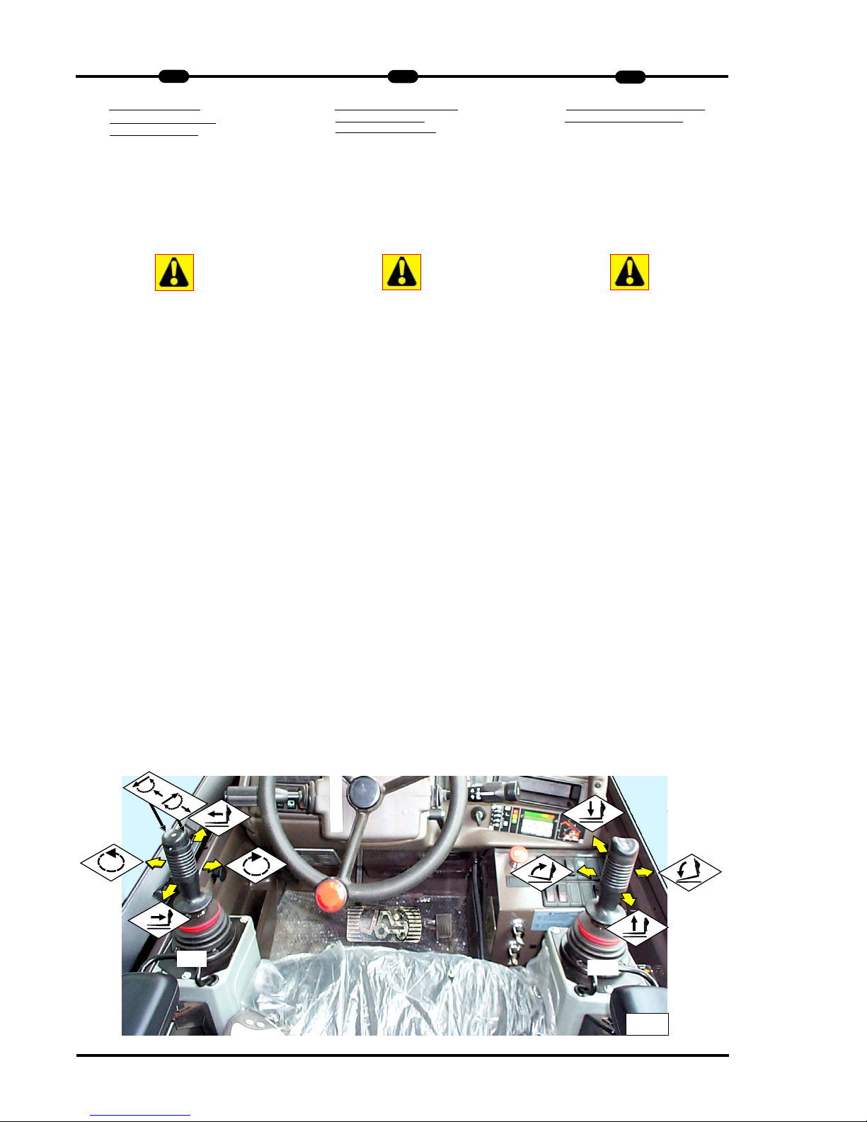
30
2
MRT 1432 - 1635 M
SS
eries
IT
EN
DE
115
5
-
-
ELECTRO-HYDRAULIC
PROPORTIONAL
SERVOCONTROLS
The truck is equipped with two
electrohydraulic servo-controls, one on
the right (15.1) of the operator and one
on the left (15.2), both on the arms of
the driving seat to guarantee better control and comfort.
A microswitch ensures these controls
may only be used when the operator is
sat on the seat.
Servocontrol 15.1
Can operate two double-acting mouvements simultaneously: load lifting and
fork tilting.
To lift the load, pull the lever back.
To lower the load, push the lever
forward.
To tilt the fork forward, push the lever to
the right.
To crowd the forks back, push the lever
to the left.
Servocontrol 15.2
It can operate three double-acting
mouvements simultaneously: Telescopic
boom extension, turret rotation and
optional.
To extend the telescopic boom, push the
lever forward.
To retract the boom, pull the lever back.
To rotate the turret clockwise, push the
lever to the right.
To rotate the turret counter-clockwise,
push the lever to the left.
To operate the optional, push the
rocking button on top of the lever to the
right or left.
115
5
--
ELEKTROHYDRAULISCHE
SERVOSTEUERUNGEN
Der Teleskoplader ist mit zwei elektrohydraulischen Servosteuerungen
ausgestattet, eine rechts (15.1) vom
Bediener und eine links(15.2),
beide sind auf den Armlehnen des
Sitzes angebracht, um eine bessere
Kontrolle und einen höheren Komfort zu
gewährleisten.
Die Bedienfunktionen werden erst dann
freigeschaltet (über einen Mikroschalter
in der Sitzfläche), wenn der Fahrer auf
dem Sitz Platz genommen hat.
Servosteuerung "15.1"
besitzt 2 Funktionen:
"A" Hubfunktion
"B" Neigefunktion
Um die Last anzuheben, den Joy - Stick
nach hinten ziehen.
Um die Last abzusenken, den Joy Stick
nach vorne drücken.
Um die Funktion Neigen zu aktivieren,
den Joy - Stick nach rechts oder links
bewegen.
Servosteuerung "15.2"
besitzt 3 Funktionen :
"A" Ausfahren des Teleskop
"B" Rotation und Zusatzhydraulik
Um den Teleskop auszufahren den Joy Stick nach vorne drücken.
Um den Teleskop eizufahren den Joy Stick nach hinten ziehen.
Funktion Rotation im Uhrzeigersinn den
Joy - Stick nach recht drücken.
Rotation gegen den Uhrzeigersinn den
Joy - Stick nach links drücken.
Die Zusatzhydraulik wird über einen
Drucktaster auf dem rechten Joy - Stick
gesteuert, jedoch muß der Schalter für
die Zusatzhydraulik (Bild 18) zuvor entsprechend eingestellt werden.
Siehe Punkt 15.3
115
5
--
SER
VOCOMANDI
ELETTROIDRAULICI
PROPORZIONALI
Il carrello è dotato di due servocomandi
elettroidraulici uno alla destra (15.1)
dell' operatore e uno alla sinistra (15.2)
entrambi sui bracciali del sedile per
garantire un migliore controllo e
comfort.
Solo quando l’operatore si siede sul
sedile, abilita, tramite un
microinterruttore
presenza uomo, i comandi dei
manipolatori.
Servocomando 15.1
Può azionare simultaneamente due
movimenti a doppio effetto: sollevamento del carico e inclinazione delle forche.
Per sollevare il carico tirare indietro la
leva.
Per abbassare il carico spingere la leva
in avanti .
Per far inclinare la forca verso il basso
spingere la leva verso destra.
Per inclinare verso l’alto la forca spingere la leva a sinistra.
Servocomando 15.2
Può azionare simultaneamente tre
movimenti a doppio effetto: Sfilo del
braccio telescopico; rotazione della torretta e comando optional.
Per sfilare il braccio telescopico spingere la leva in avanti.
Per far rientrare il braccio tirare indietro
la leva.
Per far ruotare la torretta in senso orario spingere la leva verso destra.
Per far ruotare la torretta in senso
antiorario spingere la leva verso sinistra.
Per comandare l'optional spingere sulla
destra o sinistra del pulsante basculante situato sopra la leva.
15.2
15.1
15
Page 99

MRT 1432 - 1635 M
SS
eries
IT
EN
DE
2
31
2
1155..3
3 - OPTIONAL SELECT
OR AND
PLATFORM CONTROL
It selects the function of the rocker button
“P” on servocontrol "15.2" (LEFT).
When the selector is in position A, the
rocker button on servocontrol "15.2"
(LEFT) controls a hydraulic accessory (if
present).
For further control information (pos. B/C)
see the specific “Basket user manual”.
1155..4
4
--
CONTROL SWITCH
OPTIONAL EXCLUSION
Select the function of the rocker button
“P” on serve-control “15.2” (LEFT)
Light switch with two positions:
- push “D”, the optional control is not
allowed and the warning light is swit
ched off
- push “E”, the optional control is
allowed and the warning light is
switched on
Use the optional control is only allowed
and the warning light is switched on.
1155..3
3
--
WAHLSCHALTER
ZUBEHÖR
Wählt die Funktion des Drucktasters
“P” auf der Servosteuerung “15.2”
(LINKS) an.
Wenn der Wahlschalter nicht leuchtet
(Stellung A),steuert der Drucktaster die
Zubehörteile (falls vorhanden).
Über die Funktionen (pos. B/C) siehe.
“Bedienungsanleitung für die
Arbeitsplattform”.
1155..4
4
--
WAHLSCHALTER
ZUSATZHYDRAULIK
Steuert die Funktion des Kippschalters
“P” auf der Servosteuerung “15.2”
(LINKS) Der Schalter verfügt über zwei
Schaltstellungen:
- in der Stellung “D” ist die
Zusatzhydraulik deaktiviert und die
Kontrollleuchte ist aus;
- in der Stellung “E” ist die
Zusatzhydraulik aktiviert und die
Kontrollleuchte leuchtet.
Das Anbaugerät kann nur bei aktivierter
Zusatzhydraulik verwendet werden.
1155..33
-
- SELETTORE OPTIONAL
E
COMANDO CESTELLO
Seleziona la funzione del pulsante
basculante “P” sul servocomando
"15.2" (SINISTRO).
Quando il selettore è in posizione A il
pulsante basculante del servocomando
"15.2" (SINISTRO) comanda un eventuale accessorio idraulico (se presente).
Per ulteriori informazioni di comando
(pos. B/C) vedere sul “Manuale d'utilizzo cestello” specifico.
1155..4
4
--
INTERRUTTORE COMANDO
ESCLUSIONE OPTIONAL
Seleziona la funzione del pulsante
basculante “P” sul servocomando
“15.2” (SINISTRO)
L’interruttore luminoso ha 2 posizioni :
- premendo in “D”, il comando optional
é disabilitato e la spia luminosa è
spenta;
- premendo in “E”, il comando optional
é abilitato e la spia luminosa è accesa.
Solo dopo avere abilitato il comando
optional è possibile l’utilizzo del
accessorio.
15.3
15.4
D
E
15.2
P
Page 100

32
2
MRT 1432 - 1635 M
SS
eries
IT
EN
DE
Precautions when using optional
Precautions when using optional
“hydraulic locking” equipment.
“hydraulic locking” equipment.
Ensure the locking pins are fully engaged in the quick connection holes to
lock the attachment in place (FIG. 15.5).
The selector 1155..44 page.27 must stay in
position “E” to prevent accidental release of the attachment whilst operating.
If the attachment has hydraulic quick
release couplings carry out the following
procedure:
- stop the engine
- disconnect the hydraulic locking hose
fittings (FIG. 15.6) and stow them
away (ref. 1 Fig. 15.7)
- connect the quick release couplings.
(ref. 2 Fig. 15.7)
VVorsicht
orsicht
smaßnahmen bei
smaßnahmen bei
Ausrüstung mit
Ausrüstung mit
"Zusatzhydraulikblock"
"Zusatzhydraulikblock"
Zur Verriegelung des Anbaugerätes
müssen die Verriegelungsbolzen vollständig aus den Bohrungen an der
Schnellbefestigung herausragen.
Der Wahlschalter 1155..44 Seite 27 muss
sich in Stellung "E" befinden, damit das
Anbaugerät beim Arbeiten nicht versehentlich entriegelt werden kann.
Sollte das angebaute Gerät mit hydraulischen Anschlüssen versehen sein, ist
wie folgt vorzugehen:
– Antriebsmotor abstellen und ca. 1
Minute warten,
– Hydraulikanschlüsse vom
Zusatzhydraulikblock abkoppeln
(ABB.
15.6) und in den entsprechenden
Kupplungshalterungen aufbewahren
(Nr. 1, ABB. 15.7),
– Schnellkuppler des Anbaugerätes an
die Schnellverschlüsse anschließen
(Pos. 2, ABB. 15.7).
Precauzioni da osservare se la
Precauzioni da osservare se la
macchina è dot
macchina è dotatat
a del
a del
“Blocco accessori idraulico”
“Blocco accessori idraulico”
I perni di bloccaggio devono fuoriuscire
completamente dai fori dell’attacco rapido per bloccare l’accessorio (FIG. 15.5).
Il selettore 1155..44 pag.27 deve rimanere
in posizione “E” per evitare di sbloccare
accidentalmente l’accessorio durante il
lavoro.
Se poi l’accessorio montato è provvisto
di raccordi idraulici procedere come
segue:
- arrestare il motore termico
- scollegare i raccordi idraulici del blocco accessori idraulico (FIG. 15.6) e
alloggiarli negli appositi porta innesti
(rif. 1 FIG. 15.7)
- connettere i raccordi rapidi dell’acc’essorio montato sull’attacco rapido (rif. 2
FIG. 15.7)
15.5
15.6
2
1
15.7
 Loading...