

Page 1
MAINTENANCE INSTRUCTIONS
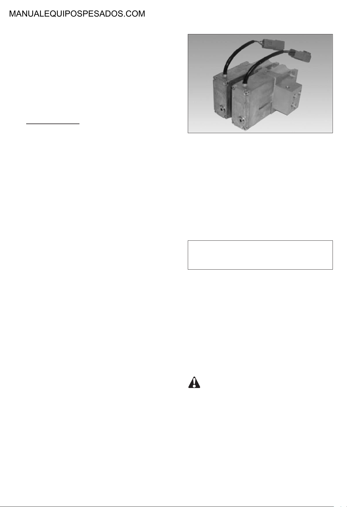
ELECTROHYDRAULIC ACTUATION
MODULE
TYPE EMS
MAINTENANCE
Type : electrohydraulic actuation module EMST = EMSP
SUMMARY
1. Introduction
1.1 Foreword
1.2 Safety instructions
2. Troubleshooting
3. Fondamental rules
3.1 General information concerning electrohydraulic actuation module connection
4. Removal / installation of electrohydraulic
actuation module
4.1 General recommendations
4.2 Removal of a single electrohydraulic actuation module
4.3 Removal of one of several electrohydraulic
actuation modules assembled together
4.4 Electrohydraulic actuation module assembly
4.5 Removal / disassembly of the electrohydraulic transformation stage
5. Removal / assembly of connecting flange and
filter
5.1 Connecting flange removal / assembly
5.2 Filter replacement
6. Neutral position adjustement
1. INTRODUCTION
1.1 - Foreword
It is recommended that only qualified personnel perform
the installation, connection and maintenance of this device, and that all operations be carried out in compliance
with the technical standards in force and the cleanliness
regulations specific to this type of installation.
To ensure maximum performance and safety during
maintenance operations we advise you to
READ THIS MANUAL THOROUGHLY
All informations, illustrations, instructions and characteristics contained in this document are based on the
latest product information available at the time of publication. In its attempts to maintain a high-quality product,
MANITOU reserves the right to make design or technical
modifications at any time and without prior notification.
1.2 - Safety instructions
Please pay a particular attention to the signals of the
safety alertsand special instructions in this manual. They
are indicated in the following manner :
Indicates informations or instructions which
must be followed to guarantee your safety
during operations.
CAUTION : WARNING AGAINST POSSIBLE
EQUIPMENT DAMAGE.
7. Start-up procedures
NOTE : Useful information.
14
Page 2

MAINTENANCE INSTRUCTIONS - Troubleshooting
Observed problems Probable cause
Absence of movement on all
the proportional functions.
Absence or defect of
movement on a proportional
function.
1. Supply voltage insufficient. Check minimum supply
2. Pilot pressure insufficient. Verify the supply pressure of
3. Sealing of the protection
filter of the proportional
controls.
1. Absence of signal of the
proportional control of the
distributor.
2. Signal defect of the proportional control of the distributor.
Additional verifications Solutions
voltage 9V of the proportional
control unit.
the pilot circuit of the
proportional control units
minimum 15 bar.
Clean the filter. Remove filter of the hydraulic
supply unit
(page 22).
Check the signal of the manipulator towards the proportional control units.
Value = 2.5 volts if manipulator knob is at neutral.
Ensure that the signal voltage
comprises of between 1 and
4 volts while using the control
knob of the manipulator.
Verify the connections and
clusters between proportional
control unit and manipulator.
If OK, change the manipulator.
If value outside of limits,
change the manipulator.
Untimely movement with proportional control of the manipulator in neutral.
Sudden or irregular movement on all the proportional
functions.
Sudden or irregular movement on a single proportional
function.
Sudden or irregular movement in a single direction on
a proportional function.
3. Insufficient voltage of the
proportional control units of
the distributor.
Signal defect of the proportional controls of the manipulator.
Protection filter partially sealed.
Looking or jamming of the
position sensor of the proportional control unit.
Looking or jamming of the
pilot drawer of the proportional control unit.
Verify control voltage 5 volts
provided by the proportional
control units to the manipulator.
Check the signal of the manipulator towards the proportional control units.
Value = 2.5 volts if manipulator knob is at neutral.
Clean the filter. Remove filters of hydraulic
If voltage nil or insufficient,
replace the proportional
control unit
(pages 17, 18, 19).
Verify the connections and
clusters between proportional
control unit and manipulator.
If OK, change the manipulator.
supply unit
(page 22).
Replace the proportional
control unit (pages 17, 18,
19).
Replace the proportional
control unit (pages 17, 18,
19).
15
Page 3

MAINTENANCE INSTRUCTIONS - Troubleshooting
Observed problems Probable cause
Symmetry defect of the
control of a proportional function.
Oil leak between two proportional control units.
Oil leak between electrohydraulic and mechanical
interface of the proportional
control units.
Shift of the neutral position of
the position sensor.
Imperviousness defect of the
piping of the pilot circuit between the units.
1. Packing damaged.
2. Pilot pressure too high. Verify that the supply pressu-
Additional verifications Solutions
Adjust the neutral position of
the position sensor
(page 24).
Change the packing
(pages 17, 18, 19).
Change the packing
(page 20).
re of the pilot circuit does not
exceed 35 bar.
3. FONDAMENTAL RULES
3.1 - General information concerning electrohydraulic actuation module connection
Hydraulic
When removing the electrohydraulic actuation module, all openings must be plugged immediately to prevent any contamination of the hydrailic system.
Check the hydraulic installation’s oil quality and filtration capacity during all servicing / maintenance operations.
When replacing the electrohydraulic actuation module, remove the plastic plugs from the openings and lines just before
making the connections.
Do not tighten connectors to a torque greater than that specified in the assembly instructions.
The use of Teflon tape, hemp and joint filler is prohibited.
Hydraulic lines and connections must not be under any strain whatsoever.
Electric
All along the operations, pay attention not to damage the cables and electrical connections.
Check that there is no residual voltage across the cables and electrical connections.
16
Page 4

MAINTENANCE INSTRUCTIONS
4. REMOVAL / INSTALLATION OF THE ELECTROHYDRAULIC ACTUATION MODULE
4.1 - General recommendations
CAUTION : BEFORE REMOVING THE CONTROL BACK FROM THE MACHINE, THE BLOCK AND ITS SURROUN-
DINGS MUST BE THOROUGHLY CLEANED (NOTE: DO NOT DIRECT THE JET OF A PRESSURE WASHING UNIT
DIRECTLY AT THE UNIT).
NO IMPURITIES MUST ENTER THE HYDRAULIC SYSTEM. PLASTIC PLUGS ARE TO BE FITTED ON LINES AND
ORIFICES IMMEDIATELY FOLLOWING THEIR REMOVAL.
Wear protective clothing and use suitable equipment to prevent accidents, particularly concerning the hydraulic fluid.
Use the lifting eyes and suitable handling equipment.
Set all actuators connected to the machine in neutral position (on the ground, at lower limit...) to avoid accidents which
could result from uncontrolled movements of the equipment when the hydraulic system is deconnected.
With the machine off, release the pressure remaining in the system by manipulating all of the distribution spools. This
can be performed by moving the handle in all directions.
17
Page 5
MAINTENANCE INSTRUCTIONS
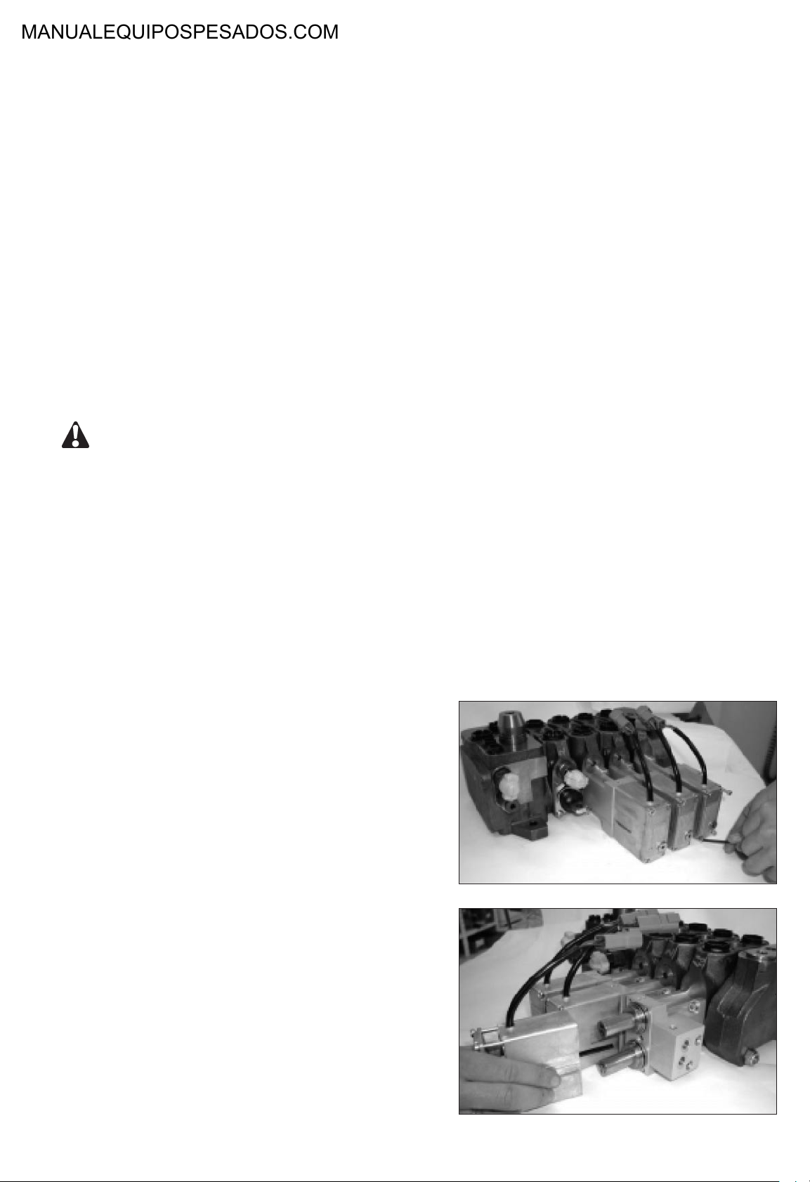
4.2 - Removal of a single electrohydraulic actuation
module
Machine off :
- place all of the machine’s actuators connected
to the control block in neutral position,
- release stored pressure by operating all the
spools (move the handler in all directions).
NOTE : Install a vacuum pump on the tank of the machi-
ne to limit oil leakage when connections are
removed.
After disconnecting the lines from the electrohydraulic actuation module, immediately fit the
sealing plugs. Make sure to collect any possible
oil leakage in a suitable receptacle.
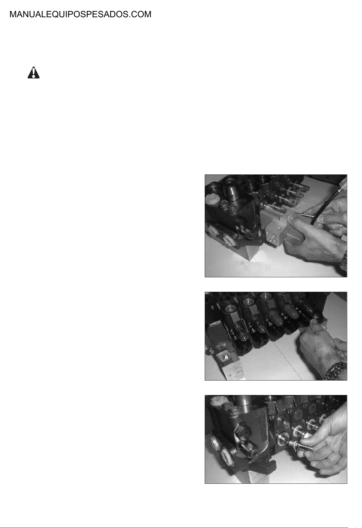
Unscrew the mounting screw using an allen wrench M5.
Reassembly : torque : 15 ± 1 N.m.
Pull the electrohydraulic actuation module backward
parallely to the spool axis in order to release the operation piston.
Remove the cover of spring return system on the opposite side of the spool (see SX14 Maintenance instructions § 6.3).
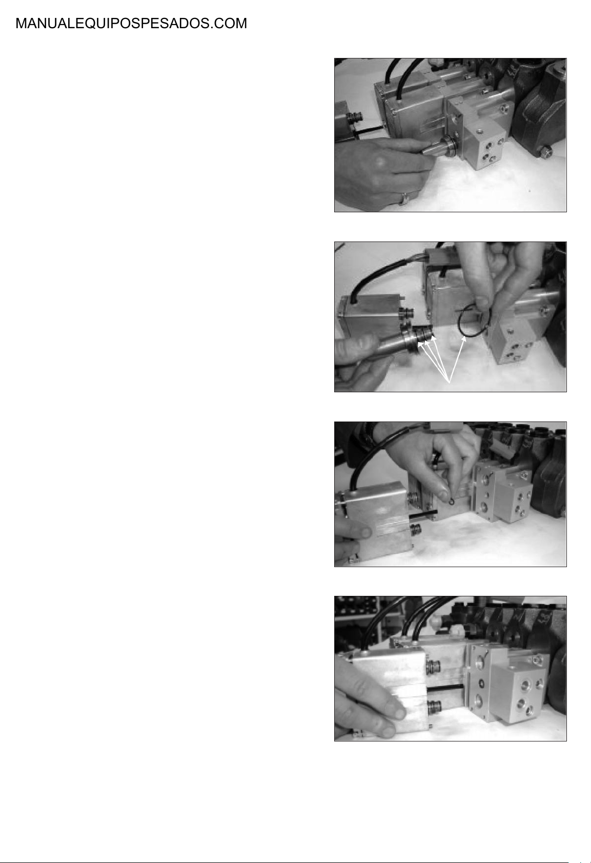
Unscrew the positionning piston from the distributing
spool using a 19mm wrench on piston side and a M5
Allen wrench on spring side.
Reassembly : Apply 2 drops of loctite 242 onto the pis-
ton thread.
torque : 10 ± 1 N.m.
18
Page 6
MAINTENANCE INSTRUCTIONS
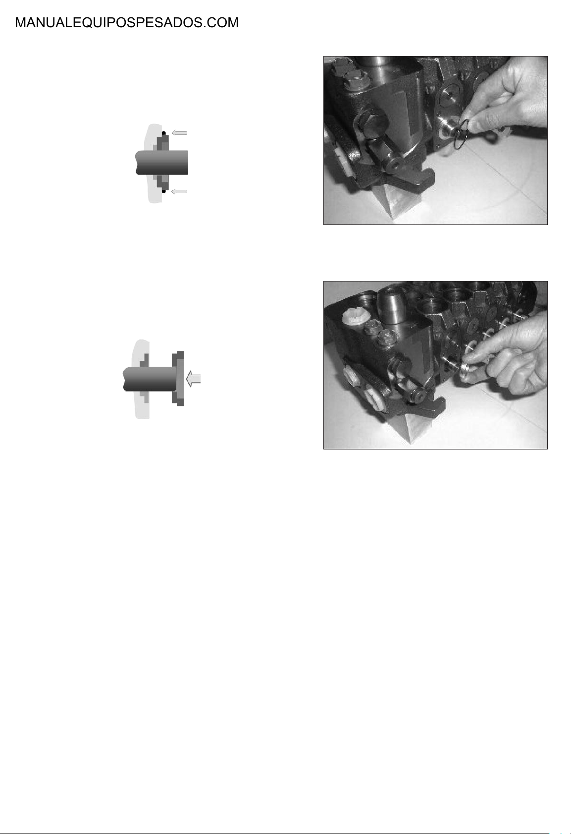
Remove and replace the tightness seal lying between
the actuator and the control valve.
Remove the centering plater.
NOTE : Do not remove the spool from the control valve.
Reassemble in reverse order.
Adjust the neutral position (see § 6).
19
Page 7
MAINTENANCE INSTRUCTIONS
4.3 - Removal of one of several electrohydraulic
actuation modules assembled together
Machine off :
- Place all of the machine’s actuators connected
to the control block in neutral position.
- Release stored pressure by operating all the
spools (move the handler in all directions).
NOTE : Install a vacuum pump on the tank of the machi-
ne to limit oil leakage when connections are
removed.
After disconnecting the lines from the electrohydraulic actuation module, immediately fit the
sealing plugs. Make sure to collect any possible
oil leakage in a suitable receptacle.
To remove an intermediary or terminal electrohydraulic
actuation module, it is required to remove the complete
module assembly.
Unscrew all the mounting screws of each electrohydraulic actuation modules using an Allen wrench M5 (see §
4.2).
Reassembly : torque : 15 ± 1 N.m.
Pull the module assembly backward parallely to the
spool axis in order to release the opertion piston.
Place the modules on a clean and clear surface in order
to pull them apart.
Reassembly :
- Remove and replace the carry-over pipes of the faulty
module.
- Replace the faulty electrohydraulic actuation module.
- Replace all the tighteness seals lying between the
actuators ans their control valve.
- Reassemble in reverse order.
- Adjust the neutral position (see § 6).
20
Page 8
MAINTENANCE INSTRUCTIONS
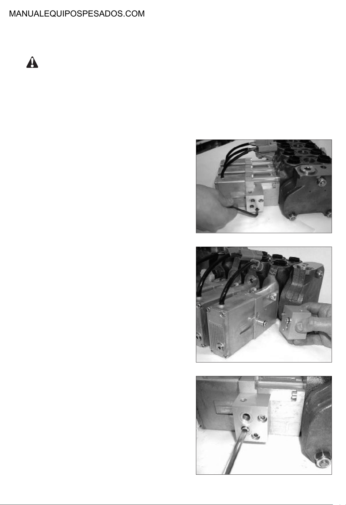
4.4 - Electrohydraulique actuation module assembly
Check the cleanliness of the contact faces prior to reassemble.
Replace the carry-over pipes that have been removed.
Replace the O-ring between the electrohydraulic actuation module and the control valve element.
Reassemble the module in the reverse order of operations described in § 4.2 and 4.3.
4.5 - Removal / disassembly of the electrohydraulic
transformation stage
NOTE : The electrohydraulic actuation module does not
need to be removed to perform this operation.
Machine off :
- Place all of the machine’s actuators connected to the control block in neutral position.
- Release stored pressure by operting all the
spools.
Once correctly installed, the unit can be placed into
operation :
- Check the condition of line connector seals.
- Check the condition of electric wires.
- Connect the lines to the block as per the connecting
diagram and tighten to the torque specification
(refer to the table in the Data sheat).
- Ensure that hoses are not twisted nor rub.
NOTE : Install a vacuum pump on the tank of the machi-
ne to limit oil leakage when connections are
removed.
After disconnecting the lines from the electrohydraulic actuation module, immediately fit the
sealing plugs. Make sure to collect any possible
oil leakage in a suitable receptacle.
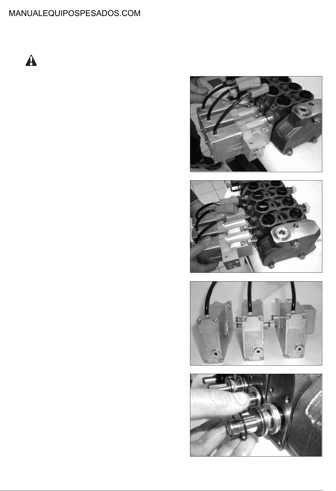
Unscrew the 4 mounting screws using an allen wrench
M3.
Reassembly : torque : 3 to 3,5 N.m.
Remove the electrohydraulic transformation stage by
gently pulling it backward parallely to the spool axis until
the rod of the position sensor is completly extracted.
NOTE : The removal of the 4 mounting screws of the
electrohydraulic transformation stage releases
the PCB tightened protecting cover. Avoid all
risk of pollution, humidification or impacts on
electronics and hydraulics parts during the
operations.
21
Page 9
MAINTENANCE INSTRUCTIONS
Remove one or both electrohydraulic valve(s).
NOTE : This operation is to be performed only in the
case of an external leakage noticed around the
tightness seal between the valve and the housing.
Reassembly :
- replace the external tightness seals on the valves
- fit the valve(s) into its (their) housing(s).
Replace the external tightness seal of the rod (or sensor
O-ring).
NOTE : Place the sensor O-ring in its groove on the
mechanical interface side prior to assembly.
Reassemble the electrohydraulic transformation stage in
reverse order.
Joints d'étanchéité
22
Page 10
MAINTENANCE INSTRUCTIONS
5. REMOVAL / ASSEMBLY OF CONNECTING
FLANGE AND FILTER
Machine off :
- Place all of the machine’s actuators connected to the control block in neutral position.
- Release stored pressure by operating all the
spools.
NOTE : Install a vacuum pump on the tank of the machi-
ne to limit oil leakage when connections are
moved.
After disconnecting the lines from the electrohydraulic actuation module, immediately fit the
sealing plugs. Make sure to collect any possible
oil leakage in a suitable receptacle.
5.1 - Connecting flange removal / assembly
Unscrew the 2 mounting screws using an allen wrench
M5.
Reassembly : torque : 11 ± 1 N.m.
Remove the connecting flange. Pull the connecting flange backward parallely to the screw axis in order to release the carry-over pipes.
Reassemly :
- Replace carry-over pipes.
- Reassemble parts in reverse order.
5.2 - Filter replacement
Unscrew the filter in the port P using a flat screw driver.
Reassembly : hand tight the filter in port P.
23
Page 11
MAINTENANCE INSTRUCTIONS
6. NEUTRAL POSITION ADJUSTMENT
NOTE : To perform this operation, the control block does
not need to be removed from the machine, nor
the electrohydrauic actuator module from the
control valve.
Machine off :
- Place all of the machine’s actuators connected
to the control block in neutral position.
- Release stored pressure by operating all the
spools (move the handler in all directions).
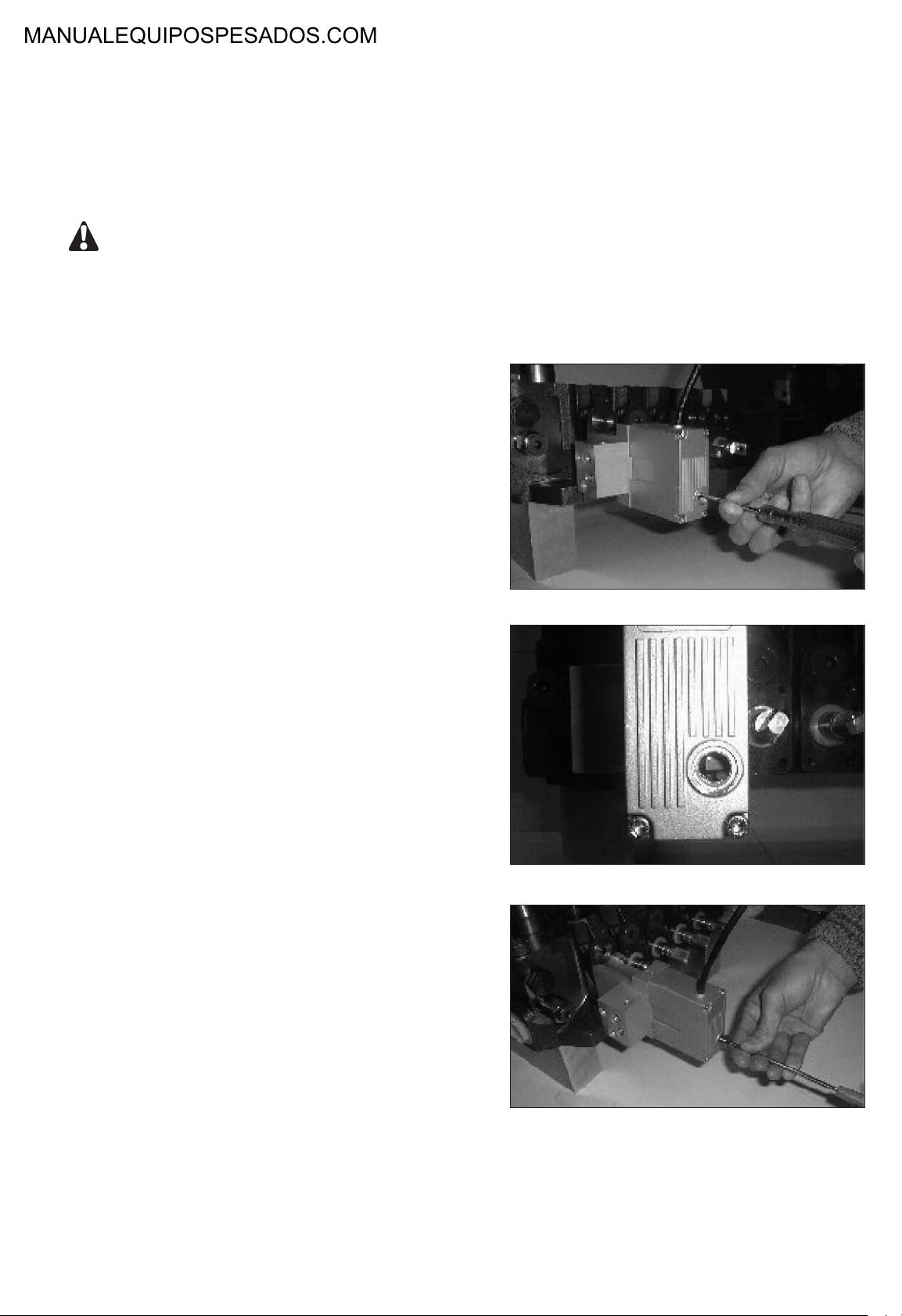
Locate and remove the inspection plug on the lower side
of the actuation module rear cover.
Switch on the electrical power (12VDC or 24VDC) only
(no hydraulic power).
The assistance pressure of 35 bar must absolutely be
decompressed.
Locate the adjusting trimmer inside and the green LED
underneath. The green LED will turn on by the time the
”mechanical zero” of the spool matches the ”electrical
zero” of the electronic setup.
Using a flat and thin screwdriver, turn the trimmer clockwise or counterclockwise until the green LED turns on.
24
Page 12

MAINTENANCE INSTRUCTIONS
7. START UP PROCEDURES
Machine off :
- Place all of the machine’s actuators connected to the control block in neutral position.
- Release stored pressure by operating all the spools. Make sure that the remote control is switched off
while starting up the engine and before the hydraulic pump is engaged.
Start up the engine and engage the oil pump. Turn on the remote control system.
CAUTION
THE ELECTROHYDRAULIC PROPORTIONAL SYSTEM IS DESIGNED AND QUALIFIED FOR LOW TEMPERATURE
OPERATION UP TO -40°C. FOR OIL TEMPERATURE LESS THAN -15°C, ACTUATORS MOVEMENTS MAY INITIALLY RESULT SLOW AND JERKY. IT IS STRONGLY RECOMMANDED THAT COLD WEATHER START-UP ARE FOLLOWED BY PROPER OIL HEATING PROCEDURES.
Engage the remote control device and slowly vary the control signal making sure that no external obstacle can be hit in
case of unadverted movements.
In response to a variable signal generated by the remote control device, the selected machine’s function must smoothly
accelerate / decelerate, showing good stability and repeatability.
When one remote control function at a time is engaged, only the corresponding machine function must respond, while all
the other machine functions remain at rest.
25
Page 13
50
Transmission control and adjustment
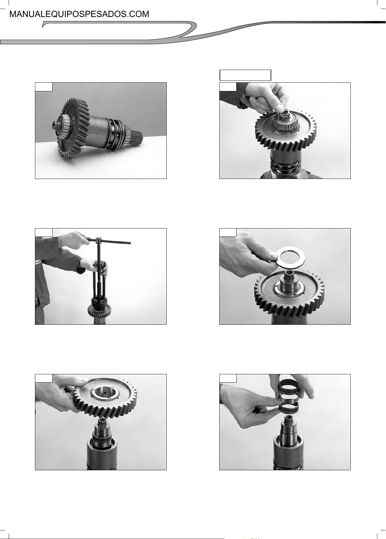
6 - SPRUNG-ON 4 WHEEL DRIVE DIS-ASSEMBLY AND RE-ASSEMBLY
DIS-ASSEMBLY
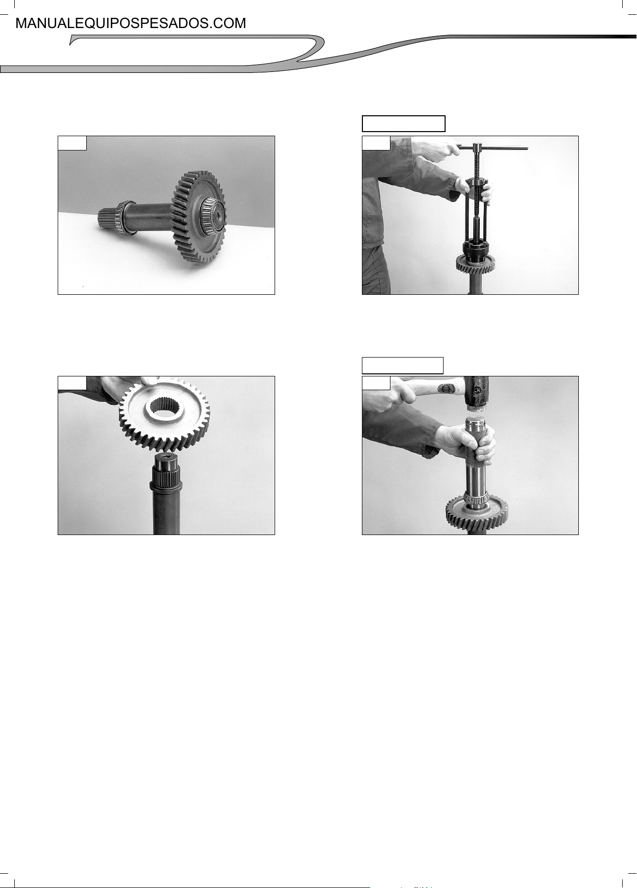
6-1
The sprung on 4 wheel drive assembly.
6-2
Position the shaft in a soft jawed vice
and remove the sealing ring.
6-3
Using the appropriate bearing puller
remove the rear bearing.
6-5
6-4
Remove the thrust washer.
6-6
Remove the 4 wheel drive gear.
Remove the two needle bearings and
spacer.
(01/07/2008)
Page 14
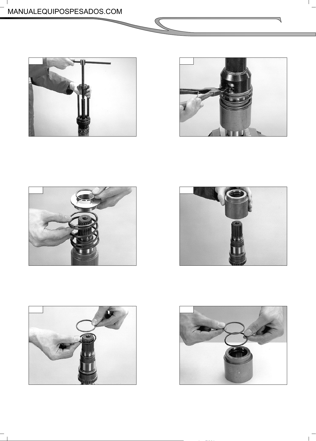
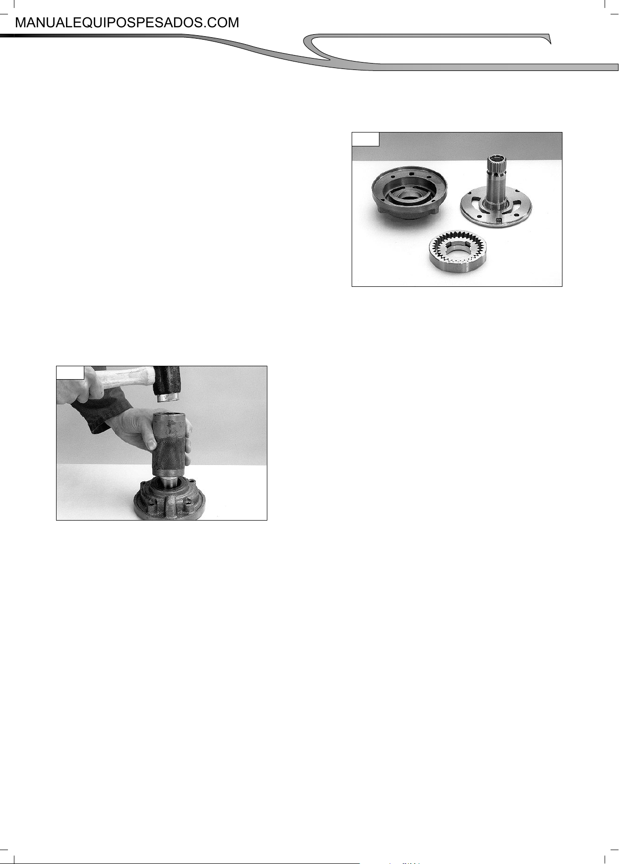
6-7
Invert the shaft and using the appropriate
bearing puller remove the front bearing.
Transmission control and adjustment
6-8
Using the appropriate tool compress the
spring and release the circlip.
51
6-9
Remove the circlip, retainer, and spring.
6-11
6-10
Remove the piston drum assembly.
6-12
Remove the piston seal and «O»ring from
the shaft and discard.
(01/07/2008)
Remove and discard the piston seal and
«O»ring from the piston drum.
Page 15
52
Transmission control and adjustment
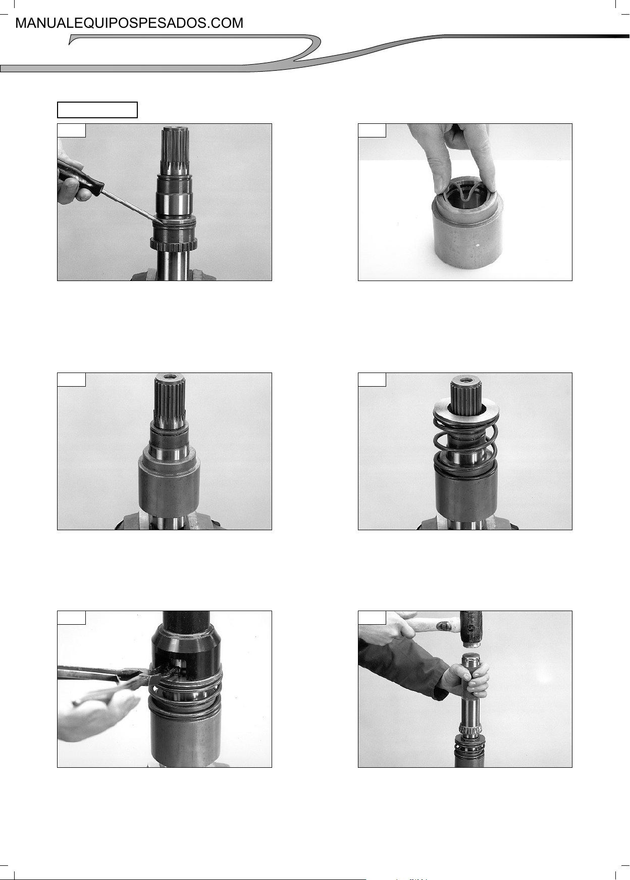
RE-ASSEMBLY
6-13
Fit a new «O»ring and sealing ring to the
shaft.
See (fi g. 6-11).
6-14
Fit a new «O»ring and sealing ring into the
piston. Bend the sealing ring into a heart
shape as shown to assist assembly.
6-15
Lubricate the seals with a light grease
and refi t the piston to the shaft.
6-17
6-16
Replace the piston spring and retainer.
6-18
Using the appropriate tool compress the
spring and retainer and refi t the circlip.
Using an appropriately sized tube refi t
the front bearing.
(01/07/2008)
Page 16
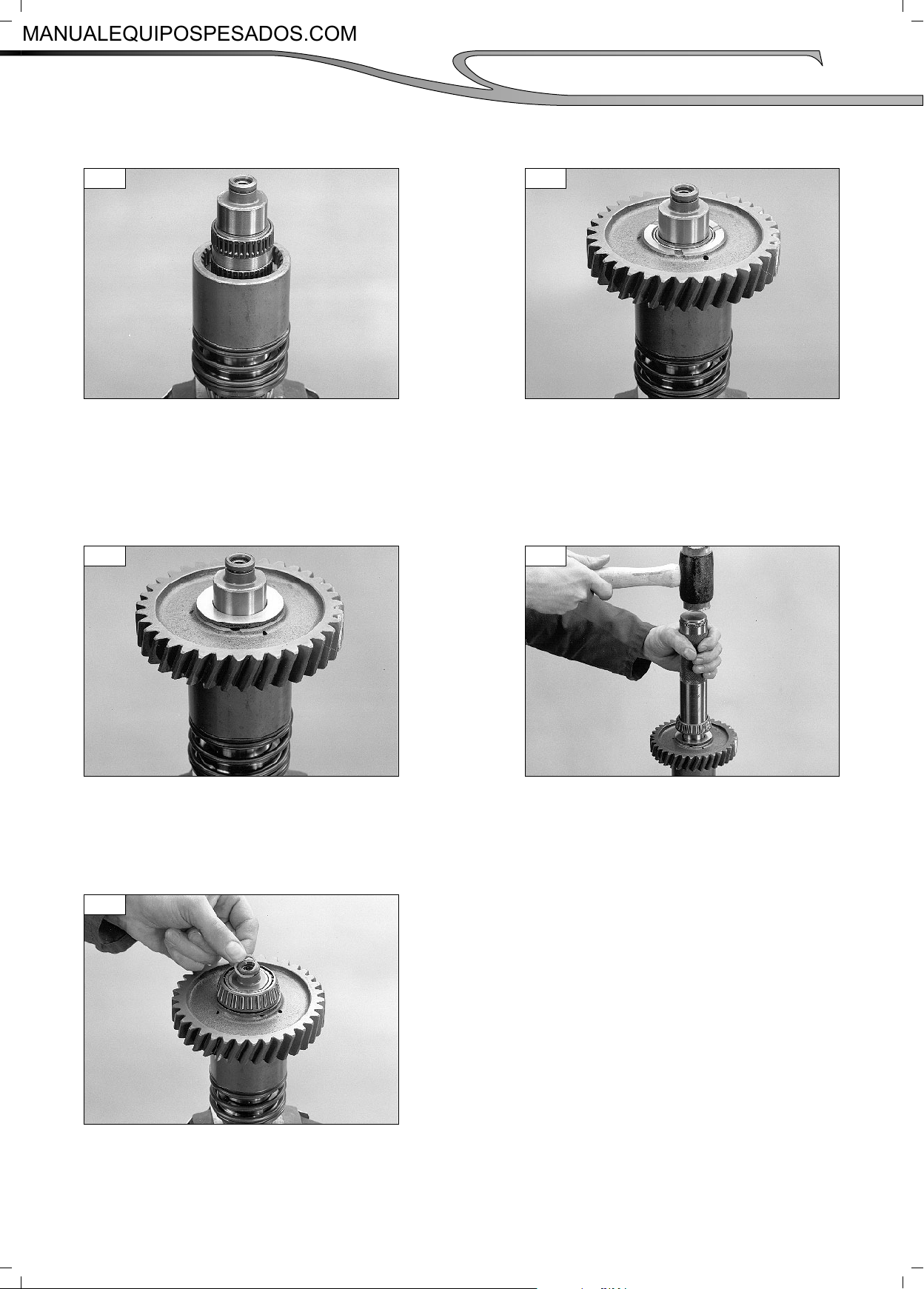
6-19
Invert the shaft and refi t the two needle
bearings and spacer as shown.
Transmission control and adjustment
6-20
Replace the 4 wheel drive gear.
53
6-21
Replace the thrust washer.
6-23
6-22
Using an appropriately sized tube replace
the rear bearing.
Fit a new sealing ring.
(01/07/2008)
Page 17
54
Transmission control and adjustment
7 - PERMANENT 4 WHEEL SHAFT DIS-ASSEMBLY AND RE-ASSEMBLY
DIS-ASSEMBLY
7-1
The permanent 4 wheel drive shaft.
7-2
Using the appropriate bearing puller
remove the front and rear bearings.
7-3
Remove the 4 wheel drive gear.
RE-ASSEMBLY
7-4
Replace the 4 wheel drive gear using
stop threaded product (P / N° 548110),
on the shaft splines . Then using a
suitably sized tube re-fi t the front and
rear bearings.
(01/07/2008)
Page 18
Transmission control and adjustment
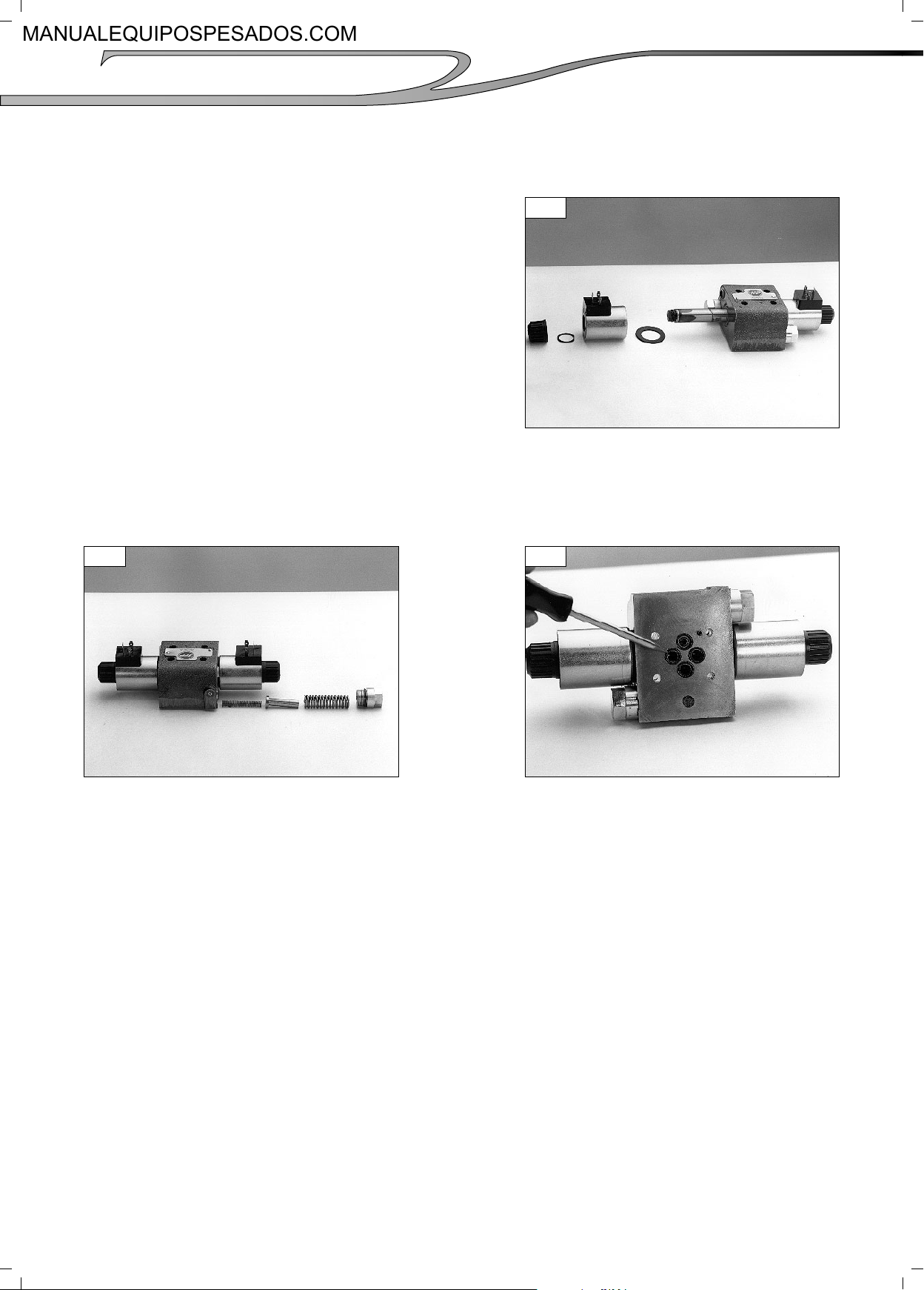
8 - DIS-ASSEMBLY AND RE-ASSEMBLY OF THE OIL PUMP
Note : Individual components of the oil
pump are non serviceable. The pump
may, however, be stripped for cleaning
and examination purposes.
8-1
View showing a dismantled pump
assembly.
55
8-2
The pump oil seal may be replaced using
an approprietely sized tube.
(01/07/2008)
Page 19
56
Transmission control and adjustment
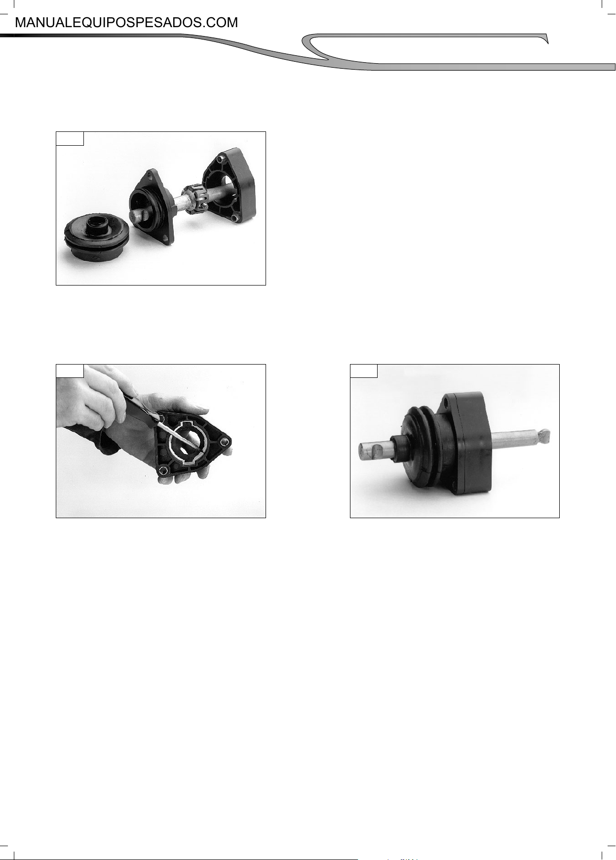
9 - DIS-ASSEMBLY AND RE-ASSEMBLY OF THE VALVE
Nota : Dis-assembly of the control valve
is not generally recommended
as, with the exception of the
solenoids, individual parts are
non serviveable. It may however
be dismantled for cleaning and
examination.
9-1
The retaining nut, coil and washers
removed.
9-2
The modulation components removed.
9-3
There are 4 «O»rings fi tted to the
underside of the valve which may be renewed if necessary.
(01/07/2008)
Page 20
Transmission control and adjustment
10 - GEAR LEVER HOUSING DIS-ASSEMBLY AND RE-ASSEMBLY
10-1
Remove the plastic ties from the rubber
gaiter and pull the assembly apart as
shown.
Nota : Before re-assembly remove all
traces of old sealant from the
joint faces.
57
10-2 10-3
Apply a airtightness product (P / N°
562228) to the sealing face as shown.
Lubricate the ball seating with a light
grease and push the two halves of the
assembly together. Secure the rubber
gaiter with two new plastic ties.
(01/07/2008)
Page 21

58
Transmission control and adjustment
11 - TRANSMISSION RE-ASSEMBLY
Note : All shafts and bearing should be
lubricated with transmission fl uid prior
to assembly.
To prevent possible contamination of
hydraulic parts lint or cotton rags
should not be used.
11-1
4WD VERSION : Position the front case
as shown and using a suitably sized
tube fi t a new 4 wheel drive output shaft
oil seal to a depth of 6mm below the
housing face. Fill the seal lip with light
grease.
11-2
Re-fi t the oil pump assembly and sealing
ring. Tighten 4 bolts to a torque of 1323 Ib / ft. New copper washers must be
fi tted under the bolt heads.
11-4
11-3
If previously removed, replace the two
plug and «O»ring assemblies as shown
and tighten to a torque of 30 to 40 Ibs
/ft.
11-5
Invert the case and then re-fi t the bearing
cups if previously removed.
Using a suitable tool push the inner
detent spring and ball into the case and
secure in place with a dummy plug as
shown. (ø 18 mm, lg. 25 mm).
(01/07/2008)
Page 22

11-6
Dummy plug in place
11-8
Transmission control and adjustment
11-7
Replace the countershaft and reverse
idler shaft assemblies.
11-9
59
Slide the 1st / 2nd fork onto the 3rd /
4th rail then refi t the 3rd / 4th shift fork
and tighten the screw to a torque of 13
to 18 Ibs / ft. Hold the forks and rail
in place on the output shaft then re-fi t
the complete assembly into the case.
The shift rail should displace the dummy
plug as it enters the bore.
Note : Check that the inner detent spring
and ball have not become displaced and
remove the loose dummy plug from the
case sump.
11-10
Push the interlock ball into the detent
bore.
11-11
Re-fi t the 1st / 2nd shift rail and tighten
the shift fork screw to a torque of 13 to
18 Ibs / ft. Check that the interlock ball
is correctly positioned in between the
two rails.
(01/07/2008)
Replace the outer detent ball and spring.
Tighten the plug to a torque of 30 to 40
Ibs /ft.
Page 23

60
Transmission control and adjustment
11-12
4WD VERSION : Replace the 4 wheel
drive shaft assembly. Lubricate the rear
seal with a light grease.
11-14
11-13
Lubricate the input shaft front and rear
seals a light grease and re-fi t the shaft
assembly into the case.
11-15
Rear case with all shaft assemblies
fi tted.
11-16
Invert the case and replace the shim
packs and bearing cups. The 2mm thick
spacer shim should be fi tted into the
case fi rst, then fi t the remaining shims
followed by the bearing cup. A light
grease may be used to help hold the
cups in the case.
Position the rear case as shown and
using a suitably sized tube fi t a new
output shaft oil seal to a depth of 6mm
below the housing face. Fill the seal lip
with a light grease.
11-17
Re-fi t the rear case, (without sealant at
this stage), and secure with at least 6
equally spaced bolts. When fi tting the
rear case be careful to avoid damaging
the input shaft sealing rings.
(01/07/2008)
Page 24

11-18
Position a D.T.I. on the end of the input
shaft as shown, and using a suitable
pry bar through the side access hole,
measure and note the shaft end fl oat.
11-20
Transmission control and adjustment
11-19
Attach a suitable shimming tool, (with a
12mm thread), to the end of the reverse
idler shaft. Position a D.T.I. as shown,
and using a pry bar lift the shaft, then
measure and note the end fl oat.
11-21
61
Attach a suitable shimming tool, (with
a 12mm thread), to the end of the
countershaft. Position a D.T.I. as shown,
and using a pry bar lift the shaft, then
measure and note the end fl oat .
11-22
4WD VERSION : Attach a suitable
shimming tool, (with a 12mm thread),
to the end of the 4 wheel drive shaft.
Position a D.T.I. as shown, and using a
pry bar lift the shaft, then measure and
note the end fl oat.
(01/07/2008)
Attach a suitable shimming tool, (with
a 12 mm thread), to the end of the
output shaft. Position a D.T.I. as shown,
and using a pry bar lift the shaft, then
measure and note the end fl oat.
Remove the rear case and add or remove
shims as necessary to give .001» to
.003» end fl oat on all shafts.
Repeat steps 11.17 to 11.22 until all
shaft end fl oats are correct.
Page 25

62
Transmission control and adjustment
11-23
Replace the 4 «O»rings in the front case.
(There are only 3 fi tted on the 2 wheel
drive model).
11-24
Re-fi t the rear case using an approved
liquid gasket Taking care not to damage
the input shaft sealing rings. Tighten the
17 bolts to a torque of 33 to 47 Ibs /
ft.
11-25
Replace the shaft end plug and «O»ring
assemblies. Note the special breather
plug es fi tted in the reverse idler position.
Tighten to a torque of 30 to 40 Ibs / ft.
11-27
11-26
Fit a new expansion plug to the shimming
access hole using an approved
sealant. Stop threaded product (P / N°
562227).
11-28
Replace the output yoke, «O»ring, washer
and bolt. Then tighten to a torque of 50
to 65 Ibs / ft.
4WD VERSION : Replace the spacer,
4WD yoke, «O»ring, washer and bolt.
Then tighten to a torque of 50 to 65 Ibs
/ ft.
(01/07/2008)
Page 26

11-29
Re-fi t the cold start ball, spring and
housing. Then tighten to a torque of 34
to 44 Ibs / ft.
11-31
Transmission control and adjustment
11-30
Lubricate the seals with transmission
fl uid then re-fi t the pressure regulator
valve and tighten to a torque of 34 to 44
Ibs / ft.
11-32
63
Lubricate the seals with transmission
fl uid then re-fi t the converter regulator
valve and tighten to a torque of 17 to 22
Ibs / ft.
11-33
Ensure the 4 «O»ring are in place then refi t the control valve assembly and tighten
the 4 caps crews to a torque of 5.0 to
6.3 Ibs / ft. The valve can only be fi tted
one way round as it is located by a small
dowel pin.
Re-fi t the temperature sender and tighten
to a torque of 15 to 20 Ibs / ft.
11-34
Re-fi t the strainer, spacer, «O»ring and
cover plate. Then tighten the two screws
to a torque of 13 to 23 Ibs / ft.
(01/07/2008)
Page 27

64
Transmission control and adjustment
11-35
Re-fi t the drain plug and «O»ring assembly.
Tighten to a torque of 25 to 40 Ibs / ft.
11-36
Re-fi t the 4th gear lock out screw, (when
this feature is not required a shorter
blanking screw is fi tted). On some
applications an additionnal sealing plug
may be fi tted.
11-37
Apply a bead of RTV joint compound (P /
N° 562228) to the gear case as shown.
11-39
11-38
Re-fi t the gear lever assembly and tighten
the three bolts to a torque of 12 to 18
Ibs / ft.
11-40
Re-fi t the fi lter housing and gasket.
Tighten the two bolts to a torque of 33
to 47 Ibs / ft.
Lubricate the seals with a light grease
and screw on a new oil fi lter.
(01/07/2008)
Page 28

11-41
4WD VERSION : Lubricate the seals with
a light grease and re-fi t the 4 wheel drive
solenoid spool. Tighten to a torque of 15
to 20 Ibs / ft.
11-43
Transmission control and adjustment
11-42
4WD VERSION : Re-fi t the 4 wheel drive
solenoid coil and nut. Tighten to a torque
of 4 Ibs / ft maximum.
65
4WD VERSION : If previously removed
re-fi t the 4 wheel drive clutch supply
pipe, apply air tightness product (P / N°
62175) to threads and thighten nuts to
a torque of 5 to 7.5 Ibs / ft.
(01/07/2008)
Page 29

66
Transmission control and adjustment
INSTALLATION AND ADJUSTEMENT OF SPEED PROBE
Align a gear tooth directly in the centre of the threaded sensor opening. screw in by hand. The
speed sensor (A) until it makes contact with the tooth (C). Unscrew the speed sensor by one half
to three quarters of a turn (in an anti-clockwise direction).
This will set the gap (B) between the speed probe and the gear tooth to between 0,71 & 1,06 mm.
Tighten the lock nuts to a torque of between 2,5 to 5 Nm after adjustment is completed
(01/07/2008)
Page 30

TEST PROCEDURE
Transmission control and adjustment
67
(01/07/2008)
Page 31

OPERATING AND SETTING OF THE LONGITUDINAL STABILITY ALARM
OPERATOR
Switch the machine
on
Engine turning over
To position "0", machine :
- Stable (no movement)
- With no attachments
- Jib raised to max., telescope
retracted
- On wheels (stabilizers raised)
- Wheels aligned
- On machines fitted withtilting
corrector.
- Frame an horizontal position.
Press for 2 s the adjust button
located at the back of the unit
(see diagram 2)
Press the "STOP
BUZZER" button
To position "MAX":
Jib on horizontal position.
Take the machine's rated load,
position it at max. startup as
indicate on load chart minus
100mm.
UNIT VISUAL DISPLAY AUDIO SIGNAL
All the LEDS are on
Start of setting
2 yellow LEDS and 2
Enter set mode
"O" setting saved
green LEDS in the
middle flash alternately
2 green LEDS at the bottom
remain on
2 red LEDS at the top remain
on
2 yellow LEDS and 2
green LEDS in the
middle flash alternately
5 beeps indicate that the setting
has been saved
Press the "TEST"
button
Check the setting against the load
chart : put the rated load at max.
startup
setting
conforms
to load
chart
YES
NO
"MAX" setting saved
setting
conforms
consistency
"MAX" and "0"
YES
The unit automatically leaves the set
position the LEDS stop coming on
End of setting
Operator starts setting over
again
NO
The unit returns to the
"locked" position
All the LEDS are on, with
no buzzer ignition on
The LEDS come on up to
the first red LED
5 beeps indicate that the setting
has been saved
Operator starts setting over
again
A continuous 2s beep
indicates to the operator that
the settings have been taken
into account and that the unit
is passing automatically into
the normal operation position
Stick on the other part of the
"SESALY" sticker to seal the setting
(see diagram 2)
The operator can put the truck in the
desired position
3
Page 32

1 - This setting must be made with the rear axle assembly at a stable temperature.
Do not carry out after braking tests as the temperature difference between the
axle assembly and the gauge would disturb the setting.
2 - Before setting the unit, it is important to operate the machine for placing the strain
gauge (for example, when testing the machine, in which case make sure to
comply with point N° 1).
3 - Last checking of setting must be done before forwarding the machine
WARNING
2 red LEDS
2 yellow LEDS
4 green LEDS
DIAGRAM 1
1 red LED
DIAGRAM 2
Place the sticker after setting and
conformity checks
(To change at each setting)
Set button clearance hole
(tool Ø 2, min. length 40)
4
Page 33

2 red LEDS
SAFETY SYSTEM
Test switch
Sound alarm signal light off
2 yellow LEDS
4 green LEDS
Sound alarm
off switch
Power supply connector +
aggravating movements cut-off
signal output
Connection to the strain
gauge
adjustment microswitch (accessible with a 6 mm
male hexagonal wrench)
5
Page 34

INSPECTION PROCEDURE FOR THE LONGITUDINAL STABILITY ALARM STRAIN GAUGE
Connector engineering :
+ power supply red wire / contact N° 1
- power supply and PT 100 brown wire / contact N° 2
+ measurement yellow wire / contact N° 3
- measurement green wire / contact N° 4
PT 100 blue wire / contact N° 5
Shielding white / contact N° 6
Description of the connectors of strain gauge.
Shielding 6
PT 100 5
Measurement - 4
+ power supply 1
- power supply 2
Measurement + 3
Prior to any electrical inspection, carry out a visual check on the state of the gauge and its
connections.
6
Page 35

Electrical Inspection
Disconnect the gauge from the electrical circuit.
Use a multimeter to take the following
measurements :
(Fig.A)
- Measure the impedance between A+ and A- =
Z power (power supply impedance)
Values : 300Ω≤Z power ≤ 400Ω
(Fig.B)
- Measure the impedance between M+ and M- =
Z meas. (measuring system impedance)
Values : 300Ω≤Z power ≤ 400Ω
(Fig.C)
- Measure the impedance between A- and PT
100 = Z PT100
Values : 101Ω + 0.39xT
T corresponds to the gauge temperature.
Example : T=20°C then
Z PT 100 = 101Ω + 7.8Ω = 109Ω
Fig.A
Fig.B
Between A+ and A-
350 Ω
off 500Ω
5 KΩ
Between M+ and M-
350 Ω
off 500Ω
5 KΩ
(Fig.D)
-
Measure the impedance between A+ and
shielding : Zbl
Zbl > 30 MΩ (infinite resistance or open
circuit)
(Fig.E)
- Measure the impedance between A+ and the
machine frame : Z frame
Z frame > 30 MΩ (infinite resistance or
open circuit)
Fig.D
Betwen A+ and shielding
l
off 500Ω
5 KΩ
Fig.C
Fig.E
Between A- and PT100
109 Ω
off 500Ω
5 KΩ
Between A+ and Frame
l
off 500Ω
5 KΩ
7
Page 36

8
Page 37

1- MANITOU S.A. AIR CONDITIONING UNIT OPERATING
PRINCIPLE
1.1- GENERAL INFORMATION ON THE MANITOU AIR-CONDITIONING FUNCTION
1 Compressor
2 Condenser
3 Dehydrating
filter
4 Expansion valve
5 Evaporator
6 Blower system
The MANITOU air-conditioning unit is based on the coolant's ability to absorb heat in considerable
quantities when it is subjected to physical changes on being transformed from a liquid state to a gas.
Operating cycle (see diagram) :
The gas coolant, at low temperature and pressure, is sucked in by the compressor which is driven by the
vehicle engine.
The compressor expulses the coolant, still as a gas, at high pressure and temperature, and it goes into the
condenser in this state.
Inside the condenser, the fluid undergoes a physical transformation from a gas to a liquid state, giving off
heat in the process. The warm air which passes through the condenser is evacuated by a dynamic effect
produced by the engine cooling fans. The liquid coolant leaving the condenser crosses the dehumidifying
filter which removes the humidity and solid impurities, then goes on to the expansion valve.
When the liquid is vaporized in the expansion valve, the pressure falls and lowers the temperature in the
evaporator. During its travel through the evaporator, the coolant is physically transformed from a liquid to
a gaseous state and then sent to the compressor. The air which flows over the cold surfaces of the
evaporator is cooled in turn, lowering the temperature in the cab.
This air, which is circulated by an electric blower system is dehumidified because the vapour in the air, is
condensed following contact with the cold walls of the evaporator. This condensation water is collected in
a drainage trap and evacuated outside the machine.
3 / 32
Page 38

Electric skeleton diagram
TC Control panel
BP Bouton poussoir
L Tongue
S Blower
T Thermostat
P1 Low pressure gauge
P2 High pressure gauge
R Relay
EC Compressor clutch
F1 7.5 A fuse
F2 30 A fuse
CONNECTORS
C1 5-way, black AMP MIC IV-TV - Ref. 144 518-2
C2 6.35 x 0.8 mm female connector
C3 90" 6.35 x 0.8 mm female connector
C4 Deutsch Ref. HD10-6-12P
C5 1-way RKG female connector Ref. 920 510
C6 Deutsch Ref. HD16-6-12S-B010
C7 2-way female DT - Ref. 552 459
C8 2-way male DT - Ref. 552 457
C9 2-way male DT - Ref. 552 457
C10 2-way female DT - Ref. 552 459
4 / 32
Page 39

1.2- THE COMPRESSOR
The compressor's job is to pump the coolant leaving the evaporator, in gas phase, at low temperature and
pressure, and compress it into the condensor at high pressure and temperature.
The compressor mechanisms are lubricated with a special oil which is included in the compressor during
manufacture. Part of this lubricant is circulated through the installation by the coolant.
The compressor is driven by the engine via a belt and activated by engaging an electromagnetic clutch.
10 cm3 extra oil PAG SP20 is added to the original quantity to compensate for the length of
the hoses.
A fluorotracer additive, miscible in the oil lubricant, is used to detect leaks in the system
during after sales service operations and this is in the compressor casing.
5 / 32
Page 40

1.3- THE CONDENSER
The condenser is a heat exchanger which condenses the coolant. This arrives in the form of a gas at high
pressure and temperature, and the condenser liquefies it through the fall in temperature caused by the air
passing throught it. The condenser is fitted with easily identified input and output connections. The fluid
arriving as a gas goes in through the large connection and leaves by the small one in liquid form. The
condenser must be supplied with air by the radiator cooling fan which pulses air through it to condense
the fluid.
6 / 32
Page 41

17
INNER TELESCOPING CYLINDER
MT 932 Série B
OUTER TELESCOPING CYLINDER
MT 932 Série B
2
3
5
6
17
POCHETTE DE JOINTS
DICHTUNGSATZ
JUEGO DE JUNTAS
SEAL KIT
SERIE GUARNIZIONE
236 813
7
12 x 2
13
16 x 2
1
1er MONTAGE
1ste MONTAGE
1ro MONTAJE
1st MOUNTING
1mo MONTAGGIO
12
11
19
18
15
14
14
11
10
15
13
12
2ème MONTAGE
2te MONTAGE
2do MONTAJE
2nd MOUNTING
2do MONTAGGIO
2
4
5
6
7
16
16
3
2
3
5
6
17
7
POCHETTE DE JOINTS
DICHTUNGSATZ
JUEGO DE JUNTAS
SEAL KIT
SERIE GUARNIZIONE
236 812
12 x 2
13
16 x 2
1
9
8
1er MONTAGE
1ste MONTAGE
1ro MONTAJE
1st MOUNTING
1mo MONTAGGIO
2ème MONTAGE
2te MONTAGE
2do MONTAJE
2nd MOUNTING
2do MONTAGGIO
12
11
19
18
15
14
14
11
15
16
3
16
4
5
6
7
13
12
10
2
8
9
Page 42

18
TILTING CYLINDER
MLT 630 / 634 Série B
TILTING CYLINDER
MLT 731 Série B
11
12 x 2
13
14
22
15
POCHETTE DE JOINTS
DICHTUNGSATZ
JUEGO DE JUNTAS
SEAL KIT
SERIE GUARNIZIONE
16
18 x 2
19
20
1
224 074
5
3
4
2
5
16
20
18
19
17
21
18
11
12
13
12
10
14
15
7
6
9
8
7
11
12 x 2
13
14
22
POCHETTE DE JOINTS
DICHTUNGSATZ
JUEGO DE JUNTAS
SEAL KIT
SERIE GUARNIZIONE
15
16
18 x 2
19
20
1
20
238 842
2
13
5
3
4
5
15
16
10
14
12
17
21
18
11
12
18
19
7
6
9
8
7
Page 43

FUNCTIONAL DESCRIPTION, SECTION
5143128
12 11
7
64109 13
EMS HYDRAULIC OUTLINE ADAPTED TO THE MACHINE
Electronic card
Analogic
microcontroller
5
PWM Driver
Input signal
Hall effect sensor
7
TP
VPB
3
8
6
Tp
12 11
Pp
3
SP
VPA
10
9
RPM
SX14
13
Hydraulic
machine
Pressure reducer
6
Page 44

FUNCTIONAL DESCRIPTION, SECTION
The electrohydraulic actuation module consists of an electronic box (1), a stage for electrohydraulic transformation
(2) and a mechanical interface (4).
The analog electronic card (5) modulates the current sent to the proportional electrohydraulic valves (3) so that the
position of the positioning piston (6) measured by the linear transducer (7) complies with the command value, the
sensor (7) is adjustable owing to a screw + LED (14), refer to page : 11. Each electrohydraulic valve (3) is connected to one of the positioning piston chamber (8). The amount of oil sent by the valve shifts the positioning piston of
the value required by the closed loop control. The pressure generated by the fluid inside chambre (8) of the positioning piston depends on the external force that acts against the movement of the positioning piston (6).
The mechanical interface (4) matches the actuation module to the side face of the hydraulic control block. The
module is held in central position by the ring (9) and fixed by two screws. The cross chanel (11) provides oil to the
electrohydraulic valves, chanel (12) drains the modules. Through a flange on the side face of the first module, all
modules connected to each other can be connected to the external source of reduced pressure. Screw (10)
connects the positioning piston (6) and the directional control block spool.
The positioning piston + control spool unit is brought back to the neutral position by the return spring (13).
HYDRAULIC TECHNICAL DATA
Oil consumption :
at stroke end : 3,6 cc at 46 cst
Maximum supply pressure : 35 bar
Maximum return pressure : 1,5 bar
Fluid temperature range : - 20 to + 80 °C
2
Viscosity range : 10 to 380 mm
Maximum permissible fluid cleanless : class 9 to NAS1638
Fluid type : Manitou hydraulic ISO 46
/sec
7
Page 45

13
BA Power unit + Accumulator
CA Suction strainer
CR(O) Towing hook (Option)
CSP Piloted safety valve
D Valve bank 4 or 5 sections
EA Attachment section
EA(O) Attachment section (Option)
EE Inlet section
EI Tilting section
EL Lifting section
ES Outlet section
ET Telescope section
D3 Driving valve bank 3 positions
Position 1 : Braquage court
Position 2 : Braquage roues avant
Position 3 : Position crab
EVHAR(O) Rear hydraulic electrovalve (Option)
EVTF(O) Jib head electrovalve (Option)
FDAV Front disk brake
FDAR Rear disk brake
FR Return filter
M I. C. Engine
MA Joystick
G Retracting/Extending telescope
B Attachment
MC Master cylinder
N Level
P Hydraulic pump
PAAV Front attachment fitting
PAAV(O) Front attachment fitting (Option)
PAAR(O) Rear attachment fitting (Option)
PD Steering pump
PFR(O) Trailer braking fitting (Option)
PP Pressure point
PRF(O) Drain-back fitting (Option)
R Hydraulic tank
RLF Braking oil tank
SC Circuit selector
SCFR(O) Trailer braking circuit selector (Option)
SCHAR(O)Rear hydraulic circuit selector (Option)
S2F Selector 2 functions
1 Telescoping
2 Attachment
S3F Sélecteur 3 fonctions
1 Telescoping
2 Attachment
3 Attachment (Option)
VACM(O) Movements cut-off valve (Option)
VACR Idling checking valve
VAI Insulation valve
VAFR(O) Trailer braking valve (Option)
VC Compensation cylinder DE 100x50 C310
VDAR Rear steering cylinder DE 90x45 C80x2
VDAV Front steering cylinder DE 90x45 C80x2
VI Tilting cylinder DE 120x60 C445 (MLT 6)
DE 130x65 C380 (MLT 7)
VL Lifting cylinder DE 130x70 C720 (MLT 6)
DE 140x70 C720 (MLT 7)
VT Telescoping cylinder DE 70x50 C2100 (MLT 6)
DE 70x50 C2750 (MLT 7)
VVT(O) Locking carriage cylinder DE 60x45 C183 (Option)
NOTE
:1 - The main relief valve's pressure, on inlet sections are given at engine's maximum rating.
2 - The secundary valve's pressure, are given at 1000 rpm of the engine.
3 - Pressure relief valve's control must be done at an oil temperature of 50°C.
Page 46

14
HYDRAULIC DIAGRAM MLT 634 / 731 Turbo LSU Série B-E2 (3/3)
bar
22,5
A5
B5
EF
EA(O)EL
a
A4
B4
bb
A3
B3
b
b
B2
bar
280
B
T
a
EI
T
A
280
bar
bar
B
190
T
a
bar
200
B
T
a
ET
A1B1 A2
D
LS
M
b
DLS
a
P
LS
T
270
EA
ps
bar
EE
T
VACM
MA
MA
T
P
EVHAR(O)
D
G
342
1
2
4
3
1
Page 47

80
Disassembly and Assembly Section
End By:
a. Install the cover for the fuel injectors. Refer to this
Disassembly and Assembly Manual, “Fuel Injector
Cover - Remove
and Install”.
b. If equipped, ensure that the heat shields are clean
andfreefromd
ust, oil, and paint. Install the heat
shields.
Rocker Shaft and Push rod -
i01947657
Remove
Removal Procedure
Table 20
Required Tools
Part
Number
27610227
Start By:
a. Remove the valve mechanism cover. Refer to
this Disassembly and Assembly Manual, “Valve
Mechanism Cover - Remove and Install”.
Keep all parts clean from contaminants.
Contaminants may cause rapid wear and shortened
component life.
Note: The removal procedure is identical for the
three cylinder and the four cylinder engines. The
lustrations show the four cylinder engine.
il
Part Description Qty
Rocker Asse
mbly Tool
NOTICE
4
Illustration 173
Illustration 174
Typical example
g01013998
g01015730
1. If the rocker shaft will not be disassembled, install
the rocker assembly tools (6) between each pair
of rocker arms (2). The rocker arms (2) must be
held away from the machined face of the cylinder
head (3) during reassembly.
2. Start from the ends of the rocker shaft assembly
(1) and work toward the center of the rocker shaft
assembly in order to remove the torx screws (5).
Evenly loosen the torx screws (5) in order to
remove the rocker shaft assembly (1).
Illustration 172
Typical examp le
3. Remove the rocker shaft assembly (1) from the
cylinder head (3).
4. Place an identification mark on the pushrods (4)
for installation. Remove the pushrods (5) from the
cylinder head (3).
g01014000
Page 48

81
Disassembly and Assembly Section
i01947658
Rocker S h aft - Disassemb le
Disassembly Pr
Table 21
Part Description Qty
Suitable Pliers for External Circlips 1
Start By:
a. Remove the rocker shaft assembly. Refer to this
Disassembly and Assembly Manual, “Rocker
ft and Pushrod - Remove”.
Sha
rsonal injury can result from being struck by
Pe
parts propelled by a released spring force.
ke sure to wear all necessary protective equip-
Ma
ment.
llow the recommended procedure and use all
Fo
recommended tooling to release the spring force.
te: The disassembly procedure is identical for the
No
three cylinder and the four cylinder engines. The
illustration shows the four cylinder engine.
ocedure
Required Tools
2. Place an identification mark on each of the
components for
installation. Ensure that you note
the component’s relationship to the machined flat
(7).
3. Remove the rocker arm assembly (3) for the inlet
valve from the rocker shaft (6). Remove the rocker
arm assembly
(4) for the exhaust valve from the
rocker shaft (6).
4. Remove the sp
ring (5) from the rocker shaft (6).
5. Repeat Step 3 and Step 4 in order to completely
disassemble
the rocker shaft assembly.
i01947659
Rocker Shaft - Assemble
Assembly Procedure
Table 22
Required Tools
Part Description
Suitable Pl
iers for External Circlips
Note: The assembly procedure is identical for the
three cylinder and the four cylinder engines. The
illustration shows the four cylinder engine.
Qty
1
Illustration 175
Typical examp le
g01014249
1. Remove the circlip (1) and remove the washer (2)
from both ends of the rocker shaft assembly.
Note: The rocker shaft (6) is not symmetrical as there
is a machined flat (7) toward one end of the shaft.
Illustration 176
Typical example
g01014249
1. Clean all of the components and inspect all of
the components. Inspect the grooves for the
circlips (1) and ensure that all of the oil holes
in the rocker shaft (6) and in the rocker arms
(3 and 4) are not plugged before you begin the
assembly procedure. If necessary, replace any
worn components and any damaged components.
Page 49

54
Index Section
M
Main Bearings - Inspect ......................................... 44
P
Piston Height
Piston Ring Groove - Inspect................................. 43
Inspect the Clearance of the Piston Ring........... 43
Inspect the Pis
Inspect the Piston Ring End Gap....................... 43
S
Systems Operat
T
Table of Contents..................................................... 3
Testing and Ad
V
V-Belt - Test ........................................................... 52
Val ve Depth - I
Valve Guide - Inspect ............................................ 33
W
- Inspect .......................................... 45
ton and the Piston Rings ............ 43
ion Section ..................................... 4
justing Section ............................... 22
nspect ............................................ 33
Wastegate - Tes
Water Temperature Regulator - Test ..................... 42
t.................................................... 29
Page 50

Repair manual
547983EN (24/04/2012)
AXLE ASSEMBLY
TYPE 212
Repair manual
MANITOU BF
B.P 10249 - 44158 ANCENIS Cedex Tél. 33 (0) 2 40 09 10 11
Fax commercial France : 02 40 09 10 96 // Export : 33 2 40 09 10 97
www.manitou.com
Page 51

10
ASSEMBLY
B
B
7
FIGURE 15: Fit the pin screws (10) making sure that they are
all of the same color.
White: 1 mm gap
Yellow: 0.75 mm gap
Blue: 0.5 mm gap
Apply Loctite 270 to the thread.
Torque wrench setting: 5 - 7 N·m.
8
9
8
FIGURE 16: Fit the reversal springs (8) on the piston (9).
CAUTION
FIGURE 17:
in the arm following the correct sequence; orient them so that the
oil circulation holes and the marks "B" are perfectly lined up.
NOTE:
When installing the steel discs, the slot corresponding to
the oil level cap should always be kept free.
Slightly lubricate the braking disks (7) and fit them
16
FIGURE 18: Check that the positioning of the sealing ring (16)
on the arm is intact; install the complete arm.
Lock it into position using two screws (4) and washers (5).
Pay attention not to deform the connect ions of th e springs.
T2
T2
FIGURE 19: Check the flatness of the arms using tool T2 (See
drawing T2 p. 24) and finally lock the arms with the screws (4)
and the washer (5) using the criss-cross method.
Torque wrench setting: 298 N·m
23Dana Holding CorporationASM-0025E - 212 Axle Service Manual
Page 52

32
32
32
32
10
4.5
25
45 °
110
160
25
1
4.3
45 °
8
1
SPECIAL TOOLS
SPECIAL TOOLS
T1
P/N: 2313
T2
P/N: 2305
200
0.1
±
120
20
=
=
90
=
=
50
0.1
±
120
840
930
24
Dana Holding Corporation ASM-0025E - 212 Axle Service Manual
Page 53

2
4
6
8
10
1
3
5
9
12
13
10
14
15
16
17
18
COMPLETE STEERING CASE
EXPLODED VIEW
25Dana Holding CorporationASM-0025E - 212 Axle Service Manual
Page 54

DISASSEMBLY
DISASSEMBLY
4
8
15
FIGURE 1: Loosen and remove the capscrews (15)(8) from
the articulation pin (19)(4).
4
19
9
3
3
4
1
FIGURE 4: Remove the complete st eering case (1).
19
FIGURE 2: Using two levers, remove the top articulation pin
(4) complete with front seal (9) and shims (3).
CAUTION
Pay attention not to damage t he surfaces.
10
19
FIGURE 3: Remove the bottom ar ticulatio n (19) pi n complete
with front sealing ring (10).
26
Dana Holding Corporation ASM-0025E - 212 Axle Service Manual
Page 55

DISASSEMBLY
CAUTION
31
FIGURE 12: 3-FUNCTION VERSION ONLY
Loosen and remove the pin-type screws (31).
NOTE:
Loosen screws (31) in an alternate and criss-cross method.
32
33
Hold piston (33) as it may be rapidly ejected and damaged.
39
FIGURE 15: 2-FUNCTION VERSION ONLY
Remove the spacer (39).
38
8
FIGURE 13: 3-FUNCTION VERSION ONLY
Remove springs (32) of piston (33) backward movement.
33
FIGURE 16: Remove sealing ring (38) from cover (8).
NOTE:
Take note of direction of assembly of ring (38) and replace
ring every time the unit is disassembled.
14
13 14
FIGURE 14: 3-FUNCTION VERSION ONLY
Slowly introduce compressed air through the connection
point of the service brake to ext ract the piston (33).
114
Dana Holding Corporation ASM-0025E - 212 Axle Service Manual
15 16
FIGURE 17: Remove sealing rings (13) and (15) and anti-extrusion rings (14) and (16) from the piston (12).
12
13
15
16
Page 56

NOTE:
Sealing rings (13) and (15) and anti-extrusion rings (14)
and (16) must be replaced each time the unit is disassembled.
34
35
36
DISASSEMBLY
37
33
34 35
FIGURE 18: 3-FUNCTION VERSION ONLY
Remove sealing rings (34) and (36) and anti-extrusion rings
(35) and (37) from piston (33).
NOTE:
Sealing rings (34), (36) and anti-extrusion rings (35), (37)
must be replaced each time the unit is disassembled.
26
A
A min. =1,36 mm
36 37
25
FIGURE 20: BRAKING DISCS PA CK C ON TENTS
The braking discs pack is comprised of: 11 braking discs and
12 steel counterdiscs.
10
9
FIGURE 21: If the braking discs unit is replaced, shims (9) which determine the preloading of Belleville washers (11) must to be restored.
11
FIGURE 19: Always check the thickness of braking discs (26),
even if the braking unit is being disassembled for other reasons than this.
If thickness "A" of one of the discs (26) is close to the minimum admissible size of 1.36 mm, replace the whole pack.
42
41
FIGURE 22: ONLY WHEN REPLACEMENT IS NECESSARY
Remove the union pieces (41) and (42) connecting the lubrication tube (2).
NOTE:
During the assembly stage, union pieces (41) and (42)
must be coated with Loctite 577 and tightened to a torque
wrench setting of 35 - 50 N·m.
115Dana Holding CorporationASM-0025E - 212 Axle Service Manual
Page 57

2
GEAR BOX COMPACT PLUS
ISSUE
01 / 07 / 2008 - 1st ISSUE
1st date of issue :
01 / 07 / 2008
THE TEXTS AND PICTURES IN THIS DOCUMENT CANNOT BE REPRODUCED EITHER TOTALLY OR PARTLY.
(01/07/2008)MR647020EN
Page 58

TRANSMISSION CONTROL AND ADJUSTMENT
GAER BOX COMPACT PLUS
pages
GEAR BOX AND CONVERTER(DETAILS 4WD VERSION) . . . . . . . . . . . . . . . . . . . . . . .5
GEAR BOX AND CONVERTER (WITH BRAKE) . . . . . . . . . . . . . . . . . . . . . . . . . . . . . . 11
GEAR BOX AND CONVERTER(WITHOUT BRAKE) . . . . . . . . . . . . . . . . . . . . . . . . . . . . 17
GEAR BOX (ELECTRICAL CONTROL VALVE DETAILS) . . . . . . . . . . . . . . . . . . . . . . . .22
TRANSMISSION HYDRAULIC CIRCUIT. . . . . . . . . . . . . . . . . . . . . . . . . . . . . . . . . . . . 24
TRANSMISSION HYDRAULIC PRINCIPLE CIRCUIT . . . . . . . . . . . . . . . . . . . . . . . . . . . 26
TRANSMISSION MAINTENANCE . . . . . . . . . . . . . . . . . . . . . . . . . . . . . . . . . . . . . . . . 27
PRESSURE CHECKING . . . . . . . . . . . . . . . . . . . . . . . . . . . . . . . . . . . . . . . . . . . . . . . 28
PRESSURE READING ON GEAR BOX -TURNER COMPACT PLUS- . . . . . . . . . . . . . . . .30
SPECIAL TOOLS. . . . . . . . . . . . . . . . . . . . . . . . . . . . . . . . . . . . . . . . . . . . . . . . . . . .31
SHAFT AND GEAR END FLOAT TOLERANCES . . . . . . . . . . . . . . . . . . . . . . . . . . . . . .32
DIS-ASSEMBLY / RE-ASSEMBLY . . . . . . . . . . . . . . . . . . . . . . . . . . . . . . . . . . . . . . . 33
–
GENERAL INFORMATION . . . . . . . . . . . . . . . . . . . . . . . . . . . . . . . . . . . . . . . . 34
–
1 - TRANSMISSION DIS-ASSEMBLY . . . . . . . . . . . . . . . . . . . . . . . . . . . . . . . . 35
–
2 - INPUT SHAFT DIS-ASSEMBLY AND RE-ASSEMBLY . . . . . . . . . . . . . . . . . . . 40
–
3 - DIS-ASSEMBLY AND RE-ASSEMBLY OF THE COUNTERSHAFT . . . . . . . . . . . 45
–
4 - DIS-ASSEMBLY AND RE-ASSEMBLY OF THE REVERSE IDLER SHAFT . . . . . .45
(01/07/2008)
–
5 - OUTPUT SHAFT DIS-ASSEMBLY AND RE-ASSEMBLY . . . . . . . . . . . . . . . . . .46
–
6 - SPRUNG-ON 4 WHEEL DRIVE DIS-ASSEMBLY AND RE-ASSEMBLY . . . . . . . . 50
–
7 - PERMANENT 4 WHEEL SHAFT DIS-ASSEMBLY AND RE-ASSEMBLY . . . . . . .54
–
8 - DIS-ASSEMBLY AND RE-ASSEMBLY OF THE OIL PUMP . . . . . . . . . . . . . . . . 55
–
9 - DIS-ASSEMBLY AND RE-ASSEMBLY OF THE VALVE. . . . . . . . . . . . . . . . . . . 56
–
10 - GEAR LEVER HOUSING DIS-ASSEMBLY AND RE-ASSEMBLY . . . . . . . . . . .57
–
11 - TRANSMISSION RE-ASSEMBLY. . . . . . . . . . . . . . . . . . . . . . . . . . . . . . . .58
INSTALLATION AND ADJUSTEMENT OF SPEED PROBE . . . . . . . . . . . . . . . . . . . . . . . 66
TEST PROCEDURE. . . . . . . . . . . . . . . . . . . . . . . . . . . . . . . . . . . . . . . . . . . . . . . . . . 67
Page 59

4
Transmission control and adjustment
(01/07/2008)
Page 60

GEAR BOX AND CONVERTER
(DETAILS 4WD VERSION)
Transmission control and adjustment
5
(01/07/2008)
Page 61

8
GEAR BOX
(mecanism details - gears)
22 23
27
30
31
32
39
40
35
41
33
25
37
43
42
28
66
67
48
57
56
61
4756
59
77
84
70
83
54
55
58
92
98
97
99
100
102
107
106
90
86
92
92
65
1
12
13
14
17
19
20
6
6386
12
13
14
17
19
20
16
8
10
9
21
18
2
9
10
15
11
6
38
26
24
10
3
9
16
8
21 36
41
36
26
7
7
5
4
11
9
29
52
60
64
51
63
44
46
45
48
49
50
72
74
75
69 91
91 76
80
77
78
94
89
85
93
105
104
103
101
99
88
79
68
79
88
78
81
82
81
83
71 73
96 95
80
85
84
87
58
75
62
53
89
90
61
34
T9
T7
T6
T4
T10
T8
Page 62

9
1 – Input shaft
2 – Gear (24 teeth)
3 – Gear (32 teeth)
4 – Bearing
5 – Thrustwasher
6 – "O" ring
7 – Roller bearing
8 – Snap ring
9 – Bearing
10 – Washer
11 – Circlips
T7: Clutch forward gear low speed (FL)
T9: Clutch forward gear high speed (FH)
12 – Seal
13 – Piston
14 – "O" ring
15 – Bearing
16 – Plate
17 – Spring retainer
18 – Spacer
19 – Clutch disc
20 – Friction disc
21 – Roller bearing
22 – Shim
23 – Spacer
24 – Countershaft
25 – Gear (24 teeth)
26 – Bearing
27 – Piston
T8: Clutch reverse gear
28 – Seal
29 – "O" ring
30 – Spring retainer
31 – Clutch disc
32 – Friction disc
33 – Spacer
34 – Circlips
35 – Washer
36 – Bearing
37 – Thrustwasher
38 – Seal
39 – Plate
40 – Snap ring
41 – Roller bearing
42 – Spacer
43 – Shim
44 – Countershaft
45 – Gear (44 teeth)
46 – Gear (38 teeth)
47 – Gear 1st and 2nd gear
48 – Bearing
49 – Washer
50 – Screw
51 – Seal
52 – Clutch disc
53 – Friction disc
54 – Snap ring
55 – Plate
56 – Bearing
57 – Washer
58 – Seal
59 – Washer
60 – Circlips
61 – Roller bearing
62 – Spring retainer
63 – "O" ring
64 – Piston
T6: Clutch N°1
65 – Spacer
66 – Spacer
67 – Shim
68 – Out put shaft
69 – Gear 4th gear (26 teeth)
70 – Gear 3rd gear (38 teeth)
71 – Gear (48 teeth)
72 – Bearing
73 – Bearing
74 – Washer
75 – Bearing
76 – Washer
77 – Clutch disc
78 – Friction disc
79 – Piston
T4: Clutch N°3
T10: Clutch N°2
80 – Plate
81 – Roller bearing
82 – Spacer
83 – Bearing
84 – Stop washer
85 – Snap ring
86 – Circlips
87 – Spring plate
88 – Spring
89 – "O" ring
90 – Seal
91 – Roller bearing
92 – Seal
93 – Spring plate
94 – Circlips
95 – Spacer
96 – Shim
97 – Out put shaft
98 – Gear
99 – Bearing
100 – Spacer
101 – Seal
102 – End yoke
103 – "O" ring
104 – Washer
105 – Screw
106 – Spacer
107 – Shim
GEAR BOX
(mecanism details - gears)
Page 63

24
Angle gear box
- 65 -
- To aid assembly it may be helpful to highlight
the teeth markes ”X” with a suitable dye.
CHECK ADJUSTMENT OF THE PACK
- 66 -
- Using a dial gauge and a bolt and nut fitted ti
the input flange.
- Install a comparator and check the backlash of
the bevel gears.
Note : The output shaft should be stationary
during this measurement.
- The backlash when measured by this method
should be 0.12 - 0.18 mm.
If necessary adjut both the shim packs equally
to achieve the correct blacklash.
- Once the correct backlash has been achieved
remove and refit the input and output shaft
assemblies using golden hermatite or an
equivalent sealant between the housings, shim
packs and case.
(20/11/2008)
Page 64

Angle gear box
- 67 -
- Refit the drive plate.
Torque the bolt to 39 - 58 Nm.
25
- 68 -
- Photo showing breather, dipstick and filter plug.
- 69 -
Photo showing drain plug.
Note : - Oil seal lips should be lubricated with a light grease on assembly.
- Bearings should be lubricated with an appropriate oil on assembly.
- Drain, filler, and oil level plugs should be torqued to 20 - 30 Nm.
(20/11/2008)
Page 65

26
Angle gear box
(20/11/2008)
 Loading...