

Page 1

647377 (31/03/2014)
Page 2

1 - OPERATING AND SAFETY INSTRUCTIONS
647377 (31/03/2014)
2 - DESCRIPTION
3 - MAINTENANCE
4 - ADAPTABLE ATTACHMENTS IN OPTION ON THE RANGE
30/11/2011
06/02/2012
13/07/2012
16/07/2013
31/03/2014
1st DATE OF ISSUE
UPDATED: CHARACTERISTICS - MAINTENANCE
UPDATED
ADDING: 4 - ADAPTABLE ATTACHMENTS IN OPTION ON THE RANGE
UPDATED:
UPDATED: CHARACTERISTICS - MAINTENANCE
: 2-7 to 2-19, 2-33,
3-6 to 3-11, 3-27,
ISO3691
2-9, 2-11, 2-13, 2-15, 2-17, 2-19, 2-28, 2-30, 2-35, 2-36,
3-6, 3-7, 3-8, 3-10, 3-27, 3-34, 3-35.
Carburetion system GPL
Hydraulic fluid filter
THE TEXTS AND ILLUSTRATIONS IN THIS DOCUMENT MUST NOT BE REPRODUCED EITHER WHOLLY OR IN PART.
Page 3

1 - OPERATING
647377 (31/03/2014)
AND SAFETY
INSTRUCTIONS
1-1
Page 4

647377 (31/03/2014)
1-2
Page 5

TABLE OF CONTENTS
647377 (31/03/2014)
INSTRUCTIONS TO THE COMPANY MANAGER
THE SITE
THE OPERATOR
THE LIFT TRUCK
A - THE LIFT TRUCK’S SUITABILITY FOR THE JOB
B - ADAPTATION OF THE LIFT TRUCK TO STANDARD ENVIRONMENTAL CONDITIONS
C - MODIFICATION OF THE LIFT TRUCK
THE INSTRUCTIONS
THE MAINTENANCE
INSTRUCTIONS FOR THE OPERATOR
PREAMBULE
GENERAL INSTRUCTIONS
A - OPERATOR’S MANUAL
B - AUTHORIZATION FOR USE IN FRANCE
C - MAINTENANCE
D - MODIFICATION OF THE LIFT TRUCK
E - LIFTING PEOPLE
OPERATING INSTRUCTIONS UNLADEN AND LADEN
A - BEFORE STARTING THE LIFT TRUCK
B - DRIVER’S OPERATING INSTRUCTIONS
C - ENVIRONMENT
D - VISIBILITY
E - STARTING THE LIFT TRUCK
F - DRIVING THE LIFT TRUCK
G - STOPPING THE LIFT TRUCK
H - DRIVING THE LIFT TRUCK ON THE PUBLIC HIGHWAY
INSTRUCTIONS FOR HANDLING A LOAD
A - CHOICE OF ATTACHMENTS
B - MASS OF LOAD AND CENTRE OF GRAVITY
C - TRANSVERSE ATTITUDE OF THE LIFT TRUCK
D - TAKING UP A LOAD ON THE GROUND
E - TAKING UP AND LAYING A HIGH LOAD ON TYRES
(or see current legislation in other countries)
1 - 4
1 - 4
1 - 4
1 - 4
1 - 4
1 - 4
1 - 5
1 - 5
1 - 5
1 - 6
1 - 6
1 - 6
1 - 6
1 - 6
1 - 6
1 - 6
1 - 6
1 - 8
1 - 8
1 - 8
1 - 9
1 - 9
1 - 10
1 - 10
1 - 11
1 - 12
1 - 13
1 - 13
1 - 13
1 - 14
1 - 14
1 - 15
MAINTENANCE INSTRUCTIONS OF THE LIFT TRUCK
GENERAL INSTRUCTIONS
MAINTENANCE
LUBRICANT AND FUEL LEVELS
HYDRAULIC
ELECTRICITY
WELDING
WASHING THE LIFT TRUCK
IF THE LIFT TRUCK IS NOT TO BE USED FOR A LONG TIME
INTRODUCTION
PREPARING THE LIFT TRUCK
PROTECTING THE I.C. ENGINE
PROTECTING THE LIFT TRUCK
BRINGING THE LIFT TRUCK BACK INTO SERVICE
1 - 16
1 - 16
1 - 16
1 - 16
1 - 16
1 - 16
1 - 17
1 - 17
1 - 18
1 - 18
1 - 18
1 - 18
1 - 18
1 - 19
1-3
Page 6

INSTRUCTIONS TO THE COMPANY MANAGER
647377 (31/03/2014)
THE SITE
- Proper management of lift truck’s area of travel will reduce the risk of accidents:
. ground not unnecessarily uneven or obstructed,
. no excessive slopes,
. pedestrian traffic controlled, etc.
THE OPERATOR
- Only qualified, authorized personnel can use the lift truck. This authorization is given in writing by the appropriate person in the
establishment with respect to the use of lift trucks and must be carried permanently by the operator.
On the basis of experience, there are a number of possible situations in which operating the lift truck is contra-indicated. Such foreseeable abnormal uses, the
main ones being listed below, are strictly forbidden.
- The foreseeable abnormal behaviour resulting from ordinary neglect, but does not result from any wish to put the machinery to any improper use.
- The reflex reactions of a person in the event of a malfunction, incident, fault, etc. during operation of the lift truck.
- Behaviour resulting from application of the «principle of least action» when performing a task.
- For certain machines, the foreseeable behaviour of such persons as: apprentices, teenagers, handicapped persons, trainees tempted to drive a lift truck,
operator tempted to operate a truck to win a bet, in competition or for their own personal experience.
The person in charge of the equipment must take these criteria into account when assessing whether or not a person will make a suitable driver.
THE LIFT TRUCK
A - THE LIFT TRUCK’S SUITABILITY FOR THE JOB
- MANITOU has ensured that this lift truck is suitable for use under the standard operating conditions defined in this operator’s manual,
with a STATIC TEST COEFFICIENT OF 1.33 and a DYNAMIC TEST COEFFICIENT OF 1, as specified in harmonised norm EN 1726-1 for
mast trucks.
- Before commissioning, the company manager must make sure that the lift truck is appropriate for the work to be done, and perform
certain tests (in accordance with current legislation).
B - ADAPTATION OF THE LIFT TRUCK TO STANDARD ENVIRONMENTAL CONDITIONS
- In addition to series equipment mounted on your lift truck, many options are available, such as: road lighting, stop lights, flashing light,
reverse lights, reverse buzzer alarm, front light, rear light, etc.
- The operator must take into account the operating conditions to define the lift truck’s signalling and lighting equipment. Contact your
dealer.
- Take into account climatic and atmospheric conditions of the site of utilisation.
. Protection against frost (see: 3 - MAINTENANCE: LUBRICANTS AND FUEL).
. Adaptation of lubricants (ask your dealer for information).
. I.C. engine filtration (see: 3 - MAINTENANCE: FILTERS CARTRIDGES AND BELTS).
For operation under average climatic conditions, i.e.: between -15 °C and + 35 °C, correct levels of lubricants in all the circuits are checked in production. For
operation under more severe climatic conditions, before starting up, it is necessary to drain all the circuits, then ensure correct levels of lubricants using lubricants
properly suited to the relevant ambient temperatures. It is the same for the cooling liquid.
- A lift truck operating in an area without fire extinguishing equipment must be equipped with an individual extinguisher. There are
solutions, consult your dealer.
Your lift truck is designed for outdoor use under normal atmospheric conditions and indoor use in suitably aerated and ventilated premises. It is prohibited to use
the lift truck in areas where there is a risk of fire or which are potentially explosive (e.g. Refineries, fuel or gas depots, stores of inflammable products…). For use
in these areas, specific equipment is available (ask your dealer for information).
- Our trucks comply with Directive 2004/108/EC concerning electromagnetic compatibility (EMC), and with the corresponding harmonized
norm EN 12895. Their proper operation is no longer guaranteed if they are used within areas in which the electromagnetic fields exceed
the limit specified by that norm (10 V/m).
- Directive 2002/44/EC requires company managers to not expose their employees to excessive vibration doses. There is no recognized
code of measurement for comparing the machines of different manufacturers. The actual doses received can therefore be measured only
under actual operating conditions at the user’s premises.
- The following are some tips for minimizing these vibration doses:
• Select the most suitable lift truck and attachment for the intended use.
• Adapt the seat adjustment to the operator’s weight (according to lift truck model) and maintain it in good condition, as well as
the cab suspension. Inflate the tires in accordance with recommendations.
• Ensure that the operators adapt their operating speed to suit the conditions on site.
• As far as possible, arrange the site in such a way as to provide a flat running surface and remove obstacles and harmful potholes.
1-4
Page 7

C - MODIFICATION OF THE LIFT TRUCK
647377 (31/03/2014)
- For your safety and that of others, you must not change the structure and settings of the various components used in your lift truck
(hydraulic pressure, calibrating limiters, I.C. engine speed, addition of extra equipment, addition of counterweight, unapproved
attachments, alarm systems, etc.) yourself. In this event, the manufacturer cannot be held responsible.
THE INSTRUCTIONS
- The operator’s manual must always be in good condition and kept in the place provided on the lift truck and in the language used by the
operator.
- The operator’s manual and any plates or stickers which are no longer legible or are damaged, must be replaced immediately.
THE MAINTENANCE
- Maintenance or repairs other than those detailed in part: 3 - MAINTENANCE must be carried out by qualified personnel (consult your
dealer) and under the necessary safety conditions to maintain the health of the operator and any third party.
Your lift truck must be inspected periodically to ensure that it remains in compliance. The frequency of this inspection is defined by current legislation in the
country in which the lift truck is used.
1-5
Page 8
INSTRUCTIONS FOR THE OPERATOR
647377 (31/03/2014)
PREAMBULE
WHENEVER YOU SEE THIS SYMBOL IT MEANS:
WARNING ! BE CAREFUL ! YOUR SAFETY OR THE SAFETY OF THE LIFT TRUCK IS AT RISK.
The risk of accident while using, servicing or repairing your lift truck can be restricted if you follow the safety instructions and safety measures detailed in these
instruction.
- Only the operations and manœuvres described in these operator’s manual must be performed. The manufacturer cannot predict all
possible risky situations. Consequently, the safety instructions given in the operator’s manual and on the lift truck itself are not exhaustive.
- At any time, as an operator, you must envisage, within reason, the possible risk to yourself, to others or to the lift truck itself when you
use it.
Failure to respect the safety and operating instructions, or the instructions for repairing or servicing your lift truck may lead to serious, even fatal accident.
GENERAL INSTRUCTIONS
A - OPERATOR’S MANUAL
- Read the operator’s manual carefully.
- The operator’s manual must always be in good condition and in the place provided for it on the lift truck.
- You must report any plates and stickers which are no longer legible or which are damaged.
B - AUTHORIZATION FOR USE IN FRANCE
(or see current legislation in other countries)
- Only qualified, authorized personnel may use the lift truck. This authorization is given in writing by the appropriate person in the company,
in charge of using the lift truck, and must be permanently carried by the operator.
- The operator is not competent to authorise the driving of the lift truck by another person.
C - MAINTENANCE
- The operator must immediately advise his superior if his lift truck is not in good working order or does not comply with the safety notice.
- The operator is prohibited from carrying out any repairs or adjustments himself, unless he has been trained for this purpose. He must
keep the lift truck properly cleaned if this is among his responsibilities.
- The operator must carry out daily maintenance (see: 3 - MAINTENANCE: A - DAILY OR EVERY 10 HOURS SERVICE).
- The operator must ensure tyres are adapted to the nature of the ground (see area of the contact surface of the tyres in the chapter: 2 -
DESCRIPTION: FRONT AND REAR TYRES). There are optional solutions, consult your dealer.
. SAND tyres.
. LAND tyres.
. Snow chains.
Do not use the lift truck if the tyres are incorrectly inflated, damaged or excessively worn, because this could put your own safety or that of others at risk, or cause
damage to the lift truck itself. The fitting of foam inflated tyres is prohibited and is not guaranteed by the manufacturer, excepting prior authorisation.
D - MODIFICATION OF THE LIFT TRUCK
- For your safety and that of others, you must not change the structure and settings of the various components used in your lift truck
(hydraulic pressure, calibrating limiters, I.C. engine speed, addition of extra equipment, addition of counterweight, unapproved
attachments, alarm systems, etc.) yourself. In this event, the manufacturer cannot be held responsible.
E - LIFTING PEOPLE
- The use of working equipment and load lifting attachments to lift people is:
• either forbidden
• or authorized exceptionally and under certain conditions (see current regulations in the country in which the lift truck is used).
1-6
Page 9

647377 (31/03/2014)
1-7
Page 10

OPERATING INSTRUCTIONS UNLADEN AND LADEN
647377 (31/03/2014)
A - BEFORE STARTING THE LIFT TRUCK
- Carry out daily maintenance (see: 3 - MAINTENANCE: A - DAILY OR EVERY 10 HOURS SERVICE).
- Make sure the lights, indicators and windscreen wipers are working properly.
- Make sure the rear view mirrors are in good condition, clean and properly adjusted.
- Make sure the horn works.
B - DRIVER’S OPERATING INSTRUCTIONS
- Whatever his experience, the operator is advised to familiarize himself with the position and operation of all the controls and instruments
before operating the lift truck.
- Wear clothes suited for driving the lift truck, avoid loose clothes.
- Make sure you have the appropriate protective equipment for the job to be done.
- Prolonged exposure to high noise levels may cause hearing problems. It is recommended to wear ear muffs to protect against excessive
noise.
- Always face the lift truck when getting into and leaving the driving seat and use the handle(s) provided for this purpose. Do not jump
out of the seat to get down.
- Always pay attention when using the lift truck. Do not listen to the radio or music using headphones or earphones.
- Never operate the lift truck when hands or feet are wet or soiled with greasy substances.
- For increased comfort, adjust the seat to your requirements and adopt the correct position in the driver’s cab.
Under no circumstances must the seat be adjusted while the lift truck is moving.
- The operator must always be in his normal position in the driver’s cab. It is prohibited to have arms or legs, or generally any part of the
body, protruding from the driver’s cab of the lift truck.
- The safety belt must be worn and adjusted to the operator’s size.
- The control units must never in any event be used for any other than their intended purposes (e.g. climbing onto or down from the lift
truck, portmanteau, etc.).
- If the control components are fitted with a forced operation (lever lock) device, it is forbidden to leave the cab without first putting these
controls in neutral.
- It is prohibited to carry passengers either on the lift truck or in the cab.
1-8
Page 11

C - ENVIRONMENT
647377 (31/03/2014)
- Comply with site safety regulations.
- If you have to use the lift truck in a dark area or at night, make sure it is equipped with working lights.
- During handling operations, make sure that no one is in the way of the lift truck and its load.
- Do not allow anybody to come near the working area of the lift truck or pass beneath an elevated load.
- When using the lift truck on a transverse slope, before lifting the mast, follow the instructions given in the paragraph: INSTRUCTIONS FOR
HANDLING A LOAD: C - TRANSVERSE ATTITUDE OF THE LIFT TRUCK.
- Traveling on a longitudinal slope:
• Drive and brake gently.
• Moving without load: Forks or attachment facing downhill.
• Moving with load: Forks or attachment facing uphill.
- Take into account the lift truck’s dimensions and its load before trying to negotiate a narrow or low passageway.
- Never move onto a loading platform without having first checked:
• That it is suitably positioned and made fast.
• That the unit to which it is connected (wagon, lorry, etc.) will not shift.
• That this platform is prescribed for the total weight of the lift truck to be loaded.
• That this platform is prescribed for the size of the lift truck.
- Never move onto a foot bridge, floor or freight lift, without being certain that they are prescribed for the weight and size of the lift truck
to be loaded and without having checked that they are in sound working order.
- Be careful in the area of loading bays, trenches, scaffolding, soft ground and manholes.
- Make sure the ground is stable and firm under the wheels before lifting the load.
- Make sure that the scaffolding, loading platform, pilings or ground is capable of bearing the load.
- Never stack loads on uneven ground, they may tip over.
- The load or the attachment must not be left just above a structure for long periods at a time because of the descending mast. In such a
case, a constant watch must be kept and the height of the forks or the attachment readjusted if necessary.
- When working near aerial lines, ensure that the safety distance is sufficient between the working area of the lift truck and the aerial line.
You must consult your local electrical agency. You could be electrocuted or seriously injured if you operate or park the lift truck too close to power cables.
In the event of high winds, do not carry out handling work that jeopardizes the stability of the lift truck and its load, particularly if the load catches the wind badly.
D - VISIBILITY
- The safety of people within the lift truck’s working area, as well as that of the lift truck itself and the operator are depend on good operator
visibility of the lift truck’s immediate vicinity in all situations and at all times.
- This lift truck has been designed to allow good operator visibility (direct or indirect by means of rear-view mirrors) of the immediate
vicinity of the lift truck while traveling with no load and with the mast in the transport position.
- Special precautions must be taken if the size of the load restricts visibility towards the front:
- moving in reverse,
- site layout,
- assisted by a person directing the maneuver (while standing outside the truck’s area of travel), making sure to keep this person
clearly in view at all times,
- in any case, avoid reversing over long distances.
- If visibility of your road is inadequate, ask someone to assist by directing the maneuver (while standing outside the truck’s area of travel),
making sure to keep this person clearly in view at all times.
- Keep all components affecting visibility in a clean, properly adjusted state and in good working order (e.g. windscreens, windows,
windscreen wipers, windscreen washers, driving and work lights, rear-view mirrors).
1-9
Page 12

E - STARTING THE LIFT TRUCK
647377 (31/03/2014)
SAFETY NOTICE
The lift truck must only be started up or manoeuvred when the operator is sitting in the driver’s cab, with his seat belt adjusted and fastened.
- Never try to start the lift truck by pushing or towing it. Such operation may cause severe damage to the transmission. If necessary, to
tow the lift truck in an emergency, the transmission must be placed in the neutral position (see: 3 - MAINTENANCE: G - OCCASIONAL
MAINTENANCE).
- If using an emergency battery for start-up, use a battery with the same characteristics and respect battery polarity when connecting it.
Connect at first the positive terminals before the negative terminals.
Failure to respect polarity between batteries can cause serious damage to the electrical circuit. The electrolyte in the battery may produce an explosive gas. Avoid
flames and generation of sparks close to the batteries. Never disconnect a battery while it is charging.
INSTRUCTIONS
- Check the closing and locking of the hood(s).
- For lift trucks operating on gas carburisation, open the gas bottle.
- Check that the forward/reverse selector is in neutral.
- Turn the ignition key to the position I to activate the electrical system and the preheat.
- Check the fuel level on the indicator.
- Turn the ignition key fully: the I.C. engine should then start. Release the ignition key and let the I.C. engine run at idle.
- Do not engage the starter motor for more than 15 seconds and carry out the preheating between unsuccessful attempts.
- Make sure all the signal lights on the control instrument panel are off.
- Check all control instruments when the I.C. engine is warm and at regular intervals during use, so as to quickly detect any faults and to be
able to correct them without any delay.
- If an instrument does not show the correct display, stop the I.C. engine and immediately carry out the necessary operations.
F - DRIVING THE LIFT TRUCK
SAFETY NOTICE
Operators’ attention is drawn to the risks involved in using the lift truck, in particular:
- Risk of losing control.
- Risk of losing lateral and frontal stability of the lift truck.
The operator must remain in control of the lift truck.
In the event of the lift truck overturning, do not try to leave the cabin during the incident. YOUR BEST PROTECTION IS TO STAY FASTENED IN THE CABIN.
- Observe the company’s traffic regulations or, by default, the public highway code.
- Do not carry out operations which exceed the capacities of your lift truck or attachments.
- Always drive the lift truck with the forks or attachment to the transport position, i.e. at 300 mm from the ground and the carriage sloping
backwards.
- Only carry loads which are balanced and properly anchored to avoid any risk of a load falling off.
- Ensure that palettes, cases, etc, are in good order and suitable for the load to be lifted.
- Familiarise yourself with the lift truck on the terrain where it will be used.
- Ensure that the service brakes are working properly.
- The loaded lift truck must not travel at speeds in excess of 12 km/h.
- Drive smoothly at an appropriate speed for the operating conditions (land configuration, load on the lift truck).
- Do not use the hydraulic mast controls when the lift truck is moving.
- Do not manoeuvre the lift truck with the mast in the raised position unless under exceptional circumstances and then with extreme
caution, at very low speed and using gentle braking. Ensure that visibility is adequate.
- Take bends slowly.
- In all circumstances make sure you are in control of your speed.
- On damp, slippery or uneven terrain, drive slowly.
- Brake gently, never abruptly.
- Only use the lift truck’s forward/reverse selector from a stationary position and never do so abruptly.
- Do not drive with your foot on the brake pedal.
- Always remember that hydrostatic type steering is extremely sensitive to movement of the steering wheel, so turn it gently and not
jerkily.
- Never leave the I.C. engine on when the lift truck is unattended.
- Do not leave the cab when the lift truck has a raised load.
- Look where you are going and always make sure you have good visibility along the route.
1-10
Page 13

- Use the rear-view mirrors frequently.
647377 (31/03/2014)
- Drive round obstacles.
- Never drive on the edge of a ditch or steep slope.
- It is dangerous to use two lift trucks simultaneously to handle heavy or voluminous loads, since this operation requires particular
precautions to be taken. It must only be used exceptionally and after risk analysis.
- The ignition switch has an emergency stop mechanism in case of an operating anomaly occurring in the case of lift trucks not fitted with
a punch-operated cut-out.
INSTRUCTIONS
- Always drive the lift truck with the forks or attachment to the transport position, i.e. at 300 mm from the ground and the carriage sloping
backwards.
- For lift trucks with gearboxes, use the recommended gear (see: 2 - DESCRIPTION: INSTRUMENTS AND CONTROLS).
- Release the parking brake.
- Shift the forward/reverse selector to the selected direction of travel and accelerate gradually until the lift truck moves off.
G - STOPPING THE LIFT TRUCK
SAFETY NOTICE
- Never leave the ignition key in the lift truck during the operator’s absence.
- When the lift truck is stationary, or if the operator has to leave his cab (even for a moment), place the forks or attachment on the ground,
apply the parking brake and put the forward/reverse selector in neutral.
- Make sure that the lift truck is not stopped in any position that will interfere with the traffic flow and at less than one meter from the track
of a railway.
- In the event of prolonged parking on a site, protect the lift truck from bad weather, particularly from frost (check the level of antifreeze),
close and lock all the lift truck accesses (doors, windows, cowls…).
INSTRUCTIONS
- Park the lift truck on flat ground or on an incline lower than 15 %.
- Place the forward/reverse selector in neutral.
- Apply the parking brake.
- For lift trucks with gearboxes, place the gear lever in neutral.
- Lower the forks or attachment to rest on the ground.
- When using an attachment with a grab or jaws, or a bucket with hydraulic opening, close the attachment fully.
- Before stopping the lift truck after a long working period, leave the I.C. engine idling for a few moments, to allow the coolant liquid and
oil to lower the temperature of the I.C. engine and transmission. Do not forget this precaution, in the event of frequent stops or warm
stalling of the I.C. engine, or else the temperature of certain parts will rise significantly due to the stopping of the cooling system, with
the risk of badly damaging such parts.
- Stop the I.C. engine with the ignition switch.
- Remove the ignition key.
- Lock all the accesses to the lift truck (doors, windows, cowls…).
- For lift trucks operating on gas carburisation, shut the LPG bottle. For a long lasting stop, let the engine stop naturally by shutting the LPG
bottle before switching off the ignition, so as to eliminate all the fuel in the feed tube.
1-11
Page 14

H - DRIVING THE LIFT TRUCK ON THE PUBLIC HIGHWAY
647377 (31/03/2014)
SAFETY INSTRUCTIONS
- Operators driving on the public highway must comply with current highway code legislation.
- The lift truck must comply with current road legislation. If necessary, there are optional solutions. Contact your dealer.
INSTRUCTIONS
- Make sure the revolving light is in place, switch it on and verify its operation.
- Check the good working order and cleanness of lights, indicators and windscreen wiper.
- Switch off the working headlights if the lift truck is fitted with them.
- Put the attachment at 300 mm from the ground.
Never move in neutral (forward/reverse selector or gear lever in neutral or transmission cut-off button pressed) to preserve the lift truck engine brake. Failure to
respect this instruction on a slope will lead to excessive speed which may make the lift truck uncontrollable (steering, brakes) and may cause severe mechanical
damage.
DRIVING THE LIFT TRUCK WITH A FRONT-MOUNTED ATTACHMENT
- You must comply with current regulations in your country, covering the possibility of driving on the public highway with a front-mounted
attachment on your lift truck.
- If road legislation in your country authorizes circulation with a front-mounted attachment, you must at least:
• Protect and report any sharp and/or dangerous edges on the attachment (see: 4 - ADAPTABLE ATTACHMENTS IN OPTION ON THE
RANGE: ATTACHMENT SHIELDS).
• The attachment must not be loaded.
• Make sure that the attachment does not mask the lighting range of the forward lights.
• Make sure that current legislation in your country does not require other obligations.
OPERATING THE LIFT TRUCK WITH A TRAILER
- For using a trailer, observe the regulations in force in your country (maximum travel speed, braking, maximum weight of trailer, etc.).
- Do not forget to connect the trailer’s electrical equipment to that of the lift truck.
- The trailer’s braking system must comply with current legislation.
- If pulling a trailer with assisted braking, the tractor lift truck must be equipped with a trailer braking mechanism. In this case, do not forget
to connect the trailer braking equipment to the lift truck.
- The vertical force on the towing hook must not exceed the maximum authorised by the manufacturer (consult the manufacturer’s plate
on your lift truck).
- The authorised gross vehicle weight must not exceed the maximum weight authorised by the manufacturer (consult the manufacturer’s
plate on your lift truck).
IF NECESSARY, CONSULT YOUR DEALER.
1-12
Page 15
INSTRUCTIONS FOR HANDLING A LOAD
647377 (31/03/2014)
A - CHOICE OF ATTACHMENTS
- Only attachments approved by MANITOU can be used on its lift trucks.
- Make sure the attachment is appropriate for the work to be done (see: 4 - ADAPTABLE ATTACHMENTS IN OPTION ON THE RANGE).
- Make sure the attachment is correctly installed and locked onto the lift truck carriage.
- Make sure that your lift truck attachments work properly.
- Comply with the load chart limits for the lift truck for the attachment used.
- Do not exceed the rated capacity of the attachment.
- Never lift a load in a sling without the attachment provided for the purpose. There are optional solutions ; contact your dealer.
B - MASS OF LOAD AND CENTRE OF GRAVITY
- Before taking up a load, you must know its mass and its centre of gravity.
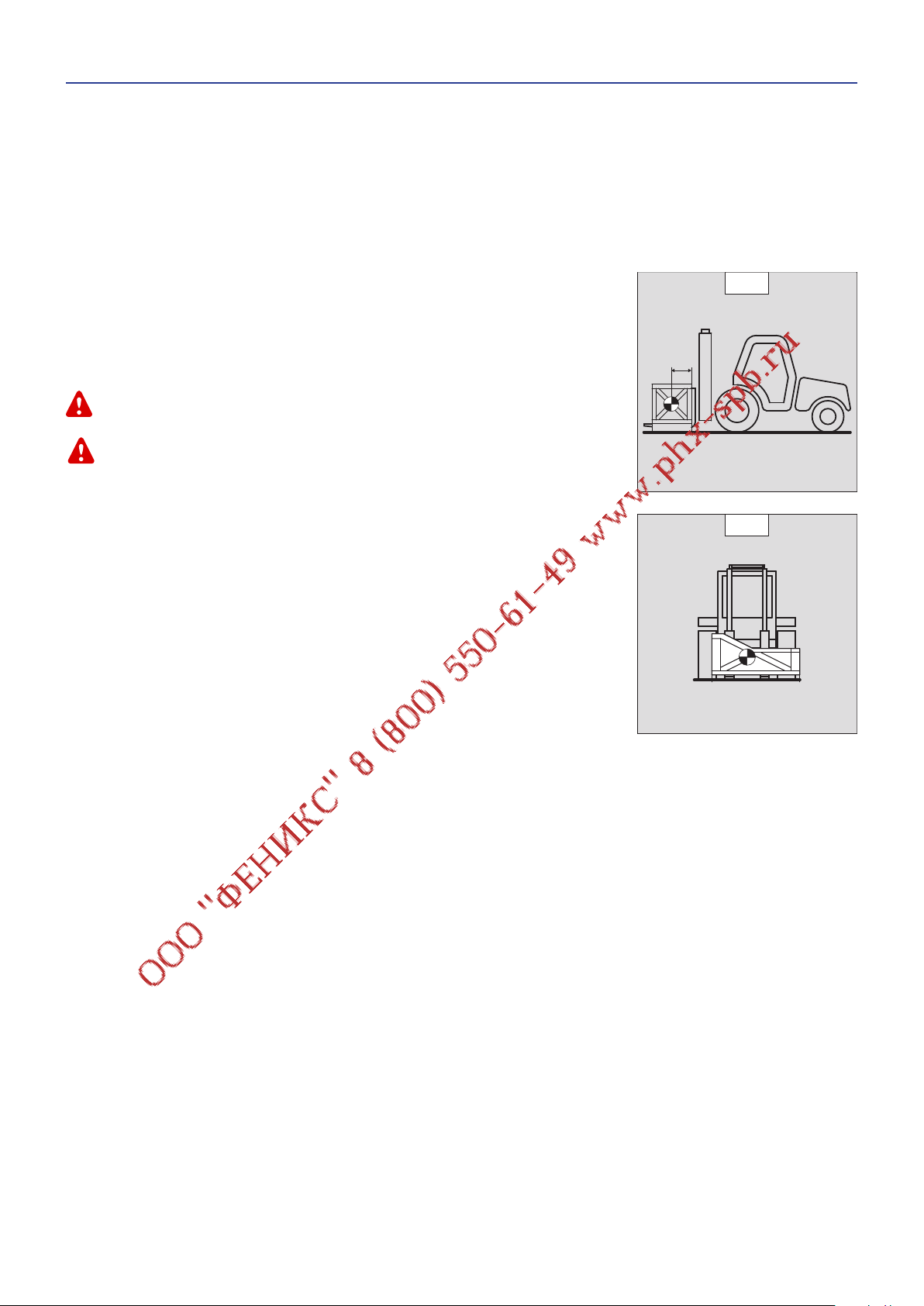
- The load chart for your lift truck is valid for a load in which the longitudinal position of the
centre of gravity is 500 or 600 mm from the base of the forks (as model of lift truck) (fig. B1). For
a higher centre of gravity, contact your dealer.
- For irregular loads, determine the transverse centre of gravity before any movement (fig. B2)
and set it in the longitudinal axis of the lift truck.
It is forbidden to move a load heavier than the effective capacity defined on the lift truck load chart.
For loads with a moving centre of gravity (e.g. liquids), take account of the variations in the centre of gravity
in order to determine the load to be handled and be vigilant and take extra care to limit these variations as
far as possible.
B1
500 mm
B2
1-13
Page 16
C - TRANSVERSE ATTITUDE OF THE LIFT TRUCK
647377 (31/03/2014)
The transverse attitude is the transverse slope of the chassis with respect to the horizontal.
Raising the load reduces the lift truck’s lateral stability. The transverse attitude must be set with the mast in down position as follows:
- Position the lift truck so that the bubble in the level is between the two lines (see: 2 - DESCRIPTION: INSTRUMENTS AND CONTROLS).
D - TAKING UP A LOAD ON THE GROUND
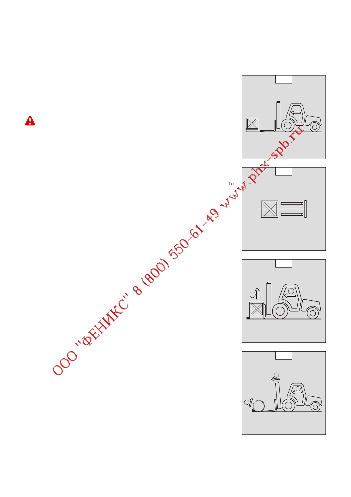
- Approach the lift truck perpendicular to the load, with the the forks in a horizontal position
(fig. D1).
- Adjust the fork spread and centering in connection with the load (fig. D2) (optional solutions
exist, consult your dealer).
- Never lift a load with a single fork.
Beware of the risks of trapping or squashing limbs when manually adjusting the forks.
- Move the lift truck forward slowly (1) and bring the forks to stop in front of the load (fig. D3), if
necessary, slightly lift the mast (2) while taking up the load.
- Bring the load into the transport position.
- Tilt the load far enough backwards to ensure stability (loss of load on braking or going downhill).
FOR A NON-PALLETIZED LOAD
- Tilt the carriage (1) forwards and move the lift truck slowly forwards (2), to insert the fork under
the load (fig. D4) (block the load if necessary).
- Continue to move the lift truck forwards (2) tilting the carriage (3) (fig. D4) backwards to
position the load on the forks and check the load’s longitudinal and lateral stability.
D1
D2
D3
2
1
D4
1
2
3
1-14
Page 17
E - TAKING UP AND LAYING A HIGH LOAD ON TYRES
647377 (31/03/2014)
You must not raise the mast if you have not checked the transverse attitude of the lift truck (see: INSTRUCTIONS
FOR HANDLING A LOAD: C - TRANSVERSE ATTITUDE OF THE LIFT TRUCK).
REMINDER: Make sure that the following operations can be performed with good visibility (see:
OPERATIONS INSTRUCTIONS UNLADEN AND LADEN: D - VISIBILITY).
E1
2
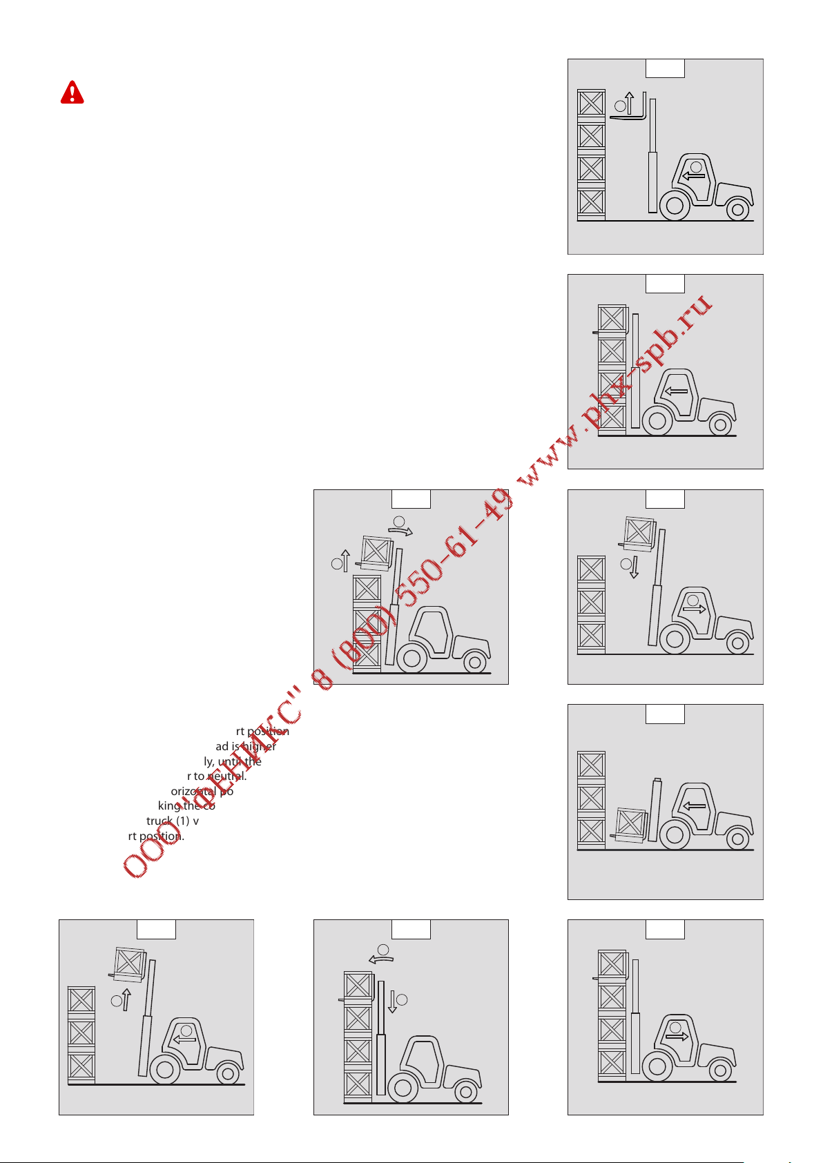
TAKING UP A HIGH LOAD ON TYRES
- Ensure that the forks will easily pass under the load.
- Keeping the mast vertical (1), advance the lift truck and raise the forks to level with the load
(2) (fig. E1).
- Manoeuvre carefully and gently to bring the forks to the stop in front of the load (fig. E2). Put
the handbrake on and set the forward/reverse selector to neutral.
- Slightly lift the load (1) and incline the carriage (2) backwards to stabilize the load (fig. E3).
- Tilt the load sufficiently backwards to ensure its stability.
- Reverse the lift truck (1) very carefully and gently to free the load. Lower the mast (2) to bring
the load into transport position (fig. E4).
E3
2
1
1
E2
E4
2
LAYING A HIGH LOAD ON TYRES
- Approach the load in the transport position in front of the pile (fig. E5).
- Raise the mast (1) until the load is higher than the pile and move the lift truck forward (2) (fig.
E6) very carefully and gently, until the load is over the pile. Put the handbrake on and set the
forward/reverse selector to neutral.
- Place the load in a horizontal position by tilting the mast forwards (1) and lay it down on the
pile (2) while checking the correct positioning of the load (fig. E7).
- Reverse the lift truck (1) very slowly and carefully to release the forks (fig. E8). Then set them
into transport position.
E6
1
E7
1
2
1
E5
E8
2
1
1-15
Page 18

MAINTENANCE INSTRUCTIONS OF THE LIFT TRUCK
647377 (31/03/2014)
GENERAL INSTRUCTIONS
- Ensure the area is sufficiently ventilated before starting the lift truck.
- Wear clothes suitable for the maintenance of the lift truck, avoid wearing jewellery and loose clothes. Tie and protect your hair, if necessary.
- Stop the I.C. engine and remove the ignition key, when an intervention is necessary.
- Read the operator’s manual carefully.
- Carry out all repairs immediately, even if the repairs concerned are minor.
- Repair all leaks immediately, even if the leak concerned is minor.
- Make sure that the disposal of process materials and of spare parts is carried out in total safety and in a ecological way.
- Be careful of the risk of burning and splashing (exhaust, radiator, I.C. engine, etc.).
MAINTENANCE
- Perform the periodic service (see: 3 - MAINTENANCE) to keep your lift truck in good working conditions. Failure to perform the periodic
service may cancel the contractual guarantee.
MAINTENANCE LOGBOOK
- The maintenance operations carried out in accordance with the recommendations given in part: 3 - MAINTENANCE and the other
inspection, servicing or repair operations or modifications performed on the lift truck or its attachments shall be recorded in a maintenance
logbook. The entry for each operation shall include details of the date of the works, the names of the individuals or companies having
performed them, the type of operation and its frequency, if applicable. The part numbers of any lift truck items replaced shall also be
indicated.
LUBRICANT AND FUEL LEVELS
- Use the recommended lubricants (never use contaminated lubricants).
- Do not fill the fuel tank when the I.C. engine is running.
- Only fill up the fuel tank in areas specified for this purpose.
- Do not fill the fuel tank to the maximum level.
- Do not smoke or approach the lift truck with a flame, when the fuel tank is open or is being filled.
HYDRAULIC
- Any work on the load handling hydraulic circuit is forbidden except for the operations described in part: 3 - MAINTENANCE.
- Do not attempt to loosen unions, hoses or any hydraulic component with the circuit under pressure.
BALANCING VALVE: It is dangerous to change the setting and remove the balancing valves or safety valves which may be fitted to your lift truck cylinders. These
operations must only be performed by approved personnel (consult your dealer).
The HYDRAULIC ACCUMULATORS that may be fitted on your lift truck are pressurised units. Removing these accumulators and their pipework is a dangerous
operation and must only be performed by approved personnel (consult your dealer).
ELECTRICITY
- Do not short-circuit the starter relay to start the IC engine. If the forward/reverse selector is not in neutral and the parking brake is not
engaged, the lift truck may suddenly start to move.
- Do not drop metallic items on the battery.
- Disconnect the battery before working on the electrical circuit.
1-16
Page 19

WELDING
647377 (31/03/2014)
- Disconnect the battery before any welding operations on the lift truck.
- When carrying out electric welding work on the lift truck, connect the negative cable from the equipment directly to the part being
welded, so as to avoid high tension current passing through the alternator.
- Never carry out welding or work which gives off heat on an assembled tyre. The heat would increase the pressure which could cause the
tyre to explode.
- If the lift truck is equipped with an electronic control unit, disconnect this before starting to weld, to avoid the risk of causing irreparable
damage to electronic components.
WASHING THE LIFT TRUCK
- Clean the lift truck or at least the area concerned before any intervention.
- Remember to close and lock all accesses to the lift truck (doors, windows, cowls…).
- During washing, avoid the articulations and electrical components and connections.
- If necessary, protect against penetration of water, steam or cleaning agents, components susceptible of being damaged, particularly
electrical components and connections and the injection pump.
- Clean the lift truck of any fuel, oil or grease trace.
FOR ANY INTERVENTION OTHER THAN REGULAR MAINTENANCE, CONSULT YOUR DEALER.
1-17
Page 20

IF THE LIFT TRUCK IS NOT TO BE USED FOR A LONG TIME
647377 (31/03/2014)
INTRODUCTION
The following recommendations are intended to prevent the lift truck from being damaged when it is withdrawn from service for an
extended period.
For these operations, we recommend the use of a MANITOU protective product, reference 603726.
Instructions for using the product are given on the packaging.
Procedures to follow if the lift truck is not to be used for a long time and for starting it up again afterwards must be performed by your dealership.
PREPARING THE LIFT TRUCK
- Clean the lift truck thoroughly.
- Check and repair any leakage of fuel, oil, water or air.
- Replace or repair any worn or damaged parts.
- Wash the painted surfaces of the lift truck in clear and cold water and wipe them.
- Touch up the paintwork if necessary.
- Shut down the lift truck (see: OPERATING INSTRUCTIONS UNLADEN AND LADEN).
- Make sure the mast cylinder rods are all in retracted position.
- Release the pressure in the hydraulic circuits.
PROTECTING THE I.C. ENGINE
- Fill the tank with fuel (see: 3 - MAINTENANCE: A - DAILY OR EVERY 10 HOURS SERVICE).
- Empty and replace the cooling liquid (see: 3 - MAINTENANCE: F - EVERY 2000 HOURS SERVICE).
- Leave the I.C. engine running at idling speed for a few minutes, then switch off.
- Replace the I.C. engine oil and oil filter (see: 3 - MAINTENANCE: D - EVERY 500 HOURS SERVICE).
- Add the protective product to the engine oil.
- Run the I.C. engine for a short time so that the oil and cooling liquid circulate inside.
- Disconnect the battery and store it in a safe place away from the cold, after charging it to a maximum.
- Remove the injectors and spray the protective product into each cylinder for two seconds with the piston in low neutral position.
- Turn the crankshaft once slowly and refit the injectors (see I.C. engine REPAIR MANUAL).
- Remove the intake hose from the manifold or turbocharger and spray the protective product into the manifold or turbocharger.
- Cap the intake manifold or turbocharger hole with waterproof adhesive tape.
- Remove the exhaust pipe and spray the protective product into the exhaust manifold or turbocharger.
- Refit the exhaust pipe and block the outlet with waterproof adhesive tape.
NOTE: The spray time is noted on the product packaging and must be increased by 50 % for turbo engines.
- Open the filler plug, spray the protective product around the rocker arm shaft and refit the filler plug.
- Cap the fuel tank using waterproof adhesive tape.
- Remove the drive belts and store them in a safe place.
- Disconnect the engine cut-off solenoid on the injection pump and carefully insulate the connection.
PROTECTING THE LIFT TRUCK
- Set the lift truck on axle stands so that the tyres are not in contact with the ground and release the handbrake.
- Protect cylinder rods which will not be retracted, from corrosion.
- Wrap the tyres.
NOTE: If the lift truck is to be stored outdoors, cover it with a waterproof tarpaulin.
1-18
Page 21

BRINGING THE LIFT TRUCK BACK INTO SERVICE
647377 (31/03/2014)
- Remove the waterproof adhesive tape from all the holes.
- Refit the intake hose.
- Refit and reconnect the battery.
- Remove the protection from the cylinder rods.
- Perform the daily service (see: 3 - MAINTENANCE: A - DAILY OR EVERY 10 HOURS SERVICE).
- Put the handbrake on and remove the axle stands.
- Empty and replace the fuel and replace the fuel filter (see: 3 - MAINTENANCE: D - EVERY 500 HOURS SERVICE).
- Refit and set the tension in the drive belts (see: 3 - MAINTENANCE: C - EVERY 250 HOURS SERVICE).
- Turn the I.C. engine using the starter, to allow the oil pressure to rise.
- Reconnect the engine cut-off solenoid.
- Lubricate the lift truck completely (see: 3 - MAINTENANCE: SERVICING SCHEDULE).
Make sure the area is adequately ventilated before starting up the lift truck.
- Start up the lift truck, following the safety instructions and regulations (see: OPERATING INSTRUCTIONS UNLADEN AND LADEN).
- Run all the mast’s hydraulic movements, concentrating on the ends of travel for each cylinder.
1-19
Page 22

647377 (31/03/2014)
1-20
Page 23

2 - DESCRIPTION
647377 (31/03/2014)
2-1
Page 24

647377 (31/03/2014)
2-2
Page 25

TABLE OF CONTENTS
647377 (31/03/2014)
« EC» DECLARATION OF CONFORMITY
IDENTIFICATION OF THE LIFT TRUCK
CHARACTERISTICS MI 15 D MI 18 D
CHARACTERISTICS MI 15 G MI 18 G
CHARACTERISTICS MI 20 D MI 25 D
CHARACTERISTICS MI 20 G MI 25 G
CHARACTERISTICS MI 30 D MI 35 D
CHARACTERISTICS MI 30 G MI 35 G
2-4
2-6
2-8
2-10
2-12
2-14
2-16
2-18
CHARACTERISTICS OF MASTS WITH ROLLERS AND LOAD CHARTS MI 15 D MI 15 G MI 18 D MI 18 G
CHARACTERISTICS OF MASTS WITH ROLLERS AND LOAD CHARTS MI 20 D MI 20 G MI 25 D MI 25 G
2-20
2-22
CHARACTERISTICS OF MASTS WITH ROLLERS AND LOAD CHARTS MI 30 D MI 30 G MI 35 D MI 35 G
FRONT AND REAR TIRES
INSTRUMENTS AND CONTROLS
TOWING PIN AND HOOK
2-26
2-28
2-38
2-24
2-3
Page 26

« EC» DECLARATION OF CONFORMITY
647377 (31/03/2014)
1)
DÉCLARATION «CE» DE CONFORMITÉ (originale)
«EC» DECLARATION OF CONFORMITY (original)
2) La société, The company : MANITOU BF
3) Adresse, Address : 430, rue de l’Aubinière - B.P. 10 249 - 44 158 - ANCENIS CEDEX - FRANCE
4) Dossier technique, Technical file : MANITOU BF - 430, rue de l’Aubinière
BP 10249 - 44158 - ANCENIS CEDEX - FRANCE
5) Constructeur de la machine décrite ci-après, Manufacturer of the machine described below :
MI 15 D / MI 15 G
MI 18 D / MI 18 G
MI 20 D / MI 20 G
MI 25 D / MI 25 G
MI 30 D / MI 30 G
MI 35 D / MI 35 G
6) Déclare que cette machine, Declares that this machine :
7) Est conforme aux directives suivantes et à leurs transpositions en droit national, Complies
with the following directives and their transpositions into national law :
2006/42/CE
8) Pour les machines annexe IV , For annex IV machines :
9) Numéro d’attestation, Certificate number :
10) Organisme notifié, Notified body :
15) Normes harmonisées utilisées, Harmonised standards used :
16) Normes ou dispositions techniques utilisées,
17) Fait à, Done at : Ancenis 18) Date, Date : 31/03/2014
19) Nom du signataire, Name of signatory : Fabrice BESLIN
20) Fonction, Function : Président division IMH
21) Signature, Signature :
Standards or technical provisions used
:
2-4
Page 27

bg : 1) удостоверение за « СЕ » съответствие (oригинална), 2) Фирмата, 3) Адрес, 4) Техническо досие, 5) Фабрикант на описаната по-долу машина, 6) Обявява, че тази машина, 7)
647377 (31/03/2014)
Отговаря на следните директиви и на тяхното съответствие национално право, 8) За машините към допълнение IV, 9)Номер на удостоверението, 10) Наименувана фирма, 15)
хармонизирани стандарти използвани, 16) стандарти или технически правила, използвани, 17) Изработено в, 18) Дата, 19) Име на разписалия се, 20) Функция, 21) Функция.
cs : 1) ES prohlášení o shodě (původní), 2) Název společnosti, 3) Adresa, 4) Technická dokumentace, 5) Výrobce níže uvedeného stroje, 6) Prohlašuje, že tento stroj,
7) Je v souladu s následujícími směrnicemi a směrnicemi transponovanými do vnitrostátního práva, 8) Pro stroje v příloze IV, 9) Číslo certifikátu, 10) Notifikační orgán,
15) harmonizované normy použity, 16) Norem a technických pravidel používaných, 17) Místo vydání, 18) Datum vydání, 19) Jméno podepsaného, 20) Funkce, 21) Podpis.
da : 1) EF Overensstemmelseserklæring (original), 2) Firmaet, 3) Adresse, 4) tekniske dossier, 5) Konstruktør af nedenfor beskrevne maskine, 6) Erklærer, at denne maskine,
7) Overholder nedennævnte direktiver og disses gennemførelse til national ret, 8) For maskiner under bilag IV, 9) Certifikat nummer, 10) Bemyndigede organ, 15) harmoniserede standarder,
der anvendes
de : 1) EG-Konformitätserklärung (original), 2) Die Firma, 3) Adresse, 4) Technischen Unterlagen, 5) Hersteller der nachfolgend beschriebenen Maschine, 6) Erklärt, dass diese
Maschine, 7) den folgenden Richtlinien und deren Umsetzung in die nationale Gesetzgebung entspricht, 8) Für die Maschinen laut Anhang IV, 9) Bescheinigungsnummer,
10) Benannte Stelle, 15) angewandten harmonisierten Normen, 16) angewandten sonstigen technischen Normen und Spezifikationen, 17) Ausgestellt in, 18) Datum,
19) Name des Unterzeichners, 20) Funktion, 21) Unterschrift.
el : 1) Δήλωση συμμόρφωσης CE (πρωτότυπο), 2) Η εταιρεία, 3) Διεύθυνση, 4) τεχνικό φάκελο, 5) Κατασκευάστρια του εξής περιγραφόμενου μηχανήματος,
6) Δηλώνει ότι αυτό το μηχάνημα, 7) Είναι σύμφωνο με τις εξής οδηγίες και τις προσαρμογές τους στο εθνικό δίκαιο, 8) Για τα μηχανήματα παραρτήματος IV,
9) Αριθμός δήλωσης, 10) Κοινοποιημένος φορέας, 15) εναρμονισμένα πρότυπα που χρησιμοποιούνται, 16) Πρότυπα ή τεχνικούς κανόνες που χρησιμοποιούνται,
16) Είναι σύμφωνο με τα εξής πρότυπα και τεχνικές διατάξεις, 17) Εν, 18) Ημερομηνία, 19) Όνομα του υπογράφοντος, 20) Θέση, 21) Υπογραφή.
es : 1)Declaración DE de conformidad (original), 2) La sociedad, 3) Dirección, 4) expediente técnico, 5) Constructor de la máquina descrita a continuación, 6) Declara que esta máquina, 7) Está
conforme a las siguientes directivas y a sus transposiciones en derecho nacional, 8) Para las máquinas anexo IV, 9) Número de certificación, 10) Organismo notificado, 15) normas armonizadas
utilizadas, 16) Otras normas o especificaciones técnicas utilizadas, 17) Hecho en, 18) Fecha, 19) Nombre del signatario, 20) Función, 21) Firma.
et : 1) EÜ vastavusdeklaratsioon (algupärane), 2) Äriühing, 3) Aadress, 4) Tehniline dokumentatsioon, 5) Seadme tootja, 6) Kinnitab, et see toode, 7) On vastavuses järgmiste
direktiivide ja nende riigisisesesse õigusesse ülevõtmiseks vastuvõetud õigusaktidega, 8) IV lisas loetletud seadmete puhul, 9) Tunnistuse number, 10) Sertifitseerimisasutus,
15) kasutatud ühtlustatud standarditele, 16) Muud standardites või spetsifikatsioonides kasutatakse, 17) Väljaandmise koht, 18) Väljaandmise aeg, 19) Allkirjastaja nimi,
20) Amet, 21) Allkiri.
fi : 1) EY-vaatimustenmukaisuusvakuutus (alkuperäiset), 2) Yritys, 3) Osoite, 4) teknisen eritelmän, 5) Jäljessä kuvatun koneen valmistaja, 6) Vakuuttaa, että tämä kone,
7) Täyttää seuraavien direktiivien sekä niitä vastaavien kansallisten säännösten vaatimukset, 8) Liitteen IV koneiden osalta, 9) Todistuksen numero, 10) Ilmoitettu laitos,
15) yhdenmukaistettuja standardeja käytetään, 16) muita standardeja tai eritelmät, 17) Paikka, 18) Aika, 19) Allekirjoittajan nimi, 20) Toimi, 21) Allekirjoitus.
ga : 1) « EC »dearbhú comhréireachta (bunaidh), 2) An comhlacht, 3) Seoladh, 4) comhad teicniúil, 5) Déantóir an innill a thuairiscítear thíos, 6) Dearbhaíonn sé go bhfuil an t-
inneall, 7) Go gcloíonn sé le na treoracha seo a leanas agus a trasuímh isteach i ndlí náisiúnta, 8) Le haghaidh innill an aguisín IV, 9) Uimhir teastais, 10) Comhlacht a chuireadh i bhfios,
15) caighdeáin comhchuibhithe a úsáidtear, 16) caighdeáin eile nó sonraíochtaí teicniúla a úsáidtear, 17) Déanta ag, 18) Dáta, 19) Ainm an tsínitheora, 20) Feidhm, 21) Síniú.
hu : 1) CE megfelelőségi nyilatkozat (eredeti), 2) A vállalat, 3) Cím, 4) műszaki dokumentáció, 5) Az alábbi gép gyártója, 6) Kijelenti, hogy a gép, 7) Megfelel az alábbi
irányelveknek valamint azok honosított előírásainak, 8) A IV. melléklet gépeihez, 9) Bizonylati szám, 10) Értesített szervezet, 15) felhasznált harmonizált szabványok,
16) egyéb felhasznált műszaki szabványok és előírások hivatkozásai, 17) Kelt (hely), 18) Dátum, 19) Aláíró neve, 20) Funkció, 21) Aláírás.
is : 1) (Samræmisvottorð ESB (upprunalega), 2) Fyrirtækið, 3) Aðsetur, 4) Tæknilegar skrá, 5) Smiður tækisins sem lýst er hér á eftir, 6) Staðfestir að tækið, 7) Samræmist
eftirfarandi stöðlum og staðfærslu þeirra með hliðsjón af þjóðarrétti, 8) Fyrir tækin í aukakafla IV, 9) Staðfestingarnúmer, 10) Tilkynnt til, 15) samhæfða staðla sem notaðir,
16) önnur staðlar eða forskriftir notað, 17) Staður, 18) Dagsetning, 19) Nafn undirritaðs, 20) Staða, 21) Undirskrift.
it : 1) Dichiarazione CE di conformità (originale), 2) La società, 3) Indirizzo, 4) fascicolo tecnico, 5) Costruttore della macchina descritta di seguito, 6) Dichiara che questa macchina, 7) È
conforme alle direttive seguenti e alle relative trasposizioni nel diritto nazionale, 8) Per le macchine Allegato IV, 9) Numero di Attestazione, 10) Organismo notificato, 15) norme armonizzate
applicate, 16) altre norme e specifiche tecniche applicate, 17) Stabilita a, 18) Data, 19) Nome del firmatario, 20) Funzione, 21) Firma.
lt : 1) CE atitikties deklaracija (originalas), 2) Bendrovė, 3) Adresas, 4) Techninė byla, 5) Žemiau nurodytas įrenginio gamintojas, 6) Pareiškia, kad šis įrenginys, 7) Atitinka toliau nurodytas
direktyvas ir į nacionalinius teisės aktus perkeltas jų nuostatas, 8) IV priedas dėl mašinų, 9) Sertifikato Nr, 10) Paskelbtoji įstaiga, 15) suderintus standartus naudojamus, 16) Kiti standartai ir
technines specifikacijas, 17) Pasirašyta, 18) Data, 19) Pasirašiusio asmens vardas ir pavardė, 20) Pareigos, 21) Parašas.
lv : 1) EK atbilstības deklarācija (oriģināls), 2) Uzņēmums, 3) Adrese, 4) tehniskās lietas, 5) Tālāk aprakstītās iekārtas ražotājs, 6) Apliecina, ka šī iekārta, 7) Ir atbilstoša tālāk norādītajām
direktīvām un to transpozīcijai nacionālajā likumdošanā, 8) Iekārtām IV pielikumā, 9) Apliecības numurs, 10) Reģistrētā organizācija, 15) lietotajiem saskaņotajiem standartiem, 16) lietotajiem
tehniskajiem standartiem un specifikācijām, 17) Sastādīts, 18) Datums, 19) Parakstītāja vārds, 20) Amats, 21) Paraksts.
mt : 1) Dikjarazzjoni ta’ Konformità KE (oriġinali), 2) Il-kumpanija, 3) Indirizz, 4) fajl tekniku, 5) Manifattriċi tal-magna deskritta hawn isfel, 6) Tiddikjara li din il-magna,
7) Hija konformi hija konformi mad-Direttivi segwenti u l-liġijiet li jimplimentawhom fil-liġi nazzjonali, 8) Għall-magni fl-Anness IV, 9) Numru taċ-ċertifikat, 10) Entità nnotifikata,
15) l-istandards armonizzati użati, 16) standards tekniċi u speċifikazzjonijiet oħra użati, 17) Magħmul f’, 18) Data, 19) Isem il-firmatarju, 20) Kariga, 21) Firma.
nl : 1) EG-verklaring van overeenstemming (oorspronkelijke), 2) Het bedrijf, 3) Adres, 4) technisch dossier, 5) Constructeur van de hierna genoemde machine, 6) Verklaart dat
deze machine, 7) In overeenstemming is met de volgende richtlijnen en hun omzettingen in het nationale recht, 8) Voor machines van bijlage IV, 9) Goedkeuringsnummer,
10) Aangezegde instelling, 15) gehanteerde geharmoniseerde normen, 16) andere gehanteerde technische normen en specificaties, 17) Opgemaakt te, 18) Datum,
19) Naam van ondergetekende, 20) Functie, 21) Handtekening.
no : 1) CE-samsvarserklæring (original), 2) Selskapet, 3) Adresse, 4) tekniske arkiv, 5) Fabrikant av følgende maskin, 6) Erklærer at denne maskinen, 7) Oppfyller kravene i følgende direktiver,
med nasjonale gjennomføringsbestemmelser, 8) For maskinene i tillegg IV, 9) Attestnummer, 10) Notifisert organ, 15) harmoniserte standarder som brukes, 16) Andre standarder og
spesifikasjoner brukt, 17) Utstedt i, 18) Dato, 19) Underskriverens navn, 20) Stilling, 21) Underskrift.
pl : 1) Deklaracja zgodności CE (oryginalne), 2) Spółka, 3) Adres, 4) dokumentacji technicznej, 5) Wykonawca maszyny opisanej poniżej, 6) Oświadcza, że ta maszyna,
7) Jest zgodna z następującymi dyrektywami i odpowiadającymi przepisami prawa krajowego, 8) Dla maszyn załącznik IV, 9) Numer certyfikatu, 10) Jednostka certyfikująca,
15) zastosowanych norm zharmonizowanych, 16) innych zastosowanych norm technicznych i specyfikacji, 17) Sporządzono w, 18) Data, 19) Nazwisko podpisującego,
20) Stanowisko, 21) Podpis.
pt : 1) Declaração de conformidade CE (original), 2) A empresa, 3) Morada, 4) processo técnico, 5) Fabricante da máquina descrita abaixo, 6) Declara que esta máquina,
7) Está em conformidade às directivas seguintes e às suas transposições para o direito nacional, 8) Para as máquinas no anexo IV, 9) Número de certificado,
10) Entidade notificada, 15) normas harmonizadas utilizadas, 16) outras normas e especificações técnicas utilizadas, 17) Elaborado em, 18) Data, 19) Nome do signatário,
20) Cargo, 21) Assinatura.
ro : 1) Declaraţie de conformitate CE (originală), 2) Societatea, 3) Adresa, 4) cărtii tehnice, 5) Constructor al maşinii descrise mai jos, 6) Declară că prezenta maşină,
7) Este conformă cu directivele următoare şi cu transpunerea lor în dreptul naţional, 8) Pentru maşinile din anexa IV, 9) Număr de atestare, 10) Organism notificat, 15) standardele armonizate
utilizate, 16) alte standarde si specificatii tehnice utilizate, 17) Întocmit la, 18) Data, 19) Numele persoanei care semnează, 20) Funcţia, 21) Semnătura.
sk : 1) ES vyhlásenie o zhode (pôvodný), 2) Názov spoločnosti, 3) Adresa, 4) technickej dokumentácie, 5) Výrobca nižšie opísaného stroja, 6) Vyhlasuje, že tento stroj,
7) Je v súlade s nasledujúcimi smernicami a smernicami transponovanými do vnútroštátneho práva, 8) Pre stroje v prílohe IV, 9) Číslo certifikátu, 10) Notifikačný orgán,
15) použité harmonizované normy, 16) použité iné technické normy a predpisy, 17) Miesto vydania, 18) Dátum vydania, 19) Meno podpisujúceho, 20) Funkcia, 21) Podpis.
sl : 1) ES Izjava o ustreznosti (izvirna), 2) Družba. 3) Naslov. 4) tehnične dokumentacije, 5) Proizvajalac tukaj opisanega stroja, 6) Izjavlja, da je ta stroj, 7) Ustreza
naslednjim direktivam in njihovi transpoziciji v državno pravo, 8) Za stroje priloga IV, 9) Številka potrdila, 10) Obvestilo organu, 15) uporabljene harmonizirane standarde,
16) druge uporabljene tehnične standarde in zahteve, 17) V, 18) Datum, 19) Ime podpisnika, 20) Funkcija, 21) Podpis.
sv : 1) CE-försäkran om överensstämmelse (original), 2) Företaget, 3) Adress, 4) tekniska dokumentationen, 5) Konstruktör av nedan beskrivna maskin, 6) Försäkrar att denna maskin, 7)
Överensstämmer med nedanstående direktiv och införlivandet av dem i nationell rätt, 8) För maskinerna i bilaga IV, 9) Nummer för godkännande, 10) Organism som underrättats, 15)
Harmoniserade standarder som använts, 16) andra tekniska standarder och specifikationer som använts, 17) Upprättat i, 18) Datum, 19) Namn på den som undertecknat, 20) Befattning, 21)
Namntecknin.
, 16) standarder eller tekniske regler, 17) Udfærdiget i, 18) Dato, 19) Underskrivers navn, 20) Funktion, 21) Underskrift.
2-5
Page 28
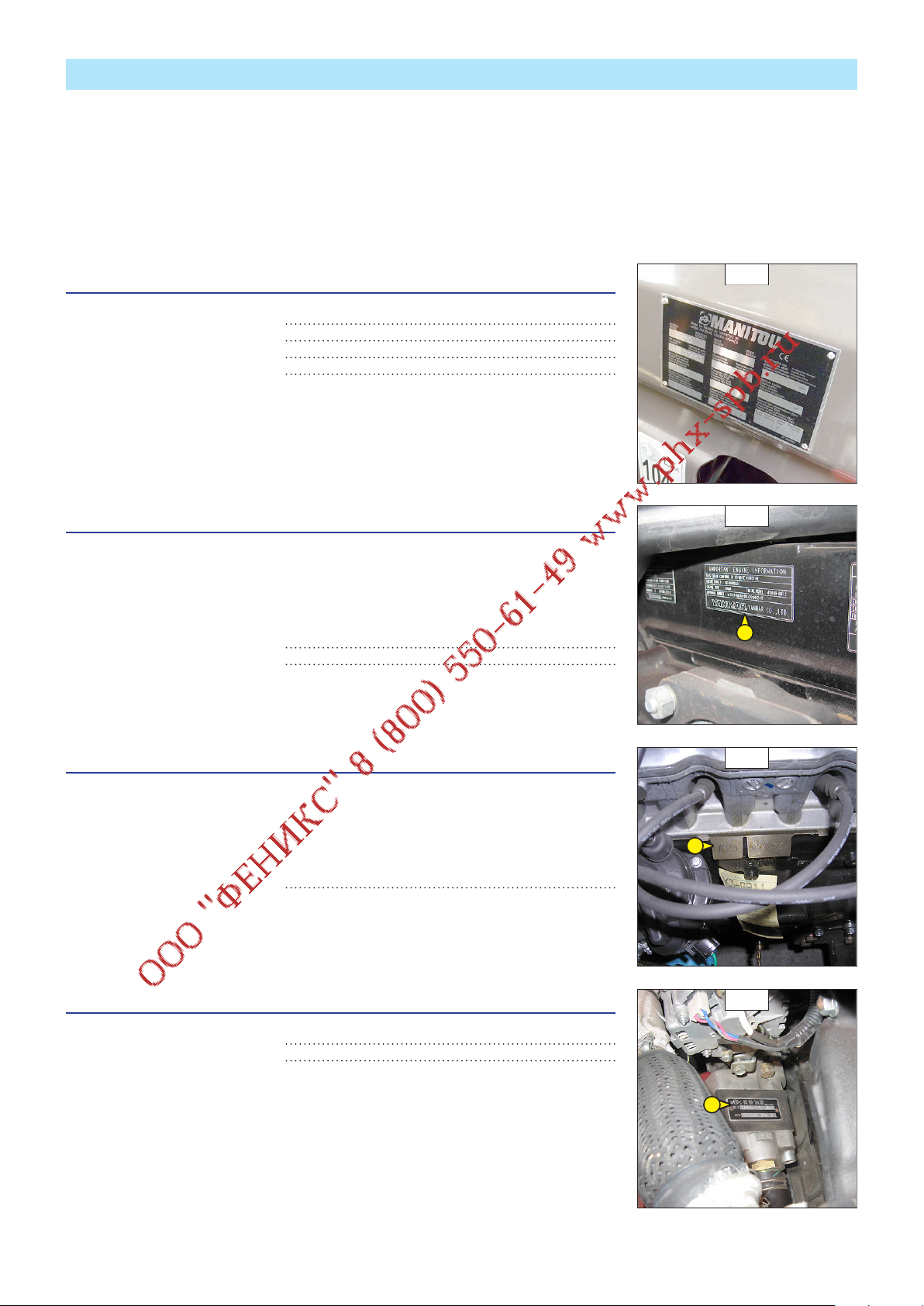
IDENTIFICATION OF THE LIFT TRUCK
647377 (31/03/2014)
As our policy is to promote a constant improvement of our products, our range of telescopic lift trucks may undergo certain modifications,
without obligation for us to advise our customers.
When you order parts, or when you require any technical information, always specify:
NOTE: For the owner's convenience, it is recommended that a note of these numbers is made in the spaces provided, at the time of the
delivery of the lift truck.
LIFT TRUCK MANUFACTURER'S PLATE (FIG. A)
- Model
- Series
- Serial Nr
- Year of manufacture
For any further technical information regarding your lift truck refer to chapter: 2 - DESCRIPTION:
CHARACTERISTICS.
ENGINE (FIG. B)
MI 15 D
MI 18 D
MI 20 D
MI 25 D
MI 30 D
MI 35 D
- Model
- Engine Nr
A
B
ENGINE (FIG. B)
MI 15 G
MI 18 G
MI 20 G
MI 25 G
MI 30 G
MI 35 G
- Engine Nr
HYDRAULIC POMP (FIG. C)
- Type
- Serial Nr
B
C
2-6
Page 29
CHASSIS (FIG. D)
647377 (31/03/2014)
- Type
- Serial Nr
D
MAST (FIG. E)
- Mast identification Nr
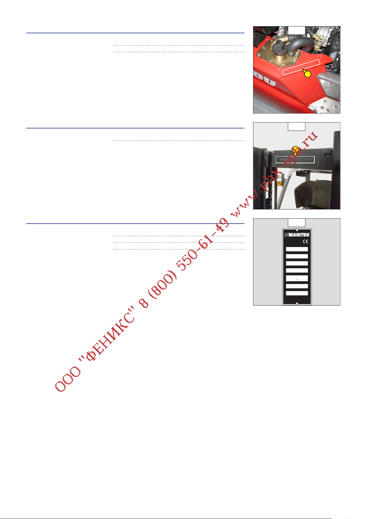
PLATE MANUFACTURER OF THE ATTACHMENT (FIG. F)
- Model
- Serial no.
- Year of manufacture
E
F
MANITOU BF
44158 ANCENIS CEDEX
FRANCE
MODELE
N° dans la série
Année fabrication
Masse à vide
C d G / Tablier
A vide / En charge : mm
Cap. Nominale
Pression de service
AVERTISSEMENT : RESPECTEZ
LA CAPACITE DE L'ENSEMBLE
"CHARIOT ET EQUIPEMENT"
kg
N°241415
2-7
Page 30

CHARACTERISTICS
647377 (31/03/2014)
MI 15 D
MI 18 D
NOTE: The specifications given are not binding on the manufacturer and can be modified without prior notification.
1.1
Manufacturer MANITOU MANITOU
1.2
Model type MI 15 D MI 18 D
1.3
Propulsion: battery, diesel, petrol, LPG, mains Diesel Diesel
1.4
Type of operation: manual, pedestrian, standing, seated Seated Seated
1.5
Rated capacity/load on forks (basic capacity)
DESIGNATION
1.6
Centre of gravity of the load
1.8
Distance from the load bearing surface to the centre of the front axle
1.9
Wheelbase
2.1
Kerb weight of truck
2.2
Front axle load laden
2.2.1
WEIGHT
RUNNING CARRIAGE
DIMENSIONS
Rear axle load laden
2.3
Front axle load unladen
2.3.1
Rear axle load unladen
3.1
Tyre equipment: bandage (V), super-elastic (SE), pneumatic (L) SE SE
3.2
Size of front wheels
3.3
Size of rear wheels
3.5
Number of front wheels (x = drive wheel) 2x 2x
3.5.1
Number of rear wheels (x = drive wheel) 2 2
3.6
Front wheel gauge (middle of wheels)
3.7
Rear wheel gauge (middle of wheels)
4.1
Tilt of mast forward
4.1.1
Tilt of mast backward
4.2
Height of mast lowered
4.3
Normal free lift
4.4
Lift height
4.5
Height mast extended
4.7
Height of driver protection (cab)
4.8
Height of seat
4.12
Height of towing coupling
4.19
Total length
4.20
Length of forks at heel
4.21
Total width, wheels Single / dual wheels (overall)
4.22
Section of fork arms
4.22.1
Width of fork arms
4.22.2
Length of fork arms
4.23
Fork carriage to DIN 15 173 A/B FEM2A FEM2A
4.24
Width of fork carriage (with load back-rest)
4.31
Ground clearance of mast
4.32
Ground clearance at centre of wheel-base
4.33
Aisle width for palette 1000x1200 widthways
4.34
Aisle width for palette 800x1200 lengthways
4.35
Turning radius (raised/lowered position)
4.36
Inner turning radius
Q (t)
c (mm)
x (mm)
y (mm)
kg
kg
kg
kg
kg
“ or mm
“ or mm
b10
(mm)
b11
(mm)
α (°)
β (°)
h1 (mm)
h2 (mm)
h3 (mm)
h4 (mm)
h6 (mm)
h7 (mm)
h10
(mm)
l1 (mm)
l2 (mm)
b1 (mm)
s (mm)
e (mm)
l (mm)
b3 (mm)
m1 (mm)
m2 (mm)
Ast (mm)
Ast (mm)
Wa (mm)
b13 (mm)
1,5 1,8
500 500
405 405
1 420 1 420
2 905 3 100
3 820 4 260
585 640
1 325 1 315
1 580 1 785
6.50-10 10PR 6.50-10 10PR
5.00-8 8PR 5.00-8 8PR
900 900
920 920
12 12
2 145 2 145
155 155
3 300 3 300
4 255 4 255
2 090 2 090
1 160 1 160
315 315
3 310 3 350
2 240 2 280
1 080/1 500 1 080/1 500
35 35
100 100
1 070 1 070
1 000 1 000
115 115
150 150
3 590 3 615
3 790 3 815
1 985 2 010
55 55
6 6
2-8
Page 31

5.1
647377 (31/03/2014)
5.1.1
5.2
5.2.1
5.3
5.3.1
5.5
5.5.1
PERFORMANCE
5.7
5.7.1
5.9
5.9.1
5.10
7.1
7.2
7.3
ENGINE
7.4
7.5
8.2
8.3
8.4
8.5
MISCELLANEOUS
Speed of travel laden
Speed of travel unladen
Speed of rise laden
Speed of rise unladen
Speed of lowering laden
Speed of lowering unladen
Nominal towing power laden
Nominal towing power unladen
Slope laden
Slope unladen
Acceleration time laden
Acceleration time unladen
km/h
km/h
m/s
m/s
m/s
m/s
N
N
%
%
18,5 18,6
19 19,3
0,50 0,50
0,55 0,55
0,50 0,50
0,55 0,55
14 500 14 400
7 600 7 950
>20 >20
>20 >20
s
s
Service brake Hydraulic Hydraulic
Engine manufacturer/Type
Power delivery
Rated speed
Number of pistons / Capacity
Fuel consumption
(according to VDI cycle)
Working hydraulic pressure for attachments
Oil flow rate for attachments
Measured/guaranteed mean noise level at the ear of the operator (when travelling)
(according to standard EN 12053)
kW
Rpm
cm³
l/h
Bar
L/mn
db (A)
YANMAR
4TNE92-HRJ
32,8 32,8
2 450 2 450
4/2 659 4/2 659
160 160
56 56
88 88
YANMAR
4TNE92-HRJ
Towing hook / DIN type
Average weighted acceleration on driver’s body
(according to standard NF EN 13059)
m/s
2
0,83 0,83
2-9
Page 32

CHARACTERISTICS
647377 (31/03/2014)
MI 15 G
MI 18 G
NOTE: The specifications given are not binding on the manufacturer and can be modified without prior notification.
1.1
Manufacturer MANITOU MANITOU
1.2
Model type MI 15 G MI 18 G
1.3
Propulsion: battery, diesel, petrol, LPG, mains GPL GPL
1.4
Type of operation: manual, pedestrian, standing, seated Seated Seated
1.5
Rated capacity/load on forks (basic capacity)
DESIGNATION
1.6
Centre of gravity of the load
1.8
Distance from the load bearing surface to the centre of the front axle
1.9
Wheelbase
2.1
Kerb weight of truck
2.2
Front axle load laden
2.2.1
WEIGHT
RUNNING CARRIAGE
DIMENSIONS
Rear axle load laden
2.3
Front axle load unladen
2.3.1
Rear axle load unladen
3.1
Tyre equipment: bandage (V), super-elastic (SE), pneumatic (L) SE SE
3.2
Size of front wheels
3.3
Size of rear wheels
3.5
Number of front wheels (x = drive wheel) 2x 2x
3.5.1
Number of rear wheels (x = drive wheel) 2 2
3.6
Front wheel gauge (middle of wheels)
3.7
Rear wheel gauge (middle of wheels)
4.1
Tilt of mast forward
4.1.1
Tilt of mast backward
4.2
Height of mast lowered
4.3
Normal free lift
4.4
Lift height
4.5
Height mast extended
4.7
Height of driver protection (cab)
4.8
Height of seat
4.12
Height of towing coupling
4.19
Total length
4.20
Length of forks at heel
4.21
Total width, wheels Single / dual wheels (overall)
4.22
Section of fork arms
4.22.1
Width of fork arms
4.22.2
Length of fork arms
4.23
Fork carriage to DIN 15 173 A/B FEM2A FEM2A
4.24
Width of fork carriage (with load back-rest)
4.31
Ground clearance of mast
4.32
Ground clearance at centre of wheel-base
4.33
Aisle width for palette 1000x1200 widthways
4.34
Aisle width for palette 800x1200 lengthways
4.35
Turning radius (raised/lowered position)
4.36
Inner turning radius
Q (t)
c (mm)
x (mm)
y (mm)
kg
kg
kg
kg
kg
“ or mm
“ or mm
b10
(mm)
b11
(mm)
α (°)
β (°)
h1 (mm)
h2 (mm)
h3 (mm)
h4 (mm)
h6 (mm)
h7 (mm)
h10
(mm)
l1 (mm)
l2 (mm)
b1 (mm)
s (mm)
e (mm)
l (mm)
b3 (mm)
m1 (mm)
m2 (mm)
Ast (mm)
Ast (mm)
Wa (mm)
b13 (mm)
1,5 1,8
500 500
405 405
1 420 1 420
2 710 2 905
3 640 4 160
570 545
1 230 1 215
1 480 1 690
6.50-10 10PR 6.50-10 10PR
5.00-8 8PR 5.00-8 8PR
900 900
920 920
12 12
2 145 2 145
155 155
3 300 3 300
4 255 4 255
2 090 2 090
1 160 1 160
315 315
3 310 3 350
2 240 2 280
1 080/1 500 1 080/1 500
35 35
100 100
1 070 1 070
1 000 1 000
115 115
150 150
3 590 3 615
3 790 3 815
1 985 2 010
55 55
6 6
2-10
Page 33

5.1
647377 (31/03/2014)
5.1.1
5.2
5.2.1
5.3
5.3.1
5.5
5.5.1
PERFORMANCE
5.7
5.7.1
5.9
5.9.1
5.10
7.1
7.2
7.3
ENGINE
7.4
7.5
8.2
8.3
8.4
8.5
MISCELLANEOUS
Speed of travel laden
Speed of travel unladen
Speed of rise laden
Speed of rise unladen
Speed of lowering laden
Speed of lowering unladen
Nominal towing power laden
Nominal towing power unladen
Slope laden
Slope unladen
Acceleration time laden
Acceleration time unladen
km/h
km/h
m/s
m/s
m/s
m/s
N
N
%
%
17,5 17,5
18 18
0,45 0,45
0,55 0,55
0,50 0,50
0,55 0,55
14 600 14 500
7 700 8 000
>20 >20
>20 >20
s
s
Service brake Hydraulic Hydraulic
Engine manufacturer/Type NISSAN K21 NISSAN K21
Power delivery
Rated speed
Number of pistons / Capacity
Fuel consumption
Working hydraulic pressure for attachments
Oil flow rate for attachments
Measured/guaranteed mean noise level at the ear of the operator (when travelling)
(according to standard EN 12053)
Up to machine N°856887
From machine N°856888
Up to machine N°856887
From machine N°856888
(according to VDI cycle)
Up to machine N°856887
From machine N°856888
kW
Rpm
cm³
l/h
Bar
L/mn
db (A)
31,5
29
2 300
2250
4/2 065 4/2 065
160 160
53
52
86 86
31,5
29
2 300
2250
53
52
Towing hook / DIN type
Average weighted acceleration on driver’s body
(according to standard NF EN 13059)
m/s
2
0,83 0,83
2-11
Page 34

CHARACTERISTICS
647377 (31/03/2014)
MI 20 D
MI 25 D
NOTE: The specifications given are not binding on the manufacturer and can be modified without prior notification.
1.1
Manufacturer MANITOU MANITOU
1.2
Model type MI 20 D MI 25 D
1.3
Propulsion: battery, diesel, petrol, LPG, mains Diesel Diesel
1.4
Type of operation: manual, pedestrian, standing, seated Seated Seated
1.5
Rated capacity/load on forks (basic capacity)
DESIGNATION
1.6
Centre of gravity of the load
1.8
Distance from the load bearing surface to the centre of the front axle
1.9
Wheelbase
2.1
Kerb weight of truck
2.2
Front axle load laden
2.2.1
WEIGHT
RUNNING CARRIAGE
DIMENSIONS
Rear axle load laden
2.3
Front axle load unladen
2.3.1
Rear axle load unladen
3.1
Tyre equipment: bandage (V), super-elastic (SE), pneumatic (L) SE SE
3.2
Size of front wheels
3.3
Size of rear wheels
3.5
Number of front wheels (x = drive wheel) 2x 2x
3.5.1
Number of rear wheels (x = drive wheel) 2 2
3.6
Front wheel gauge (middle of wheels)
3.7
Rear wheel gauge (middle of wheels)
4.1
Tilt of mast forward
4.1.1
Tilt of mast backward
4.2
Height of mast lowered
4.3
Normal free lift
4.4
Lift height
4.5
Height mast extended
4.7
Height of driver protection (cab)
4.8
Height of seat
4.12
Height of towing coupling
4.19
Total length
4.20
Length of forks at heel
4.21
Total width, wheels Single / dual wheels (overall)
4.22
Section of fork arms
4.22.1
Width of fork arms
4.22.2
Length of fork arms
4.23
Fork carriage to DIN 15 173 A/B FEM2A FEM2A
4.24
Width of fork carriage (with load back-rest)
4.31
Ground clearance of mast
4.32
Ground clearance at centre of wheel-base
4.33
Aisle width for palette 1000x1200 widthways
4.34
Aisle width for palette 800x1200 lengthways
4.35
Turning radius (raised/lowered position)
4.36
Inner turning radius
Q (t)
c (mm)
x (mm)
y (mm)
kg
kg
kg
kg
kg
“ or mm
“ or mm
b10
(mm)
b11
(mm)
α (°)
β (°)
h1 (mm)
h2 (mm)
h3 (mm)
h4 (mm)
h6 (mm)
h7 (mm)
h10
(mm)
l1 (mm)
l2 (mm)
b1 (mm)
s (mm)
e (mm)
l (mm)
b3 (mm)
m1 (mm)
m2 (mm)
Ast (mm)
Ast (mm)
Wa (mm)
b13 (mm)
2,0 2,5
500 500
465 465
1 600 1 600
3 725 4 000
5 005 5 735
720 765
1 765 1 710
1 960 2 290
7.00-12 12PR 7.00-12 12PR
6.00-9 10PR 6.00-9 10PR
965 965
973 973
12 12
2 185 2 185
140 140
3 300 3 300
4 345 4 345
2 115 2 115
1190 1190
355 360
3 615 3 685
2 465 2 535
1 155/1 595 1 155/1 595
40 40
122 122
1 150 1 150
1 038 1 038
115 115
175 175
3 865 3 930
4 065 4 130
2 200 2 265
145 145
6 6
2-12
Page 35

5.1
647377 (31/03/2014)
5.1.1
5.2
5.2.1
5.3
5.3.1
5.5
5.5.1
PERFORMANCE
5.7
5.7.1
5.9
5.9.1
5.10
7.1
7.2
7.3
ENGINE
7.4
7.5
8.2
8.3
8.4
8.5
MISCELLANEOUS
Speed of travel laden
Speed of travel unladen
Speed of rise laden
Speed of rise unladen
Speed of lowering laden
Speed of lowering unladen
Nominal towing power laden
Nominal towing power unladen
Slope laden
Slope unladen
Acceleration time laden
Acceleration time unladen
km/h
km/h
m/s
m/s
m/s
m/s
N
N
%
%
18 18
18,5 18,6
0,56 0,56
0,58 0,58
0,48 0,50
0,55 0,55
19 000 19 400
10 200 10 250
>20 >20
>20 >20
s
s
Service brake Hydraulic Hydraulic
Engine manufacturer/Type
Power delivery
Rated speed
Number of pistons / Capacity
Fuel consumption
(according to VDI cycle)
Working hydraulic pressure for attachments
Oil flow rate for attachments
Measured/guaranteed mean noise level at the ear of the operator (when travelling)
(according to standard EN 12053)
kW
Rpm
cm³
l/h
Bar
L/mn
db (A)
YANMAR
4TNE98-BQFLC
42,1 42,1
2 300 2 300
4/3 319 4/3 319
3,94 3,94
160 160
69 69
89 89
YANMAR
4TNE98-BQFLC
Towing hook / DIN type
Average weighted acceleration on driver’s body
(according to standard NF EN 13059)
m/s
2
0,78 0,78
2-13
Page 36

CHARACTERISTICS
647377 (31/03/2014)
MI 20 G
MI 25 G
NOTE: The specifications given are not binding on the manufacturer and can be modified without prior notification.
1.1
Manufacturer MANITOU MANITOU
1.2
Model type MI 20 G MI 25 G
1.3
Propulsion: battery, diesel, petrol, LPG, mains GPL GPL
1.4
Type of operation: manual, pedestrian, standing, seated Seated Seated
1.5
Rated capacity/load on forks (basic capacity)
DESIGNATION
1.6
Centre of gravity of the load
1.8
Distance from the load bearing surface to the centre of the front axle
1.9
Wheelbase
2.1
Kerb weight of truck
2.2
Front axle load laden
2.2.1
WEIGHT
RUNNING CARRIAGE
DIMENSIONS
Rear axle load laden
2.3
Front axle load unladen
2.3.1
Rear axle load unladen
3.1
Tyre equipment: bandage (V), super-elastic (SE), pneumatic (L) SE SE
3.2
Size of front wheels
3.3
Size of rear wheels
3.5
Number of front wheels (x = drive wheel) 2x 2x
3.5.1
Number of rear wheels (x = drive wheel) 2 2
3.6
Front wheel gauge (middle of wheels)
3.7
Rear wheel gauge (middle of wheels)
4.1
Tilt of mast forward
4.1.1
Tilt of mast backward
4.2
Height of mast lowered
4.3
Normal free lift
4.4
Lift height
4.5
Height mast extended
4.7
Height of driver protection (cab)
4.8
Height of seat
4.12
Height of towing coupling
4.19
Total length
4.20
Length of forks at heel
4.21
Total width, wheels Single / dual wheels (overall)
4.22
Section of fork arms
4.22.1
Width of fork arms
4.22.2
Length of fork arms
4.23
Fork carriage to DIN 15 173 A/B FEM2A FEM2A
4.24
Width of fork carriage (with load back-rest)
4.31
Ground clearance of mast
4.32
Ground clearance at centre of wheel-base
4.33
Aisle width for palette 1000x1200 widthways
4.34
Aisle width for palette 800x1200 lengthways
4.35
Turning radius (raised/lowered position)
4.36
Inner turning radius
Q (t)
c (mm)
x (mm)
y (mm)
kg
kg
kg
kg
kg
“ or mm
“ or mm
b10
(mm)
b11
(mm)
α (°)
β (°)
h1 (mm)
h2 (mm)
h3 (mm)
h4 (mm)
h6 (mm)
h7 (mm)
h10
(mm)
l1 (mm)
l2 (mm)
b1 (mm)
s (mm)
e (mm)
l (mm)
b3 (mm)
m1 (mm)
m2 (mm)
Ast (mm)
Ast (mm)
Wa (mm)
b13 (mm)
2,0 2,5
500 500
465 465
1 600 1 600
3 620 3 895
4 930 5 665
690 730
1 720 1 665
1 900 2 230
7.00-12 12PR 7.00-12 12PR
6.00-9 10PR 6.00-9 10PR
965 965
973 973
12 12
2 185 2 185
140 140
3 300 3 300
4 345 4 345
2 115 2 115
1190 1190
355 360
3 615 3 685
2 465 2 535
1 155/1 595 1 155/1 595
40 40
122 122
1 150 1 150
1 038 1 038
115 115
175 175
3 865 3 930
4 065 4 130
2 200 2 265
145 145
6 6
2-14
Page 37

5.1
647377 (31/03/2014)
5.1.1
5.2
5.2.1
5.3
5.3.1
5.5
5.5.1
PERFORMANCE
5.7
5.7.1
5.9
5.9.1
5.10
7.1
7.2
7.3
ENGINE
7.4
7.5
8.2
8.3
8.4
8.5
MISCELLANEOUS
Speed of travel laden
Speed of travel unladen
Speed of rise laden
Speed of rise unladen
Speed of lowering laden
Speed of lowering unladen
Nominal towing power laden
Nominal towing power unladen
Slope laden
Slope unladen
Acceleration time laden
Acceleration time unladen
km/h
km/h
m/s
m/s
m/s
m/s
N
N
%
%
18,8 19,4
19,4 19,7
0,56 0,56
0,55 0,55
0,48 0,50
0,50 0,50
16 800 17 000
10 400 10 400
>20 >20
>20 >20
s
s
Service brake Hydraulic Hydraulic
Engine manufacturer/Type NISSAN K25 NISSAN K25
Power delivery
Rated speed
Number of pistons / Capacity
Fuel consumption
Working hydraulic pressure for attachments
Oil flow rate for attachments
Measured/guaranteed mean noise level at the ear of the operator (when travelling)
(according to standard EN 12053)
Up to machine N°856887
From machine N°856888
(according to VDI cycle)
kW
Rpm
cm³
l/h
Bar
L/mn
db (A)
38
35
38
35
2 400 2 400
4/2 488 4/2 488
6,3 6,3
160 160
72 72
86 86
Towing hook / DIN type
Average weighted acceleration on driver’s body
(according to standard NF EN 13059)
m/s
2
0,78 0,78
2-15
Page 38

CHARACTERISTICS
647377 (31/03/2014)
MI 30 D
MI 35 D
NOTE: The specifications given are not binding on the manufacturer and can be modified without prior notification.
1.1
Manufacturer MANITOU MANITOU
1.2
Model type MI 30 D MI 35 D
1.3
Propulsion: battery, diesel, petrol, LPG, mains Diesel Diesel
1.4
Type of operation: manual, pedestrian, standing, seated Seated Seated
1.5
Rated capacity/load on forks (basic capacity)
DESIGNATION
1.6
Centre of gravity of the load
1.8
Distance from the load bearing surface to the centre of the front axle
1.9
Wheelbase
2.1
Kerb weight of truck
2.2
Front axle load laden
2.2.1
WEIGHT
RUNNING CARRIAGE
DIMENSIONS
Rear axle load laden
2.3
Front axle load unladen
2.3.1
Rear axle load unladen
3.1
Tyre equipment: bandage (V), super-elastic (SE), pneumatic (L) SE SE
3.2
Size of front wheels
3.3
Size of rear wheels
3.5
Number of front wheels (x = drive wheel) 2x 2x
3.5.1
Number of rear wheels (x = drive wheel) 2 2
3.6
Front wheel gauge (middle of wheels)
3.7
Rear wheel gauge (middle of wheels)
4.1
Tilt of mast forward
4.1.1
Tilt of mast backward
4.2
Height of mast lowered
4.3
Normal free lift
4.4
Lift height
4.5
Height mast extended
4.7
Height of driver protection (cab)
4.8
Height of seat
4.12
Height of towing coupling
4.19
Total length
4.20
Length of forks at heel
4.21
Total width, wheels Single / dual wheels (overall)
4.22
Section of fork arms
4.22.1
Width of fork arms
4.22.2
Length of fork arms
4.23
Fork carriage to DIN 15 173 A/B FEM3A FEM3A
4.24
Width of fork carriage (with load back-rest)
4.31
Ground clearance of mast
4.32
Ground clearance at centre of wheel-base
4.33
Aisle width for palette 1000x1200 widthways
4.34
Aisle width for palette 800x1200 lengthways
4.35
Turning radius (raised/lowered position)
4.36
Inner turning radius
Q (t)
c (mm)
x (mm)
y (mm)
kg
kg
kg
kg
kg
“ or mm
“ or mm
b10
(mm)
b11
(mm)
α (°)
β (°)
h1 (mm)
h2 (mm)
h3 (mm)
h4 (mm)
h6 (mm)
h7 (mm)
h10
(mm)
l1 (mm)
l2 (mm)
b1 (mm)
s (mm)
e (mm)
l (mm)
b3 (mm)
m1 (mm)
m2 (mm)
Ast (mm)
Ast (mm)
Wa (mm)
b13 (mm)
3,0 3,5
500 500
480 485
1 700 1 700
4 610 4 860
6 650 7 360
960 1 000
1 860 1 825
2 750 3 035
28x9-15 12PR 28x9-15 12PR
6.50-10 10PR 6.50-10 10PR
1 005 1 005
975 975
12 12
2 200 2 315
145 145
3 300 3 300
4 445 4 445
2 130 2 130
1 215 1 215
355 360
3 865 3 935
2 715 2 785
1 225/1 725 1 225/1 725
45 50
122 122
1 150 1 150
1 100 1 100
130 130
200 200
4 140 4 195
4 340 4 395
2 460 2 510
160 160
6 6
2-16
Page 39

5.1
647377 (31/03/2014)
5.1.1
5.2
5.2.1
5.3
5.3.1
5.5
5.5.1
PERFORMANCE
5.7
5.7.1
5.9
5.9.1
5.10
7.1
7.2
7.3
ENGINE
7.4
7.5
8.2
8.3
8.4
8.5
MISCELLANEOUS
Speed of travel laden
Speed of travel unladen
Speed of rise laden
Speed of rise unladen
Speed of lowering laden
Speed of lowering unladen
Nominal towing power laden
Nominal towing power unladen
Slope laden
Slope unladen
Acceleration time laden
Acceleration time unladen
km/h
km/h
m/s
m/s
m/s
m/s
N
N
%
%
18 18
18,5 18,5
0,45 0,39
0,52 0,40
0,43 0,40
0,48 0,35
20 000 20 500
10 600 10 800
>20 >18
>20 >20
s
s
Service brake Hydraulic Hydraulic
Engine manufacturer/Type
Power delivery
Rated speed
Number of pistons / Capacity
Fuel consumption
(according to VDI cycle)
Working hydraulic pressure for attachments
Oil flow rate for attachments
Measured/guaranteed mean noise level at the ear of the operator (when travelling)
(according to standard EN 12053)
kW
Rpm
cm³
l/h
Bar
L/mn
db (A)
YANMAR
4TNE98-BQFLC
42,1 42,1
2 300 2 300
4/3 319 4/3 319
3,94 3,94
160 160
69 69
89 89
YANMAR
4TNE98-BQFLC
Towing hook / DIN type
Average weighted acceleration on driver’s body
(according to standard NF EN 13059)
m/s
2
0,5 0,5
2-17
Page 40

CHARACTERISTICS
647377 (31/03/2014)
MI 30 G
MI 35 G
NOTE: The specifications given are not binding on the manufacturer and can be modified without prior notification.
1.1
Manufacturer MANITOU MANITOU
1.2
Model type MI 30 G MI 35 G
1.3
Propulsion: battery, diesel, petrol, LPG, mains GPL GPL
1.4
Type of operation: manual, pedestrian, standing, seated Seated Seated
1.5
Rated capacity/load on forks (basic capacity)
DESIGNATION
1.6
Centre of gravity of the load
1.8
Distance from the load bearing surface to the centre of the front axle
1.9
Wheelbase
2.1
Kerb weight of truck
2.2
Front axle load laden
2.2.1
WEIGHT
RUNNING CARRIAGE
DIMENSIONS
Rear axle load laden
2.3
Front axle load unladen
2.3.1
Rear axle load unladen
3.1
Tyre equipment: bandage (V), super-elastic (SE), pneumatic (L) SE SE
3.2
Size of front wheels
3.3
Size of rear wheels
3.5
Number of front wheels (x = drive wheel) 2x 2x
3.5.1
Number of rear wheels (x = drive wheel) 2 2
3.6
Front wheel gauge (middle of wheels)
3.7
Rear wheel gauge (middle of wheels)
4.1
Tilt of mast forward
4.1.1
Tilt of mast backward
4.2
Height of mast lowered
4.3
Normal free lift
4.4
Lift height
4.5
Height mast extended
4.7
Height of driver protection (cab)
4.8
Height of seat
4.12
Height of towing coupling
4.19
Total length
4.20
Length of forks at heel
4.21
Total width, wheels Single / dual wheels (overall)
4.22
Section of fork arms
4.22.1
Width of fork arms
4.22.2
Length of fork arms
4.23
Fork carriage to DIN 15 173 A/B FEM3A FEM3A
4.24
Width of fork carriage (with load back-rest)
4.31
Ground clearance of mast
4.32
Ground clearance at centre of wheel-base
4.33
Aisle width for palette 1000x1200 widthways
4.34
Aisle width for palette 800x1200 lengthways
4.35
Turning radius (raised/lowered position)
4.36
Inner turning radius
Q (t)
c (mm)
x (mm)
y (mm)
kg
kg
kg
kg
kg
“ or mm
“ or mm
b10
(mm)
b11
(mm)
α (°)
β (°)
h1 (mm)
h2 (mm)
h3 (mm)
h4 (mm)
h6 (mm)
h7 (mm)
h10
(mm)
l1 (mm)
l2 (mm)
b1 (mm)
s (mm)
e (mm)
l (mm)
b3 (mm)
m1 (mm)
m2 (mm)
Ast (mm)
Ast (mm)
Wa (mm)
b13 (mm)
3,0 3,5
500 500
480 485
1 700 1 700
4 490 4 740
6 560 7 260
930 980
1 805 1 775
2 685 2 965
28x9-15 12PR 28x9-15 12PR
6.50-10 10PR 6.50-10 10PR
1 005 1 005
975 975
12 12
2 200 2 315
145 145
3 300 3 300
4 445 4 445
2 130 2 130
1 215 1 215
355 360
3 865 3 935
2 715 2 785
1 225/1 725 1 225/1 725
45 50
122 122
1 150 1 150
1 100 1 100
130 130
200 200
4 140 4 195
4 340 4 395
2 460 2 510
160 160
6 6
2-18
Page 41

5.1
647377 (31/03/2014)
5.1.1
5.2
5.2.1
5.3
5.3.1
5.5
5.5.1
PERFORMANCE
5.7
5.7.1
5.9
5.9.1
5.10
7.1
7.2
7.3
ENGINE
7.4
7.5
8.2
8.3
8.4
8.5
MISCELLANEOUS
Speed of travel laden
Speed of travel unladen
Speed of rise laden
Speed of rise unladen
Speed of lowering laden
Speed of lowering unladen
Nominal towing power laden
Nominal towing power unladen
Slope laden
Slope unladen
Acceleration time laden
Acceleration time unladen
km/h
km/h
m/s
m/s
m/s
m/s
N
N
%
%
18 17
18,5 17,5
0,45 0,40
0,55 0,52
0,48 0,47
0,50 0,38
17 400 17 500
10 800 11 000
>20 >18
>20 >20
s
s
Service brake Hydraulic Hydraulic
Engine manufacturer/Type NISSAN K25 NISSAN K25
Power delivery
Rated speed
Number of pistons / Capacity
Fuel consumption
Working hydraulic pressure for attachments
Oil flow rate for attachments
Measured/guaranteed mean noise level at the ear of the operator (when travelling)
(according to standard EN 12053)
Up to machine N°856887
From machine N°856888
(according to VDI cycle)
kW
Rpm
cm³
l/h
Bar
L/mn
db (A)
38
35
38
35
2 400 2 400
4/2 488 4/2 488
6,3 6,3
160 160
72 72
86 86
Towing hook / DIN type
Average weighted acceleration on driver’s body
(according to standard NF EN 13059)
m/s
2
0,5 0,5
2-19
Page 42

CHARACTERISTICS OF MASTS WITH ROLLERS AND LOAD CHARTS
647377 (31/03/2014)
MI 15 D MI 15 G
MI 18 D MI 18 G
NOTE: The specifications given are not binding on the manufacturer and can be modified without prior notification.
(kg)
capacity
Height at max.
Height at max.
capacity
Height at max.
CoG at 500mm
capacity
(kg)
CoG at 500mm
1400 1650
1650kg
to 3300
1400kg
to 3300
1500 1750
1400 1650
1650kg
to 3700
1400kg
to 3700
1500 1750
1400 1550
1550kg
to 4000
1400kg
to 4000
1500 1650
1400 1650
1650kg
to 3300
1400kg
to 3300
1500 1750
1400 1650
1650kg
to 3700
1400kg
to 3700
1500 1750
1400 1550
1550kg
to 4000
1400kg
to 4000
1500 1650
1200 1500
1650kg
to 4000
1350kg
to 4000
1300 1600
1050 1450
1600kg
to 4000
1300kg
to 4000
1150 1550
1050 1450
1550kg
to 4000
1250kg
to 4000
1150 1550
1000 1150
1450kg
to 4000
1250kg
to 4000
1100 1250
750 900
1400kg
to 4000
1200kg
to 4000
850 950
1400kg
1200kg
500 600
to 4000
to 4000
600 650
VALUES ON FORKS VALUES WITH TDL VALUES WITH PDF
Height at max.
capacity
Height at max.
Height at max.
capacity
(kg)
CoG at 500mm
capacity
h4
1,5 t 1,8 t 1,5 t 1,8 t 1,5 t 1,8 t 1,5 t 1,8 t 1,5 t 1,8 t 1,5 t 1,8 t
β
Rear
α
Front
without
extended
back-rest
1750kg
to 3300
1750kg
to 3700
1650kg
to 4000
1500 1700 4000
1700kg
to 4000
1750kg
to 3300
1750kg
to 3700
1650kg
to 4000
1500 1700 4000
1700kg
to 4000
1700kg
to 4000
1400kg
to 4000
1300 1700
1700kg
to 4000
1450kg
to 4000
1650kg
to 4000
1400kg
to 4000
1250 1650
1700kg
to 4000
1450kg
to 4000
1600kg
to 4000
1350kg
to 4000
1250 1650
1700kg
to 4000
1400kg
to 4000
1500kg
to 4000
1350kg
to 4000
1200 1350
1600kg
to 4000
1400kg
to 4000
1450kg
to 4000
1300kg
to 4000
950 1050
1500kg
to 4000
1350kg
to 4000
1450kg
to 4000
1300kg
to 4000
700 750
1500kg
to 4000
1350kg
to 4000
HEIGHT OF MAST TILT ANGLE
LIFT
FREE
MAST
LIFTING
MI 15 G
MI 15 D
h4
MI 18 G
MI 18 D
with
extended
h1
lowered
mm h2
back-rest
3300 std 155 2145 4255 3865 6° 12° 3300 3300 1500 1800 3300
DUPLEX
3700 155 2395 4655 4265 6° 12° 3700 3700 1500 1800 3700
TOTAL
3300 1575 2160 4245 3885 6° 12° 3300 3300 1500 1800 3300
3700 1775 2360 4646 4285 6° 12° 3700 3700 1500 1800 3700
4000 1975 2560 4945 4585 6° 12° 4000
4500 1500 2120 5455 5130 6° 6°
4700 1585 2170 5705 5380 6° 6°
4800 1600 2220 5755 5430 6° 6°
5000 1685 2270 5955 5595 6° 6°
TRIPLEX
FREE LIFT
5500 1885 2470 6455 6095 3° 6°
6000 2100 2720 7055 6730 3° 6°
6500 2200 2870 7455 7180 3° 6° - - - - - - - - - - - -
4000 155 2595 4955 4600 6° 12° 4000
DUPLEX
VISIBILITY
FREE LIFT
2-20
Page 43

RATED CAPACITY
647377 (31/03/2014)
ACTUAL CAPACITIES
(according to standard EN 1726-1)
1 - Up to height of
2 - For maximum height of
VERTICAL MAST
ATTACHMENT
ACTUAL CAPACITIES
CAPACITE NOMINALE
RATED CAPACITY
NENNKAPAZITÄT
CAPACIDAD NOMINAL
CAPACITÀ NOMINALE
CAPACITES EFFECTIVES
ACTUAL CAPACITIES
EFFEKTIVE KAPAZITÄT
CAPACIDAD EFECTIVA
CAPACITÀ EFFETTIVA
1 - Jusqu'à hauteur de levée
Up to height of
Bis zur hubhöhe
Hasta altura de elevación
Sino ad altezza di sollevamento
2 - Pour hauteur maximale de
For maximum height of
Für maximale Höhe
Para altura máxima de
Per altezza massima di
MAT VERTICAL
VERTICAL MAST
VERTIKALER MAST
MASTIL VERTICAL
RAMPA VERTICALE
EQUIPEMENT
ATTACHMENT
ZUBEHÖR
EQUIPO
ATTREZZATURA
CAPACITES EFFECTIVES
ACTUAL CAPACITIES
EFFEKTIVE KAPAZITÄT
CAPACIDAD EFECTIVA
CAPACITÀ EFFETTIVA
n°:
Q : kg
D
kg
SUIVANT NORME EN 1726-1 ISO 1074.
-
-
1
2
D : mm
-
-
1
2
-
-
-
mm
mm
-
-
2-21
Page 44

CHARACTERISTICS OF MASTS WITH ROLLERS AND LOAD CHARTS
647377 (31/03/2014)
MI 20 D MI 20 G
MI 25 D MI 25 G
NOTE: The specifications given are not binding on the manufacturer and can be modified without prior notification.
(kg)
capacity
Height at max.
Height at max.
capacity
Height at max.
CoG at 500mm
capacity
(kg)
CoG at 500mm
1700 2250
2400kg
to 4000
1850kg
to 4000
1650 2100
2400kg
to 4000
1850kg
to 4000
1650 2100
2400kg
to 4000
1850kg
to 4000
1600 1850
2400kg
to 4000
1800kg
to 4000
1200 1550
2400kg
to 4000
1750kg
to 4000
2400kg
1750kg
800 950
to 4000
to 4000
VALUES ON FORKS VALUES WITH TDL VALUES WITH PDF
Height at max.
capacity
Height at max.
Height at max.
capacity
(kg)
CoG at 500mm
capacity
h4
2 t 2,5 t 2 t 2,5 t 2 t 2,5 t 2 t 2,5 t 2 t 2,5 t 2 t 2,5 t
β
Rear
α
Front
without
extended
back-rest
4000 1700 2300
1900kg
to 4000
4000 1800 2350
1900kg
to 4000
4000 1650 2150
1900kg
to 4000
4000 1750 2200
1900kg
to 4000
4000 1650 2150
1900kg
to 4000
4000 1750 2200
1900kg
to 4000
4000 1600 1900
1850kg
to 4000
4000 1700 1950
1850kg
to 4000
4000 1200 1600
1800kg
to 4000
4000 1300 1650
1800kg
to 4000
4000 800 1000
1800kg
to 4000
4000 900 1050
1800kg
to 4000
HEIGHT OF MAST TILT ANGLE
LIFT
FREE
MAST
LIFTING
MI 20 G
MI 20 D
h4
MI 25 G
MI 25 D
with
extended
h1
lowered
mm h2
back-rest
3300 std 140 2185 4345 3960 6° 12° 3300 3300 2000 2500 3300 3300 2000 2500 3300 3300 1900 2500
DUPLEX
3700 140 2435 4745 4360 6° 12° 3700 3700 2000 2500 3700 3700 2000 2500 3700 3700 1900 2500
TOTAL
140 2635 5045 4660 6° 12° 4000 4000 2000 2500 4000 4000 2000 2500 4000 4000 1900 2450
4000
3300 1480 2160 4345 3980 6° 12° 3300 3300 2000 2500 3300 3300 2000 2500 3300 3300 1900 2500
3700 1680 2360 4745 4330 6° 12° 3700 3700 2000 2500 3700 3700 2000 2500 3700 3700 1900 2500
4000 1880 2560 5045 4680 6° 12° 4000 4000 2000 2500 4000 4000 2000 2500 4000 4000 1900 2450
4500 1470 2150 5595 5230 6° 6°
4700 1520 2200 5745 5380 6° 6°
4800 1570 2250 5845 5480 6° 6°
5000 1620 2300 6045 5680 6° 6°
5500 1820 2500 6545 6180 3° 6°
6000 2070 2750 7095 6730 3° 6°
6500 2200 2900 7545 7200 3° 6° - - - - - - - - - - - -
DUPLEX
VISIBILITY
FREE LIFT
TRIPLEX
FREE LIFT
2-22
Page 45

RATED CAPACITY
647377 (31/03/2014)
ACTUAL CAPACITIES
(according to standard EN 1726-1)
1 - Up to height of
2 - For maximum height of
VERTICAL MAST
ATTACHMENT
ACTUAL CAPACITIES
CAPACITE NOMINALE
RATED CAPACITY
NENNKAPAZITÄT
CAPACIDAD NOMINAL
CAPACITÀ NOMINALE
CAPACITES EFFECTIVES
ACTUAL CAPACITIES
EFFEKTIVE KAPAZITÄT
CAPACIDAD EFECTIVA
CAPACITÀ EFFETTIVA
1 - Jusqu'à hauteur de levée
Up to height of
Bis zur hubhöhe
Hasta altura de elevación
Sino ad altezza di sollevamento
2 - Pour hauteur maximale de
For maximum height of
Für maximale Höhe
Para altura máxima de
Per altezza massima di
MAT VERTICAL
VERTICAL MAST
VERTIKALER MAST
MASTIL VERTICAL
RAMPA VERTICALE
EQUIPEMENT
ATTACHMENT
ZUBEHÖR
EQUIPO
ATTREZZATURA
CAPACITES EFFECTIVES
ACTUAL CAPACITIES
EFFEKTIVE KAPAZITÄT
CAPACIDAD EFECTIVA
CAPACITÀ EFFETTIVA
n°:
Q : kg
D
kg
SUIVANT NORME EN 1726-1 ISO 1074.
-
-
1
2
D : mm
-
-
1
2
-
-
-
mm
mm
-
-
2-23
Page 46

CHARACTERISTICS OF MASTS WITH ROLLERS AND LOAD CHARTS
647377 (31/03/2014)
MI 30 D MI 30 G
MI 35 D MI 35 G
NOTE: The specifications given are not binding on the manufacturer and can be modified without prior notification.
(kg)
capacity
Height at max.
Height at max.
capacity
Height at max.
CoG at 500mm
capacity
(kg)
CoG at 500mm
2600 3100
3400kg
to 4000
2600 3100
3300kg
to 4000
2900kg
to 4000
2700 3200
3400kg
to 4000
2300 2800
3250kg
to 4000
2800kg
to 4000
2400 2900
3300kg
to 4000
1650 2000
3250kg
to 4000
2700kg
to 4000
1750 2100
3250kg
to 4000
1200 1400
3150kg
to 4000
2700kg
to 4000
1300 1500
3250kg
to 4000
VALUES ON FORKS VALUES WITH TDL VALUES WITH PDF
Height at max.
capacity
Height at max.
Height at max.
capacity
(kg)
CoG at 500mm
capacity
h4
extended
h4
3 t 3,5 t 3 t 3,5 t 3 t 3,5 t 3 t 3,5 t 3 t 3,5 t 3 t 3,5 t
β
Rear
α
Front
without
extended
with back-rest
back-rest
3t 3.5t 3t 3.5t
2900kg
to 4000
2900kg
to 4000
2800kg
to 4000
FREE LIFT HEIGHT OF MAST TILT ANGLE
MAST
LIFTING
MI 30 D
MI 30 G
MI 35 G
MI 35 D
h1
h2
lowered
mm
3t 3.5t 3t 3.5t
3300 std 145 145 2200 2315 4445 4445 4035 4115 6° 12° 3300 3300 3000 3500 3300 3300 3000 3500 3300 3300 2900 3400
DUPLEX
3700 145 145 2450 2565 4845 4845 4435 4515 6° 12° 3700 3700 3000 3500 3700 3700 3000 3500 3700 3700 2900 3400
TOTAL
145 145 2650 2715 5145 5145 4735 4815 6° 12° 4000 4000 3000 3500 4000 4000 3000 3500 4000 4000 2900 3400
4000
3300 1475 1500 2230 2330 4445 4445 4055 4130 6° 12° 3300 3300 3000 3500 3300 3300 3000 3500 3300 3300 2900 3400
VISIBILITY
3700 1675 1700 2430 2530 4845 4845 4455 4530 6° 12° 3700 3700 3000 3500 3700 3700 3000 3500 3700 3700 2900 3400
DUPLEX
FREE LIFT
4000 1825 1850 2580 2680 5145 5145 4755 4830 6° 12° 4000 4000 3000 3500 4000 4000 3000 3500 4000 4000 2900 3400
4500 1410 1435 2165 2265 5695 5695 5305 5380 6° 6° 4000 4000 2900 3400 4000 4000 2800 3300 4000 4000 2700 3200
4700 1460 1485 2215 2315 5895 5895 5455 5530 6° 6° 4000 4000 2800 3300 4000 4000 2700 3200 4000
4800 1510 1535 2265 2365 5945 5945 5555 5630 6° 6° 4000 4000 2800 3300 4000
5000 1560 1585 2315 2415 6145 6145 5755 5830 6° 6° 4000 4000 2500 3000
TRIPLEX
FREE LIFT
5500 1760 1735 2515 2565 6645 6645 6255 6330 3° 6° 4000 4000 1850 2200
6000 2010 1985 2765 2815 7195 7195 6805 6880 3° 6° 4000 4000 1400 1600
6500 2160 2135 2915 2965 7645 7645 7255 7330 3° 6° - - - - - - - - - - - -
2-24
Page 47

RATED CAPACITY
647377 (31/03/2014)
ACTUAL CAPACITIES
(according to standard EN 1726-1)
1 - Up to height of
2 - For maximum height of
VERTICAL MAST
ATTACHMENT
ACTUAL CAPACITIES
CAPACITE NOMINALE
RATED CAPACITY
NENNKAPAZITÄT
CAPACIDAD NOMINAL
CAPACITÀ NOMINALE
CAPACITES EFFECTIVES
ACTUAL CAPACITIES
EFFEKTIVE KAPAZITÄT
CAPACIDAD EFECTIVA
CAPACITÀ EFFETTIVA
1 - Jusqu'à hauteur de levée
Up to height of
Bis zur hubhöhe
Hasta altura de elevación
Sino ad altezza di sollevamento
2 - Pour hauteur maximale de
For maximum height of
Für maximale Höhe
Para altura máxima de
Per altezza massima di
MAT VERTICAL
VERTICAL MAST
VERTIKALER MAST
MASTIL VERTICAL
RAMPA VERTICALE
EQUIPEMENT
ATTACHMENT
ZUBEHÖR
EQUIPO
ATTREZZATURA
CAPACITES EFFECTIVES
ACTUAL CAPACITIES
EFFEKTIVE KAPAZITÄT
CAPACIDAD EFECTIVA
CAPACITÀ EFFETTIVA
n°:
Q : kg
D
kg
SUIVANT NORME EN 1726-1 ISO 1074.
-
-
1
2
D : mm
-
-
1
2
-
-
-
mm
mm
-
-
2-25
Page 48

FRONT AND REAR TIRES
647377 (31/03/2014)
PRESSURE
(bar)
FRONT
6.50-10
7.00-12
ADVANCE
28x9-15
TYRE LOAD
(kg)
PRESSURE SOLID SOLID SOLID SOLID
unladen
laden
PRESSURE SOLID SOLID SOLID SOLID
unladen
laden
PRESSURE SOLID SOLID SOLID SOLID
unladen
laden
MI 15 D
MI 15 G
MI 18 D
MI 18 G
MI 20 D
MI 20 G
MI 25 D
MI 25 G
MI 30 D
MI 30 G
MI 35 D
MI 35 G
ADVANCE
REAR
5.00-8
6.00-9
6.50-10
PRESSURE
(bar)
TYRE LOAD
(kg)
PRESSURE SOLID SOLID SOLID SOLID
unladen
laden
PRESSURE SOLID SOLID SOLID SOLID
unladen
laden
PRESSURE SOLID SOLID SOLID SOLID
unladen
laden
MI 15 D
MI 15 G
MI 18 D
MI 18 G
MI 20 D
MI 20 G
MI 25 D
MI 25 G
MI 30 D
MI 30 G
MI 35 D
MI 35 G
2-26
Page 49

PRESSURE
647377 (31/03/2014)
(bar)
5.00-8 SOLID
6.00-9 SOLID
LOAD
(kg)
GROUND CONTACT PRESSURE (kg/
cm2)
GROUND CONTACT AREA (cm2)
HARD SOIL LOOSE SOIL HARD SOIL LOOSE SOIL
ADVANCE
6.50-10 SOLID
7.00-12 SOLID
28x9-15 SOLID
2-27
Page 50

INSTRUMENTS AND CONTROLS
647377 (31/03/2014)
16
21
16
17
16
1
18
2
19
2
14
20
7
14
8
9
6
13
12
10
11
3
15
5
26
25 25
24
23
4
22
23
27
28
32
31
29
30
29
2-28
Page 51

DESCRIPTION
647377 (31/03/2014)
1 - DRIVER'S SEAT
2 - SAFETY BELT
3 - STEERING WHEEL TILTING KNOB
4 - Driving seat access handle
5 - BRAKING OIL TANK ACCESS PANEL
6 - CONTROL AND SIGNAL LIGHTS PANEL
7 - SWITCHES
8 - LIGHT AND INDICATOR SWITCH
9 - IGNITION SWITCH
10 - HORN
11 - FORWARD/NEUTRAL/REVERSE GEAR SELECTION
12 - FUSES AND RELAYS UNDER THE ENGINE COVER
13 - ACCELERATOR PEDAL
14 - SERVICE BRAKE PEDALS AND TRANSMISSION CUT-OFF
15 - PARKING BRAKE LEVER
16 - HYDRAULIC CONTROLS
17 - STORAGE TRAY
18 - DOCUMENT CLIP
19 - DOCUMENT HOLDER
20 - ENGINE COVER OPENING HANDLE
21 - CHARTS
22 - REAR-VIEW MIRROR
23 - FRONT LIGHTS
24 - WORKING TAIL LIGHT
25 - REAR LIGHTS
26 - REVOLVING LIGHT
27 - FRONT WINDSCREEN WIPER AND WINDSCREEN WASHER (OPTION)
28 - REAR WINDSCREEN WIPER (OPTION)
29 - DOOR OPEN LEVER (OPTION)
30 - DOOR HANDLE (OPTION)
31- CAB DOOR SLIDING WINDOW (OPTION)
32 - SLIDING REAR WINDOW OPENING (OPTION)
NOTE: All the terms such as: RIGHT, LEFT, FRONT, REAR are meant for an observer seated on driver's seat and looking in front of him.
2-29
Page 52

1 - DRIVER'S SEAT (depending on model)
647377 (31/03/2014)
DESIGNED FOR MAXIMUM COMFORT, THIS SEAT CAN BE ADJUSTED AS FOLLOWS.
WEIGHT ADJUSTMENT (FIG. A)
Adjust the weight when the driver is sitting on the seat.
- Pull the weight adjustment lever 1 fully out.
- Move the weight adjustment lever 1 up to increase the weight or down to reduce it.
- There are ten possible positions between the min and max weights. Before each run, return the
lever to the central position. The max. or min. position is indicated by a freely travelling lever.
- The driver's weight is correctly adjusted when the jib is in the centre of indicator 2.
- After completing weight adjustment, fully lower the lever 1.
NOTE: To avoid any health problems, it is recommended that the weight should be checked and
adjusted before starting up the lift truck.
LONGITUDINAL ADJUSTMENT (FIG. B)
- Adjust the locking lever until you reach the position required. This then locks and the seat will
not shift into another position.
Only operate the lever by its recessed section and do not grasp from below, at the risk of crushing the hand.
LUMBAR ADJUSTMENT (FIG. C)
This increases the comfort of the seat and the driver’s freedom of movement.
- Turn the knob to 1 to adjust the height and depth of the lumbar support of the upper part of
the back-rest.
- Turn the knob to 2 to adjust the height and depth of the lumbar support of the lower part of
the back-rest.
A
2
1
B
ANGLE ADJUSTMENT OF THE BACK-REST (FIG. D)
- Support the back-rest, pull the lever and position the back-rest to find the desired position.
If you do not support the back-rest when making adjustments, it will swing forwards.
MAINTENANCE
Dirt may adversely affect the correct functioning of the seat. For this reason, make sure your seat
is always clean.
- The cushions do not require to be removed from the seat frame for cleaning.
A rocking head-rest increases the risk of an accident!
First check the resistance of the fabric on a small concealed area before using any fabric and
plastic cleaner.
C
D
2-30
Page 53

1 - DRIVER'S SEAT (depending on model)
647377 (31/03/2014)
DESIGNED FOR MAXIMUM COMFORT, THIS SEAT CAN BE ADJUSTED AS FOLLOWS.
LONGITUDINAL ADJUSTMENT
- Pull the locking lever 1 upwards.
- Slide the seat to the desired position.
- Release the lever and be sure it returns to the lock position.
ANGLE ADJUSTMENT OF THE BACK-REST
- Pull the locking lever 2 upwards.
- Tilt the back-rest into one of the three possible positions.
- Release the lever and be sure it returns to the lock position.
WEIGHT ADJUSTMENT
It is advised that the weight be adjusted when the driver is not sitting in the cab.
- Turn handle 3 to set the driver’s weight.
- Refer to the seat's graduation A.
NOTE: To avoid any health problems, it is recommended that the weight should be checked and
adjusted before starting up the lift truck.
2 - SAFETY BELT
- Sit correctly on the seat.
- Check that the seat belt is not twisted.
- Place the seat belt at hip level.
- Attach the seat belt and check that it locks.
2
1
A
3
In no event should the lift truck be used if the seat belt is defective (fixing, locking, cuts, tears, etc.). Repair or replace the seat belt immediately.
3 - STEERING WHEEL TILTING KNOB
This handle enables the angle and height of the steering wheel to be adjusted.
- Pull handle 1 to adjust the steering wheel.
- Push in handle 1 to lock the steering wheel in the desired position.
4 - DRIVING SEAT ACCESS HANDLE
5 - BRAKING OIL TANK ACCESS PANEL
1
2-31
Page 54

6 - CONTROL AND SIGNAL LIGHTS PANEL
647377 (31/03/2014)
CONTROL INSTRUMENTS
A - FUEL LEVEL
Only for MI .. D
Zone A1 indicates that you are using the reserve supply and that
time of use is limited.
B - ENGINE WATER TEMPERATURE
Zone B1 (0° to 50°) Use the lift truck with moderation, wait for
temperature to increase before normal
operation.
Zone B2 (55° to 105°) Use lift truck normally.
Zone B3 (110°) Use lift truck with moderation, monitor the temperature.
Zone B4 (120°) Stop the lift truck, look for the cause of overheating.
C - HOUR METER
D - GREEN LEFT-HAND INDICATOR LIGHT
E - GREEN RIGHT-HAND INDICATOR LIGHT
SIGNAL LIGHTS
,
NOTE:
Only for MI .. D
When activating the electrical system of the lift truck, all the ,
, , and indicator lamps must light to indicate their
correct operation. If one of the red lamps or the buzzer is not working,
carry out the necessary repairs.
A
D E
A1
B
B2 B4B3B1
C
BATTERY LOAD LAMP
If this lamp comes on while the lift truck is in operation, switch off the engine immediately, seek the cause of the electrical system
fault and check the alternator belt. Consult your dealer if necessary.
ENGINE OIL PRESSURE LAMP
If this lamp comes on while the lift truck is in operation, switch off the engine immediately, seek the cause of the engine fault and
check the engine’s oil level. Consult your dealer if necessary.
WATER IN FUEL FILTER LAMP
(Only for MI .. D)
If this lamp comes on while the lift truck is in operation, switch off the engine immediately and carry out the necessary repairs.
(see: 3 - MAINTENANCE: SERVICING SCHEDULE).
ENGINE PREHEATING LAMP
(Only for MI .. D)
Preheating is necessary. When the lift truck is switched on, the lamp comes on for a few seconds and goes out as soon as
preheating is ended. Start the lift truck’s engine.
PARKING BRAKE LAMP
This lamp comes on when the parking brake is applied.
TRANSMISSION OIL TEMPERATURE LAMP
If this lamp comes on while the lift truck is in operation, switch off the engine immediately, seek the cause of the transmission
fault and check the transmission oil level. Consult your dealer if necessary.
FAULT WARNING LAMP
If this lamp comes on while the lift truck is in operation, a diagnostic fault has been detected.
E.g.: The lamp will light if the driver vacates the driver’s seat while the forward/reverse selector is engaged.
NEUTRAL INDICATOR LAMP
The lamp will light when the forward/reverse selector is in neutral and the lift truck is stationary. This lamp must be lit in order to
start the engine.
UNUSED LAMP
2-32
Page 55

7 - SWITCHES
647377 (31/03/2014)
NOTE: The location of the switches may vary depending on the options.
A - REVOLVING LIGHT
B - WORKING TAIL LIGHT
C - OPTION FRONT WINDSCREEN WIPER + FRONT WINDSCREEN WASHER
D - OPTION REAR WINDSCREEN WIPER
8 - LIGHT AND INDICATOR SWITCH
A - OFF Lights off, direction indicators not flashing.
B - Flashing right hand direction indicators.
C - Flashing left hand direction indicators.
D - Sidelights and rear lights on.
E - Headlights and rear lights on.
NOTE: Positions D - E can be used without switching on the ignition
9 - IGNITION SWITCH
This switch has 3 positions:
A - Ignition off, parking position.
B - Ignition.
Ignition and pre-heating.
C - The engine starts, and returns to position B as soon as the key is released.
(Only for MI .. G)
(Only for MI .. D)
A DB C
E
D
A
A
B
C
A
B
C
10 - HORN
This push button sounds the horn.
2-33
Page 56

11 - FORWARD/NEUTRAL/REVERSE GEAR SELECTION
647377 (31/03/2014)
When operating this control, the lift truck should be travelling at slow speed (less than 2 km/h)
and not accelerating. When the reverser is in the neutral position a mechanical lock prevents an
accidental shifting movement.
A
FORWARD: Lift slightly and push the lever forwards (position A).
REVERSE: Lift slightly and pull the lever backwards (position B).
NEUTRAL: To start the lift truck, the lever must be in neutral (position C).
NOTE: Reversing lights and an acoustic reversing alarm indicate that the lift truck is running in
reverse.
SAFETY FOR MOVING THE LIFT TRUCK
Authorisation to move the lift truck is controlled by an electronic unit. The operator must
observe the following sequence to move the truck forwards or backwards:
1 - sit down correctly in the driver’s seat,
2 - release the parking brake.
3 - engage forward or reverse movement.
To stop the lift truck, he must observe the following sequence:
1 - Set the forward/reverse selector to neutral.
2 - engage the parking brake,
3 - get out of the lift truck.
NOTE: If the operator leaves the driving cab with forward or reverse engaged the lift truck will stop after a short time. The operator must
then sit back in the seat, place the forward/reverse selector back in neutral and select forward or reverse in order to continue
advancing or reversing.
The lift truck can continue its movement if the operator sits back down before the lift truck stops.
C
B
12 - FUSES AND RELAYS UNDER THE ENGINE COVER
Always replace a faulty fuse with another of equivalent rating. Never use a fuse that has been repaired.
- Open the engine cover.
F1 - Starter (55A).
- Pre-heating (55A).
F2 - Fuse box (55A).
(Only for MI .. D)
F1
F2
2-34
Page 57

- Remove cover 1 to access fuses F3 to F14 and to relays JQ1 to JQ8 and SG.
F4
JQ8
JQ1
SG
F5
F6
F7
F9
F10
F3
F11
F12
F13
F14
JQ6
JQ7
JQ2
JQ3
JQ4
JQ5
647377 (31/03/2014)
F3 - Revolving light (15A).
- Working tail light (15A).
F4 - Rear sidelights (20A).
- Front headlights (20A).
F5 - Horn (10A).
F6 - Stop lights (10A).
- Flashing unit (10A).
F7 - Forward/neutral/reverse selector (10A).
- Power governor (10A).
- Engine stop electrovalve (10A).
Only for MI .. D
F9 - Control panel (10A).
F10 - Engine control unit (10A).
F11 - FREE (20A).
F12 - FREE (10A).
F13 - FREE (10A).
F14 - FREE (10A).
JQ1 - Starting relay.
JQ2 - Starter control relay.
JQ3 - Forward drive relay.
JQ4 - Reverse drive relay.
JQ5 - Electrovalve relay.
JQ6 - Sidelight relay.
JQ7 - Front headlight relays.
JQ8 - Ignition relay.
SG - Revolving light relay.
1
13 - ACCELERATOR PEDAL
14 - SERVICE BRAKE PEDALS AND TRANSMISSION CUT-OFF
Foot pedal A acts on the front wheels by means of a hydraulic brake system, to slow down and
stop the lift truck.
Foot pedal B gradually cuts off the transmission before acting on the front wheels by means of
a hydraulic brake system to slow down and stop the lift truck.
NOTE: In order to stop the lift truck with forward or reverse gear engaged, keep foot pedal A or
B depressed.
Prolonged use of the service brake and transmission cut off pedals causes overheating and can damage the
transmission.
15 - PARKING BRAKE LEVER
- To apply the parking brake, press on the service brake pedal and pull the lever backwards
(position A).
- To loosen the parking brake, press button 1 and push the lever forwards (position B).
NOTE: If the parking brake is released without the presence of the driver, an intermittent audible
signal sounds..
B
1
B
A
A
2-35
Page 58

16 - HYDRAULIC CONTROLS
647377 (31/03/2014)
Do not attempt to alter the hydraulic system pressure. In the event of suspected malfunction, contact your
dealer. ANY MODIFICATION MAY RENDER THE WARRANTY NULL AND VOID.
Use the hydraulic controls carefully without jerking, to avoid accidents caused by shaking the lift truck.
LIFTING THE LOAD
- The lever A backwards when lifting.
- The lever A forwards when lowering.
TILTING THE MAST
- The lever B backward for backward tilting.
- The lever B forwards for forward tilting.
OPTION ATTACHMENT
- The lever C forwards or backwards.
OPTION ADDITIONAL ACCESSORY
- Lever D forwards or backwards.
Only for ISO3691 (Hydraulic movements cut-off)
Using the hydraulic controls is only possible if the driver is present and correctly sat on his seat.
17 - STORAGE TRAY
18 - DOCUMENT CLIP
19 - DOCUMENT HOLDER
Ensure that the operator's manual is in its place in the
document holder.
A B C D
suivant modèle
20 - ENGINE COVER OPENING HANDLE
LIFTING THE ENGINE COVER
- If necessary tilt the steering wheel forward to lift the engine cover.
- Lift handle 1, keep in the raised position and gently lift the engine cover until the safety catch
of gas strut 2 locks in place.
LOWERING THE ENGINE COVER
- Release the safety catch 2 and gently lower the engine cover.
- Check that the engine cover is properly closed.
NOTE: On the cab version, open the side doors and the rear sliding widow before lifting the
engine cover.
1
2
2-36
Page 59

21 - CHARTS
647377 (31/03/2014)
22 - REAR-VIEW MIRROR
23 - FRONT LIGHTS
A - Front right-hand headlight.
B - Right-hand indicator.
C - Front left-hand headlight.
D - Left-hand indicator.
24 - WORKING TAIL LIGHT
25 - REAR LIGHTS
A - Left-hand indicator.
B - Left-hand sidelight.
Left-hand stop light
C - Left-hand reversing light.
D - Right-hand reversing light.
E - Right-hand sidelight.
Right-hand stop light
F - Right-hand indicator
A
B
A FC D
B
24
D
26
C
E
26 - REVOLVING LIGHT
27 - FRONT WINDSCREEN WIPER AND WINDSCREEN WASHER (OPTION)
28 - REAR WINDSCREEN WIPER (OPTION)
29 - DOOR OPEN LEVER (OPTION)
30 - DOOR HANDLE (OPTION)
31- CAB DOOR SLIDING WINDOW (OPTION)
32 - SLIDING REAR WINDOW OPENING (OPTION)
2-37
Page 60

TOWING PIN AND HOOK
647377 (31/03/2014)
Located at the rear of the lift truck, this device is used to attach a trailer. Its capacity is limited for each lift truck by the Authorized Gross
Vehicle Weight, tractive force and maximum vertical force on the coupling point.
- To use a trailer, see current regulations in your country (maximum running speed, braking, maximum weight of trailer, etc.).
- Verify the trailer's condition before using it (tyre condition and pressures, electrical connection, hydraulic hose, brake system…).
Do not tow a trailer or attachment which is not in perfect working order. Using a trailer in poor condition may affect the lift truck's steering and braking, and
hence safety.
If a third party helps in coupling or uncoupling the trailer, this person must be permanently visible to the driver and wait until the lift truck has stopped, the
handbrake is on and the engine is switched off before performing the operation.
A - TOWING PIN
COUPLING AND UNCOUPLING THE TRAILER
- To couple the trailer, position the lift truck as close as possible to the trailer ring.
- Put the handbrake on and switch off the engine.
- Lift the trailer pin 1 and place or remove the trailer ring.
Be careful not to get your fingers caught or crushed during this operation. When uncoupling, make sure that
the trailer is supported independently.
1
2-38
Page 61

3 - MAINTENANCE
647377 (31/03/2014)
3-1
Page 62

647377 (31/03/2014)
3-2
Page 63

TABLE OF CONTENTS
647377 (31/03/2014)
MANITOU ORIGINAL SPARE PARTS AND EQUIPMENT
3-4
FILTERS CARTRIDGES AND BELTS MI 15 D MI 18 D MI 20 D MI 25 D MI 30 D MI 35 D
FILTERS CARTRIDGES AND BELTS MI 15 G MI 18 G MI 20 G MI 25 G MI 30 G MI 35 G
LUBRICANTS AND FUEL
SERVICING SCHEDULE
A - DAILY OR EVERY 10 HOURS OF SERVICE
B - EVERY 50 HOURS OF SERVICE
C - EVERY 250 HOURS OF SERVICE
D - EVERY 500 HOURS OF SERVICE
E - EVERY 1000 HOURS OF SERVICE
3-8
3-10
3-12
3-16
3-20
3-22
3-26
3-7
3-6
F - EVERY 2000 HOURS OF SERVICE
G - OCCASIONAL MAINTENANCE
3-36
3-32
3-3
Page 64

MANITOU ORIGINAL SPARE PARTS AND EQUIPMENT
647377 (31/03/2014)
OUR LIFT TRUCKS MUST BE SERVICED USING ORIGINAL MANITOU PARTS.
IF YOU USE PARTS WHICH ARE NOT ORIGINAL MANITOU PARTS,
YOU RISK
- Technically - to generate operating failure or shorten the life of the lift truck.
- Legally - to be held responsible in the event of an accident.
THE USE OF COUNTERFEIT PARTS OR COMPONENTS NOT APPROVED BY THE MANUFACTURER,
MEANS YOU LOSE THE BENEFIT OF THE CONTRACTUAL GUARANTEE.
BY USING ORIGINAL MANITOU PARTS FOR MAINTENANCE OPERATIONS,
YOU BENEFIT
EXPERTISE
- Know-how and competence.
- The guarantee of high-quality work.
- Original replacement components.
- Help with preventive maintenance.
- Efficient help with diagnosis.
- Improvements due to experience feedback.
- Operator training.
Through its network, MANITOU provides the user with
- Only the MANITOU network has detailed knowledge of the design of the lift truck and therefore the best
technical ability to provide maintenance.
ORIGINAL REPLACEMENT PARTS ARE DISTRIBUTED EXCLUSIVELY BY MANITOU AND ITS DEALER NETWORK.
the dealer network list is available on manitou web site www.manitou.com
3-4
Page 65

647377 (31/03/2014)
3-5
Page 66

FILTERS CARTRIDGES AND BELTS
647377 (31/03/2014)
MI 15 D MI 18 D
MI 20 D MI 25 D
MI 30 D MI 35 D
ENGINE
ENGINE OIL FILTER
Part number: 827148
*: This periodicity is given for information only (see: 3 - MAINTENANCE: SERVICING SCHEDULE) for cleaning and changing.
HYDRAULIC
Up to machine n° 856629
Change: 500 H
DRY AIR FILTER CARTRIDGE
Part number: 827630
Part number: 827575
Clean: 50 H*
Change: 500 H*
SAFETY DRY AIR FILTER CARTRIDGE
Part number: 827576
Change: 1000 H*
FUEL FILTER
Part number: 827224
Change: 1000 H
FUEL PRE-FILTER
Part number: 827229
Change: 1000 H
only for MI 15/18 D
except for MI 15/18 D
except for MI 15/18 D
ALTERNATOR BELT
Part number: 827155
HYDRAULIC RETURN OIL FILTER
Part number: 827578
Change: 1000 H
SUCTION STRAINER FOR HYDRAULIC OIL TANK
Part number: 827577
Clean: 1000 H
**: according to model.
HYDRAULIC
From machine n° 856630
HYDRAULIC RETURN OIL FILTER
Part number: 898540
Change: 1000 H
SUCTION STRAINER FOR HYDRAULIC OIL TANK
Part number: 898568
Clean: 1000 H
**: according to model.
TRANSMISSION
TRANSMISSION METAL OIL FILTER
Part number: 827306
Clean: 1000 H
CAP FILTER FOR HYDRAULIC FLUID TANK
Part number: 828238**
Clean: 1000 H
CAP FILTER FOR HYDRAULIC FLUID TANK
Part number: 896250**
Clean: 1000 H
CAP FILTER FOR HYDRAULIC FLUID TANK
Part number: 828238**
Clean: 1000 H
CAP FILTER FOR HYDRAULIC FLUID TANK
Part number: 896250**
Clean: 1000 H
3-6
Page 67

FILTERS CARTRIDGES AND BELTS
647377 (31/03/2014)
MI 15 G MI 18 G
MI 20 G MI 25 G
MI 30 G MI 35 G
ENGINE
PIECES D'O
GENUINE PARTS
PIECES D'O
GENUINE PARTS
PIECES D'O
GENUINE PARTS
ENGINE OIL FILTER
Part number: 826575
Change: 500 H
DRY AIR FILTER CARTRIDGE
Part number: 827630
Part number: 827575
Clean: 50 H*
Change: 500 H*
SAFETY DRY AIR FILTER CARTRIDGE
Part number: 827576
Change: 1000 H*
Up to machine n° 856887
E
RIGIN
FILTER VALVE REPAIR KIT
Part number: 554709
Change: 1000 H
Up to machine n° 856887
E
RIGIN
PRESSURE REGULATOR REPAIR KIT
Part number: 550524
Up to machine n° 856887
E
RIGIN
CARBURETTOR REPAIR KIT
Part number: 588670
only for MI 15/18 G
except for MI 15/18 G
except for MI 15/18 G
PIECES D'O
GENUINE PARTS
ALTERNATOR BELT
Part number: 826638
From machine n° 856888
FILTER VALVE REPAIR KIT
E
RIGIN
Part number:
Clean: 500 H
Change: 2000 H
*: This periodicity is given for information only (see: 3 - MAINTENANCE: SERVICING SCHEDULE) for cleaning and changing.
HYDRAULIC
Up to machine n° 856629
HYDRAULIC RETURN OIL FILTER
Part number: 827578
Change: 1000 H
SUCTION STRAINER FOR HYDRAULIC OIL TANK
Part number: 827577
Clean: 1000 H
CAP FILTER FOR HYDRAULIC FLUID TANK
Part number: 828238**
Clean: 1000 H
CAP FILTER FOR HYDRAULIC FLUID TANK
Part number: 896250**
Clean: 1000 H
**: according to model.
HYDRAULIC
From machine n° 856630
HYDRAULIC RETURN OIL FILTER
Part number: 898540
Change: 1000 H
SUCTION STRAINER FOR HYDRAULIC OIL TANK
Part number: 898568
Clean: 1000 H
CAP FILTER FOR HYDRAULIC FLUID TANK
Part number: 828238**
Clean: 1000 H
CAP FILTER FOR HYDRAULIC FLUID TANK
Part number: 896250**
Clean: 1000 H
**: according to model.
TRANSMISSION
TRANSMISSION METAL OIL FILTER
Part number: 827306
Clean: 1000 H
3-7
Page 68

LUBRICANTS AND FUEL
647377 (31/03/2014)
USE THE RECOMMENDED LUBRICANTS AND FUEL:
- For topping up, oils may not be miscible.
- For oil changes, MANITOU oils are perfectly appropriate.
DIAGNOSTIC ANALYSIS OF OILS
If a service or maintenance contract has been organised with the dealer, a diagnostic analysis of engine, gear box and axle oils may be
requested depending on the rate of use.
(*) RECOMMENDED FUEL SPECIFICATION:
Use a high-quality fuel to obtain optimal performance of the engine.
Type of diesel fuel EN590
ENGINE
ORGANS TO BE LUBRICATED CAPACITY RECOMMENDATION PACKAGING
ENGINE
MI . . D
MI . . G
COOLING CIRCUIT 11 Litres
FUEL TANK
MI 15 D / MI 18 D
MI 20 D / MI 25 D / MI 30 D / MI 35 D
7,5 Litres
3,8 Litres
45 Litres
60 Litres
MANITOU Oil
API CH4
Cooling fluid
(protection - 25°)
Cooling fluid
(protection - 35°)
Diesel fuel (*)
Diesel fuel (*)
5 l
20 l
55 l
209 l
1000 l
2 l
5 l
20 l
2 l
5 l
20 l
PART NUMBER
661706
582357
582358
582359
490205
473076
470077
470078
554002
554003
554004
GAS CYLINDER
MI . . G
MAST
ORGANS TO BE LUBRICATED RECOMMENDATION PACKAGING
MAST LIFTING CHAINS
GREASING OF THE MAST
HYDRAULIC
ORGANS TO BE LUBRICATED CAPACITY RECOMMENDATION PACKAGING
HYDRAULIC OIL TANK
MI 15 .. / MI 18 ..
MI 20 .. / MI 25 .. / MI 30 .. / MI 35 ..
TRANSMISSION
ORGANS TO BE LUBRICATED CAPACITY RECOMMENDATION PACKAGING
TRANSMISSION
MI 15 .. / MI 18 ..
MI 20 .. / MI 25 .. / MI 30 .. / MI 35 ..
DIFFERENTIAL
MI 15 .. / MI 18 ..
MI 20 .. / MI 25 .. / MI 30 .. / MI 35 ..
13 kg
40 Litres
50 Litres
4 Litres
5,8 Litres
6,5 Litres
LPG
MANITOU Lubricant
Chain special (aerosol)
MANITOU Grease
BLACK multi-purpose
MANITOU Oil
Hydraulic ISO VG 32
MANITOU Oil
DEXRON-III
Automatic transmission
MANITOU Oil
SAE80W90
Mechanical transmission
PART NUMBER
400 MI. 554271
400 g.
1 Kg.
5 Kg.
5 l
20 l
209 l
1 l
20 l
209 l
2 l
20 l
55 l
209 l
545996
161590
499235
PART NUMBER
744638
744637
744636
PART NUMBER
781630
781631
781632
499237
546330
546221
546220
3-8
Page 69

BRAKE
647377 (31/03/2014)
ORGANS TO BE LUBRICATED CAPACITY RECOMMENDATION PACKAGING
PART NUMBER
BRAKE SYSTEM 1,5 Litres
Mineral brake fluid
DOT3
REAR AXLE
ORGANS TO BE LUBRICATED RECOMMENDATION PACKAGING
SWIVEL PINS
STEERING CONNECTING ROD
REAR AXLE OSCILLATION
MANITOU Grease
BLUE multi-purpose
REAR WHEEL BEARINGS
CAB (OPTION)
ORGANS TO BE LUBRICATED RECOMMENDATION PACKAGING
CAB DOOR
MANITOU Grease
BLUE multi-purpose
WINDSCREEN WASHER TANK Windscreen washer fluid
1 l 473014
PART NUMBER
400 g
1 kg
5 kg
20 kg
50 kg
161589
720683
554974
499233
489670
PART NUMBER
400 g
1 kg
5 kg
20 kg
50 kg
1 L.
5 L.
161589
720683
554974
499233
489670
490402
486424
3-9
Page 70

SERVICING SCHEDULE
647377 (31/03/2014)
(1): MANDATORY 500 HOUR OR 6 MONTH SERVICE.
This service must be carried out after approximately the first 500 hours of operation or within the 6 months following the start-up of the machine
(whichever occurs first).
A = ADJUST, C = CHECK, G = GREASE, N = CLEAN,
P = BLEED, R = REPLACE, V = DRAIN
ENGINE
Engine oil level
Cooling fluid level
Fuel level
MI .. D
Dry air filter cartridge
Radiator core
Engine oil
Engine oil filter
Engine oil
Engine oil filter
Fuel water trap
MI .. D
MI .. D
MI .. G
MI .. G
MI .. D
Alternator/fan/crankshaft belt tension
Engine idling
Ignition timing
Spark plug
Rotor and ignition head
LPG vacuum valve filter
LPG vacuum valve
LPG vaporiser pressure regulator
LPG carburettor
Fuel filter
Fuel pre-filter
MI .. G
MI .. G
MI .. G
MI .. G
From machine n° 856888
From machine n° 856888
From machine n° 856888
From machine n° 856888
MI .. D
MI .. D
Safety dry air filter cartridge (**)
LPG vacuum valve filter
LPG vacuum valve
LPG vaporiser pressure regulator
LPG carburettor
Up to machine n° 856887
Up to machine n° 856887
Up to machine n° 856887
Up to machine n° 856887
Valve clearances
Engine silent blocks
Engine speeds
Cooling fluid
Cooling fluid
MI .. D
MI .. G
Fuel tank
Injection pump
Injectors
Radiator
Water pump and the thermostat
Alternator and the starter motor
Fuel circuit
LPG cylinder
MI .. D
MI .. G
TRANSMISSION
Transmission oil level
Differential oil level
Transmission oil
Transmission metal oil filter
Differential oil
Brake wear
TYRES
Wheel nuts torque
Wheel nuts tightening torque
MAST
Tension and alignment of the mast lifting chains
Mast
Mast lifting chains
Condition of mast unit
Attachment carriage
Chain rollers
Mast guide rollers
Mast bearing rollers
Thickness of the mast wearing plates
PAGE
(1)
DAILY OR EVERY 10
HOURS OF SERVICE
SERVICE
SERVICE
EVERY 50 HOURS OF
EVERY 250 HOURS OF
SERVICE OR EVERY 6
EVERY 500 HOURS OF
YEAR
MONTHS
EVERY 1000 HOURS
OF SERVICE OR EVERY
EVERY 2000 HOURS
OF SERVICE OR EVERY
EVERY 4000 HOURS
OF SERVICE
TWO YEARS
3-12 C C <<< <<< <<< <<< <<< <<<
3-13 C C <<< <<< <<< <<< <<< <<<
3-13 C C <<< <<< <<< <<< <<< <<<
3-16/3-22
R N <<< R <<< <<< <<<
3-16 N N <<< <<< <<< <<< <<<
3-23 V V <<< <<< <<<
3-23 R R <<< <<< <<<
3-24 V V*** <<< <<< <<<
3-24 R R*** <<< <<< <<<
3-24 V V <<< <<< <<<
3-25 C/A C/A*** <<< <<< <<<
C C* <<< <<< <<<
C C* <<< <<< <<<
C C* <<< <<< <<<
C C* <<< <<< <<<
N/C N/C* <<< R* <<<
C C* <<< <<< <<<
V/C V/C* <<< <<< <<<
C C* <<< <<< <<<
3-26 R R <<< <<<
3-26 R R <<< <<<
3-26 R <<< <<<
C R* <<< <<<
C C* <<< <<<
C C* <<< <<<
C C* <<< <<<
C C* <<< <<<
C* <<< <<<
C* <<< <<<
3-32 V <<<
3-33 V <<<
3-34 N <<<
C* <<<
C* <<<
C* <<<
C* <<<
C* <<<
3-36 P
3-36/3-37
3-20 C C <<< <<< <<< <<<
3-20 C C <<< <<< <<< <<<
3-27
V V <<< <<<
3-27 N N <<< <<<
3-34 V V <<<
C*
3-16 C C <<< <<< <<< <<< <<<
3-34 C <<<
3-16 C/A C/A <<< <<< <<< <<< <<<
3-17 G G <<< <<< <<< <<< <<<
3-25 N/C/G N/C/G <<< C* <<<
C* <<< <<< <<<
C* <<<
C* <<<
C* <<<
C* <<<
C* <<<
OCCASIONALLY
R
3-10
Page 71

A = ADJUST, C = CHECK, G = GREASE, N = CLEAN,
647377 (31/03/2014)
P = BLEED, R = REPLACE, V = DRAIN
HYDRAULIC
Hydraulic oil level
Speeds of hydraulic movements
Condition of hoses and flexible pipes
Condition of cylinders (leakage, shafts)
Hydraulic oil
Filter cap for hydraulic oil tank
Suction strainer for hydraulic oil tank
Hydraulic return filter
Hydraulic circuit pressures
Hydraulic circuit outputs
Hydraulic oil tank
BRAKE
Brake fluid level
Brake pedal axle
Brake
Brake oil
OVERHEAD GUARD
Seat belt
Condition of the rear view mirrors
Structure
CAB (OPTION)
Windscreen washer liquid level
Cab door
Seat belt
Condition of the rear view mirrors
Structure
ELECTRICITY
Condition of wiring harness and cables
Lights and signals
Warning indicators
REAR AXLE
Swivel pins
Steering connecting rod
Rear axle oscillation
Steering
Rear axle
CHASSIS
Structure
Bearings and articulation rings
ATTACHMENTS
Fork wear
Condition of attachments
LIFT TRUCK
Towing the lift truck
Slinging the lift truck
Transporting the lift truck on a flatbed
PAGE
(1)
DAILY OR EVERY 10
HOURS OF SERVICE
SERVICE
SERVICE
EVERY 50 HOURS OF
EVERY 250 HOURS OF
SERVICE OR EVERY 6
EVERY 500 HOURS OF
YEAR
MONTHS
EVERY 1000 HOURS
OF SERVICE OR EVERY
EVERY 2000 HOURS
OF SERVICE OR EVERY
EVERY 4000 HOURS
OF SERVICE
TWO YEARS
3-14 C C <<< <<< <<< <<< <<< <<<
C* <<< <<< <<<
C* <<< <<< <<<
C* <<< <<< <<<
3-28/3-29
3-28/3-29
3-28/3-29
3-28/3-29
R R <<< <<<
V <<< <<<
N <<< <<<
N <<< <<<
C* <<<
C* <<<
N* <<<
3-14 C C <<< <<< <<< <<< <<< <<<
3-30 G <<< <<<
C/A* <<< <<<
V/P* <<< <<<
3-30 C <<< <<<
C* <<< <<<
C* <<< <<<
3-18 C C <<< <<< <<< <<< <<<
3-18 G G <<< <<< <<< <<< <<<
3-32 C <<< <<<
C* <<< <<<
C* <<< <<<
C* <<< <<<
C* <<< <<<
C* <<< <<<
3-18 G G <<< <<< <<< <<< G/C*
3-18 G G <<< <<< <<< <<< <<<
3-18 G G <<< <<< <<< G/C* <<<
C* <<<
C*
C* <<< <<<
C* <<<
C C* <<< <<< <<<
C* <<< <<< <<<
3-37 XXX
3-37 XXX
3-38 XXX
OCCASIONALLY
(*): Consult your dealer.
(**): Only for MI 20/25/30/35 D
MI 20/25/30/35 G
(***): To be performed after the first 50 hours of operation and then every 500 hours.
3-11
Page 72

A - DAILY OR EVERY 10 HOURS OF SERVICE
647377 (31/03/2014)
A1 - ENGINE OIL LEVEL
CHECK
MI 15 D / MI 18 D
MI 20 D / MI 25 D
MI 30 D / MI 35 D
Place the lift truck on level ground with the engine stopped, and let the oil drain into the sump.
- Raise the engine cover (see: 2 - DESCRIPTION: INSTRUMENTS AND CONTROLS).
- Remove the dipstick 1 (fig. A1/1).
- Wipe the dipstick and check the correct level between the MINI and MAXI marks.
- If necessary, add oil (see: 3 - MAINTENANCE: LUBRICANTS AND FUEL) through the filler port 2
(fig. A1/2).
- Check visually that there is no leakage or seepage of oil in the engine.
A1/1
1
A1/2
2
A1 - ENGINE OIL LEVEL
CHECK
MI 15 G / MI 18 G
MI 20 G / MI 25 G
MI 30 G / MI 35 G
Place the lift truck on level ground with the engine stopped, and let the oil drain into the sump.
- Raise the engine cover (see: 2 - DESCRIPTION: INSTRUMENTS AND CONTROLS).
- Remove the dipstick 1 (fig. A1/1).
- Wipe the dipstick and check the correct level between the MINI and MAXI marks.
- If necessary, add oil (see: 3 - MAINTENANCE: LUBRICANTS AND FUEL) through the filler port 2
(fig. A1/2).
- Check visually that there is no leakage or seepage of oil in the engine.
A1/1
1
A1/2
2
3-12
Page 73

A2 - COOLING FLUID LEVEL
647377 (31/03/2014)
CHECK
A2/1
Place the lift truck on level ground with the engine stopped, and allow the engine to cool.
- Raise the engine cover (see: 2 - DESCRIPTION: INSTRUMENTS AND CONTROLS).
- The fluid must be at the MAX level on the expansion tank 1 (fig. A2/1).
- If necessary, add cooling fluid (see: 3 - MAINTENANCE: LUBRICANTS AND FUEL) through the
filler port 2 (fig. A2/1).
- Visually check that there is no leakage in the radiator and pipes.
When the expansion tank is empty, check the level in the radiator before filling the expansion
tank.
- Slowly turn the cap of the radiator 3 (fig. A2/2) up to the safety stop.
- Allow the pressure and the steam to escape.
- Press down and turn the cap so as to release it.
- Add cooling fluid through the filler port (see: 3 - MAINTENANCE: LUBRICANTS AND FUEL).
- Lubricate slightly the filler neck in order to facilitate the setting and the removal of the radiator
cap.
To avoid any risk of spraying or scalding, wait until the engine has cooled down before removing the
cooling system filler plug. If the cooling fluid is very hot, add only hot cooling fluid (80°C). In an emergency,
you can use water as a coolant. In such a case, the cooling system fluid should be changed soon as possible
(see 3 - MAINTENANCE: F – EVERY 2000 HOURS OF SERVICE).
A3 - FUEL LEVEL
CHECK
MI 15 D / MI 18 D
MI 20 D / MI 25 D
MI 30 D / MI 35 D
NOTE: The fuel level is shown by a fuel gauge.
Keep the fuel tank full, to reduce as much as possible any condensation due to the atmospheric
conditions.
2
1
A2/2
3
A3
1
- Remove cap 1 (fig. A3).
- Fill the fuel tank with clean diesel filtered through the filling port (see: 3 - MAINTENANCE:
LUBRICANTS AND FUEL).
- Put back the cap 1 (fig. A3).
- Visually check that there is no leakage in the tank and pipes.
Never smoke or approach with a flame during filling operations or when the tank is open. Never refill while engine is running.
The fuel tank is degassed via the filler plug. When changing it, always use an original part, with degassing hole.
3-13
Page 74

A4 – HYDRAULIC FLUID LEVEL
647377 (31/03/2014)
CHECK
A4/1
Place the lift truck on level ground with the engine stopped, the mast tilted backward and
lowered as far as possible.
- Raise the engine cover (see: 2 - DESCRIPTION: INSTRUMENTS AND CONTROLS).
- Remove cap 1 (fig. A4/1).
- Refer to the dipstick 2 (fig. A4/1 and A4/2): A
MI 15 D / MI 15 G / MI 18 D / MI 18 G
B
MI 20 D / MI 20 G / MI 25 D / MI 25 G
C
MI 30 D / MI 30 G / MI 35 D / MI 35 G
- The level is correct when it is between the MIN and MAX markings on the dipstick.
- Top up if necessary (see: 3 - MAINTENANCE: LUBRICANTS AND FUEL).
- Add fluid through filler port 3 (fig. A4/1).
Use a clean funnel and clean the underside of the oil drum before filling.
- Put back the cap 1 (fig. A4/1).
- Visually check that there is no leakage in the tank and pipes.
NOTE: Always maintain the fluid level at maximum as cooling depends on the fluid flowing
through the reservoir.
- Check the operation of the hydraulic controls (see: 2 - DESCRIPTION: 15 – PARKING BRAKE
LEVER).
Consult your dealer in case of abnormal operation of the hydraulic controls.
A5 – BRAKE FLUID LEVEL
CHECK
1
2
3
A4/2
A B C
A5/1
Place the lift truck on level ground.
- Lift up the braking fluid reservoir access panel 1 (fig. A5/1).
- Visually check the level.
- The level is correct when it is at the MAX level on the tank.
- If necessary, add fluid through filler port 2 (fig. A5/2) (see: 3 - MAINTENANCE: LUBRICANTS
AND FUEL).
- Visually check that there is no leakage in the tank and pipes.
If the brake fluid level is abnormally low, consult your dealer.
- Check the operation of the service brakes (see: 2 - DESCRIPTION: 14 – SERVICE BRAKE AND
TRANSMISSION CUT OFF PEDALS).
- Check the proper operation of the parking brake (see: 2 - DESCRIPTION: 15 – PARKING BRAKE
LEVER).
Consult your dealer in case of abnormal operation of the brakes.
1
A5/2
2
3-14
Page 75

647377 (31/03/2014)
3-15
Page 76

B - EVERY 50 HOURS OF SERVICE
647377 (31/03/2014)
Carry out the operations described previously as well as the following operations.
B1 - DRY AIR FILTER CARTRIDGE
CLEAN
In case of use in a heavily dust laden atmosphere, the cartridge inspection and cleaning frequency must be reduced.
The cartridge must not be cleaned more than seven times, after which the cartridge must be changed. Never operate the lift truck with the air filter removed
or damaged.
- For the disassembly and reassembly of the cartridge, see: 3 - MAINTENANCE: D – EVERY 500 HOURS OF SERVICE.
- Clean the filter cartridge using a compressed air jet (max. pressure 3 bar) directed from the top to the bottom and from the inside towards
the outside at a minimum distance of 30 mm from the cartridge wall.
- Cleaning is completed when there is no more dust on the cartridge.
Respect the safety distance of 30mm between the air jet and the cartridge to avoid tearing or making a hole in the cartridge. The cartridge must not be blown
anywhere near the air filter box. Never clean the cartridge by tapping it against a hard surface. Your eyes must be protected during this intervention.
- Clean the cartridge seal surfaces with a damp, clean lint-free cloth and grease with a silicone lubricant (MANITOU reference: 479292).
- Check visually the outer condition of the air filter and its mounts. Verify the condition of the hoses and their mounts also.
Do not clean the dry air filter cartridge by washing it in liquid. Do not clean by any means the safety cartridge located inside the filter cartridge, change
it for a new one if it is dirty or damaged.
B2 - RADIATOR CORE
CLEAN
In a polluting atmosphere, clean the radiator core every day. Do not use a water jet or high-pressure steam
as this could damage the radiator fins.
- Raise the engine cover (see: 2 - DESCRIPTION: INSTRUMENTS AND CONTROLS).
In order to prevent the radiator becoming clogged, clean it with a compressed air jet directed
from inside to outside. This is the only effective way of removing the impurities.
B2
B3 – WHEEL NUT TORQUES
CHECK
- Check the condition of the tyres, to detect cuts, protuberances, wear, etc.
- Check the torque load of the wheel nuts. Non compliance with this instruction can cause damage and rupture to the wheel bolts and
distortion to the wheels.
B4 – TENSION AND ALIGNMENT OF MAST LIFTING CHAINS
CHECK - ADJUST
Place the lift truck on level ground with the mast in a vertical position and the forks raised
approximately 200 mm.
- Visually check the state of the mast and the forks.
- Check the alignment of the mast lifting chains between the carriage’s chain fasteners and the
chain rollers.
- Manually verify the chain tension, if necessary adjust as following while ensuring that the
carriage is perpendicular to the mast.
- Loosen the nut 1 (fig. B4).
- Loosen the lock nut 2 (fig. B4) of the chain tension adjuster.
- Adjust the tension by tightening or loosening the nut 3 (fig. B4) while checking the alignment
of the lifting chains.
- Then block the lock nut 2 and the nut 3 (fig. B4).
- Retighten the nut 1 (fig. B4).
B4
1
3
2
These checks are important for the good working operation of the mast. In case of technical faults, consult your dealer.
3-16
Page 77

B5 - MAST
647377 (31/03/2014)
GREASE
To be carried out weekly, if the lift truck has been operated for less than 50 hours during the week.
In the event of prolonged use in an extremely dust y or oxidising atmosphere, reduce this interval to 10 working
hours or every day.
Clean and lubricate the following points with grease (see: 3 - MAINTENANCE: LUBRICANTS AND
FUEL) and remove the surplus of grease.
1 - Lubricators of the hinge axles at the foot of the mast (2 lubricators) (fig. B5/1).
2 - Lubricators of the tilt cylinder head axles (4 lubricators) (fig. B5/2).
3 - Lubricators of the tilt cylinder foot axles (2 lubricators) (fig. B5/3).
4 - Lubricators of the side-shift carriage (5 lubricators) (fig. B5/4).
B5/1
1
B5/2
2
2
B5/3
3
B5/4
4
4
4
4
4
3-17
Page 78

B6 - WINDSCREEN WASHER LIQUID LEVEL (OPTION)
647377 (31/03/2014)
CHECK
B6/1
- Remove the storage tray 1 (fig. B6/1).
- Visually check the level (fig. B6/2).
- If necessary add windscreen washer liquid (see: 3 - MAINTENANCE: LUBRICANTS AND FUEL)
through filler port 2 (fig. B6/2).
B7 - CAB DOOR (OPTION)
GREASE
1
B6/2
2
B7
- Clean and lubricate the points 1 (4 lubricators) (fig. B7) with grease (see: 3 - MAINTENANCE:
LUBRICANTS AND FUEL) and remove the surplus of grease.
B8 - REAR AXLE
GREASE
- Clean and lubricate the following points with grease (see: 3 - MAINTENANCE: LUBRICANTS AND
FUEL) and remove the surplus of grease.
1 - Swivel pin lubricators (6 lubricators) (fig. B8/1 and B8/2).
2 - Steering rod lubricators (4 lubricators) (fig. B8/2).
3 - Rear axle oscillation pin lubricators (2 lubricators) (fig. B8/3).
B8/3
1
B8/1
1
1
B8/2
1
2
3
2
3-18
Page 79

647377 (31/03/2014)
3-19
Page 80

C - EVERY 250 HOURS OF SERVICE
647377 (31/03/2014)
Carry out the operations described previously as well as the following operations.
C1 - TRANSMISSION OIL LEVEL
CHECK
Place the lift truck on level ground with the engine stopped.
- Raise the engine cover (see: 2 - DESCRIPTION: INSTRUMENTS AND CONTROLS).
- Remove the floor mat.
- Undo screws 1 (fig. C1/1) to remove the floor 2 (fig. C1/1).
- Remove dipstick 3 (fig. C1/2).
- Wipe the dipstick and check the correct level between the MINI and MAXI marks.
- If necessary, add oil (see: 3 - MAINTENANCE: LUBRICANTS AND FUEL) through the filler port 4
(fig. C1/3).
- Visually check that there is no leakage or seepage of oil from the transmission.
C1/1
1
2
1
C1/2
3
C2 – DIFFERENTIAL OIL LEVEL
CHECK
Place the lift truck on level ground with the engine stopped.
- Remove level plug 1 (fig. C2). The oil should be flush with the edge of the hole.
- If necessary, add oil (see: 3 - MAINTENANCE: LUBRICANTS AND FUEL) through the same hole.
- Replace and tighten the level plug 1 (fig. C2).
C1/3
4
C2
1
3-20
Page 81

647377 (31/03/2014)
3-21
Page 82

D - EVERY 500 HOURS OF SERVICE
647377 (31/03/2014)
Carry out the operations described previously as well as the following operations.
D1 - DRY AIR FILTER CARTRIDGE
CHANGE
MI 15/18 D
MI 15/18 G
Pre-filtration cartridges are available for use in a heavily dust laden atmospheres (see: 3 MAINTENANCE: FILTERS CARTRIDGES AND BELTS). The cartridge checking and cleaning interval
must also be reduced (to 250 hours in a heavily laden dust atmosphere and with pre-filtration).
Change the cartridge in a clean location, with the engine stopped. Never operate the lift truck with the air filter
removed or damaged.
- Raise the engine cover (see: 2 - DESCRIPTION: INSTRUMENTS AND CONTROLS).
- Release the bolts 1 (fig. D1/1) and remove cover 2 (fig. D1/1).
- Untighten the nut 3 (fig. D1/2) and free the filter cartridge 4 (fig. D1/2).
- The following parts must be cleaned with a damp, clean lint-free cloth.
- The inside of the filter and cover.
- The inside of the filter inlet hose.
- The gasket surfaces in the filter and in the cover.
- Check pipes and connections between the air filter and the engine.
- Before mounting check the state of the new cartridge (see: 3 - MAINTENANCE: FILTERS
CARTRIDGES AND BELTS).
- Insert the cartridge in the filter and refit the cover.
D1/1
1
1
2
D1/2
3
4
D1 - DRY AIR FILTER CARTRIDGE
CHANGE
MI 20/25/30/35 D
MI 20/25/30/35 G
Pre-filtration cartridges are available for use in a heavily dust laden atmospheres (see: 3 MAINTENANCE: FILTERS CARTRIDGES AND BELTS). The cartridge checking and cleaning interval
must also be reduced (to 250 hours in a heavily laden dust atmosphere and with pre-filtration).
Change the cartridge in a clean location, with the engine stopped. Never operate the lift truck with the air filter
removed or damaged.
- Raise the engine cover (see: 2 - DESCRIPTION: INSTRUMENTS AND CONTROLS).
- Release the bolts 1 (fig. D1/1) and remove cover 2 (fig. D1/1).
- Gently remove the cartridge 3 (fig. D1/2), taking care to avoid spilling the dust.
- Leave the safety cartridge in place.
- The following parts must be cleaned with a damp, clean lint-free cloth.
- The inside of the filter and cover.
- The inside of the filter inlet hose.
- The gasket surfaces in the filter and in the cover.
- Check pipes and connections between the air filter and the engine.
- Before mounting check the state of the new cartridge (see: 3 - MAINTENANCE: FILTERS
CARTRIDGES AND BELTS).
- Introduce the cartridge into the filter axis and push it in, pressing the edges and not the middle.
- Refit the cover 2 (fig. D1/1).
D1/1
1
1
2
D1/2
3
3-22
Page 83

D2 - ENGINE OIL
647377 (31/03/2014)
DRAIN
D3 - ENGINE OIL FILTER
CHANGE
MI 15 D / MI 18 D
MI 20 D / MI 25 D
MI 30 D / MI 35 D
Place the lift truck on level ground, let the engine run at idle for a few minutes, then stop the
engine.
DRAINING THE OIL
- Raise the engine cover (see: 2 - DESCRIPTION: INSTRUMENTS AND CONTROLS).
- Place a container under drain plug 1 (fig. D2/1) and unscrew the plug.
- Remove filling plug 2 (fig. D2/2) in order to ensure that the oil is drained properly.
Dispose of the drain oil in an ecological manner.
REPLACEMENT OF THE FILTER
- Remove engine oil filter 3 (fig. D2/3) and discard the filter and the filter seal.
- Clean the filter mount with a clean, lint-free cloth.
- Lightly grease the new oil filter seal and fit the new oil filter (see: 3 - MAINTENANCE: FILTERS
CARTRIDGES AND BELTS) on the filter bracket.
Tighten the oil filter by hand pressure only and lock the filter in place by a quarter turn.
FILLING UP THE OIL
- Refit and tighten drain plug 1 (fig. D2/1).
- Fill up with oil (see: 3 - MAINTENANCE: LUBRICANTS AND FUEL) by filler port 4 (fig. D2/2).
D2/1
1
D2/2
2
4
NOTE: For this operation, we recommend you use a funnel fitted with a hose.
- Wait a few minutes to allow the oil to flow into the sump.
- Start the engine and let it run for a few minutes.
- Check for possible leaks at the drain plug and the oil filter.
- Stop the engine, wait a few minutes and check the level between the MAX and MIN marks on
dipstick 5 (fig. D2/3).
- Top up the level if necessary.
D2/3
5
3
3-23
Page 84

D2 - ENGINE OIL
647377 (31/03/2014)
DRAIN
D3 - ENGINE OIL FILTER
CHANGE
MI 15 G / MI 18G
MI 20 G / MI 25 G
MI 30 G / MI 35 G
Place the lift truck on level ground, let the engine run at idle for a few minutes, then stop the
engine.
DRAINING THE OIL
- Raise the engine cover (see: 2 - DESCRIPTION: INSTRUMENTS AND CONTROLS).
- Place a container under drain plug 1 (fig. D2/1) and unscrew the plug.
- Remove filling plug 2 (fig. D2/2) in order to ensure that the oil is drained properly.
Dispose of the drain oil in an ecological manner.
REPLACEMENT OF THE FILTER
- Remove engine oil filter 3 (fig. D2/3) and discard the filter and the filter seal.
- Clean the filter mount with a clean, lint-free cloth.
- Lightly grease the new oil filter seal and fit the new oil filter (see: 3 - MAINTENANCE: FILTERS
CARTRIDGES AND BELTS) on the filter bracket.
Tighten the oil filter by hand pressure only and lock the filter in place by a quarter turn.
FILLING UP THE OIL
- Refit and tighten drain plug 1 (fig. D2/1).
- Fill up with oil (see: 3 - MAINTENANCE: LUBRICANTS AND FUEL) by filler port 4 (fig. D2/2).
D2/1
1
D2/2
2
4
NOTE: For this operation, we recommend you use a funnel fitted with a hose.
- Wait a few minutes to allow the oil to flow into the sump.
- Start the engine and let it run for a few minutes.
- Check for possible leaks at the drain plug and the oil filter.
- Stop the engine, wait a few minutes and check the level between the MAX and MIN marks on
dipstick 5 (fig. D2/3).
- Top up the level if necessary.
D4 - FUEL WATER TRAP
DRAIN
MI 15 D / MI 18 D
MI 20 D / MI 25 D
MI 30 D / MI 35 D
The water trap serves to stop the water contained in the fuel, it is incorporated within the fuel
filter.
- Raise the engine cover (see: 2 - DESCRIPTION: INSTRUMENTS AND CONTROLS).
- Place a container under the fuel filter.
- Undo valve 1 (fig. D4) by two or three turns and operate the hand pump 2 (fig. D4) to empty
the water from the water trap.
- Retighten valve 1 (fig. D4).
D2/3
5
3
D4
2
1
3-24
Page 85

D5 - ALTERNATOR/FAN/CRANKSHAFT BELT TENSION
647377 (31/03/2014)
CHECK - ADJUST
D5
- Raise the engine cover (see: 2 - DESCRIPTION: INSTRUMENTS AND CONTROLS).
- Check the belt for signs of wear and cracks and change if necessary (see: 3 - MAINTENANCE:
FILTERS CARTRIDGES AND BELTS).
- Check the belt tension between the pulleys of the crankshaft and of the alternator.
MI 15 D / MI 18 D
- Under pressure applied by the thumb (98 N), the tension should be between 8 et 12 mm.
MI 20 D / MI 25 D
MI 30 D / MI 35 D
- Under pressure applied by the thumb (98 N), the tension should be between 10 et 14 mm.
MI .. G
- Under pressure applied by the thumb (98 N), the tension should be between 11 et 13 mm.
- Carry out adjustments if necessary.
- Undo screws 1 (fig. D5) by two to three thread turns.
- Swivel the alternator assembly so as to obtain the belt tension required.
- Retighten screws 1 (fig. D5).
If the alternator belt has to be changed, check the tension again after the first 20 hours of operation.
D6 - MAST LIFTING CHAINS
CLEAN - CHECK – GREASE
- Wipe the mast lifting chains 1 (fig. D6) with a clean, lint-free cloth, then examine them closely
so as to detect any signs of wear.
- Vigorously brush the chains to get rid of any foreign matter, with a hard nylon brush and clean
diesel fuel.
- Rinse the chains by means of a paint brush impregnated with clean diesel fuel and dry them
with a compressed air jet.
- Moderately lubricate the chains (see: 3 - MAINTENANCE: LUBRICANTS AND FUEL).
1
1
D6
1
1
1
1
In case of technical faults, consult your dealer.
3-25
Page 86

E - EVERY 1000 HOURS OF SERVICE
647377 (31/03/2014)
Carry out the operations described previously as well as the following operations.
E1 - FUEL FILTER
CHANGE
MI 15 D / MI 18 D
MI 20 D / MI 25 D
MI 30 D / MI 35 D
- Raise the engine cover (see: 2 - DESCRIPTION: INSTRUMENTS AND CONTROLS).
- Carefully clean the outside of the filter and its holder, to prevent dust from getting into the
system.
- Disconnect the electrical harness 1 (fig. E1) from the fuel water trap.
- Remove and empty the fuel filter 2 (fig. E1).
- Unscrew the fuel water trap 3 (fig. E1).
- Discard the fuel filter cartridge and its seals.
- Clean the inside of the filter head using a brush immersed in clean diesel oil.
- Refit the assembly with a new cartridge and new seals (see: 3 - MAINTENANCE: FILTERS
CARTRIDGES AND BELTS).
- Reconnect the harness 1 (fig. E1).
- Pressurise the circuit by means of the hand pump 4 (fig. E1).
- If necessary, bleed the fuel system (see: 3 - MAINTENANCE: G – OCCASIONAL MAINTENANCE).
E2 - FUEL PRE-FILTER
CHANGE
MI 15 D / MI 18 D
MI 20 D / MI 25 D
MI 30 D / MI 35 D
- Raise the engine cover (see: 2 - DESCRIPTION: INSTRUMENTS AND CONTROLS).
- Carefully clean the outside of the fuel filter, to prevent dust from getting into the system.
- Re-connect the hoses 1 (fig. E2).
- Replace the fuel pre-filter with a new one (see: 3 - MAINTENANCE: FILTERS CARTRIDGES AND
BELTS).
- Re-connect the hoses.
E1
4
2
3
1
E2
2
1
1
E3 - SAFETY DRY AIR FILTER CARTRIDGE
CHANGE
Only for MI 20/25/30/35 D
MI 20/25/30/35 G
- For the disassembly and reassembly of the dry air filter cartridge, see: 3 - MAINTENANCE:
D - EVERY 500 HOURS OF SERVICE.
- Gently remove the dry air filter safety cartridge 1 (fig. E3), taking care to avoid spilling the dust.
- Clean the gasket surface on the filter with a damp, clean lint-free cloth.
- Before mounting, check the state of the new safety cartridge (see: 3 - MAINTENANCE: FILTERS
CARTRIDGES AND BELTS).
- Insert the cartridge within the axis of the filter and push it home, pressing against the outer
edge and not the centre.
NOTE: The safety cartridge replacement frequency is given for information only. It must be
changed every second time the dry air filter cartridge is changed.
E3
1
3-26
Page 87

E4 - TRANSMISSION OIL
647377 (31/03/2014)
E5 - TRANSMISSION METAL OIL FILTER
DRAIN
CLEAN
E4/1
1
Place the lift truck on level ground with the engine stopped.
- Raise the engine cover (see: 2 - DESCRIPTION: INSTRUMENTS AND CONTROLS).
- Remove the floor mat.
- Undo the screws 1 (fig. E4/1) to remove the floor 2 (fig. E4/1).
DRAINING THE OIL
- Place a container under drain plug 3 (fig. E4/2) and unscrew the plug.
- Remove filler cap 4 (fig. E4/4) in order to ensure that the oil is drained properly.
Dispose of the drain oil in an ecological manner.
CLEANING THE METAL FILTER
- Remove cover 5 (fig. E4/2) and set aside the O-ring joint 6 (fig. E4/3) and sealing washers 7 (fig. E4/3).
- Allow the rest of the oil to drain away.
- Clean the metal filter 8 (fig. E4/3) using a compressed air jet.
- Clean the magnetic sections 9 (fig. E4/3).
- Refit the assembly.
FILLING UP THE OIL
- Refit and tighten drain plug 3 (fig. E4/2).
- Fill up with oil (see: 3 - MAINTENANCE: LUBRICANTS AND FUEL) through filler port 10 (fig. E4/4).
NOTE: For this operation, we recommend you use a funnel fitted with a hose.
- Wait a few minutes to allow the oil to flow into the sump.
- Start the engine and let it run for a few minutes.
- Check for any possible leaks from the oil filter drain plug.
- Stop the engine, wait a few minutes and check the level between the MAX and MIN marks on
dipstick 11 (fig. E4/5).
- Top up the level if necessary.
2
1
E4/2
5
3
E4/3
8
7
6
7
9
5
E4/4
4
10
E4/5
11
3-27
Page 88

E6 - HYDRAULIC OIL
647377 (31/03/2014)
DRAIN
E7 - FILTER CAP FOR HYDRAULIC OIL TANK
CLEAN
E8 - SUCTION STRAINER FOR HYDRAULIC OIL TANK
CLEAN
E9 - HYDRAULIC RETURN OIL FILTER
CHANGE
Up to machine n° 856629
Place the lift truck on level ground with the engine stopped, and the mast lowered as far as
possible.
Before any intervention, thoroughly clean the area surrounding the drain plugs and the plate on the hydraulic
tank.
E6/1
1
E6/2
DRAINING THE OIL
- Place a container under drain plug 1 (fig. E6/1) and unscrew the plug.
- Remove filler plug 2 (fig. E6/2) in order to ensure that the oil is drained properly.
Dispose of the drain oil in an ecological manner.
CLEANING G OF FILTER PLUG
- Remove the filler plug cover 3 (fig. E6/3) by twisting through a quarter turn.
- Remove and clean the filter 4 (fig. E6/3).
- Clean the filter holder 5 (fig. E6/3).
- Put the filter and the cover back in place on the holder.
CLEANING THE STRAINER
- Disconnect the hoses 6 (fig. E6/4).
- Undo the screws 7 (fig. E6/4) and remove the holder 8 (fig. E6/4).
- Unscrew suction strainer 9 (fig. E6/5), clean it using a compressed air jet, check its condition
and replace it, if necessary (see: 3 - MAINTENANCE: FILTERS CARTRIDGES AND BELTS).
- Refit the strainer, the holder and reconnect the hoses.
REPLACEMENT OF THE OIL FILTER
NOTA: Carefully clean the outside of the oil filter and its hoses to prevent dust from getting into
the hydraulic system.
- Place a container under the hydraulic return oil filter.
- Remove the hose clamps 10 (fig. E6/6).
- Unscrew the hydraulic return oil filter clamp 11 (fig. E6/6).
- Refit the assembly with a new oil filter (see: 3 - MAINTENANCE: FILTERS CARTRIDGES AND
BELTS).
FILLING UP THE OIL
- Clean and refit drain plug 1 (fig. E6/1) (tightening torque 29 to 39 N.m).
- Fill up with oil (see: 3 - MAINTENANCE: LUBRICANTS AND FUEL) through filler port 12 (fig. E6/2).
2
12
13
E6/3
3
4
5
E6/4
6
6
Use a clean container and funnel and clean the underside of the oil drum before filling.
- Check the oil level on the dipstick 13 (fig. E6/2) (see: 3 - MAINTENANCE: A – DAILY OR EVERY 10
HOURS OF SERVICE)
- Check for any possible leaks at the drain plug.
HYDRAULIC CIRCUIT DECONTAMINATION
- Let the engine run (accelerator pedal at halfway
travel) for 5 minutes without using anything on
the lift truck, then for 5 more minutes while using
E6/5
completely the hydraulic movements (except the
steering system).
- Accelerate the engine at full speed for 1 minute,
then activate the steering system.
- This operation makes a pollution abatement of the
circuit possible through the hydraulic return oil filter.
9
3-28
10
6
7
8
E6/6
11
10
11
Page 89

E6 - HYDRAULIC OIL
647377 (31/03/2014)
DRAIN
E7 - FILTER CAP FOR HYDRAULIC OIL TANK
CLEAN
E8 - SUCTION STRAINER FOR HYDRAULIC OIL TANK
CLEAN
E9 - HYDRAULIC RETURN OIL FILTER
CHANGE
From machine n° 856630
Place the lift truck on level ground with the engine stopped, and the mast lowered as far as
possible.
Before any intervention, thoroughly clean the area surrounding the drain plugs and the plate on the hydraulic
tank.
E6/1
1
E6/2
DRAINING THE OIL
- Place a container under drain plug 1 (fig. E6/1) and unscrew the plug.
- Remove filler plug 2 (fig. E6/2) in order to ensure that the oil is drained properly.
Dispose of the drain oil in an ecological manner.
CLEANING G OF FILTER PLUG
- Remove the filler plug cover 3 (fig. E6/3) by twisting through a quarter turn.
- Remove and clean the filter 4 (fig. E6/3).
- Clean the filter holder 5 (fig. E6/3).
- Put the filter and the cover back in place on the holder.
CLEANING THE STRAINER
- Disconnect the hoses 6 (fig. E6/4).
- Undo the screws 7 (fig. E6/4) and remove the holder 8 (fig. E6/4).
- Unscrew suction strainer 9 (fig. E6/5), clean it using a compressed air jet, check its condition
and replace it, if necessary (see: 3 - MAINTENANCE: FILTERS CARTRIDGES AND BELTS).
- Refit the suction strainer.
REPLACEMENT OF THE OIL FILTER
- Unscrew the hydraulic return oil filter 10 (fig. E6/5) and replace with a new one (see: 3 MAINTENANCE: FILTERS AND CARTRIDGES).
- Refit the access panel 8 (fig. E6/4).
- Re-connect the hoses 6 (fig. E6/4).
FILLING UP THE OIL
- Clean and refit drain plug 1 (fig. E6/1) (tightening torque 29 to 39 N.m).
- Fill up with oil (see: 3 - MAINTENANCE: LUBRICANTS AND FUEL) through filler port 11 (fig. E6/2).
Use a clean container and funnel and clean the underside of the oil drum before filling.
- Check the oil level on the dipstick 12 (fig. E6/2) (see: 3 - MAINTENANCE: A – DAILY OR EVERY 10
HOURS OF SERVICE)
- Check for any possible leaks at the drain plug.
2
11
12
E6/3
3
4
5
E6/4
6
6
6
HYDRAULIC CIRCUIT DECONTAMINATION
- Let the engine run (accelerator pedal at halfway travel) for 5 minutes without using anything
on the lift truck, then for 5 more minutes while using completely the hydraulic movements
(except the steering system).
- Accelerate the engine at full speed for 1 minute, then activate the steering system.
- This operation makes a pollution abatement of the circuit possible through the hydraulic
return oil filter.
3-29
7
8
E6/5
9
10
Page 90

E10 – BRAKE PEDAL AXLES
647377 (31/03/2014)
GREASE
To be carried out weekly, if the lift truck has been operated for less than 50 hours during the week.
In the event of prolonged use in an extremely dust y or oxidising atmosphere, reduce this interval to 10 working
hours or every day.
E10/2
3
6
5
3
1
- Raise the engine cover (see: 2 - DESCRIPTION: INSTRUMENTS AND CONTROLS).
- Remove the floor mat.
- Undo the screws 1 (fig. E10/1) to remove the floor 2 (fig. E10/1).
- Unscrew screws 3 (fig. E10/1) to remove the floor 4 (fig. E10/1).
- Unscrew screws 5 (fig. E10/1) to remove the casing 6 (fig. E10/1).
- Clean, then lubricate the lubricator 7 (fig. E10/2) located at the end of the brake pedal axle
(see: 3 - MAINTENANCE: LUBRICANTS AND FUEL) and remove any excess grease.
E11 - SEAT BELT
SEAT BELT WITH TWO ANCHORING POINTS
- Check the following points :
• Fixing of the anchoring points on the seat.
• Cleanness of the strap and the locking mechanism.
• Triggering of the locking mechanism.
• Condition of the strap (cuts, curled edges).
4
1
E10/2
7
2
CHECK
REELED SEAT BELT WITH TWO ANCHORING POINTS
- Check the points listed above together with the following points :
• The correct winding of the belt.
• Condition of the reel guards.
• Roller locking mechanism when the strap is given a sharp tug.
NOTE : After an accident, replace the seat belt.
Under no circumstances should you use the lift truck if the seat belt is faulty (fixing, locking, it has cuts or tears, etc). Repair or replace the seat belt immediately.
3-30
Page 91

647377 (31/03/2014)
3-31
Page 92

F - EVERY 2000 HOURS OF SERVICE
647377 (31/03/2014)
Carry out the operations described previously as well as the following operations.
F1 - COOLING FLUID
DRAIN
MI 15 D / MI 18 D
MI 20 D / MI 25 D
MI 30 D / MI 35 D
These operations are to be carried out if necessary or every two years at the beginning of winter.
Place the lift truck on level ground with the engine stopped and cold.
DRAINING THE LIQUID
- Raise the engine cover (see: 2 - DESCRIPTION: INSTRUMENTS AND CONTROLS).
- Open radiator drain valve 1 (fig. F1/1).
- Undo engine block drain plug 2 (fig. F1/2).
- Remove expansion tank filling plug 3 (fig. F1/3) and empty the tank.
- Remove radiator filler cap 4 (fig. F1/4).
- Let the cooling circuit drain entirely while ensuring that the ports do not get clogged.
- Check the condition of the hoses as well as the fastening devices and change the hoses if
necessary.
- Rinse the circuit with clean water and use a cleaning agent if necessary.
FILLING THE LIQUID
- Close radiator drain valve 1 (fig. F1/1).
- Retighten engine block drain plug 2 (fig. F1/2).
- Slowly fill the circuit with the cooling fluid (see: 3 - MAINTENANCE: LUBRICANTS AND FUEL)
through the filler port 5 (fig. F1/4).
- Fill the expansion tank to the maximum level through the filler port 6 (fig. F1/3).
- Run the engine at idle for a few minutes.
- Check for any possible leaks.
- Check the level and refill if necessary.
- Refit radiator filler plug 4 (fig. F1/4).
- Refit expansion tank filler plug 3 (fig. F1/3).
The engine does not contain any corrosion resistor and must be filled during the whole year with a mixture
containing 25% of ethylene glycol-based antifreeze.
F1/1
1
F1/2
2
F1/3
3
6
F1/4
4
5
3-32
Page 93

F1 - COOLING FLUID
647377 (31/03/2014)
DRAIN
MI 15 G / MI 18G
MI 20 G / MI 25 G
MI 30 G / MI 35 G
These operations are to be carried out if necessary or every two years at the beginning of winter.
Place the lift truck on level ground with the engine stopped and cold.
F1/1
DRAINING THE LIQUID
- Raise the engine cover (see: 2 - DESCRIPTION: INSTRUMENTS AND CONTROLS).
- Open radiator drain valve 1 (fig. F1/1).
- Undo engine block drain plug 2 (fig. F1/2).
- Remove expansion tank filling plug 3 (fig. F1/3) and empty the tank.
- Remove radiator filler cap 4 (fig. F1/4).
- Let the cooling circuit drain entirely while ensuring that the ports do not get clogged.
- Check the condition of the hoses as well as the fastening devices and change the hoses if
necessary.
- Rinse the circuit with clean water and use a cleaning agent if necessary.
FILLING THE LIQUID
- Close radiator drain valve 1 (fig. F1/1).
- Retighten engine block drain plug 2 (fig. F1/2).
- Remove bleeder screw 5 (fig.F1/5).
- Slowly fill the circuit with the cooling fluid (see: 3 - MAINTENANCE: LUBRICANTS AND FUEL)
through the filler port 6 (fig. F1/4).
- Replace bleeder screw 5 (fig.F1/5) when the liquid comes out of this hole.
- Refit radiator filler plug 4 (fig. F1/4).
- Fill the expansion tank to the maximum level through the filler port 7 (fig. F1/3).
- Run the engine at idle for a few minutes.
- Check for any possible leaks.
- Check the level and refill if necessary.
- Refit expansion tank filler plug 3 (fig. F1/3).
The engine does not contain any corrosion resistor and must be filled during the whole year with a mixture
containing 25% of ethylene glycol-based antifreeze.
1
F1/2
2
F1/3
3
7
F1/4
4
6
F1/5
5
3-33
Page 94

F2 - FUEL TANK
647377 (31/03/2014)
CLEAN
While carrying out these operations, do not smoke or work near a flame.
Place the lift truck on level ground with the engine stopped.
- Inspect the parts susceptible to leaks in the fuel circuit and in the tank.
- In the event of a leak, contact your dealer.
Never try to carry out a weld or any other operation by yourself, this could provoke an explosion or a fire.
- Place a container under drain plug 1 (fig. F2/1) and unscrew the plug.
- Remove filling plug 2 (fig. F2/2) in order to ensure that the oil is drained properly.
- Rinse out with ten litres of clean diesel through the filler port.
- Refit and tighten the drain plug (tightening torque 29 to 39N.m).
- Fill the fuel tank with clean diesel filtered through the filling port (see: 3 - MAINTENANCE:
LUBRICANTS AND FUEL).
- Refit the filler plug.
- If necessary, bleed the fuel system (see: 3 - MAINTENANCE: G – OCCASIONAL MAINTENANCE).
F2/1
1
F2/2
2
F3 - DIFFERENTIAL OIL
DRAIN
Place the lift truck on level ground with the engine stopped and the d oil still warm.
Dispose of the drain oil in an ecological manner.
- Place a container under drain plug 1 (fig. F3/1) and unscrew the plug.
- Remove level and filling plug 2 (fig. F3/2) in order to ensure that the oil is drained properly.
- Refit and tighten drain plug 1 (fig. F3/1).
- Fill up with oil (see: 3 - MAINTENANCE: LUBRICANTS AND FUEL) through filling port 2 (fig. F3/2).
- The level is correct when the oil level is flush with the edge of the hole.
- Check for any possible leaks at the drain plug.
- Refit and tighten level and filling plug 2 (fig. F3/2).
F3/1
1
F3/2
2
F4 - WHEEL NUTS TIGHTENING TORQUE
- Check the tightening torque of the wheel nuts with a torque wrench.
Wheel nut tightening torques
• Front wheels: 157-176 N.m
• Rear wheels: 157-176 N.m
441-588 N.m
MI 15 D / MI 15 G / MI 18 D / MI 18 G
MI 20 D / MI 20 G / MI 25 D / MI 25 G / MI 30 D / MI 30 G / MI 35 D / MI 35 G
3-34
CHECK
Page 95

647377 (31/03/2014)
3-35
Page 96

G - OCCASIONAL MAINTENANCE
647377 (31/03/2014)
G1 - FUEL SYSTEM
BLEEDING
MI 15 D / MI 18 D
MI 20 D / MI 25 D
MI 30 D / MI 35 D
These operations are to be carried out only in the following cases:
- A component of the fuel system replaced or drained.
- A drained tank.
- Running out of fuel.
NOTE: Ensure that the level of fuel in the tank is sufficient.
Perform bleeding in the following order:
BLEEDING FROM THE FUEL FILTER
- Raise the engine cover (see: 2 - DESCRIPTION: INSTRUMENTS AND CONTROLS).
- Check the presence of diesel in pre-filter 1 (fig. G1/1).
- Activate feed pump 2 (fig. G1/1) until the diesel fuel flows out free from air at the bleed screw
3 (fig. G1/1).
BLEEDING FROM THE INJECTORS
- Loosen the high pressure connectors 4 (fig. G1/2) of all the injectors.
- Activate the starter until the diesel fuel flows out free of air at high pressure connectors 4
(fig. G1/2).
Do not engage the starter motor on a continual basis for more than 30 seconds and let it cool between
unsuccessful attempts.
- Tighten the connections while the diesel fuel is flowing out (tightening torque 30N.m).
G1/1
1
2
3
G1/2
4 4 4 4
- So the engine is ready to be started up.
- Turn the engine over slowly for 5 minutes immediately after bleeding the fuel feed circuit, in
order to ensure that the injection pump has been bled thoroughly.
NOTE: If the engine functions correctly for a short time then stops or functions irregularly, check for possible leaks in the low pressure
circuit. If in doubt, contact your dealer.
G2 - LPG CYLINDER
CHANGE
MI 15 G / MI 18G
MI 20 G / MI 25 G
MI 30 G / MI 35 G
Comply with the following instructions when changing the LPG cylinder::
- Choose a well ventilated location provided for this purpose.
- Do not leave the truck next to a source of heat, a flame or an electrical appliance in operation.
- Switch off the truck's ignition and switch off its lights.
- Do not smoke.
- Wear gloves.
REMOVING THE LPG CYLINDER
- Close the LPG cylinder valve 1 (fig. G2/1).
- Allow the engine to stop of its own accord before switching off the ignition, so as to remove all
fuel from the supply system.
- Switch off the ignition.
- Unscrew the lower ring 2 (fig. G2/1) clockwise until the pins 3 (fig. G2/2) are lowered, then
unlock the upper ring 4 (fig. G2/1) by turning in the same direction.
- Pull the safety lock 5 (fig. G2/3) and get down the swivel bracket 6 (fig. G2/3) of the LPG cylinder.
- Loosen the strap and remove the LPG cylinder.
G2/1
1
4
2
G2/2
3
3
3-36
Page 97

INSTALLATION OF THE LPG CYLINDER
647377 (31/03/2014)
- Install the full cylinder on its support with the valve facing down.
G2/3
- Tighten the strap around the cylinder.
- Take up the swivel bracket 6 (fig. G2/3) of the LPG cylinder and lock for secure the bracket.
- Attach the quick coupler to the cylinder by turning the upper ring 4 (fig. G2/1) anti-clockwise.
- Hold the upper ring and tighten the lower ring in the same direction until the pins 3 (fig. G2/2)
6
are fully raised.
- Ensure that the supply hose is correctly positioned.
- Open the LPG cylinder valve.
5
- Check the circuit for leaks, I particular at connections.
- Check that no gas can be smelt in the vicinity of the lift truck before starting the engine.
The engine is then ready to be started up.
NOTE: If the engine will not start or falters, check for possible leaks in the system. If in doubt,
contact your dealer.
When stopping the engine for a long period of time, allow the engine to stop of its own accord by shutting-off the LPG cylinder
before switching off the ignition, in order to eliminate all fuel from the supply system.
In case of fire, close the LPG cylinder valve before any intervention.
G3 - LIFT TRUCK
TOWING
Do not tow the lift truck at more than 25 km/h.
- Place the reversing gear in neutral
- Release the hand brake.
- Switch on the warning lights.
- If the engine is not running there will be no steering or braking assistance. Operate the steering and pedal slowly avoiding sudden jerky
movements.
G4 - LIFT TRUCK
SLINGING
- Take into account the position of the lift truck centre of gravity for lifting (fig. G4/1).
A = 648 mm B = 772 mm MI 15 D
A = 776 mm B = 644 mm MI 15 G
A = 818 mm B = 602 mm MI 18 D
A = 826 mm B = 594 mm MI 18 G
A = 842 mm B = 758 mm MI 20 D
A = 840 mm B = 760 mm MI 20 G
A = 916 mm B = 684 mm MI 25 D
A = 916 mm B = 684 mm MI 25 G
A = 1
A = 1 017 mm B = 683 mm MI 30 G
A = 1 062 mm B = 638 mm MI 35 D
A = 1 063 mm B = 637 mm MI 35 G
- Place the hooks in the fastening points provided (fig. G4/2) and around the uprights of the
guard (fig. G4/3).
014 mm B = 684 mm MI 30 D
G4/3
G4/1
A B
G4/2
3-37
Page 98

G5 - LIFT TRUCK ON A PLATFORM
647377 (31/03/2014)
TRANSPORTING
Ensure that the safety instructions connected to the platform are respected before the loading of the lift truck
and that the driver of the means of transport is informed about the dimensions and the weight of the lift truck
(see: 2 - DESCRIPTION: CHARACTERISTICS).
Ensure that the platform is of sufficient size and load capacity for transporting the lift truck. Check also the
allowable ground contact pressure of the platform relative to the lift truck.
LOADING THE LIFT TRUCK
- Block the wheels of the platform.
- Attach the loading ramps to the platform in such a way as to give the shallowest possible ramp
angle for the lift truck.
- Load the lift truck parallel to the platform.
- Stop the lift truck (see: 1 - OPERATING AND SAFETY INSTRUCTIONS: DRIVING INSTRUCTIONS
UNLADEN AND LADEN).
STOWING THE LIFT TRUCK
- Fix the chocks to the platform at the front and at the back of each tyre (fig. G5/1).
- Also fix the chocks to the platform on the inside of each tyre (fig. G5/2).
- Stow the lift truck onto the semi-trailer with sufficiently strong ropes. To the front by passing
above the articulation fittings 1 (fig. G5/3) of the mast and to the back onto the towing pin 2
(fig. G5/4).
- Tighten the ropes (fig. G5/5).
G5/1
G5/2
G5/3
1 1
G5/4
2
G5/5
3-38
Page 99

4 - ADAPTABLE
647377 (31/03/2014)
ATTACHMENTS
IN OPTION ON
THE RANGE
4-1
Page 100

647377 (31/03/2014)
4-2
 Loading...