

Page 1

648641 EN (02/02/2012)
MHT 7140 T-E3
MHT 10180 LT-E3
MHT 10225 LT-E3
YOUR DEALER
OPERATOR’S MANUAL
THIS OPERATOR’S MANUAL MUST BE KEPT IN THE LIFT TRUCK AND MUST BE READ AND UNDERSTOOD BY OPERATORS.
COSTRUZIONI INDUSTRIALI
Via Cristoforo Colombo, 2
Loc. CAVAZZONA
41013 Castelfranco Emilia (MO)
( Tel.059/959811 - Fax 059/959850)
Page 2

Page 3

THE TEXTS AND ILLUSTRATIONS IN THIS DOCUMENT MUST NOT BE REPRODUCED EITHER WHOLLY OR IN PART.
1 - OPERATING AND SAFETY INSTRUCTIONS
2 - DESCRIPTION
3 - MAINTENANCE
4 - ELECTRIC AND HYDRAULIC SYSTEMS
5 - ADAPTABLE ATTACHMENTS IN OPTION ON THE RANGE
6 - SPECIFIC AUSTRALIA
Operator manual supplement:
01/12/2011
02/02/2012
1ST DATE OF ISSUE
UPDATE( chapters-6 for load charts Specific Australia)
Page 4
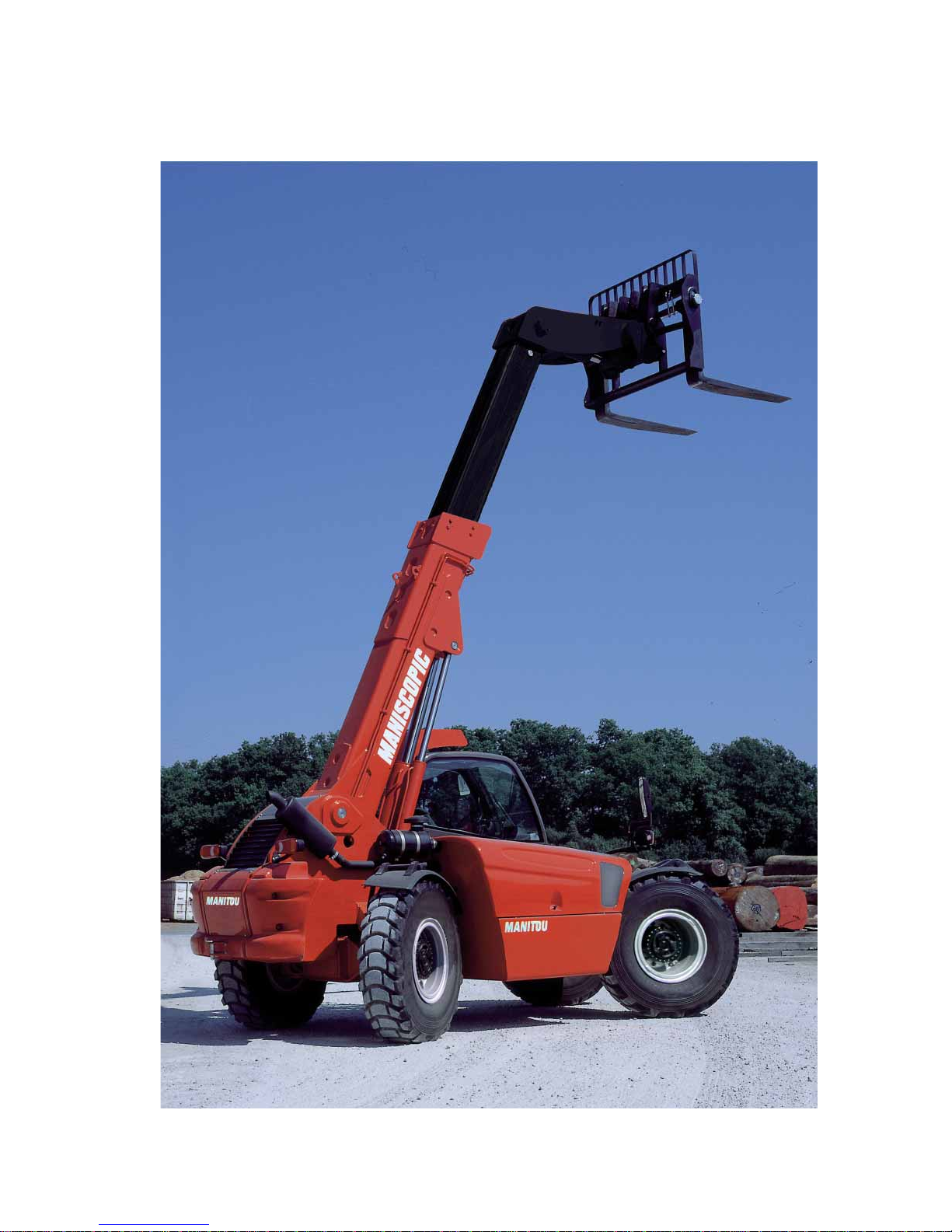
MHT 7140 T-E3
Page 5
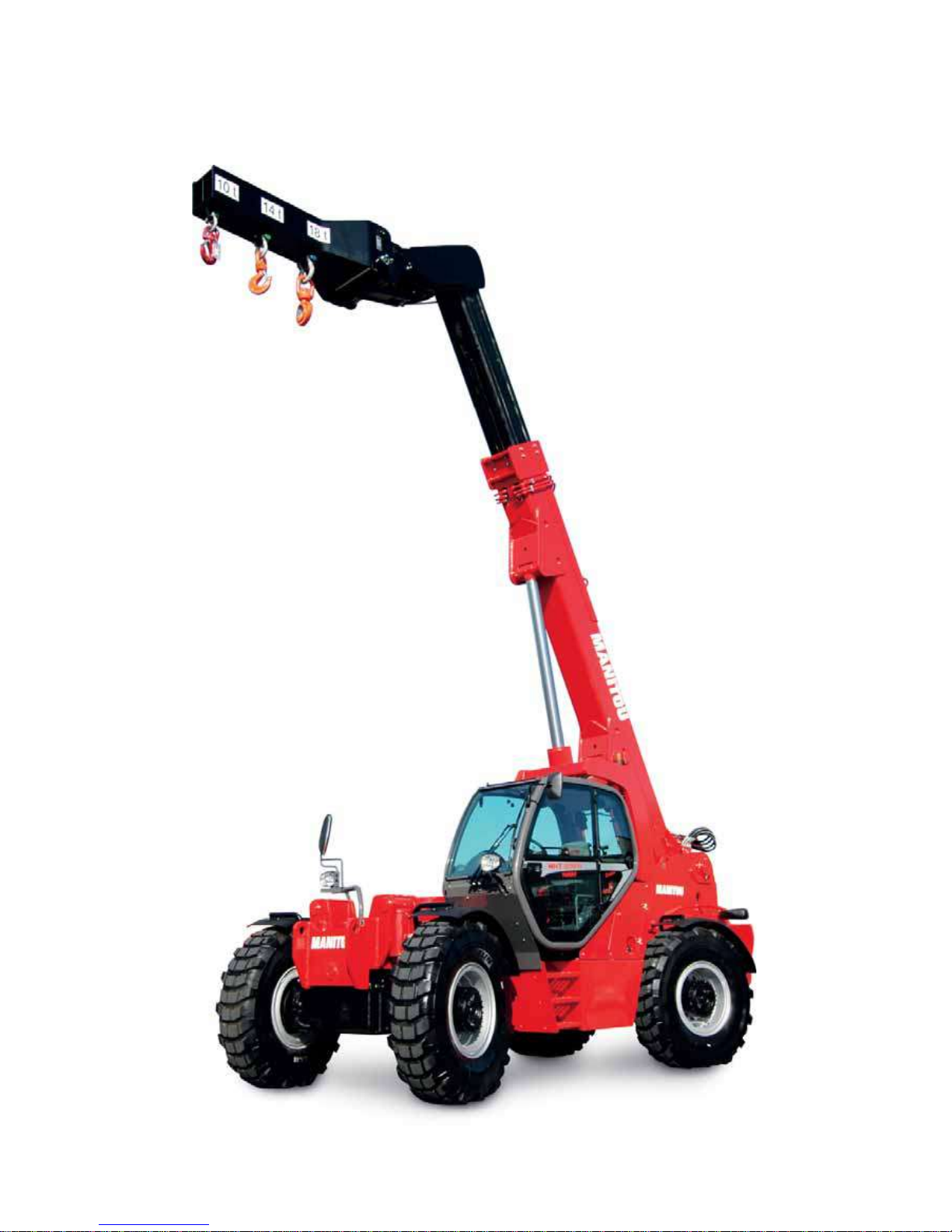
MHT 10180 LT-E3
Page 6
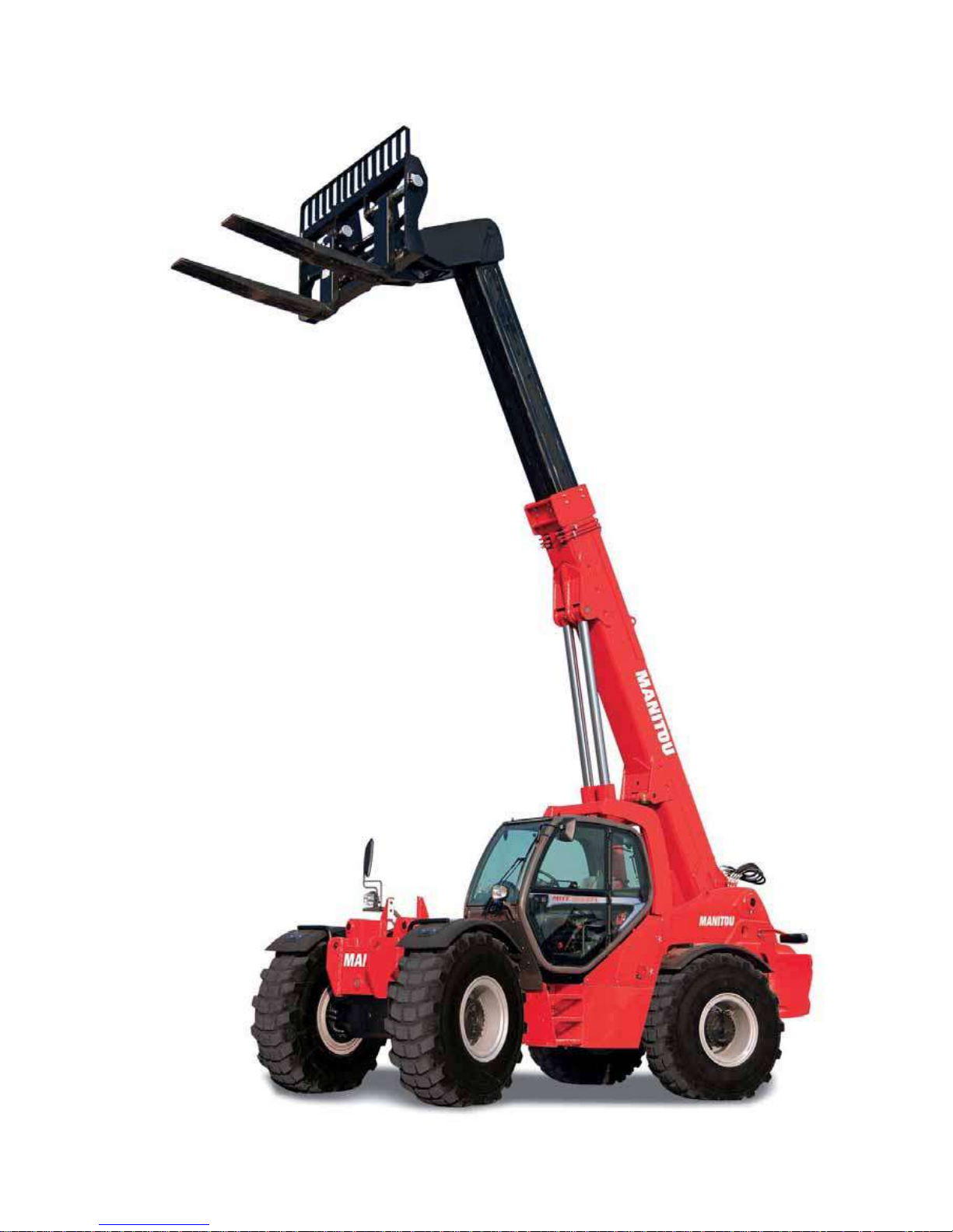
MHT 10225 LT-E3
Page 7

1-1
1 - OPERATING
AND SAFETY
INSTRUCTIONS
Page 8

1-2
Page 9

1-3
TABLE OF CONTENTS
INSTRUCTIONS TO THE COMPANY MANAGER
THE SITE
THE OPERATOR
THE LIFT TRUCK
A - THE LIFT TRUCK’S SUITABILITY FOR THE JOB
B - ADAPTATION OF THE LIFT TRUCK TO STANDARD ENVIRONMENTAL CONDITIONS
C - MODIFICATION OF THE LIFT TRUCK
D - FRENCH ROAD TRAFFIC RULES
(or see current legislation in other countries)
THE INSTRUCTIONS
THE MAINTENANCE
INSTRUCTIONS FOR THE OPERATOR
PREAMBULE
GENERAL INSTRUCTIONS
A - OPERATOR’S MANUAL
B - AUTHORIZATION FOR USE IN FRANCE
(or see current legislation in other countries)
C - MAINTENANCE
D - MODIFICATION OF THE LIFT TRUCK
E - LIFTING PEOPLE
OPERATING INSTRUCTIONS UNLADEN AND LADEN
A - BEFORE STARTING THE LIFT TRUCK
B - DRIVER’S OPERATING INSTRUCTIONS
C - ENVIRONMENT
D - VISIBILITY
E - STARTING THE LIFT TRUCK
F - DRIVING THE LIFT TRUCK
G - STOPPING THE LIFT TRUCK
H - DRIVING THE LIFT TRUCK ON THE PUBLIC HIGHWAY
(or see current legislation in other countries)
INSTRUCTIONS FOR HANDLING A LOAD
A - CHOICE OF ATTACHMENTS
B - MASS OF LOAD AND CENTRE OF GRAVITY
C - LONGITUDINAL STABILITY LIMITER AND WARNING DEVICE
D - TRANSVERSE ATTITUDE OF THE LIFT TRUCK
E - TAKING UP A LOAD ON THE GROUND
F - TAKING UP AND LAYING A HIGH LOAD ON TYRES
G - TAKING UP AND LAYING DOWN A SUSPENDED LOAD
H - TRAVELLING WITH A SUSPENDED LOAD
PLATFORM OPERATING INSTRUCTIONS
A - AUTHORISATION FOR USE
B - SUITABILITY OF THE PLATFORM FOR THE JOB
C - PRECAUTIONS WHEN USING THE PLATFORM
D - USING THE PLATFORM
E - ENVIRONMENT
F - MAINTENANCE
INSTRUCTIONS FOR USING THE RADIO-CONTROL
MAINTENANCE INSTRUCTIONS OF THE LIFT TRUCK
GENERAL INSTRUCTIONS
MAINTENANCE
LUBRICANT AND FUEL LEVELS
HYDRAULIC
ELECTRICITY
WELDING
WASHING THE LIFT TRUCK
IF THE LIFT TRUCK IS NOT TO BE USED FOR A LONG TIME
INTRODUCTION
PREPARING THE LIFT TRUCK
PROTECTING THE I.C. ENGINE
PROTECTING THE LIFT TRUCK
BRINGING THE LIFT TRUCK BACK INTO SERVICE
1 - 4
1 - 4
1 - 4
1 - 4
1 - 4
1 - 4
1 - 5
1 - 5
1 - 5
1 - 5
1 - 6
1 - 6
1 - 6
1 - 6
1 - 6
1 - 6
1 - 6
1 - 7
1 - 8
1 - 8
1 - 8
1 - 9
1 - 9
1 - 10
1 - 10
1 - 11
1 - 12
1 - 14
1 - 14
1 - 14
1 - 14
1 - 15
1 - 15
1 - 16
1 - 18
1 - 18
1 - 19
1 - 19
1 - 19
1 - 19
1 - 19
1 - 20
1 - 20
1 - 21
1 - 22
1 - 22
1 - 22
1 - 22
1 - 22
1 - 22
1 - 23
1 - 23
1 - 24
1 - 24
1 - 24
1 - 24
1 - 24
1 - 25
Page 10

1-4
INSTRUCTIONS TO THE COMPANY MANAGER
THE SITE
- Proper management of lift truck’s area of travel will reduce the risk of accidents:
. ground not unnecessarily uneven or obstructed,
. no excessive slopes,
. pedestrian traffic controlled, etc.
THE OPERATOR
- Only qualified, authorized personnel can use the lift truck. This authorization is given in writing by the appropriate person in the
establishment with respect to the use of lift trucks and must be carried permanently by the operator.
On the basis of experience, there are a number of possible situations in which operating the lift truck is contra-indicated. Such foreseeable abnormal uses,
the main ones being listed below, are strictly forbidden.
- The foreseeable abnormal behaviour resulting from ordinary neglect, but does not result from any wish to put the machinery to any improper use.
- The reflex reactions of a person in the event of a malfunction, incident, fault, etc. during operation of the lift truck.
- Behaviour resulting from application of the «principle of least action» when performing a task.
- For certain machines, the foreseeable behaviour of such persons as: apprentices, teenagers, handicapped persons, trainees tempted to drive a lift
truck, operator tempted to operate a truck to win a bet, in competition or for their own personal experience.
The person in charge of the equipment must take these criteria into account when assessing whether or not a person will makea suitable driver.
THE LIFT TRUCK
A - THE TRUCK’S SUITABILITY FOR THE JOB
- MANITOU has ensured that this lift truck is suitable for use under the standard operating conditions defined in this operator’s manual,
with a STATIC test coefficient OF 1.33 and a DYNAMIC test coefficient OF 1, as specified in harmonized norm EN 1459 for variable
range trucks.
- Before commissioning, the company manager must make sure that the lift truck is appropriate for the work to be done, and perform
certain tests (in accordance with current legislation).
B - ADAPTATION OF THE LIFT TRUCK TO STANDARD ENVIRONMENTAL CONDITIONS
- In addition to series equipment mount ed on your lift truck, many options are available, such as: road lighting, stop lights, flashing light,
reverse lights, reverse buzzer alarm, front light, rear light, light at the jib head, etc… (as model of lift truck).
- The operator must take into account the operating conditions to define the lift truck’s signalling and lighting equipment.
Contact your dealer.
- Take into account climatic and atmospheric conditions of the site of utilisation.
. Protection against frost (see: 3 - MAINTENANCE: LUBRICANTS AND FUEL).
. Adaptation of lubricants (ask your dealer for information).
. I.C. engine filtration (see: 3 - MAINTENANCE: FILTERS CARTRIDGES AND BELTS).
For operation under average climatic conditions, i.e.: between - 15 °C and + 35 °C, correct levels of lubricants in all the circuits are checked in production.
For operation under more severe climatic conditions, before starting up, it is necessary to drain all the circuits, then ensure correct levels of lubricants using
lubricants properly suited to the relevant ambient temperatures. It is the same for the cooling liquid.
- A lif t truck operating in an area without fire extinguishing equipment must be equipped with an individual extinguisher. There are
solutions, consult your dealer.
Your lift truck is designed for outdoor use under normal atmospheric conditions and indoor use in suitably aerated and ventilated premises. It is prohibited to
use the lift truck in areas where there is a risk of fire or which are potentially explosive (e.g. Refineries, fuel or gas depots, stores of inflammable products…).
For use in these areas, specific equipment is available (ask your dealer for information).
- Our trucks comply with Directiv e 2004/108/EC concerning electromagnetic compatibility (EMC), and with the corresponding har monized
norm EN 12895. Their proper operation is no longer guaranteed if they are used within areas in which the electromagnetic fields exceed
the limit specified by that norm (10 V/m).
- Directive 2002/44/EC requires company managers t o not e xpose their emplo y ees t o e xcessiv e vibration doses. There is no recog nized
code of measurement for comparing the machines of different manufacturers. The actual doses received can therefore be measured
only under actual operating conditions at the user's premises.
- The following are some tips for minimizing these vibration doses:
• Select the most suitable lift truck and attachment for the intended use.
• Adapt the seat adjustment to the operator's weight (according to lift truck model) and maintain it in good condition, as well
as the cab suspension. Inflate the tires in accordance with recommendations.
• Ensure that the operators adapt their operating speed to suit the conditions on site.
• As far as possible, arrange the site in such a way as to provide a flat running surface and remove obstacles and harmful
potholes.
Page 11

1-5
C - MODIFICATION OF THE LIFT TRUCK
- For your safety and that of others, you must not change the structure and settings of the various components used in your lift truck
(hydraulic pressure, calibrating limiters, I.C. engine speed, addition of extra equipment, addition of counterweight, unapproved
attachments, alarm systems, etc.) yourself. In this event, the manufacturer cannot be held responsible.
D - FRENCH ROAD TRAFFIC RULES
(or see current legislation in other countries)
- Only one certificate of conformity is issued. It must be kept in a safe place.
THE INSTRUCTIONS
- The operator’s manual must always be in good condition and kept in the place provided on the lift truck and in the language used by
the operator.
- The operator’s manual and any plates or stickers which are no longer legible or are damaged, must be replaced immediately.
THE MAINTENANCE
- Maintenance or repairs other than those detailed in part: 3 - MAINTENANCE must be carried out by qualified personnel (consult your
dealer) and under the necessary safety conditions to maintain the health of the operator and any third party.
Your lift truck must be inspected periodically to ensure that it remains in compliance. The frequency of this inspection is defined by current legislation in the
country in which the lift truck is used.
Page 12

1-6
INSTRUCTIONS FOR THE OPERATOR
PREAMBLE
WHENEVER YOU SEE THIS SYMBOL IT MEANS:
WARNING ! BE CAREFUL ! YOUR SAFETY OR THE SAFETY OF THE LIFT TRUCK IS AT RISK.
The risk of accident while using, servicing or repairing your lift truck can be restricted if you follow the safety instructions and safety measures detailed in
these instruction.
- Only the operations and manœuvres described in these operator’s manual must be performed. The manufacturer cannot predict
all possible risky situations. Consequently, the safety instructions given in the operator’s manual and on the lift truck itself are not
exhaustive.
- At any time, as an operator, you must envisage, within reason, the possible risk to yourself, to others or to the lift truck itself when you
use it.
Failure to respect the safety and operating instructions, or the instructions for repairing or servicing your lift truck may lead to serious, even fatal accident.
GENERAL INSTRUCTIONS
A - OPERATOR’S MANUAL
- Read the operator’s manual carefully.
- The operator’s manual must always be in good condition and in the place provided for it on the lift truck.
- You must report any plates and stickers which are no longer legible or which are damaged.
B - AUTHORISATION FOR USE IN FRANCE
(or see current legislation in other countries)
- Only qualified, authorized personnel can use the lift truck. This authorization is given in writing by the appropriate person in the
establishment with respect to the use of lift trucks and must be carried permanently by the operator.
- The operator is not competent to authorise the driving of the lift truck by another person.
C - MAINTENANCE
- The operator must immediately advise his superior if his lift truck is not in good working order or does not comply with the safety notice.
- The operator is prohibited from carrying out any repairs or adjustments himself, unless he has been trained for this purpose. He must keep
the lift truck properly cleaned if this is among his responsibilities.
- The operator must carry out daily maintenance (see: 3 - MAINTENANCE: A - DAILY OR EVERY 10 HOURS SERVICE).
- The operator must ensure tyres are adapted to the nature of the ground (see area of the contact surface of the tyres in the chapter:
2 - DESCRIPTION: FRONT AND REAR TYRES). There are optional solutions, consult your dealer.
. SAND tyres.
. LAND tyres.
. Snow chains.
Do not use the lift truck if the tyres are incorrectly inflated, damaged or excessively worn, because this could put your own safety or that of others at risk, or
cause damage to the lift truck itself. The fitting of foam inflated tyres is prohibited and is not guaranteed by the manufacturer, excepting prior authorisation.
D - MODIFICATION OF THE LIFT TRUCK
- For your safety and that of others, you must not change the structure and settings of the various components used in your lift truck
(hydraulic pressure, calibrating limiters, I.C. engine speed, addition of extra equipment, addition of counterweight, unapproved
attachments, alarm systems, etc.) yourself. In this event, the manufacturer cannot be held responsible.
Page 13

1-7
E - LIFTING PEOPLE
- The use of working equipment and load lifting attachments to lift people is:
• either forbidden
• or authorized e xceptionally and under certain conditions (see current regulations in
the country in which the lift truck is used).
- The pictogram posted at the operator station reminds you that:
• Left-hand column
- It is forbidden to lift people, with any kind of attachment, using a non PLATFORM-
fitted lift truck.
• Right-hand column
- With a PLATFORM-fitted lift truck, people can only be lifted using platforms
designed by MANITOU for the purpose.
- MANITOU sells equipment specifically designed for lifting people (OPTION PLATFORM lift
truck, contact your dealer).
Page 14

1-8
OPERATING INSTRUCTIONS UNLADEN AND LADEN
A - BEFORE STARTING THE LIFT TRUCK
- Carry out daily maintenance (see: 3 - MAINTENANCE: A - DAILY OR EVERY 10 HOURS SERVICE).
- Make sure the lights, indicators and windscreen wipers are working properly.
- Make sure the rear view mirrors are in good condition, clean and properly adjusted.
- Make sure the horn works.
B - DRIVER’S OPERATING INSTRUCTIONS
- Whate ver his experience, the operator is advised t o familiarize himself with the position and operation of all the controls and instruments
before operating the lift truck.
- Wear clothes suited for driving the lift truck, avoid loose clothes.
- Make sure you have the appropriate protective equipment for the job to be done.
- Prolonged exposure to high noise lev els may cause hearing pr oblems. It is recommended to w ear ear muffs to prot ect against e xcessive
noise.
- Always face the lift truck when getting into and leaving the driving seat and use the handle(s) provided for this purpose. Do not jump
out of the seat to get down.
- Always pay attention when using the lift truck. Do not listen to the radio or music using headphones or earphones.
- Never operate the lift truck when hands or feet are wet or soiled with greasy substances.
- For increased comfort, adjust the seat to your requirements and adopt the correct position in the driver’s cab.
Under no circumstances must the seat be adjusted while the lift truck is moving.
- The operator must always be in his normal position in the driver’s cab. It is prohibited to have arms or legs, or generally any part of the
body, protruding from the driver’s cab of the lift truck.
- The safety belt must be worn and adjusted to the operator’s size.
- The control units must never in any event be used for any other than their intended purposes (e.g. climbing onto or down from the lift
truck, portmanteau, etc.).
- If the control components are fitted with a forced operation (lever lock) device, it is forbidden t o lea ve the cab without f irst putting these
controls in neutral.
- It is prohibited to carry passengers either on the lift truck or in the cab.
Page 15
1-9
C - ENVIRONMENT
- Comply with site safety regulations.
- If you have to use the lift truck in a dark area or at night, make sure it is equipped with working lights.
- During handling operations, make sure that no one is in the way of the lift truck and its load.
- Do not allow anybody to come near the working area of the lift truck or pass beneath an elevated load.
- When using the lift truck on a transverse slope, before lifting the jib, follow the instructions given in the paragraph: INSTRUCTIONS FOR
HANDLING A LOAD: D - TRANSVERSE ATTITUDE OF THE LIFT TRUCK.
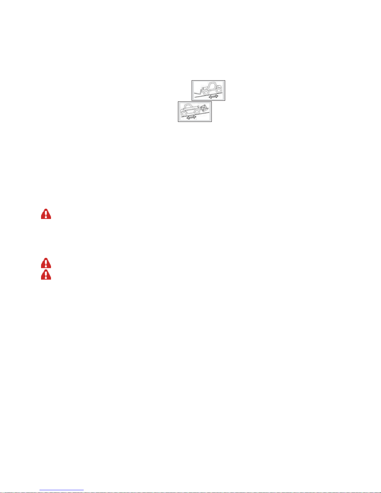
- Travelling on a longitudinal slope:
• Drive and brake gently.
• Moving without load: Forks or attachment facing downhill.
• Moving with load: Forks or attachment facing uphill.
- Take into account the lift truck’s dimensions and its load before trying to negotiate a narrow or low passageway.
- Never move onto a loading platform without having first checked:
• That it is suitably positioned and made fast.
• That the unit to which it is connected (wagon, lorry, etc.) will not shift.
• That this platform is prescribed for the total weight of the lift truck to be loaded.
• That this platform is prescribed for the size of the lift truck.
- Never move onto a foot bridge, floor or freight lift, without being certain that they are prescribed for the weight and size of the lift truck
to be loaded and without having checked that they are in sound working order.
- Be careful in the area of loading bays, trenches, scaffolding, soft land and manholes.
- Make sure the ground is stable and firm under the wheels and/or stabilizers before lifting or removing the load. If necessary, add
sufficient wedging under the stabilizers.
- Make sure that the scaffolding, loading platform, pilings or ground is capable of bearing the load.
- Never stack loads on uneven ground, they may tip over.
If the load or the attachment must remain above a structure for a long time, there is the risk that it will rest on the structure because of the jib descending
owing to the oil in the cylinders cooling down.
To eliminate this risk:
- Regularly check the distance between the load or the attachment and the structure and readjust this if necessary.
- If possible use the lift truck at an oil temperature as close as possible to ambient temperature.
- In the case of work near aerial lines, ensure that the safety distance is sufficient between the working area of the lift truck and the
aerial line.
You must consult your local electrical agency. You could be electrocuted or seriously injured if you operate or park the lift truck too close to power cables.
In the event of high winds, do not carr y out handling work that jeopardizes the stability of the lift truck and its load, particularly if the load catches the wind
badly.
D - VISIBILITY
- The safety of people within the lift truck’s working area, as well as that of the lift truck itself and the operator are depend on good
operator visibility of the lift truck’s immediate vicinity in all situations and at all times.
- This lift truck has been designed to allow good operator visibility (direct or indirect by means of rear-view mirrors) of the immediate
vicinity of the lift truck while traveling with no load and with the jib in the transport position.
- Special precautions must be taken if the size of the load restricts visibility towards the front:
- moving in reverse,
- site layout,
- assisted by a person directing the maneuver (while standing outside the truck’s area of travel), making sure to keep this person
clearly in view at all times.
- in any case, avoid reversing over long distances.
- Certain special accessories may require the truck to travel with the jib in the raised position. In such cases, visibility on the right hand
side is restricted, and special precautions must be taken:
- site layout,
- assisted by a person directing the maneuver (while standing outside the truck’s area of travel).
- If visibility of your road is inadequate, ask someone to assist by directing the maneuver (while standing outside the truck’s area of
travel), making sure to keep this person clearly in view at all times.
- Keep all components affecting visibility in a clean, properly adjusted state and in good working order (e.g. windscreens, windows,
windscreen wipers, windscreen washers, driving and work lights, rear-view mirrors).
Page 16

1-10
E - STARTING THE LIFT TRUCK
SAFETY INSTRUCTIONS
The lift truck must only be started up or maneuvered when the operator is sitting in the driver’s cab, with his seat belt adjusted and fastened.
- Never try to start the lif t truck by pushing or towing it. Such operation may cause severe damage to the transmission. If necessary, to
tow the lift truck in an emergency, the transmission must be placed in the neutral position (see: 3 - MAINTENANCE: G - OCCASIONAL
MAINTENANCE).
- If using an emergency battery for start-up, use a battery with the same characteristics and respect battery polarity when connecting it.
Connect at first the positive terminals before the negative terminals.
Failure to respect polarity between batteries can cause serious damage to the electrical circuit. The electrolyte in the battery may produce an explosive gas.
Avoid flames and generation of sparks close to the batteries. Never disconnect a battery while it is charging.
INSTRUCTIONS
- Check the closing and locking of the hood(s).
- Check that the cab door is closed.
- Check that the forward/reverse selector is in neutral.
- Turn the ignition key to the position I to activate the electrical system and the preheat.
- Whenever you switch on the lift truck, perform the automatic check on the longitudinal stability limiter and warning device system (see:
2 - DESCRIPTION: INSTRUMENTS AND CONTROLS). Do not use the lift truck if it does not conform to the regulations.
- Check the fuel level on the indicator.
- Turn the ignition key fully: the I.C. engine should then start. Release the ignition key and let the I.C. engine run at idle.
- Do not engage the starter motor for more than 15 seconds and carry out the preheating between unsuccessful attempts.
- Make sure all the signal lights on the control instrument panel are off.
- Check all control instruments when the I.C. engine is warm and at regular intervals during use, so as to quickly detect any f aults and t o
be able to correct them without any delay.
- If an instrument does not show the correct display, stop the I.C. engine and immediately carry out the necessary operations.
F - DRIVING THE LIFT TRUCK
SAFETY INSTRUCTIONS
Operators’ attention is drawn to the risks involved in using the lift truck, in particular:
- Risk of losing control.
- Risk of losing lateral and frontal stability of the lift truck.
The operator must remain in control of the lift truck.
In the event of the lift truck overturning, do not try to leave the cabin during the incident. YOUR BEST PROTECTION IS TO STAY FASTENED IN THE CABIN.
- Observe the company’s traffic regulations or, by default, the public highway code.
- Do not carry out operations which exceed the capacities of your lift truck or attachments.
- Always drive the lift truck with the forks or attachment to the transport position, i.e. at 300 mm from the ground, the jib retracted and
the carriage sloping backwards.
- Only carry loads which are balanced and properly anchored to avoid any risk of a load falling off.
- Ensure that palettes, cases, etc, are in good order and suitable for the load to be lifted.
- Familiarise yourself with the lift truck on the terrain where it will be used.
- Ensure that the service brakes are working properly.
- The loaded lift truck must not travel at speeds in excess of 12 km/h.
- Drive smoothly at an appropriate speed for the operating conditions (land configuration, load on the lift truck).
- Do not use the hydraulic jib controls when the lift truck is moving.
- Never change the steering mode whilst driving.
- Do not manoeuvre the lif t truck with the jib in the raised position unless under exceptional circumstances and then with extreme
caution, at very low speed and using gentle braking. Ensure that visibility is adequate.
- Take bends slowly.
- In all circumstances make sure you are in control of your speed.
- On damp, slippery or uneven terrain, drive slowly.
- Brake gently, never abruptly.
- Only use the lift truck’s forward/reverse selector from a stationary position and never do so abruptly.
- Do not drive with your foot on the brake pedal.
- Always remember that hydrostatic type steering is extremely sensitive t o movement of the st eering wheel, so turn it gently and not jerkily .
- Never leave the I.C. engine on when the lift truck is unattended.
- Do not leave the cab when the lift truck has a raised load.
- Look where you are going and always make sure you have good visibility along the route.
Page 17

1-11
- Use the rear-view mirrors frequently.
- Drive round obstacles.
- Never drive on the edge of a ditch or steep slope.
- It is dangerous to use two lift trucks simultaneously to handle heavy or voluminous loads, since this operation requires particular
precautions to be taken. It must only be used exceptionally and after risk analysis.
- The ignition switch has an emergency stop mechanism in case of an operating anomaly occurring in the case of lift trucks not fitted with
a punch-operated cut-out.
INSTRUCTIONS
- Always drive the lift truck with the forks or attachment to the transport position, i.e. at 300 mm from the ground, the jib retracted and
the carriage sloping backwards.
- For lift trucks with gearboxes, use the recommended gear (see: 2 - DESCRIPTION: INSTRUMENTS AND CONTROLS).
- Select the steering mode appropriate for its use and/or working conditions (see: 2 - DESCRIPTION: INSTRUMENTS AND CONTROLS) (as
model of lift truck).
- Release the parking brake.
- Shift the forward/reverse selector to the selected direction of travel and accelerate gradually until the lift truck moves off.
G - STOPPING THE LIFT TRUCK
SAFETY INSTRUCTIONS
- Never leave the ignition key in the lift truck during the operator’s absence.
- When the lift truck is stationary, or if the operator has t o leave his cab (e ven f or a moment), place the forks or attachmen t on the ground,
apply the parking brake and place the forward/reverse selector in neutral.
- Make sure that the lift truck is not stopped in any position that will interfere with the traffic flow and at less than one meter from the
track of a railway.
- In the event of prolonged parking on a site, protect the lift truck from bad weather, particularly from frost (check the level of antifreeze),
close and lock all the lift truck accesses (doors, windows, cowls…).
INSTRUCTIONS
- Park the lift truck on flat ground or on an incline lower than 15 %.
- Set the forward/reverse selector to neutral.
- Apply the parking brake.
- For lift trucks with gearboxes, place the gear lever in neutral.
- Retract entirely the jib.
- Lower the forks or attachment to rest on the ground.
- When using an attachment with a grab or jaws, or a bucket with hydraulic opening, close the attachment fully.
- Before stopping the lift truck after a long working period, leave the I.C. engine idling for a few moments, to allow the coolant liquid and
oil to lower the temperature of the I.C. engine and transmission. Do not forget this precaution, in the event of frequent stops or warm
stalling of the I.C. engine, or else the temperature of certain parts will rise significantly due to the stopping of the cooling system, with
the risk of badly damaging such parts.
- Stop the I.C. engine with the ignition switch.
- Remove the ignition key.
- Lock all the accesses to the lift truck (doors, windows, cowls…).
Page 18

1-12
H - DRIVING THE LIFT TRUCK ON THE PUBLIC HIGHWAY
(or see current legislation in other countries)
SAFETY INSTRUCTIONS
- Operators driving on the public highway must comply with current highway code legislation.
- The lift truck must comply with current road legislation. If necessary, there are optional solutions. Contact your dealer.
INSTRUCTIONS
- Make sure the revolving light is in place, switch it on and verify its operation.
- Make sure the lights, indicators and windscreen wipers are working properly.
- Switch off the working headlights if the lift truck is fitted with them.
- Select the steering mode “HIGHWAY TRAFFIC” (as model of lift truck) (see: 2 - DESCRIPTION: INSTRUMENTS AND CONTROLS).
- Retract entirely the jib and put the attachment at 300 mm from the ground.
- Place the slope correctors in the central position, i.e. the transverse shaft of the axles parallel to the chassis (as model of lift truck).
- Lift up the stabilizers to the maximum and turn the blocks inwards (as model of lift truck).
Never move in neutral (forward/reverse selector or gear lever in neutral or transmission cut-off button pressed) to preserve the lift truck engine brake. Failure
to respect this instruction on a slope will lead to excessive speed which may make the lift truck uncontrollable (steering, brakes) and cause serious mechanical
damage.
Page 19

1-13
DRIVING THE LIFT TRUCK WITH A FRONT-MOUNTED ATTACHMENT
- You must comply with current regulations in your country, co vering the possibility of driving on the public highway with a front-mounted
attachment on your lift truck.
- If road legislation in your country authorizes circulation with a front-mounted attachment, you must at least:
• Protect and report any sharp and/or dangerous edges on the attachment (see: 4 - ADAPTABLE ATTACHMENTS IN OPTION ON
THE RANGE: ATTACHMENT SHIELDS).
• The attachment must not be loaded.
• Make sure that the attachment does not mask the lighting range of the forward lights.
• Make sure that current legislation in your country does not require other obligations.
OPERATING THE LIFT TRUCK WITH A TRAILER
- For using a trailer, observe the regulations in force in your country (maximum travel speed, braking, maximum weight of trailer, etc.).
- Do not forget to connect the trailer’s electrical equipment to that of the lift truck.
- The trailer’s braking system must comply with current legislation.
- If pulling a trailer with assisted braking, the tractor lift truck must be equipped with a trailer braking mechanism. In this case, do not
forget to connect the trailer braking equipment to the lift truck.
- The vertical force on the towing hook must not exceed the maximum authorised by the manufacturer (consult the manufacturer’s plat e
on your lift truck).
- The authorised gross vehicle weight must not exceed the maximum weight authorised by the manufacturer (see: 2 - DESCRIPTION:
CHARACTERISTICS).
IF NECESSARY, CONSULT YOUR DEALER.
Page 20
1-14
INSTRUCTIONS FOR HANDLING A LOAD
A - CHOICE OF ATTACHMENTS
- Only attachments approved by MANITOU can be used on its lift trucks.
- Make sure the attachment is appropriate for the work to be done (see: 4 - ADAPTABLE ATTACHMENTS IN OPTION ON THE RANGE).
- If the lift truck is equipped with the Single side-shif t carriage OPTION (TSDL), use only the authorised attachments (see: 4 - ADAPTABLE
ATTACHMENTS IN OPTION ON THE RANGE).
- Make sure the attachment is correctly installed and locked onto the lift truck carriage.
- Make sure that your lift truck attachments work properly.
- Comply with the load chart limits for the lift truck for the attachment used.
- Do not exceed the rated capacity of the attachment.
- Never lift a load in a sling without the attachment provided for the purpose, as the sling risks to slip (see: INSTR UCTIONS FOR HANDLING
A LOAD: H - TAKING UP AND LAYING DOWN A SUSPENDED LOAD).
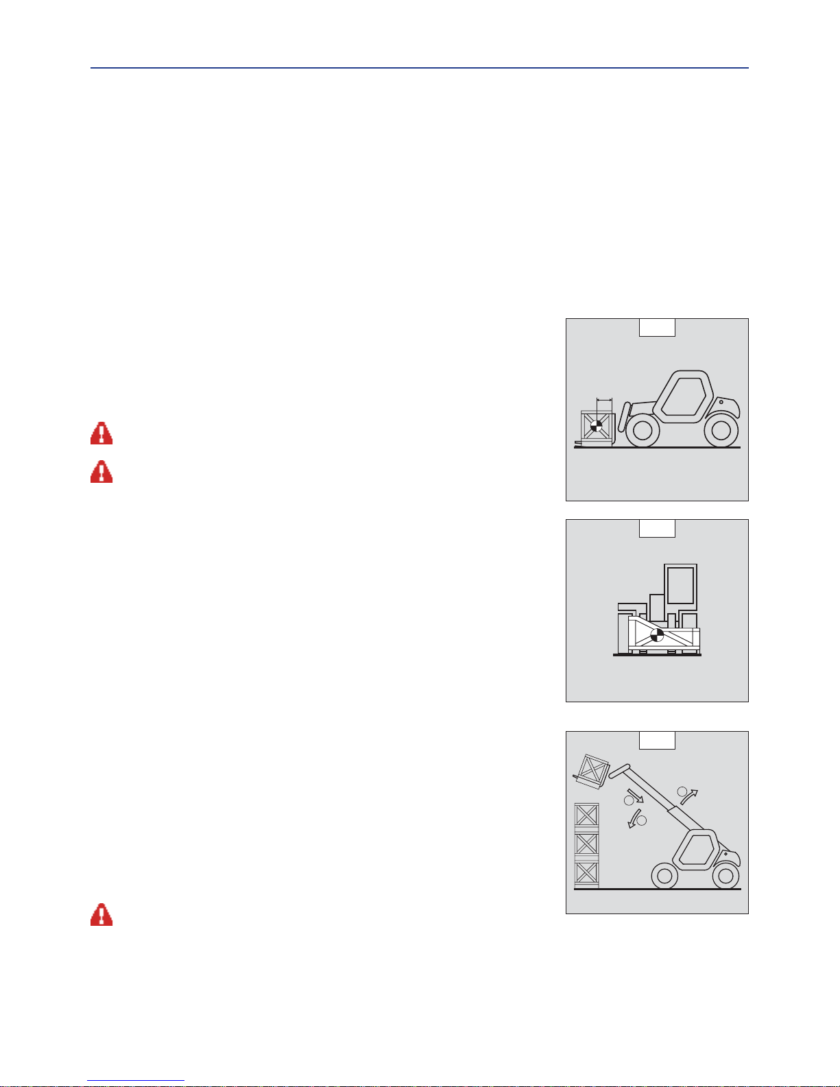
B - MASS OF LOAD AND CENTRE OF GRAVITY
- Before taking up a load, you must know its mass and its centre of gravity.
- The load chart for your lift truck is valid for a load in which the longitudinal position of the
centre of gravity is 500 mm from the base of the forks (fig. B1). For a higher centre of gravity,
contact your dealer.
- For irregular loads, determine the transverse centre of gravity before any movement (fig. B2)
and set it in the longitudinal axis of the lift truck.
It is forbidden to move a load heavier than the effective capacity defined on the lift truck load chart.
For loads with a moving centre of gravity (e.g. liquids), take account of the variations in the centre of gravity
in order to determine the load to be handled and be vigilant and take extra care to limit these variations as
far as possible.
C - LONGITUDINAL STABILITY LIMITER AND WARNING DEVICE
This device gives an indication of the longitudinal stability of the lift truck, and limits hydraulic
movements in order to ensure this stability, at least under the following operating conditions:
• when the lift truck is at a standstill,
• when the lift truck is on firm, stable and consolidated ground,
• when the lift truck is performing handling and placing operations.
- Move the jib very carefully when approaching the authorized load limit (see: 2 - DESCRIPTION:
INSTRUMENTS AND CONTROLS).
- Always watch this device during handling operations.
- In the event that "AGGRA VA TING" hydraulic mov ements are cut-off, only perform de-aggravating
hydraulic movements in the follo wing order (fig. C): if necessary, raise the jib (1), retract the jib
as far as possible (2) and lower the jib (3) to set down the load.
The instrument reading may be erroneous when the steering is at its maximum limit or the rear axle
oscillated to its limit. Before lifting a load, make sure that the lift truck is not in either of these situations.
500 mm
B1
B2
1
2
3
C
Page 21
1-15
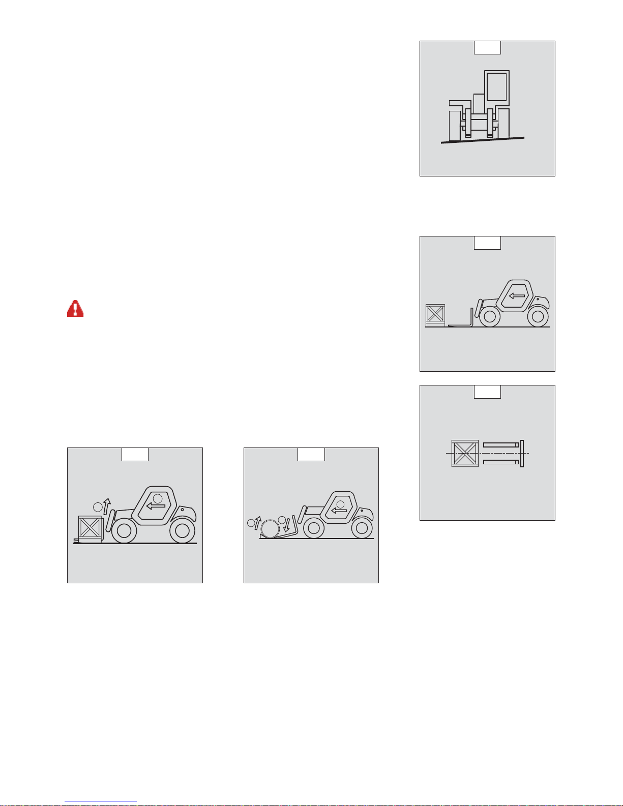
D - TRANSVERSE ATTITUDE OF THE LIFT TRUCK
Depending on the model of lift truck
The transverse attitude is the transverse slope of the chassis with respect to the horizontal.
Raising the jib reduces the lift truck’s lateral stability. The transverse attitude must be set with
the jib in down position as follows:
1 - LIFT TRUCK WITHOUT SLOPE CORRECTOR USED ON TYRES
- Position the lift truck so that the bubble in the level is between the two lines (see: 2 -
DESCRIPTION: INSTRUMENTS AND CONTROLS).
2 - LIFT TRUCK WITH SLOPE CORRECTOR USED ON TYRES
- Correct the slope using the hydraulic control and verify the horizontality via the level. The
bubble in the level must be between the two lines (see: 2 - DESCRIPTION: INSTRUMENTS AND CONTROLS).
E - TAKING UP A LOAD ON THE GROUND
- Approach the lift truck perpendicular to the load, with the jib retracted and the forks in a
horizontal position (fig. E1).
- Adjust the fork spread and centering in connection with the load (fig. E2) (optional solutions
exist, consult your dealer).
- Never lift a load with a single fork.
Beware of the risks of trapping or squashing limbs when manually adjusting the forks.
- Move the lift truck forward slowly (1) and bring the forks to stop in front of the load (fig. E3), if
necessary, slightly lift the jib (2) while taking up the load.
- Bring the load into the transport position.
- Tilt the load far enough backwards to ensure stability (loss of load on braking or going downhill).
FOR A NON-PALLETIZED LOAD
- Tilt the carriage (1) forwards and move the lift truck slowly forwards (2), to insert the fork
under the load (fig. E4) (block the load if necessary).
- Continue to move the lift truck forwards (2) tilting the carriage (3) (fig. E4) backwards to
position the load on the forks and check the load’s longitudinal and lateral stability.
D1
E1
E2
1
2
E3
1
2
3
E4
Page 22
1-16
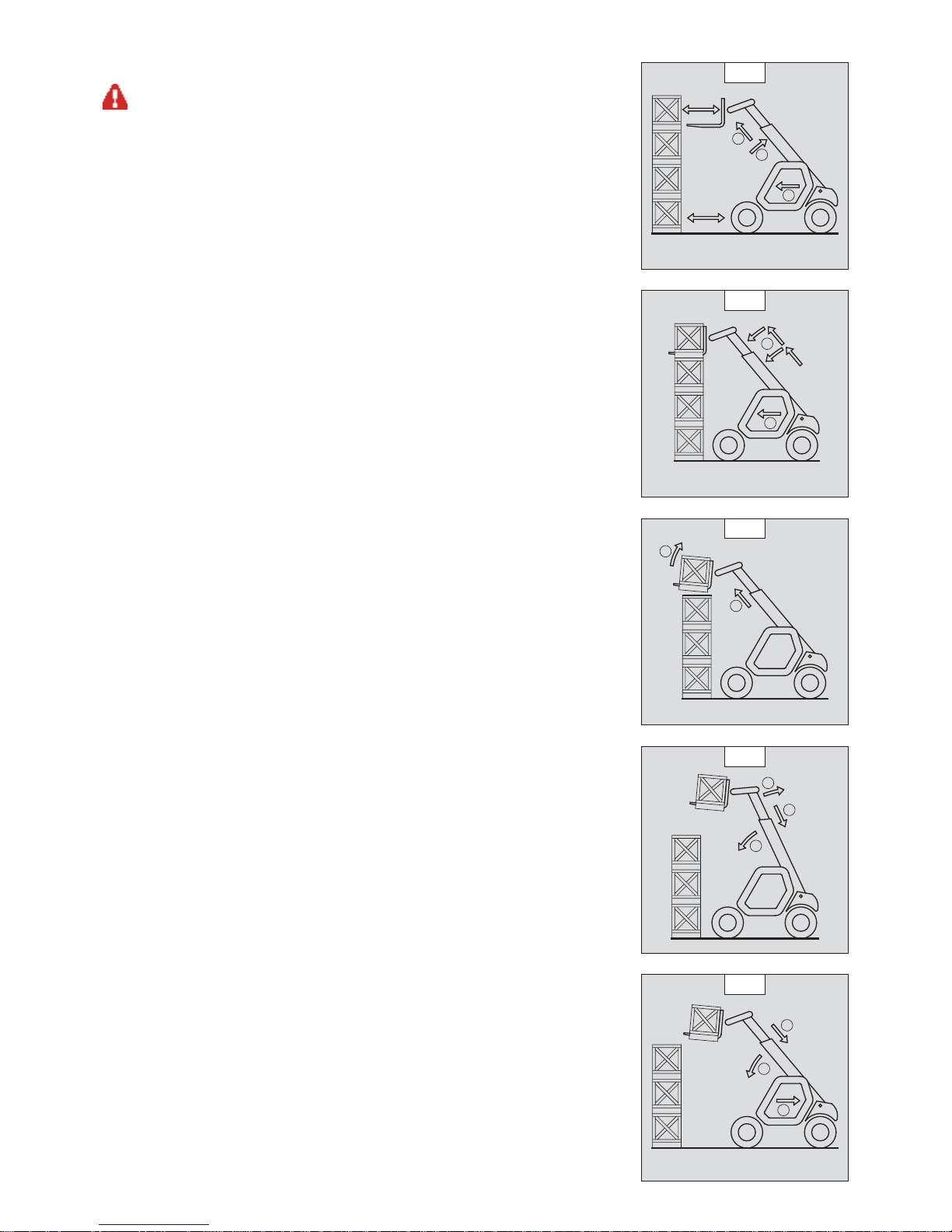
F - TAKING UP AND LAYING A HIGH LOAD ON TYRES
Y ou must not raise the jib if you have not checked the transverse attitude of the lift truck (see: INSTRUCTIONS
FOR HANDLING A LOAD: D - TRANSVERSE ATTITUDE OF THE LIFT TRUCK).
REMINDER: Make sure that the following operations can be performed with good visibility (see:
OPERATIONS INSTRUCTIONS UNLADEN AND LADEN: D - VISIBILITY).
TAKING UP A HIGH LOAD ON TYRES
- Ensure that the forks will easily pass under the load.
- Lift and extend the jib (1) (2) until the forks are level with the load, moving the lift truck (3)
forward if necessary (fig. F1), moving very slowly and carefully.
- Always think about keeping the distance necessary to fit the forks under the load, between the
pile and the lift truck (fig. F1) and use the shortest possible length of jib.
- Stop the forks in front of the load by alternately extending and retracting the jib (1) or, if
necessary, moving the lift truck forward (2) (fig. F2). Put the handbrake on and set the
forward/reverse selector to neutral.
- Slightly lift the load (1) and incline the carriage (2) backwards to stabilize the load (fig. F3).
- Tilt the load sufficiently backwards to ensure its stability.
- W atch the longitudinal stability limiter and warning device (see: INS TRUCTIONS FOR HANDLING
A LOAD: C - LONGITUDINAL STABILITY LIMITER AND WARNING DEVICE). If it is overloaded,
replace the load in the place from which it was taken.
- If possible lower the load without shifting the lift truck. Lift the jib (1) to release the load,
retract (2) and lower the jib (3) to bring the load into the transport position (fig. F4).
- If this is not possible, back up the lift truck (1), manoeuvring very gently and carefully to release
the load. Retract (2) and lower the jib (3) to bring the load into the transport position (fig. F5).
1
2
3
F1
1
2
F2
1
2
F3
1
3
2
F4
1
2
3
F5
Page 23
1-17
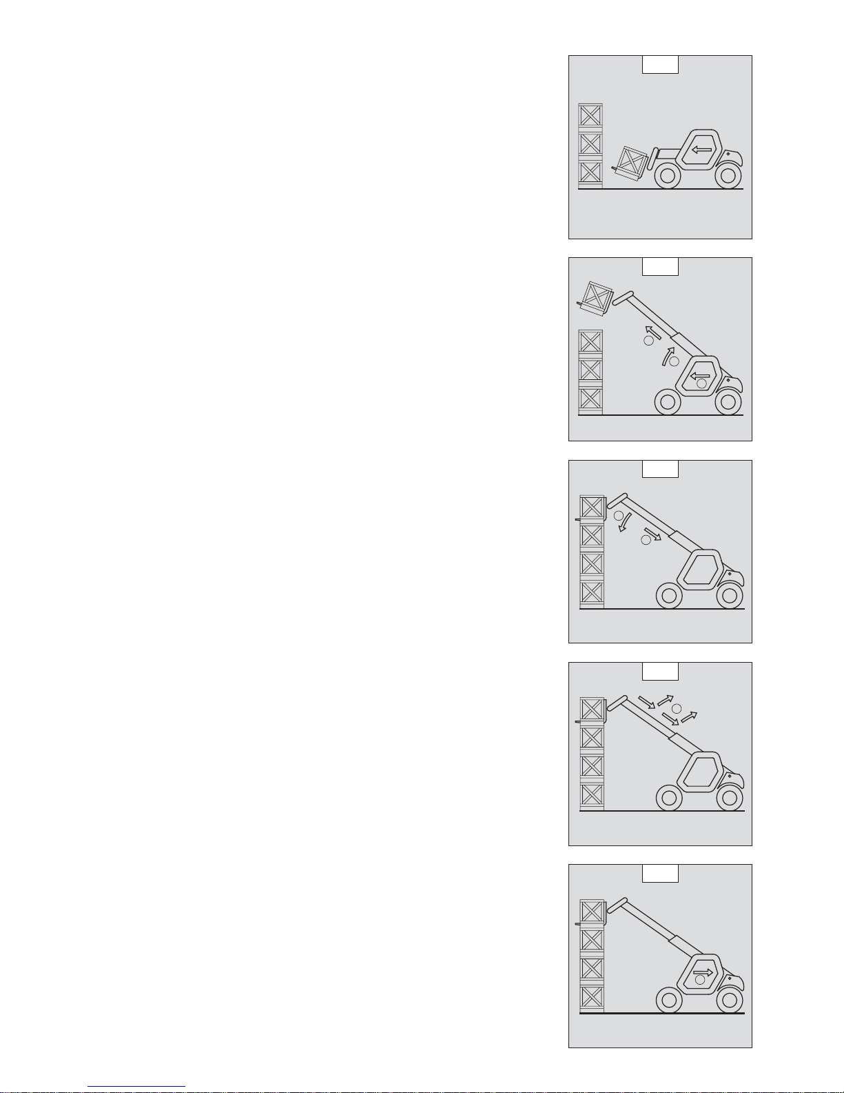
LAYING A HIGH LOAD ON TYRES
- Approach the load in the transport position in front of the pile (fig. F6).
- Put the handbrake on and set the forward/reverse selector to neutral.
- Lift and extend the jib (1) (2) until the load is above the pile, while keeping an eye on the
longitudinal stability limiter and warning device (see: INSTRUCTIONS FOR HANDLING A LOAD:
C - LONGITUDINAL STABILITY LIMITER AND WARNING DEVICE). If necessary, move the lift
truck (3) forward (fig. F7), driving very slowly and carefully.
- Place the load in a horizontal position and lay it down on the pile by lowering and retracting
the jib (1) (2) in order to position the load correctly (fig. F8).
- If possible, release the fork by alternately retracting and raising the jib (1) (fig. F9). Then set the
forks into transport position.
- If this is not possible, reverse the lift truck (1) very slowly and carefully to release the forks (fig.
F10). Then set them into transport position.
F6
1
2
3
F7
1
2
F8
1
F9
1
F10
Page 24

1-18
G - TAKING UP AND LAYING DOWN A SUSPENDED LOAD
WARNING: Failure to follow the above instructions may lead the lift truck to loose stability and overturn.
MUST be used with a lift truck equipped with an operational hydraulic movement cut-out device.
CONDITIONS OF USE
- The length of the sling or the chain shall be as short as possible to limit swinging of the load.
- Lift the load vertically along its axis, never by pulling sideways or lengthways.
HANDLING WITHOUT MOVING THE LIFT TRUCK
- Whether on stabilisers or on tyres, the lateral attitude must not exceed 1 % and the longitudinal attitude must not exceed 5%, the
bubble of the level must be held at “0”.
- Ensure that the wind speed is not higher than 10 m/s.
- Ensure that there is no one between the load and the lift truck.
H - TRAVELLING WITH A SUSPENDED LOAD
- Before moving, inspect the terrain in order to avoid excessive slopes and cross-falls, bumps and potholes, or soft ground.
- Ensure that the wind speed is not higher than 10 m/s.
- The lift truck must not travel at more than 0.4 m/s (1.5 km/h, i.e., one quarter walking speed).
- Drive and stop the lift truck gently and smoothly to minimise swinging of the load.
- Carry the load a few centimetres above the ground (max. 30 cm) the shortest possible jib length. Do not exceed the offset indicated on
the load chart. If the load begins to swing excessively, do not hesitate to stop and lower the jib to set down the load.
- Before moving the lift truck, check the longitudinal stability limiter and warning device (see: 2 - DESCRIPTION: INSTRUMENTS AND
CONTROLS), only the green LEDs and possibly the yellow LEDs should be lit.
- During transpor t, the lif t truck operator must be assisted by a person on the ground (standing a minimum of 3 m from the load), who
will limit swinging of the load using a bar or a rope. Ensure that this person is always clearly in view.
- The lateral attitude must not exceed 5%, the bubble in the level must be kept between the two “MAX.” marks
- The longitudinal attitude must not exceed 15%, with the load facing uphill, and 10%, with the load facing downhill.
- The jib angle must not exceed 45°.
- If the first red LED of the longitudinal stability limiter and warning device (see: 2 - DESCRIPTION: INSTRUMENTS AND CONTROLS) comes
on while travelling, gently bring the lift truck to a stop and stabilise the load. Retract the telescope to reduce the offset of the load.
Page 25

1-19
PLATFORM OPERATING INSTRUCTIONS
For PLATFORM-fitted lift trucks
Installation of the platform on the lift truck is only possible if the shields “operating the platform” of the lift truck and the platform are identical (see: 2 -
DESCRIPTION: OPERATING THE PLATFORM).
A - AUTHORISATION FOR USE
- Operation of the platform requires further authorisation in addition to that of the lift truck.
B - SUITABILITY OF THE TRUCK FOR USE
- MANITOU has ensured that this lift truck is suitable for use under the standard operating conditions defined in this operator’s manual,
with a STA TIC test coefficient of 1.25 and a DYNAMIC test coefficient of 1.1, as specified in harmonised standard EN 280 for “mobile
elevating work platforms”.
- Before commissioning, the company manager must make sure that the platform is appropriate for the work to be done, and perform
certain tests (in accordance with current legislation).
C - PRECAUTIONS WHEN USING THE PLATFORM
- Wear clothes suited for operating the platform, avoid loose clothes.
- Never operate the platform when hands or feet are wet or soiled with greasy substances.
- Always pay attention when using the platform. Do not listen to the radio or music using headphones or earphones.
- For increased comfort, adopt the correct position at the platform’s operator station.
- The platform’s guard rail exempts the operator from wearing a safety harness under normal operating conditions. As a result, you are
responsible deciding whether to wear a safety harness.
- The controls must not be used for any other than their intended purpose (e.g. getting in and out of the lift truck, coat hanger etc.).
- Safety helmets must be worn.
- The operator must always be in the normal operator’s position. It is prohibited to have arms or legs, or generally any part of the body,
protruding from the basket.
- Ensure that any materials loaded onto the platform (pipes, cables, containers, etc.) cannot fall out. Do not pile these materials to the
point where it is necessary to step over them.
D - USING THE PLATFORM
- However experienced the y ma y be, operators must acquaint themselv es with the emplacement and operation of all contr ol instruments
prior to operating the platform.
- Check before operating that the platform has been correctly assembled and locked onto the lift truck.
- Check before operating the platform that the access gate has been properly locked.
- The platform should be operated in an area free of any obstructions or danger when it is lowered to the ground.
- The operator using the platform must be aided on the ground by a person with adequate training.
- You should stay within the limits set out in the platform load chart.
- The lateral stresses are limited pressure (see: 2 - DESCRIPTION: CHARACTERISTICS).
- It is strictly forbidden to hand a load from the platform or the lift truck jib without a specially designed attachment (see: INSTRUCTIONS FOR
HANDLING A LOAD: H - TAKING UP AND LAYING DOWN A SUSPENDED LOAD).
- The platform cannot be used as a crane or a lift for permanently transporting people or materials, nor as jacks or supports.
- The lift truck must not be moved with one (or more) person(s) in the platform.
- It is forbidden to transport people on the platform using the hydraulic controls in the lift truck’s driver’s cab (except in case of rescue).
- The operator must not get in or out of the platform when it is not on ground level (jib retracted and in the down position).
- The platform must not be fitted with attachments that increase the unit’s wind load.
- Do not use ladders or improvised structures in the platform to gain extra height.
- Do not climb onto the sides of the platform to gain extra height.
E - ENVIRONMENT
Operating the platform close to electricity cables is forbidden. Maintain the specified
safe distances.
NOMINAL VOLTAGE
DISTANCE ABOVE THE
GROUND OR THE FLOOR
IN METRES
50 < U < 1000 2,30 M
1000 < U < 30000 2,50 M
30000 < U < 45000 2,60 M
45000 < U < 63000 2,80 M
63000 < U < 90000 3,00 M
90000 < U < 150000 3,40 M
150000 < U < 225000 4,00 M
225000 < U < 400000 5,30 M
400000 < U < 750000 7,90 M
Page 26

1-20
Operation of the platform is strictly forbidden in the event of wind speeds of over 45 km/h.
- The following scale is given for an empiric evaluation of the wind speed:
BEAUFORT scale (wind speed at a height of 10 m from flat ground)
Force Type of wind
Speed
(knots)
Speed
(kph)
Speed
(m/s)
Effects on Land Sea condition
0
Calm
0 - 1 0 - 1 < 0,3
Smoke rises vertically. Sea like a mirror.
1
Light air
1 - 3 1 - 5 0,3 - 1,5
The wind bends the smoke. Ripples but without foam crests.
2
Light breeze
4 - 6 6 - 11 1,6 - 3,3
The wind can be felt on the face,
shakes the leaves.
Small but evident wavelets.
3
Gentle
breeze
7 - 10 12 - 19 3,4 - 5,4
The wind continuously shakes the
leaves and twigs.
Large wavelets Perhaps scattered
white horses.
4
Moderate
breeze
11 - 16 20 - 28 5,5 - 7,9
The wind raises dust and scraps of
paper, shakes the twigs.
Small waves. Fairly frequent white
horses.
5
Fresh breeze
17 - 21 29 - 38 8 - 10,7
Leafy shrubs sway.
Small waves form on inland waters.
Moderate waves, many white horses.
6
Strong
breeze
22 - 27 39 - 49 10,8 - 13,8
Shakes thick branches, metal wires
hum, it becomes difficult to keep an
umbrella open.
Large waves begin to f orm, white f oam
crests, probably spray.
7
Near gale
28 - 33 50 - 61 13,9 - 17,1
Whole trees sway, it is difficult to walk
against the wind.
Sea heaps up and white foam blown
in streaks along the direction of the
wind.
8
Gale
34 - 40 62 - 74 17,2 - 20,7
Breaks the branches of trees, it is
almost impossible to walk against the
wind.
Moderately high waves, crests begin
to break into spindrift.
9
Strong gale
41 - 47 75 - 88 20,8 - 24,4
Causes slight damage to buildings
(stacks, tiles, etc..).
High waves. Dense foam along the
direction of the wind. Crests of waves
begin to roll over. Spray may affect
visibility.
10
Storm
48 - 55 89 - 102 24,5 - 28,4
Rare inland, uproots trees, causes
considerable damage to buildings.
Very high waves with long ov erhanging
crests. Visibility affected.
11
Violent storm
56 - 63 103 - 117 28,5 - 32,6
Very rare, causes extensive
devastation.
Exceptionally high waves that may
hide medium sized ships. Visibility
affected.
12
Hurricane
64 + 118 + 32,7 +
Causes very serious catastrophes.
The air is filled with foam and spray.
Sea completely white with driving
spray. Visibility very seriously affected.
F - MAINTENANCE
Your platform must be periodically inspected to ensure its continued compliance. The inspection frequency is defined by the current legislation in the country
in which the platform is used.
Page 27

1-21
INSTRUCTIONS FOR USING THE RADIO-CONTROL
For lift trucks with RC radio control
HOW TO USE THE RADIO-CONTROL
SAFETY INSTRUCTIONS
- This radio-contr ol consists of electronic and mechanical safety elements. It cannot receiv e commands from another transmitte r because
the internal encoding is unique to each radio-control.
If it is used improperly or incorrectly, there is a risk of danger to:
- The physical and mental health of the user or others.
- The lift truck and other neighbouring items.
Everyone working with this radio-control:
- Must be qualified in line with current regulations and therefore appropriately trained.
- Must follow this instruction manual as closely as possible.
- The system is used to control the lift truck remotely via radio waves. Commands are also transmitted if the lift truck is out of sight
(behind an obstacle or a building for example), this is why:
• After stopping the truck and removing the key button (only possible when it is stationary), always place the transmitter in a
safe, dry place.
• Before performing any installation, servicing or repair work, always switch off power sources (in particular, electric welding
devices and electric head units on hydraulic distributors must be disconnected at each section).
• Never remove or alter the safety devices (such as the hand-guard frame, key, emergency stop button, etc.).
Never drive the lift truck if it is not continuously and perfectly within view of the operator!
- Before leaving the transmitter, the operator must mak e sure that it cannot be used b y an unauthorized thir d person: either b y remo ving
the key button from the transmitter or locking it in an inaccessible place.
- The user must ensure that the instruction manual is accessible at all times and that operators have read and understood it.
INSTRUCTIONS
- Take up position in a stable place with no risk of slipping.
- Before using the transmitter, make sure there is nobody within the working area.
- Only use the transmitter with its carrying device or installed correctly on the platform.
When you remove the transmitter, remove the accumulator and key button so that it cannot be used accidentally or deliberately by anyone else.
PROTECTIVE DEVICES
- The lift truck will be immobilised within 450 milliseconds (approx. 0.5 second) at most:
• If the transmitter emergency stop button (50 milliseconds), or the one on the lift is pressed.
• If the transmission distance of the radio waves is exceeded.
• If the transmitter is faulty.
• If an interfering radio signal is received from elsewhere.
• If the accumulator is removed from its housing in the transmitter.
• If the accumulator reaches the end of its autonomy.
• If the transmitter is switched off by turning the key button to stop.
- These protective devices are provided for the safety of personnel and property and must never be altered, removed or bypassed in any
way whatsoever!
- The hand-guard frame prevents external action on a manipulator (if the transmitter falls, for example, or if the operator leans on a
guard-rail).
- An electronic safety device prevents radio transmission from being initiat ed if the manipulat ors are not mechanically and electrically at
rest and if the internal combustion engine speed selector is not set to idle.
In an emergency, press the transmitter emergency stop button immediately ; then follow the manual’s instructions (see: 2 - DESCRIPTION: INSTRUMENTS AND
CONTROLS).
Page 28

1-22
MAINTENANCE INSTRUCTIONS OF THE LIFT TRUCK
GENERAL INSTRUCTIONS
- Ensure the area is sufficiently ventilated before starting the lift truck.
- Wear clothes suitable for the maintenance of the lift truck, avoid wearing jewellery and loose clothes. Tie and protect your hair, if
necessary.
- Stop the I.C. engine and remove the ignition key, when an intervention is necessary.
- Read the operator’s manual carefully.
- Carry out all repairs immediately, even if the repairs concerned are minor.
- Repair all leaks immediately, even if the leak concerned is minor.
- Make sure that the disposal of process materials and of spare parts is carried out in total safety and in a ecological way.
- Be careful of the risk of burning and splashing (exhaust, radiator, I.C. engine, etc.).
MAINTENANCE
- Perform the periodic service (see: 3 - MAINTENANCE) to keep your lift truck in good working conditions. Failure to perform the periodic
service may cancel the contractual guarantee.
MAINTENANCE LOGBOOK
- The maintenance operations carried out in accordance with the recommendations given in part: 3 - MAINTENANCE and the other
inspection, servicing or repair operations or modifications performed on the lift truck or its attachments shall be recorded in a
maintenance logbook. The entry for each operation shall include details of the date of the works, the names of the individuals or
companies having performed them, the type of operation and its frequency, if applicable. The part numbers of any lift truck items
replaced shall also be indicated.
LUBRICANT AND FUEL LEVELS
- Use the recommended lubricants (never use contaminated lubricants).
- Do not fill the fuel tank when the I.C. engine is running.
- Only fill up the fuel tank in areas specified for this purpose.
- Do not fill the fuel tank to the maximum level.
- Do not smoke or approach the lift truck with a flame, when the fuel tank is open or is being filled.
HYDRAULIC
- Any work on the load handling hydraulic circuit is forbidden except for the operations described in part: 3 - MAINTENANCE.
- Do not attempt to loosen unions, hoses or any hydraulic component with the circuit under pressure.
BALANCING VALVE: It is dangerous to change the setting and remove the balancing valv es or safety valves which may be fitted to your lift truck cylinders. These
operations must only be performed by approved personnel (consult your dealer).
The HYDRAULIC ACCUMULATORS that may be fitted on your lift truck are pressurized units. Removing these accumulators and their pipework is a dangerous
operation and must only be performed by approved personnel (consult your dealer).
ELECTRICITY
- Do not short-circuit the starter relay to start the IC engine. If the forward/reverse selector is not in neutral and the parking brake is not
engaged, the lift truck may suddenly start to move.
- Do not drop metallic items on the battery.
- Disconnect the battery before working on the electrical circuit.
Page 29

1-23
WELDING
- Disconnect the battery before any welding operations on the lift truck.
- When carrying out electric welding work on the lift truck, connect the negative cable from the equipment directly to the part being
welded, so as to avoid high tension current passing through the alternator.
- Never carry out welding or work which gives off heat on an assembled tyre. The heat would increase the pressure which could cause
the tyre to explode.
- If the lift truck is equipped with an electronic control unit, disconnect this before starting to weld, to av oid the risk of causing irreparable
damage to electronic components.
WASHING THE LIFT TRUCK
- Clean the lift truck or at least the area concerned before any intervention.
- Remember to close and lock all accesses to the lift truck (doors, windows, cowls…).
- During washing, avoid the articulations and electrical components and connections.
- If necessary, protect against penetration of water, steam or cleaning agents, components susceptible of being damaged, particularly
electrical components and connections and the injection pump.
- Clean the lift truck of any fuel, oil or grease trace.
FOR ANY INTERVENTION OTHER THAN REGULAR MAINTENANCE, CONSULT YOUR DEALER.
Page 30

1-24
IF THE LIFT TRUCK IS NOT TO BE USED FOR A LONG TIME
INTRODUCTION
The following recommendations are intended to prevent the lift truck from being damaged when it is withdrawn from service for an
extended period.
For these operations, we recommend the use of a MANITOU protective product, reference 603726.
Instructions for using the product are given on the packaging.
Procedures to follow if the lift truck is not to be used for a long time and for starting it up again afterwards must be performed by your dealership.
PREPARING THE LIFT TRUCK
- Clean the lift truck thoroughly.
- Check and repair any leakage of fuel, oil, water or air.
- Replace or repair any worn or damaged parts.
- Wash the painted surfaces of the lift truck in clear and cold water and wipe them.
- Touch up the paintwork if necessary.
- Shut down the lift truck (see: OPERATING INSTRUCTIONS UNLADEN AND LADEN).
- Make sure the jib cylinder rods are all in retracted position.
- Release the pressure in the hydraulic circuits.
PROTECTING THE I.C. ENGINE
- Fill the tank with fuel (see: 3 - MAINTENANCE: A - DAILY OR EVERY 10 HOURS SERVICE).
- Empty and replace the cooling liquid (see: 3 - MAINTENANCE: F - EVERY 2000 HOURS SERVICE).
- Leave the I.C. engine running at idling speed for a few minutes, then switch off.
- Replace the I.C. engine oil and oil filter (see: 3 - MAINTENANCE: D - EVERY 500 HOURS SERVICE).
- Add the protective product to the engine oil.
- Run the I.C. engine for a short time so that the oil and cooling liquid circulate inside.
- Disconnect the battery and store it in a safe place away from the cold, after charging it to a maximum.
- Remove the injectors and spray the protective product into each cylinder for two seconds with the piston in low neutral position.
- Turn the crankshaft once slowly and refit the injectors (see I.C. engine REPAIR MANUAL).
- Remove the intake hose from the manifold or turbocharger and spray the protective product into the manifold or turbocharger.
- Cap the intake manifold or turbocharger hole with waterproof adhesive tape.
- Remove the exhaust pipe and spray the protective product into the exhaust manifold or turbocharger.
- Refit the exhaust pipe and block the outlet with waterproof adhesive tape.
NOTE: The spray time is noted on the product packaging and must be increased by 50 % for turbo engines.
- Open the filler plug, spray the protective product around the rocker arm shaft and refit the filler plug.
- Cap the fuel tank using waterproof adhesive tape.
- Remove the drive belts and store them in a safe place.
- Disconnect the engine cut-off solenoid on the injection pump and carefully insulate the connection.
PROTECTING THE LIFT TRUCK
- Set the lift truck on axle stands so that the tyres are not in contact with the ground and release the handbrake.
- Protect cylinder rods which will not be retracted, from corrosion.
- Wrap the tyres.
NOTE: If the lift truck is to be stored outdoors, cover it with a waterproof tarpaulin.
Page 31

1-25
BRINGING THE LIFT TRUCK BACK INTO SERVICE
- Remove the waterproof adhesive tape from all the holes.
- Refit the intake hose.
- Refit and reconnect the battery.
- Remove the protection from the cylinder rods.
- Perform the daily service (see: 3 - MAINTENANCE: A - DAILY OR EVERY 10 HOURS SERVICE).
- Put the handbrake on and remove the axle stands.
- Empty and replace the fuel and replace the fuel filter (see: 3 - MAINTENANCE: D - EVERY 500 HOURS SERVICE).
- Refit and set the tension in the drive belts (see: 3 - MAINTENANCE: C - EVERY 250 HOURS SERVICE).
- Turn the I.C. engine using the starter, to allow the oil pressure to rise.
- Reconnect the engine cut-off solenoid.
- Lubricate the lift truck completely (see: 3 - MAINTENANCE: SERVICING SCHEDULE).
Make sure the area is adequately ventilated before starting up the lift truck.
- Start up the lift truck, following the safety instructions and regulations (see: OPERATING INSTRUCTIONS UNLADEN AND LADEN).
- Run all the jib’s hydraulic movements, concentrating on the ends of travel for each cylinder.
Page 32

1-26
Page 33

2-1
2 - DESCRIPTION
Page 34

2-2
Page 35

2-3
TABLE OF CONTENTS
« EC» DECLARATION OF CONFORMITY
2-4
IDENTIFICATION OF THE LIFT TRUCK
2-6
CHARACTERISTICS
2-7
DIMENSIONS AND LOAD CHART
2-21
INSTRUMENTS AND CONTROLS
2-23
TOWING PIN AND HOOK
2-72
DESCRIPTION AND USE OF THE OPTIONS
2-76
Page 36

2-4
« EC» DECLARATION OF CONFORMITY
1) DECLARATION "CE" DE CONFORMITE (originale)
"
EECC""DDEECCLLAARRAATTIIOONNOOFFCCOONNFFOORRMMIITTY
Y
((oorriiggiinnaall)
)
2) La société, The company : MANITOU C.I.
3) Adresse, Address : Via Cristoforo Colombo 2, 41013 Cavazzona in Castelfranco Emilia –ITALIE
4)Dossier technique,Technical fi le : Manitou C.I., Via Cristoforo Colombo 2, 41013 Cavazzona in
Castelfranco Emilia (MO) , Italie
5) Constructeur de la machine décrite ci-après, Manufacturer of the machine described below :
CHARIOT ELEVATEUR MHT ... T N° 3
PFB p.n............ + FOURCHES ...... KG p.n.........
6) Déclare que cette machine, Declares that this machine :
7)- Est conforme aux directives suivantes et à leurs transpositions en droit national, Complies
with the following directives and their transpositions into national law
:
8) - Pour les machines annexe IV , For annex IV machines :
9) - Numéro d’attestation, Certifi cate number: /
10) - Organisme notifi é, Notifi ed body : /
11) -Procédure appliquée, Applied procedure : Annexe VI – 2000 / 14 / CE proc.I
10) - Organisme notifi é, Notifi ed body : ECO s.p.a. EUROPEAN CERTIFYNG .........................
ORGANIZATION,
Via Mengolina 33 48018 Faenza- Ravenna - Italia –
Organismo notifi cato n° 0714
12) - Niveau de puissance acoustique, Sound power level :
13) Mesuré, Measured : 106 dB (A)
14) Garanti,
Guaranteed : 108 dB (A)
15)-Normes harmonisées utilisées, Harmonised standards used : EN 12895
16)-Normes ou dispositions techniques utilisées, Standards or technical provisions used :
EN 1459 : 1999 + A1 : 2007
17) - Fait à, Done at : CASTELFRANCO EMILIA 18) - Date, Date : / /
19) - Nom du signataire, Name of signatory : FELICANI DANIELE
20) - Fonction, Function : DIRECTEUR TECHNIQUE
21) - Signature, Signature :
Page 37

2-5
bg : 1) удостоверение за « СЕ » съответствие (oригинална), 2) Фирмата, 3) Адрес, 4) Техническо досие, 5) Фабрикант на описаната по-долу машина, 6) Обявява, че
тази машина, 7) Отговаря на следните директиви и на тяхното съответствие национално право, 8) За машините към допълнение IV, 9)Номер на удостоверението, 10)
Наименувана фирма, 15) хармонизирани стандарти използвани, 16) стандарти или технически правила, използвани, 17) Изработено в, 18) Дата, 19) Име на разписалия
се, 20) Функция, 21) Функция.
cs : 1)
ES prohlášení o shodě (původní), 2) Název společnosti, 3) Adresa, 4) Technická dokumentace, 5) Výrobce níže uvedeného stroje, 6) Prohlašuje, že tento stroj,
7) Je v souladu s následujícími směrnicemi a směrnicemi transponovanými do vnitrostátního práva, 8) Pro stroje v příloze IV, 9) Číslo certifikátu, 10) Notifikační orgán,
15) harmonizované normy použity, 16) Norem a technických pravidel používaných, 17) Místo vydání, 18) Datum vydání, 19) Jméno podepsaného, 20) Funkce, 21) Podpis.
da : 1)
EF Overensstemmelseserklæring (original), 2) Firmaet, 3) Adresse, 4) tekniske dossier, 5) Konstruktør af nedenfor beskrevne maskine, 6) Erklærer, at denne maskine,
7) Overholder nedennævnte direktiver og disses gennemførelse til national ret, 8) For maskiner under bilag IV, 9) Certifikat nummer, 10) Bemyndigede organ, 15) harmoniserede
standarder, der anvendes, 16) standarder eller tekniske regler, 17) Udfærdiget i, 18) Dato, 19) Underskrivers navn, 20) Funktion, 21) Underskrift.
de : 1) EG-Konformitätserklärung (original), 2) Die Firma, 3) Adresse, 4) Technischen Unterlagen, 5) Hersteller der nachfolgend beschriebenen Maschine, 6) Erklärt, dass diese
Maschine, 7) den folgenden Richtlinien und deren Umsetzung in die nationale Gesetzgebung entspricht, 8) Für die Maschinen laut Anhang IV, 9) Bescheinigungsnummer,
10) Benannte Stelle, 15) angewandten harmonisierten Normen, 16) angewandten sonstigen technischen Normen und Spezifikationen, 17) Ausgestellt in, 18) Datum,
19) Name des Unterzeichners, 20) Funktion, 21) Unterschrift.
el : 1) Δήλωση συμμόρφωσης CE (πρωτότυπο), 2) Η εταιρεία, 3) Διεύθυνση, 4) τεχνικό φάκελο, 5) Κατασκευάστρια του εξής περιγραφόμενου μηχανήματος,
6) Δηλώνει ότι αυτό το μηχάνημα, 7) Είναι σύμφωνο με τις εξής οδηγίες και τις προσαρμογές τους στο εθνικό δίκαιο, 8) Για τα μηχανήματα παραρτήματος IV,
9) Αριθμός δήλωσης, 10) Κοινοποιημένος φορέας, 15) εναρμονισμένα πρότυπα που χρησιμοποιούνται, 16) Πρότυπα ή τεχνικούς κανόνες που χρησιμοποιούνται,
16) Είναι σύμφωνο με τα εξής πρότυπα και τεχνικές διατάξεις, 17) Εν, 18) Ημερομηνία, 19) Όνομα του υπογράφοντος, 20) Θέση, 21) Υπογραφή.
es : 1)Declaración DE de conformidad (original), 2) La sociedad, 3) Dirección, 4) expediente técnico, 5) Constructor de la máquina descrita a continuación, 6) Declara que esta
máquina, 7) Está conforme a las siguientes directivas y a sus transposiciones en derecho nacional, 8) Para las máquinas anexo IV, 9) Número de certificación, 10) Organismo
notificado, 15) normas armonizadas utilizadas, 16) Otras normas o especificaciones técnicas utilizadas, 17) Hecho en, 18) Fecha, 19) Nombre del signatario, 20) Función, 21) Firma.
et : 1) EÜ vastavusdeklaratsioon (algupärane), 2) Äriühing, 3) Aadress, 4) Tehniline dokumentatsioon, 5) Seadme tootja, 6) Kinnitab, et see toode, 7) On vastavuses järgmiste
direktiivide ja nende riigisisesesse õigusesse ülevõtmiseks vastuvõetud õigusaktidega, 8) IV lisas loetletud seadmete puhul, 9) Tunnistuse number, 10) Sertifitseerimisasutus,
15) kasutatud ühtlustatud standarditele, 16) Muud standardites või spetsifikatsioonides kasutatakse, 17) Väljaandmise koht, 18) Väljaandmise aeg, 19) Allkirjastaja nimi,
20) Amet, 21) Allkiri.
fi : 1) EY-vaatimustenmukaisuusvakuutus (alkuperäiset), 2) Yritys, 3) Osoite, 4) teknisen eritelmän, 5) Jäljessä kuvatun koneen valmistaja, 6) Vakuuttaa, että tämä kone,
7) Täyttää seuraavien direktiivien sekä niitä vastaavien kansallisten säännösten vaatimukset, 8) Liitteen IV koneiden osalta, 9) Todistuksen numero, 10) Ilmoitettu laitos,
15) yhdenmukaistettuja standardeja käytetään, 16) muita standardeja tai, 17) Paikka, 18) Aika, 19) Allekirjoittajan nimi, 20) Toimi, 21) Allekirjoitus.
ga : 1) « EC »dearbhú comhréireachta (bunaidh), 2) An comhlacht, 3) Seoladh, 4) comhad teicniúil, 5) Déantóir an innill a thuairiscítear thíos, 6) Dearbhaíonn sé go bhfuil an t-inneall,
7) Go gcloíonn sé le na treoracha seo a leanas agus a trasuímh isteach i ndlí náisiúnta, 8) Le haghaidh innill an aguisín IV, 9) Uimhir teastais, 10) Comhlacht a chuireadh i bhfios,
15) caighdeáin comhchuibhithe a úsáidtear, 16) caighdeáin eile nó sonraíochtaí teicniúla a úsáidtear, 17) Déanta ag, 18) Dáta, 19) Ainm an tsínitheora, 20) Feidhm, 21) Síniú.
hu : 1) CE megfelelőségi nyilatkozat (eredeti), 2) A vállalat, 3) Cím, 4) műszaki dokumentáció, 5) Az alábbi gép gyártója, 6) Kijelenti, hogy a gép, 7) Megfelel az alábbi
irányelveknek valamint azok honosított előírásainak, 8) A IV. melléklet gépeihez, 9) Bizonylati szám, 10) Értesített szervezet, 15) felhasznált harmonizált szabványok,
16) egyéb felhasznált műszaki szabványok és előírások hivatkozásai, 17) Kelt (hely), 18) Dátum, 19) Aláíró neve, 20) Funkció, 21) Aláírás.
is : 1) (Samræmisvottorð ESB (upprunalega), 2) Fyrirtækið, 3) Aðsetur, 4) Tæknilegar skrá, 5) Smiður tækisins sem lýst er hér á eftir, 6) Staðfestir að tækið, 7) Samræmist
eftirfarandi stöðlum og staðfærslu þeirra með hliðsjón af þjóðarrétti, 8) Fyrir tækin í aukakafla IV, 9) Staðfestingarnúmer, 10) Tilkynnt til, 15) samhæfða staðla sem notaðir,
16) önnur staðlar eða forskriftir notað, 17) Staður, 18) Dagsetning, 19) Nafn undirritaðs, 20) Staða, 21) Undirskrift.
it : 1) Dichiarazione CE di conformità (originale), 2) La società, 3) Indirizzo, 4) fascicolo tecnico, 5) Costruttore della macchina descritta di seguito, 6) Dichiara che questa
macchina, 7) È conforme alle direttive seguenti e alle relative trasposizioni nel diritto nazionale, 8) Per le macchine Allegato IV, 9) Numero di Attestazione, 10) Organismo
notificato, 15) norme armonizzate applicate, 16) altre norme e specifiche tecniche applicate, 17) Stabilita a, 18) Data, 19) Nome del firmatario, 20) Funzione, 21) Firma.
lt : 1) CE atitikties deklaracija (originalas), 2) Bendrovė, 3) Adresas, 4) Techninė byla, 5) Žemiau nurodytas įrenginio gamintojas, 6) Pareiškia, kad šis įrenginys, 7) Atitinka toliau
nurodytas direktyvas ir į nacionalinius teisės aktus perkeltas jų nuostatas, 8) IV priedas dėl mašinų, 9) Sertifikato Nr, 10) Paskelbtoji įstaiga, 15) suderintus standartus naudojamus,
16) Kiti standartai ir technines specifikacijas, 17) Pasirašyta, 18) Data, 19) Pasirašiusio asmens vardas ir pavardė, 20) Pareigos, 21) Parašas.
lv : 1) EK atbilstības deklarācija (oriģināls), 2) Uzņēmums, 3) Adrese, 4) tehniskās lietas, 5) Tālāk aprakstītās iekārtas ražotājs, 6) Apliecina, ka šī iekārta, 7) Ir atbilstoša tālāk
norādītajām direktīvām un to transpozīcijai nacionālajā likumdošanā, 8) Iekārtām IV pielikumā, 9) Apliecības numurs, 10) Reģistrētā organizācija, 15) lietotajiem saskaņotajiem
standartiem, 16) lietotajiem tehniskajiem standartiem un specifikācijām, 17) Sastādīts, 18) Datums, 19) Parakstītāja vārds, 20) Amats, 21) Paraksts.
mt : 1) Dikjarazzjoni ta’ Konformità KE (oriġinali), 2) Il-kumpanija, 3) Indirizz, 4) fajl tekniku, 5) Manifattriċi tal-magna deskritta hawn isfel, 6) Tiddikjara li din il-magna,
7) Hija konformi hija konformi mad-Direttivi segwenti u l-liġijiet li jimplimentawhom fil-liġi nazzjonali, 8) Għall-magni fl-Anness IV, 9) Numru taċ-ċertifikat, 10) Entità nnotifikata,
15) l-istandards armonizzati użati, 16) standards tekniċi u speċifikazzjonijiet oħra użati, 17) Magħmul f’, 18) Data, 19) Isem il-firmatarju, 20) Kariga, 21) Firma.
nl : 1) EG-verklaring van overeenstemming (oorspronkelijke), 2) Het bedrijf, 3) Adres, 4) technisch dossier, 5) Constructeur van de hierna genoemde machine, 6) Verklaart
dat deze machine, 7) In overeenstemming is met de volgende richtlijnen en hun omzettingen in het nationale recht, 8) Voor machines van bijlage IV, 9) Goedkeuringsnummer,
10) Aangezegde instelling, 15) gehanteerde geharmoniseerde normen, 16) andere gehanteerde technische normen en specificaties, 17) Opgemaakt te, 18) Datum,
19) Naam van ondergetekende, 20) Functie, 21) Handtekening.
no : 1) CE-samsvarserklæring (original), 2) Selskapet, 3) Adresse, 4) tekniske arkiv, 5) Fabrikant av følgende maskin, 6) Erklærer at denne maskinen, 7) Oppfyller kravene i
følgende direktiver, med nasjonale gjennomføringsbestemmelser, 8) For maskinene i tillegg IV, 9) Attestnummer, 10) Notifisert organ, 15) harmoniserte standarder som brukes,
16) Andre standarder og spesifikasjoner brukt, 17) Utstedt i, 18) Dato, 19) Underskriverens navn, 20) Stilling, 21) Underskrift.
pl : 1) Deklaracja zgodności CE (oryginalne), 2) Spółka, 3) Adres, 4) dokumentacji technicznej, 5) Wykonawca maszyny opisanej poniżej, 6) Oświadcza, że ta maszyna,
7) Jest zgodna z następującymi dyrektywami i odpowiadającymi przepisami prawa krajowego, 8) Dla maszyn załącznik IV, 9) Numer certyfikatu, 10) Jednostka certyfikująca,
15) zastosowanych norm zharmonizowanych, 16) innych zastosowanych norm technicznych i specyfikacji, 17) Sporządzono w, 18) Data, 19) Nazwisko podpisującego,
20) Stanowisko, 21) Podpis.
pt : 1) Declaração de conformidade CE (original), 2) A empresa, 3) Morada, 4) processo técnico, 5) Fabricante da máquina descrita abaixo, 6) Declara que esta máquina,
7) Está em conformidade às directivas seguintes e às suas transposições para o direito nacional, 8) Para as máquinas no anexo IV, 9) Número de certificado,
10) Entidade notificada, 15) normas harmonizadas utilizadas, 16) outras normas e especificações técnicas utilizadas, 17) Elaborado em, 18) Data, 19) Nome do signatário,
20) Cargo, 21) Assinatura.
ro : 1) Declaraţie de conformitate CE (originală), 2) Societatea, 3) Adresa, 4) cărtii tehnice, 5) Constructor al maşinii descrise mai jos, 6) Declară că prezenta maşină,
7) Este conformă cu directivele următoare şi cu transpunerea lor în dreptul naţional, 8) Pentru maşinile din anexa IV, 9) Număr de atestare, 10) Organism notificat, 15) standardele
armonizate utilizate, 16) alte standarde si specificatii tehnice utilizate, 17) Întocmit la, 18) Data, 19) Numele persoanei care semnează, 20) Funcţia, 21) Semnătura.
sk : 1) ES vyhlásenie o zhode (pôvodný), 2) Názov spoločnosti, 3) Adresa, 4) technickej dokumentácie, 5) Výrobca nižšie opísaného stroja, 6) Vyhlasuje, že tento stroj,
7) Je v súlade s nasledujúcimi smernicami a smernicami transponovanými do vnútroštátneho práva, 8) Pre stroje v prílohe IV, 9) Číslo certifikátu, 10) Notifikačný orgán,
15) použité harmonizované normy, 16) použité iné technické normy a predpisy, 17) Miesto vydania, 18) Dátum vydania, 19) Meno podpisujúceho, 20) Funkcia, 21) Podpis.
sl : 1) ES Izjava o ustreznosti (izvirna), 2) Družba. 3) Naslov. 4) tehnične dokumentacije, 5) Proizvajalac tukaj opisanega stroja, 6) Izjavlja, da je ta stroj, 7) Ustreza
naslednjim direktivam in njihovi transpoziciji v državno pravo, 8) Za stroje priloga IV, 9) Številka potrdila, 10) Obvestilo organu, 15) uporabljene harmonizirane standarde,
16) druge uporabljene tehnične standarde in zahteve, 17) V, 18) Datum, 19) Ime podpisnika, 20) Funkcija, 21) Podpis.
sv : 1)
CE-försäkran om överensstämmelse (original), 2) Företaget, 3) Adress, 4) tekniska dokumentationen, 5) Konstruktör av nedan beskrivna maskin, 6) Försäkrar att denna
maskin, 7) Överensstämmer med nedanstående direktiv och införlivandet av dem i nationell rätt, 8) För maskinerna i bilaga IV, 9) Nummer för godkännande, 10) Organism som
underrättats, 15) Harmoniserade standarder som använts, 16) andra tekniska standarder och specifikationer som använts, 17) Upprättat i, 18) Datum, 19) Namn på den som
undertecknat, 20) Befattning, 21) Namntecknin.
Page 38
2-6
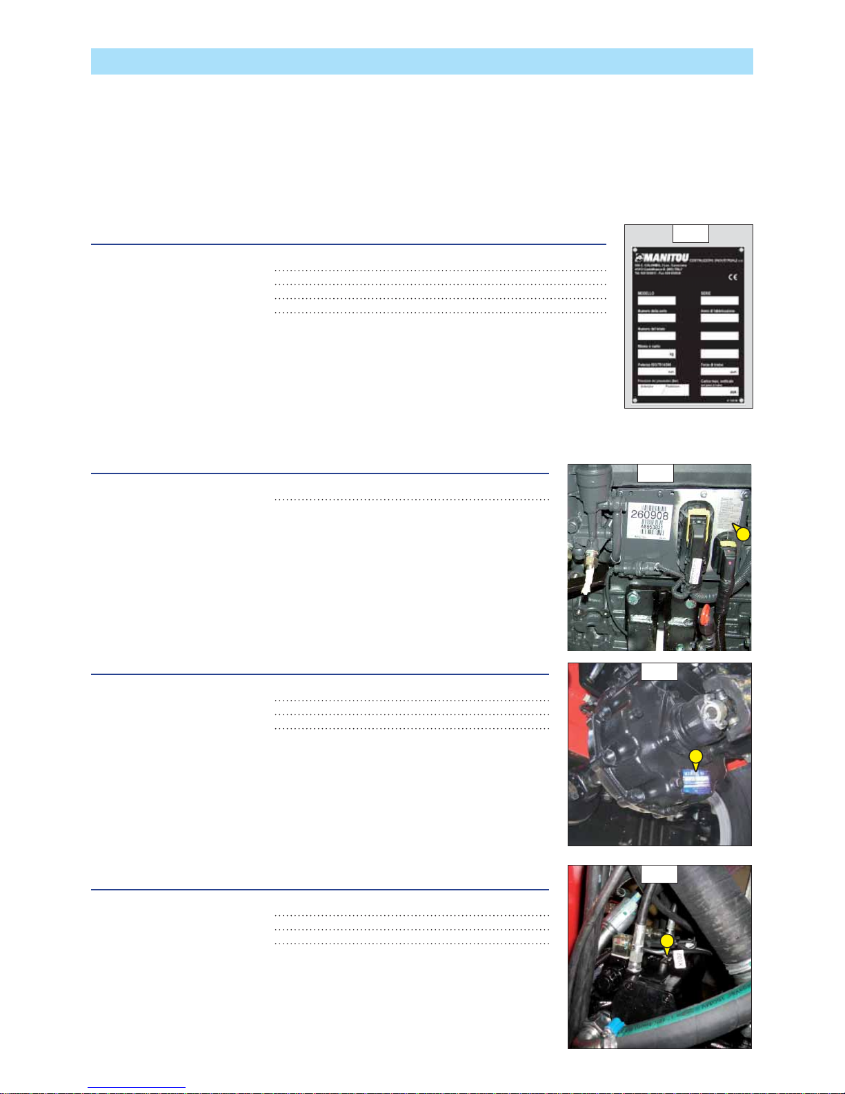
IDENTIFICATION OF THE LIFT TRUCK
As our policy is to promote a constant improvement of our products, our range of telescopic lift trucks may undergo certain modifications,
without obligation for us to advise our customers.
When you order parts, or when you require any technical information, always specify:
NOTE: For the owner’s convenience, it is recommended that a note of these numbers is made in the spaces provided, at the time of the
delivery of the lift truck.
LIFT TRUCK MANUFACTURER’S PLATE (FIG. A)
- Model
- Series
- Serial Nr
- Year of manufacture
For any further technical information regarding your lift truck refer to chapter: 2 - DESCRIPTION:
CHARACTERISTICS.
I.C. ENGINE (FIG. B)
- I.C. engine Nr
GEAR BOX (FIG. C)
- Type
- Serial Nr
- MANITOU reference
HYDROSTATIC PUMP (FIG. D)
- Type
- MANITOU reference
- Serial Nr
A
B
D
B
C
Page 39
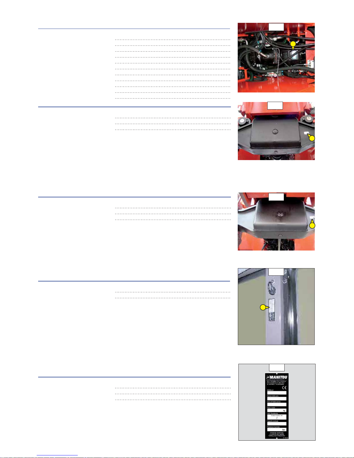
2-7
HYDROSTATIC MOTOR (FIG. E)
- Type
- MANITOU reference
- Serial Nr
FRONT AXLE (FIG. F)
- Type
- Serial Nr
- MANITOU reference
REAR AXLE (FIG. G)
- Type
- Serial Nr
- MANITOU reference
CAB (FIG. H)
- Type
- Serial Nr
PLATE MANUFACTURER OF THE ATTACHMENT (FIG. I)
- Model
- Serial Nr
- Year of manufacture
I
G
F
E
H
Page 40

2-8
CHARACTERISTICS
MHT 7140 T-E3
I.C. ENGINE
Type MERCEDES-BENZ (OM 904 LA)
Fuel Diesel
Number of cylinders 4 in line
Suction Supercharged
Injection system Direct
Ignition sequence 1,3,4,2
Capacity cm3 4250
Bore and stroke mm 102 x 130
Compression ratio 18:1
Nominal rating loaded rpm 2200
Rating slow unladen rpm 800
Max. rating unladen rpm 2400
Power ISO/TR 14396 cv- kW 175 - 129
Power SAE J 1995 cv- kW 175 - 129
Maximum torque ISO/TR 14396 Nm 675 Nm from 1200 to 1600 rpm
Air cleaner μm3
Type of cooling By water
Fan Puller
TRANSMISSION
Gear box DANA
Type
Meccanic, with differential block and hydraulic
control
Forward/reverse selector Electromagnetic
Number of forward speeds 2
Number of reverse speeds 2
Hydrostatic pump REXROTH
Type
A4VG125DA Hydrostatic with continuous
speed adjustment and engine with inching
Main pump
displacement min./max. cm
3
/giri 0 a 125
Capacity max. L/min. 285
Pressure bar 465
Supply pump
displacement cm
3
28,3
Capacity max. L/min. 65
Pressure bar 32 ±2
Hydrostatic motor REXROTH
Type A6VM160DA
displacement min./max. cm
3
/giri 75 a 160
Front axle OMCI Heavy duty
Differential NO Limited slip
Reduction gear Planetary gear
Rear axle OMCI Heavy duty
Reduction gear Planetary gear
Drive wheels 4RM Permanent
Front tyres MICHELIN
Size 16.00 (445/95) R25 XLB 177E
Pressure bar 9
Rear tyres MICHELIN
Size 16.00 (445/95) R25 XLB 177E
Pressure bar 9
ELECTRIC CIRCUIT
Battery Standard 12 V - 120 Ah - 850 A EN
Alternator 14 V - 90 ÷ 150 A
Starter 12 V - 3,2 kW
BRAKE CIRCUIT
Service brake Hydraulic power brake
Type of brake Multidisk brake immersed in oil
Type of control Foot-operated for the front and rear axles
Parking brake
Type of brake
Negative action, acts on front and rear axle
service brakes
Type of control Electro-hydrailc
Page 41

2-9
SPECIFICATIONS AND WEIGHTS
Speed of movement for lift truck in standard configuration on flat
ground (except particular conditions)
Front unladen km/h
25
laden km/h 8
Rear unladen km/h 25
laden km/h 8
Rated capacity with standard attachment kg 14000
Standard lifting height kg 7000
Standard attachment forks PFB
Fork dimensions (length x width x thickness) mm 1500 x 200 x 80
Distance from the centre of gravity from the load to the lug of the forks
mm 600
Weight with standard attachment
Unladen kg 20570
At rated load kg 34570
Weight per axle with standard attachment (transport position)
Front unladen kg
8430
Rear unladen kg 12140
Drag strain on the coupling hook
Unladen (sliding) daN
-
At rated load (transmission setting) daN 15500
Pull strain with open carrier
(according to standard ISO 8313)
daN -
HYDRAULIC MOVEMENTS
Longitudinal stability limiter and warning device Electronic
Lifting motions (boom retracted)
Unladen lifting s - m/mn
-
Unladen lowering s - m/mn -
Telescoping motions (boom raised)
Unladen extending s - m/mn
-
Unladen retracting s - m/mn -
Tilting movements
Unladen digging s - °/s
-
Forward tilting unladen s - °/s -
HYDRAULIC CIRCUIT
Hydraulic pump
Type Gear pump
1st casing
Capacity cm3 75
Max. rating capacity unladen l/mn 170
Flow rate at 1600 rpm l/mn 120
Maximum service pressure bar
350
Telescoping circuit bar 290 / 350
Lifting circuit bar 320 / 320
Tilt circuit bar 200 / 350
Attachment circuit bar 270
Steering circuit bar 200
SOUND AND VIBRATION
Level of sound pressure in the driver’s cab LpA
(according to standard NF EN 12053)
dB 79,2
Level of sound power ensured in the LwA environment
(according to directive 2000/14/EC modified by directive 2005/88/EC)
dB
106 (measured)
108 (ensured)
Average weighted acceleration on driver’s body
(according to standard NF EN 13059)
m/s2
The average weighted acceleration transmitted to the driver’s hand/arm system
(according to standard ISO 5349-2)
m/s2 < 2,5
Page 42

2-10
CHARACTERISTICS
MHT 10180 LT-E3
I.C. ENGINE
Type MERCEDES-BENZ (OM 904 LA)
Fuel Diesel
Number of cylinders 4 in line
Suction Supercharged
Injection system Direct
Ignition sequence 1,3,4,2
Capacity cm3 4250
Bore and stroke mm 102 x 130
Compression ratio 18:1
Nominal rating loaded rpm 2200
Rating slow unladen rpm 800
Max. rating unladen rpm 2400
Power ISO/TR 14396 cv- kW 175 - 129
Power SAE J 1995 cv- kW 175 - 129
Maximum torque ISO/TR 14396 Nm 675 Nm from 1200 to 1600 rpm
Air cleaner μm3
Type of cooling By water
Fan Puller
TRANSMISSION
Gear box DANA
Type
Meccanic, with differential block and hydraulic
control
Forward/reverse selector Electromagnetic
Number of forward speeds 2
Number of reverse speeds 2
Hydrostatic pump REXROTH
Type
A4VG125DA Hydrostatic with continuous
speed adjustment and engine with inching
Main pump
displacement min./max. cm
3
/giri 0 a 125
Capacity max. L/min. 285
Pressure bar 465
Supply pump
displacement cm
3
28,3
Capacity max. L/min. 65
Pressure bar 32 ±2
Hydrostatic motor REXROTH
Type A6VM160DA
displacement min./max. cm
3
/giri 75 a 160
Front axle OMCI Heavy duty
Differential NO Limited slip
Reduction gear Planetary gear
Rear axle OMCI Heavy duty
Reduction gear Planetary gear
Drive wheels 4RM Permanent
Front tyres MICHELIN
Size 16.00 (445/95) R25 XLB 177E
Pressure bar 9
Rear tyres MICHELIN
Size 16.00 (445/95) R25 XLB 177E
Pressure bar 9
ELECTRIC CIRCUIT
Battery Standard 12 V - 120 Ah - 850 A EN
Alternator 14 V - 90 ÷ 150 A
Starter 12 V - 3,2 kW
BRAKE CIRCUIT
Service brake Hydraulic power brake
Type of brake Multidisk brake immersed in oil
Type of control Foot-operated for the front and rear axles
Parking brake
Type of brake
Negative action, acts on front and rear axle
service brakes
Type of control Electro-hydraulic
Page 43

2-11
SPECIFICATIONS AND WEIGHTS
Speed of movement for lift truck in standard configuration on flat
ground (except particular conditions)
Front unladen km/h
8,5
laden km/h 25,0
Rear unladen km/h 8,5
laden km/h 25,0
Rated capacity with standard attachment kg PFB
Standard lifting height kg 1500 x 200 x 80
Standard attachment forks 900
Fork dimensions (length x width x thickness) mm 18000
Distance from the centre of gravity from the load to the lug of the forks
mm 9700
Weight with standard attachment
Unladen kg
24080
At rated load kg 42080
Weight per axle with standard attachment (transport position)
Front unladen kg
9570
Rear unladen kg 14510
Drag strain on the coupling hook
Unladen (sliding) daN
-
At rated load (transmission setting) daN 15000
Pull strain with open carrier
(according to standard ISO 8313)
daN -
HYDRAULIC MOVEMENTS
Longitudinal stability limiter and warning device Electronic
Lifting motions (boom retracted)
Unladen lifting s - m/mn
-
Unladen lowering s - m/mn -
Telescoping motions (boom raised)
Unladen extending s - m/mn
-
Unladen retracting s - m/mn -
Tilting movements
Unladen digging s - °/s
-
Forward tilting unladen s - °/s -
HYDRAULIC CIRCUIT
Hydraulic pump
Type Gear pump
1st casing
Capacity cm3 75
Max. rating capacity unladen l/mn 170
Flow rate at 1600 rpm l/mn 120
Maximum service pressure bar
350
Telescoping circuit bar 290 / 350
Lifting circuit bar 320 / 320
Tilt circuit bar 200 / 350
Attachment circuit bar 270
Steering circuit bar 200
SOUND AND VIBRATION
Level of sound pressure in the driver’s cab LpA
(according to standard NF EN 12053)
dB 79,2
Level of sound power ensured in the LwA environment
(according to directive 2000/14/EC modified by directive 2005/88/EC)
dB
106 (measured)
108 (ensured)
Average weighted acceleration on driver’s body
(according to standard NF EN 13059)
m/s2
The average weighted acceleration transmitted to the driver’s hand/arm system
(according to standard ISO 5349-2)
m/s2 < 2,5
Page 44

2-12
CHARACTERISTICS
MHT 10225 LT-E3
I.C. ENGINE
Type MERCEDES-BENZ (OM 904 LA)
Fuel Diesel
Number of cylinders 4 in line
Suction Supercharged
Injection system Direct
Ignition sequence 1,3,4,2
Capacity cm3 4250
Bore and stroke mm 102 x 130
Compression ratio 18:1
Nominal rating loaded rpm 2200
Rating slow unladen rpm 800
Max. rating unladen rpm 2400
Power ISO/TR 14396 cv- kW 175 - 129
Power SAE J 1995 cv- kW 175 - 129
Maximum torque ISO/TR 14396 Nm 675 Nm from 1200 to 1600 rpm
Air cleaner μm3
Type of cooling By water
Fan Puller
TRANSMISSION
Gear box DANA
Type
Meccanic, with differential block and hydraulic
control
Forward/reverse selector Electromagnetic
Number of forward speeds 2
Number of reverse speeds 2
Hydrostatic pump REXROTH
Type
A4VG125DA Hydrostatic with continuous
speed adjustment and engine with inching
Main pump
displacement min./max. cm
3
/giri 0 a 125
Capacity max. L/min. 285
Pressure bar 465
Supply pump
displacement cm
3
28,3
Capacity max. L/min. 65
Pressure bar 32 ±2
Hydrostatic motor REXROTH
Type A6VM160DA
displacement min./max. cm
3
/giri 75 a 160
Front axle OMCI Heavy duty
Differential NO Limited slip
Reduction gear Planetary gear
Rear axle OMCI Heavy duty
Reduction gear Planetary gear
Drive wheels 4RM Permanent
Front tyres MICHELIN
Size 16.00 (445/95) R25 XLB 177E
Pressure bar 9
Rear tyres MICHELIN
Size 16.00 (445/95) R25 XLB 177E
Pressure bar 9
ELECTRIC CIRCUIT
Battery Standard 12 V - 120 Ah - 850 A EN
Alternator 14 V - 90 ÷ 150 A
Starter 12 V - 3,2 kW
BRAKE CIRCUIT
Service brake Hydraulic power brake
Type of brake Multidisk brake immersed in oil
Type of control Foot-operated for the front and rear axles
Parking brake
Type of brake
Negative action, acts on front and rear axle
service brakes
Type of control Electro-hydrailc
Page 45

2-13
SPECIFICATIONS AND WEIGHTS
Speed of movement for lift truck in standard configuration on flat
ground (except particular conditions)
Front unladen km/h
25
laden km/h 8
Rear unladen km/h 25
laden km/h 8
Rated capacity with standard attachment kg 22500
Standard lifting height kg 9700
Standard attachment forks PFB
Fork dimensions (length x width x thickness) mm 1800 x 200 x 100
Distance from the centre of gravity from the load to the lug of the forks
mm 900
Weight with standard attachment
Unladen kg 29800
At rated load kg 52300
Weight per axle with standard attachment (transport position)
Front unladen kg
9670
Rear unladen kg 20130
Drag strain on the coupling hook
Unladen (sliding) daN
-
At rated load (transmission setting) daN 17400
Pull strain with open carrier
(according to standard ISO 8313)
daN -
HYDRAULIC MOVEMENTS
Longitudinal stability limiter and warning device Electronic
Lifting motions (boom retracted)
Unladen lifting s - m/mn
-
Unladen lowering s - m/mn -
Telescoping motions (boom raised)
Unladen extending s - m/mn
-
Unladen retracting s - m/mn -
Tilting movements
Unladen digging s - °/s
-
Forward tilting unladen s - °/s -
HYDRAULIC CIRCUIT
Hydraulic pump
Type Gear pump
1st casing
Capacity cm3 75
Max. rating capacity unladen l/mn 170
Flow rate at 1600 rpm l/mn 120
Maximum service pressure bar
350
Telescoping circuit bar 290 / 350
Lifting circuit bar 320 / 320
Tilt circuit bar 200 / 350
Attachment circuit bar 270
Steering circuit bar 200
SOUND AND VIBRATION
Level of sound pressure in the driver’s cab LpA
(according to standard NF EN 12053)
dB 79,2
Level of sound power ensured in the LwA environment
(according to directive 2000/14/EC modified by directive 2005/88/EC)
dB
106 (measured)
108 (ensured)
Average weighted acceleration on driver’s body
(according to standard NF EN 13059)
m/s2
The average weighted acceleration transmitted to the driver’s hand/arm system
(according to standard ISO 5349-2)
m/s2 < 2,5
Page 46

2-14
DIMENSIONS AND LOAD CHART
MHT 7140 T-E3
B 3400 mm
C 1330 mm
D 5980 mm
E 7480 mm
F 2000 mm
G 685 mm
I 1250 mm
K 2000 mm
L80 mm
U 2935 mm
V 6520 mm
V1 2590 mm
V2 5390 mm
W 2500 mm
Y 12°
Z 123°
A 1500 mm
G1 445 mm
G2 685 mm
M 2210 mm
O 200 mm
R 5150 mm
S 9605 mm
T 4210 mm
Page 47

2-15
Ai sensi Normativa EN 1459-allegato B
0 m
0 m12345
1
2
3
4
5
6
7
8
9
5800 Kg
7000 Kg
9000 Kg
10000 Kg
1
4
0
0
0
K
g
m 0,6
14000
7 m
Kg
Kg
Forks
600 mm
673165
MHT 7140
MHT 7140
MHT 7140
MHT 7140
Page 48

2-16
DIMENSIONS AND LOAD CHART
MHT 10180 LT-E3
W
F
10°
10
°
17° 15°
30°
B 3350 mm
C 1310 mm
D 6567 mm
E 8067 mm
F 2000 mm
G 685 mm
I 1607 mm
K 2000 mm
L80 mm
U 2960 mm
V 6810 mm
V1 2870 mm
V2 5685 mm
W 2500 mm
Y 12°
Z 105°
A 1500 mm
G1 445 mm
G2 685 mm
M 2300 mm
O 200 mm
R 5445 mm
S 10345 mm
T 4255 mm
Page 49
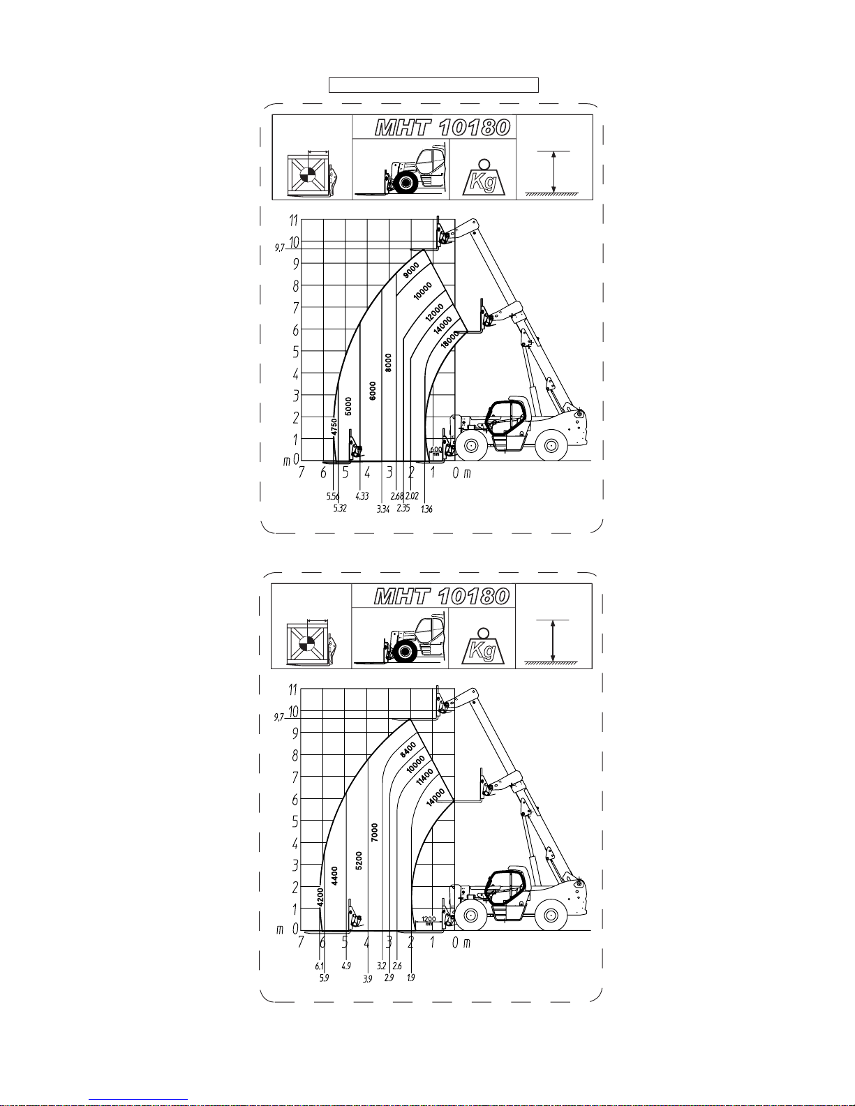
2-17
Ai sensi Normativa EN 1459-allegato B
in kg
18000
9,7 m
Kg
Forks
600 mm
908190
MHT 10180
MHT 10180
14000
9,7 m
Kg
Forks
1200 mm
908223
in Kg
MHT 10180
MHT 10180
Page 50
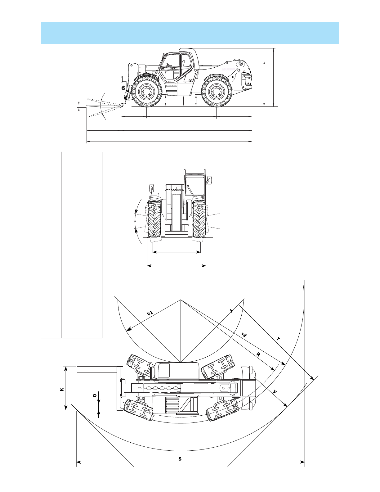
2-18
DIMENSIONS AND LOAD CHART
MHT 10225 LT-E3
U
M
I
B
C
AD
E
G2
G1
G
L
Y
Z
W
F
4°
4°
A 1800 mm
B 3650 mm
C 1350 mm
D 6860 mm
E 8660 mm
F 2000 mm
G 510 mm
G1 470 mm
G2 510 mm
I 1860 mm
K 2000 mm
L 100 mm
M 2325 mm
O 200 mm
R 5750 mm
S 12030 mm
T 5040 mm
U 2960 mm
V 7280 mm
V1 3160 mm
V2 6050 mm
W 2500 mm
Y 12°
Z 105°
Page 51
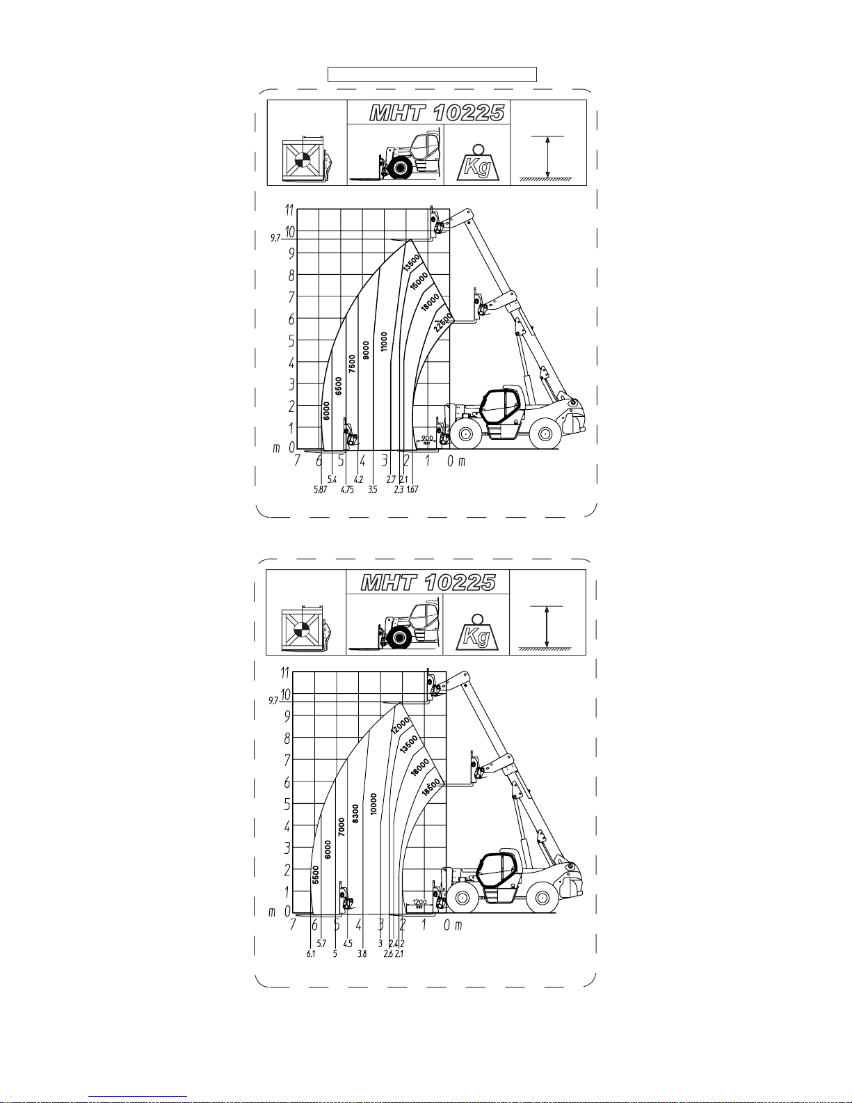
2-19
Ai sensi Normativa EN 1459-allegato B
22500
9,7 m
Kg
Forks
900 mm
908224
in Kg
MHT 10225
MHT 10225
18500
9,7 m
Kg
Forks
1200 mm
908225
in Kg
MHT 10225
MHT 10225
Page 52
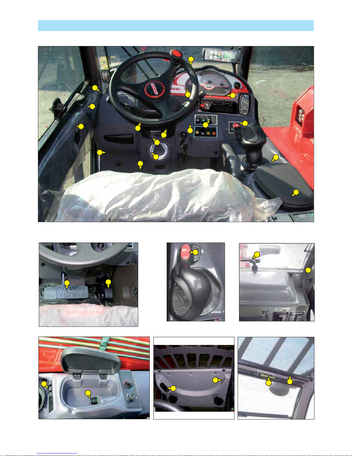
2-20
INSTRUMENTS AND CONTROLS
14
15
7
20
19
7
32
34
31
13
29
28
16
1
23
23
26
27
8
7
3
4
9
17
7
35
24
10
25
Page 53

2-21
DESCRIPTION
1 - DRIVER’S SEAT
2 - SAFETY BELT
3 - CONTROL AND SIGNAL LIGHTS PANEL
4 - LONGITUDINAL STABILITY LIMITER AND WARNING DEVICE
5 - EMERGENCY STOP BUTTON
6 - EMERGENCY EXIT
7 - SWITCHES
8 - LIGHT SWITCH, HORN AND INDICATOR SWITCH
9 - FRONT AND REAR WINDSCREEN WIPER SWITCH
10 - IGNITION SWITCH
11 - FUSES AND RELAYS IN THE CAB
12 - FUSES AND RELAYS UNDER THE ENGINE HOOD (NOT ILLUSTRATED)
13 - DIAGNOSTIC SOCKET
14 - ACCELERATOR PEDAL
15 - SERVICE BRAKE PEDAL AND TRANSMISSION CUT-OFF
16 - FORWARD/NEUTRAL/REVERSE GEAR SELECTION
17 - HYDRAULIC CONTROLS AND TRANSMISSION CUT-OFF
18 - FUNCTION FILES
19 - LEVEL INDICATORS
20 - HEATER CONTROL
20 - AIR CONDITIONING CONTROLS (OPTION AIR CONDITIONING)
21 - CAB FILTER VENTILATORS
22 - WINDSCREEN DEMISTER VENTS
23 - HEATING VENTS
24 - BRAKE FLUID RESERVOIR AND WINDSCREEN WASHER ACCESS PANEL
25 - STEERING WHEEL REGULATING HANDLE
26 - DOOR LOCK
27 - LOCKING HANDLE FOR UPPER HALF-DOOR
28 - UNLOCKING BUTTON FOR UPPER HALF DOOR
29 - HANDLE FOR REAR WINDOW OPENING
30 - DOCUMENT HOLDER
31 - SUN VISOR
32 - OVERHEAD LIGHT
33 - HOOK
34 - CIGAR LIGHTER
35 - ARMREST AND STORAGE
36 - CAR RADIO (OPTION)
37 - INSIDE REAR-VIEW MIRROR (OPTION) (NOT ILLUSTRATED)
38 - NUMBER PLATE (NOT ILLUSTRATED)
39 - NUMBER PLATE LIGHTING (NOT ILLUSTRATED)
40 - REAR REFLECTORS (NOT ILLUSTRATED)
41 - FRONT LIGHTS (NOT ILLUSTRATED)
42 - REAR LIGHTS (NOT ILLUSTRATED)
43 - FLASHING LIGHT (NOT ILLUSTRATED)
NOTE: All the terms such as: RIGHT, LEFT, FRONT, REAR are meant for an observer seated on driver’s seat and looking
in front of him.
Page 54

2-22
1 - DRIVER’S SEAT
DESIGNED FOR MAXIMUM COMFORT, THIS SEAT CAN BE ADJUSTED AS FOLLOWS.
WEIGHT ADJUSTMENT (FIG. A)
It is advised that the weight be adjusted when the driver is not sitting in the cab.
- Refer to graduation 1 of the seat.
- Turn handle 2 depending on the driver’s weight.
NOTE: To avoid any health problems, it is recommended that the weight should be checked and
adjusted before starting up the lift truck.
SEAT HEIGHT ADJUSTMENT (FIG. B)
- Raise the seat to the desired position, until you hear the ratchet click. If you raise the seat
above the last notch (stop), the seat drops down to the lowest position.
SEAT BACK-REST ANGLE ADJUSTMENT (FIG. C)
The back-rest angle of the seat may be adjusted to suit the individual.
- Press the left-hand button while pushing on the seat or relaxing pressure on the seat to find
a comfortable position.
SEAT DEPTH ADJUSTMENT (FIG. D)
The depth of the seat may be adjusted to suit the individual.
- Press the right-hand button while raising or lowering the seat to find the desired position.
EXTENDING THE HEAD-REST (FIG. E)
- The height of the back-rest can be adjusted by pulling it upwards (the notches will click) up
to the stop.
- The head-rest can be removed by applying sufficient pressure to pull it off the stop.
D
E
B
C
A
2
1
Page 55

2-23
LUMBAR ADJUSTMENT (FIG. F)
This increases the comfort of the seat and the driver’s freedom of movement.
- Turn the handle either left or right to adjust the height or depth of the lumbar support.
ADJUSTMENT OF THE ANGLE OF THE BACK-REST (FIG. G)
- Support the back-rest, pull the lever and position the back-rest to find the desired position.
If you do not support the back-rest when making adjustments, it swings completely forwards.
LONGITUDINAL ADJUSTMENT (FIG. H)
- Adjust the locking lever until you reach the position required. This then locks and the seat will
not shift into another position.
MAINTENANCE (FIG. I)
Dirt may adversely affect the correct functioning of the seat. For this reason, make sure your
seat is always clean.
- To clean or change the cushions, simply remove them from the seat frame.
A rocking head-rest increases the risk of an accident !
Avoid wetting the cushion fabric when cleaning. Check the resistance of the fabric on a small
hidden area before using any fabric or plastic cleaner.
F
G
H
I
Page 56
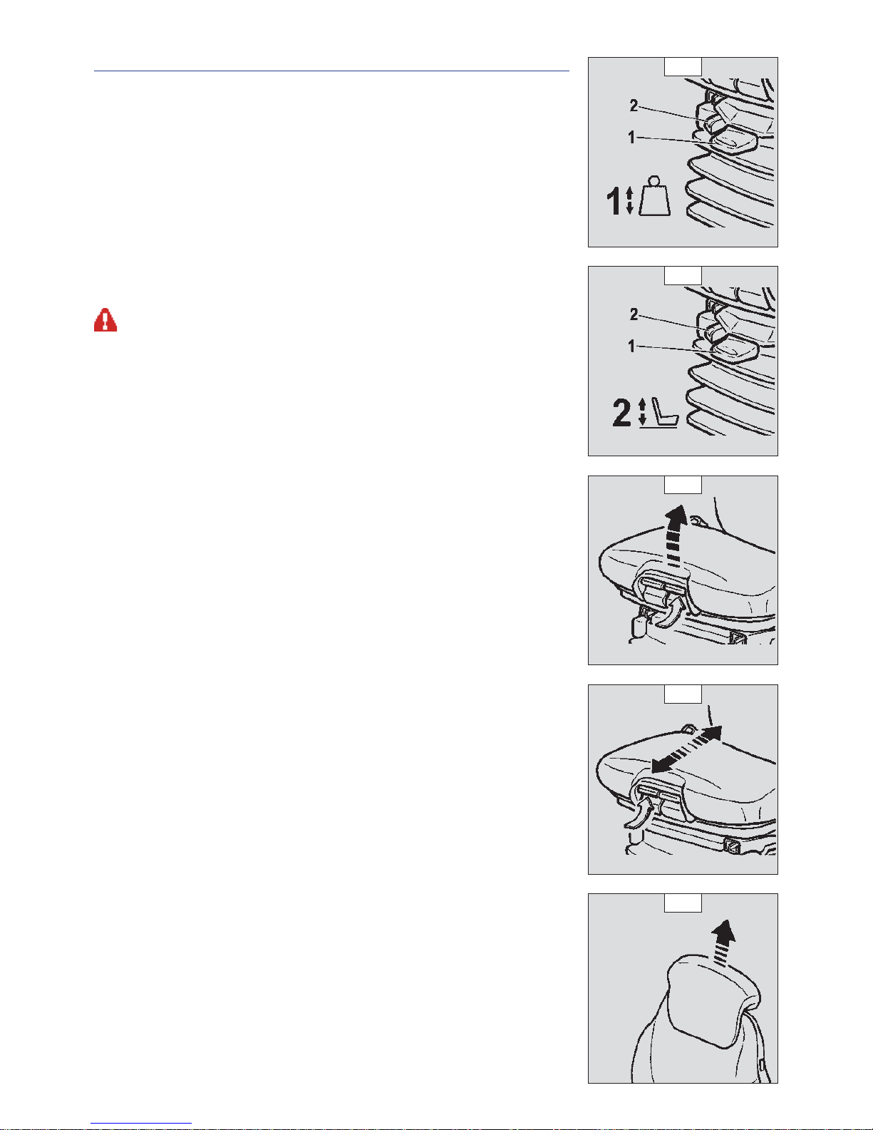
2-24
1 - BASIC PNEUMATIC DRIVER’S SEAT (OPTION)
DESIGNED FOR MAXIMUM COMFORT, THIS SEAT CAN BE ADJUSTED AS FOLLOWS.
WEIGHT ADJUSTMENT (FIG. A)
It is advised that you adjust the seat according to your weight when sitting.
- Switch on lift truck ignition.
- Push or pull lever 1 until green appears in display 2 indicating correct adjustment according
to your weight.
NOTE: To avoid any health problems, it is recommended that the weight should be checked and
adjusted before starting up the lift truck.
SEAT HEIGHT ADJUSTMENT (FIG. B)
When weight adjustment has been carried out, you can then modify seat height.
- Keep the ignition on in the lift truck.
- Push or pull lever 1 until green appears and adjust the height of the seat while checking that
the green in display 2 remains visible.
To avoid causing any damage, do not activate the compressor for over 1 minute.
SEAT BACK-REST ANGLE ADJUSTMENT (FIG. C)
The back-rest angle of the seat may be adjusted to suit the individual.
- Press the left-hand button while pushing on the seat or relaxing pressure on the seat to find
a comfortable position.
SEAT DEPTH ADJUSTMENT (FIG. D)
The depth of the seat may be adjusted to suit the individual.
- Press the right-hand button while raising or lowering the seat to find the desired position.
EXTENDING THE HEAD-REST (FIG. E)
- The height of the back-rest can be adjusted by pulling it upwards (the notches will click) up
to the stop.
- The head-rest can be removed by applying sufficient pressure to pull it off the stop.
D
E
A
B
C
Page 57
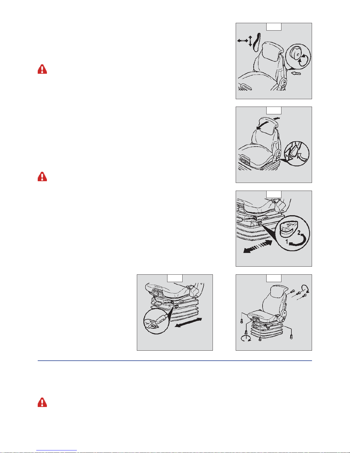
2-25
LUMBAR ADJUSTMENT (FIG. F)
This increases the comfort of the seat and the driver’s freedom of movement.
- Turn the handle either left or right to adjust the height or depth of the lumbar support.
ADJUSTMENT OF THE ANGLE OF THE BACK-REST (FIG. G)
- Support the back-rest, pull the lever and position the back-rest to find the desired position.
If you do not support the back-rest when making adjustments, it swings completely forwards.
HORIZONTAL SHOCK ABSORBER (FIG. H)
In certain conditions (e.g. driving with a trailer) it is advised that a horizontal shock absorber be
used. The driver’s seat is thus better able to absorb jerks in the direction of travel.
- Position 1: Horizontal shock absorber fitted.
- Position 2: Horizontal shock absorber removed.
LONGITUDINAL ADJUSTMENT (FIG. I)
- Adjust the locking lever until you reach the position required. This then locks and the seat will
not shift into another position.
SERVICING (FIG. J)
Dirt may adversely affect the correct functioning of the seat. For this reason, make sure your
seat is always clean.
- To clean or change the cushions, simply remove them from the seat frame.
A rocking head-rest increases the risk of an accident !
Avoid wetting the cushion fabric when cleaning. Check the resistance of the fabric on a small
hidden area before using any fabric or plastic cleaner.
2 - SAFETY BELT
- Sit correctly on the seat.
- Check that seat belt is not twisted.
- Place the seat belt at hip level.
- Attach the seat belt and check that it locks.
- Adjust the seat belt to your body shape without squeezing your hip and without over-slack.
In no event should the lift truck be used if the seat belt is defective (fixing, locking, cuts, tears, etc.). Repair or replace the seat belt immediately.
F
G
J
H
I
Page 58

2-26
3 - CONTROL AND SIGNAL LIGHTS PANEL
CONTROL INSTRUMENTS
A - I.C. ENGINE WATER TEMPERATURE
Temperature zone:
A1 - White zone (0° - 50°) Use the lift truck with moderation, wait for temperature to increase before normal operation.
A2 - White zone (50° - 100°) Use lift truck normally
A3 - White/red zone (100° - 105°) Use lift truck with moderation, monitor the temperature.
A4 - Red zone (105° - 120°) Stop the lift truck, look for the cause of overheating.
B - HOUR METER AND REV COUNTER
C - FUEL LEVEL
Red zone C1 indicates that you are using the reserve supply and that time of use is limited.
D - STEERING TYPES SELECTOR
To select from the three different steering options turn knob D as follows:
D1: front and rear steering wheels.
D2: front steering wheels.
D3: wheel in oblique position (crab steering).
Before selecting a type of steering, check the ALIGNMENT OF THE REAR AND FRONT WHEELS .
SIGNAL LIGHTS
A permanently lit or flashing warning lamp, with the engine running, is the sign of an operating fault. The lighting of some
lamps may be accompanied by an audible signal. Do not ignore this warning, consult your dealer without delay.
If one of the warning lamps comes on while the lift truck is in motion, stop the lift truck under the safest possible conditions.
When activating the electrical system of the lift truck, all the red and orange lamps and the panel’s buzzer must light to indicate their
good working order. If one of the red lamps or the buzzer does not function, carry out the necessary repairs.
RED I.C. ENGINE WARNING INDICATOR LIGHT
If the lamp comes on or flashes while the lift truck is in operation, a diagnostic fault has been detected. The lift truck will operate
in reduced mode. Consult your dealer without delay.
YELLOW I.C. ENGINE PREHEATING INDICATOR LIGHT
Preheating is necessary. When the lift truck is switched on, the lamp comes on for 2 seconds and off as soon as preheating is
ended. Start the lift truck’s I.C. engine.
REAR WHEELS ALIGNMENT YELLOW INDICATOR LIGHT
Not used
FRONT WHEELS ALIGNMENT GREEN INDICATOR LIGHT
Not used
0
4/4
120
40
˚C
pm x
100
STOP
AR B
00000
00
electronic
B
AC
D
A1 A2 A3
A4
C1
D1
D2
D3
D
!
STOP
Page 59

2-27
GREEN SIDEWAYS OR CRAB MOVEMENT INDICATOR LIGHT
The green light on indicates the steering selection for sideways or crab movement.
GREEN SHORT STEERING INDICATOR LIGHT
The green light on indicates the short steering selection.
RED LIFT-TRUCK ELECTRONIC SYSTEM INDICATOR LIGHT
The lifting truck functions as a degraded mode. To consult your dealer as soon as possible.
YELLOW I.C. ENGINE PREHEATING INDICATOR LIGHT
Preheating is necessary. When the lift truck is switched on, the lamp comes on for 2 seconds and off as soon as preheating is
ended. Start the lift truck’s I.C. engine.
BATTERY CHARGE WARNING INDICATOR LIGHT
If the lamp and the buzzer come on when the lift truck is running, stop the I.C. engine immediately and look for the cause (electric
circuit, alternator belt, alternator, etc.).
RED I.C. ENGINE OIL PRESSURE WARNING INDICATOR LIGHT
If the lamp and the buzzer come on when the lift truck is running, stop the I.C. engine immediately and look for the cause (engine
oil level, possible leak, etc.).
RED PARKING BRAKE LAMP
This lamp comes on when the parking brake is applied.
RED STEERING SYSTEM OIL PRESSURE WARNING INDICATOR LIGHT
If the lamp comes on when the lift truck is running, stop the I.C. engine immediately and look for the cause (possible leak, etc.).
RED AIR FILTER OR HYDRAULIC RETURN FILTER CLOGGED INDICATOR LIGHT
The lamp and buzzer come on when the air filter cartridge or the hydraulic return oil filter cartridge is clogged up. Stop the I.C.
engine and carry out the necessary repairs (see cleaning and replacement requirements in chapter: 3 - MAINTENANCE: FILTERS
CARTRIDGES AND BELTS).
RED BRAKING OIL LEVEL WARNING INDICATOR LIGHT
If the lamp and the buzzer come on, when the lift truck is running, stop the I.C. engine immediately and look for the cause
(braking oil level, possible leak, etc.). In the event of an abnormal dropping of the level, consult your dealer.
RED SAFETY SYSTEM EXCLUDING INDICATOR LIGHT
If the indicator light and the buzzer sounds security system is disabled.
GREEN DIRECTION INDICATOR LAMP
GREEN SIDELIGHTS LAMP
BLUE MAIN BEAM LAMP
YELLOW CENTRAL DIFFERENTIAL BLOCK INDICATOR LIGHT
ARB
Page 60

2-28
4 - LONGITUDINAL STABILITY LIMITER AND WARNING DEVICE
This device warns the operator of the lift truck’s longitudinal stability limits. However, lateral stability can reduce the load chart in the
upper part, and this reduction is not detected by the device.
According to the type of work required, the longitudinal stability limiter and warning device allows the operator to operate the lift truck
in complete safety.
The operator must respect the lift truck’s load chart, and the operating mode according to the attachment.
A “HANDLING” MODE
B
“BUCKET” MODE
C
“SUSPENDED LOAD”
MODE
A - “HANDLING” MODE
Use on forks (TFF, PFB, TDL), and adjustable accessories on forks (BB, GL).
- By default, the device is in “HANDLING” MODE when the lift truck is started-up, except if the
“SUSPENDED LOAD” MODE has been selected before shutting-down the engine.
A1 - A2 - A3: There is a significant reserve of longitudinal stability.
A4 - A5: The lift truck is approaching the limit of longitudinal stability, move with care.
A6: The lift truck is very near at the limit of longitudinal stability. The alarm sounds simultaneously
with a slow intermittent sound. Move with care.
A7: The lift truck is very near at the limit of longitudinal stability. The alarm sounds simultaneously
with a fast intermittent sound. Move with extreme care.
A8: The lift truck is at the authorized limit of longitudinal stability. A continuous acoustic alarm
is simultaneously sounded. All “AGGRAVATING” hydraulic movements are cut-off. Cut-off
may be preceded by automatic slowing of hydraulic movements. Only perform hydraulic
movements that increase stability in the following order; retract and raise the jib.
NOTE: When the jib is retracted, the function for cutting-off “AGGRAVATING” hydraulic movements is
disconnected.
B - “BUCKET” MODE
Use with a bucket (CB, CBA, CBC, CBG, CBR, CBM, FFGR).
- Place the lift truck in the transport position.
- Press the button
for 2 seconds, the “BUCKET” MODE is confirmed by an audible beep
and the lighting of the lamp.
- Return to “HANDLING” MODE by pressing the button
, or loss of driver presence for a
few seconds, or shutting down the engine.
A1 - A2 - A3: There is a significant reserve of longitudinal stability.
A4 - A5: The lift truck is approaching the limit of longitudinal stability, move with care.
A6: The lift truck is approaching the limit of longitudinal stability. An audible beep
is sounded. Move with care.
A7: The lift truck is very close to the limit of longitudinal stability. Move with extreme care.
A8: The lift truck is at the authorized limit of longitudinal stability.
All hydraulic movements remain available, ONLY PERFORM DE-AGGRAVATING HYDRAULIC MOVEMENTS IN
THE FOLLOWING ORDER: RETRACT AND RAISE THE JIB.
NOTE: According to the version, the jib lowering and extension movements may be cut-off and preceded
by an automatic slowing of hydraulic movements. In this case, when the jib is retracted, the
function for cutting-off “AGGRAVATING” hydraulic movements is disconnected.
A8
A7
A6
A5
A4
A3
A2
A1
A8
A7
A6
A5
A4
A3
A2
A1
Page 61

2-29
C - “SUSPENDED LOAD” MODE
Use with crane jib (P, PC, PT, PO).
- Place the lift truck in the transport position.
- Press the button
for 2 seconds, “SUSPENDED LOAD” MODE is validated by an audible beep
and the lighting of the lamp.
- Return to “HANDLING” MODE by pressing the button
.
A1 - A2 - A3: There is a significant reserve of longitudinal stability.
A4 - A5: The lift truck is approaching the limit of longitudinal stability, move with care.
A6: The lift truck is very near at the limit of longitudinal stability. The alarm sounds simultaneously
with a slow intermittent sound. Move with care.
A7: The lift truck is very near at the limit of longitudinal stability. The alarm sounds simultaneously
with a fast intermittent sound. Move with extreme care.
A8: The lift truck is at the authorized limit of longitudinal stability. A continuous acoustic alarm
is simultaneously sounded. All “AGGRAVATING” hydraulic movements are cut-off. Cut-off may be preceded by automatic
slowing of hydraulic movements. Only perform hydraulic movements that increase stability in the following order; retract and
raise the jib.
NOTE: When the jib is retracted, the function for cutting-off “AGGRAVATING” hydraulic movements is disconnected.
D - KEY SELECTOR FOR DISCONNECTING THE LONGITUDINAL STABILITY LIMITER AND WARNING DEVICE
In certain cases, in order to get out of a difficult situation, the operator can bypass this safety system.
Key selector D temporarily disables the cutting-off of “AGGRAVATING” hydraulic movements.
-Keep key selector D turned in position “0” to proceed and simultaneously perform the necessary
”AGGRAVATING” hydraulic movement with extreme care. The combined use of these two actions is
limited to 60 seconds.
Remain very vigilant during this operation. The only information available to the operator is the lift truck’s
dynamic stability.
The safety system can be deactivated manually only in case of emergency and for reasons of safety
With the safety system deactivated, the operator and the truck are exposed to risks and there is nothing to prevent
overloading and/or tipping over of the vehicle.
Key selector D has two positions “1” and “0”:
- in position “1” the safety system is activated;
- in position “0” the safety system is deactivated.
During normal use, the key selector is turned to position “1”, the safety system is activated.
Key D is kept safe inside a safety box D2 placed behind the driver’s seat.
Break the safety glass to pick up the key D3.
Note: When the safety system is disenabled, an a warning light (ARB) D4 and allarm sound is
automatically activated to warn the driver and other persons who may be present in the area
of a possible danger situation.
When the emergency procedures have been completed the key must put back in the safety box and the safety
glass must be replaced.
.
A8
A7
A6
A5
A4
A3
A2
A1
D
D2
D1
D3
D4
Page 62

2-30
E - TESTING OF THE LONGITUDINAL STABILITY LIMITER AND WARNING DEVICE
- Short press the button
at any time to check the correct operation of the longitudinal stability limiter and warning device.
• Correct operation: All the leds light for two seconds and an audible beep is sounded.
NOTE: This test does not check the proper adjustment of the device that must be inspected daily or after every 10 hours of service (see:
3 - MAINTENANCE: A - DAILY OR EVERY 10 HOURS SERVICE).
F - FAULT INDICATOR LAMP
A permanently lit fault indicator lamp F, together with a combination of illuminated leds, indicates a
major fault liable to affect the safety of the lift truck. Refer to your agent or dealer.
- The fault indicator lamp
plus leds A1 and A7 lighting alternately with A4 and A8 indicates
a defective link in the operation of the longitudinal stability limiter and warning device.
- The fault indicator lamp
plus continuously lit leds A7 and A8 indicate a faulty box.
G - STRAIN GAUGE
Disassembly or calibration of the strain gauge is prohibited, this must only be done by specially trained
personnel, consult your dealer.
A8
A7
A4
A1
F
G
Page 63

2-31
5 - EMERGENCY STOP BUTTON
- In the event of danger, it lets you stop the I.C. Engine and thereby cut out all hydraulic
movements.
- Pull the button to disable it before restarting the lift truck.
Be ready for hydraulic movements suddenly stopping when you press this button.
6 - EMERGENCY EXIT
IEMERGENCY HAMMERUse the emergency hammer to break one of the windows in the event
that it is impossible to exit the cab by the door or by opening the rear window.
7 - SWITCHES
NOTE: The location of the switches may vary depending on the options.
A - PARKING BRAKE SWITCH
Two-position luminous switch with safety block.
The parking brake acts on the front axle.
- To release the brake, press the pushbutton in position A1”.
- To lock the brake, press the pushbutton in position A2.
To release the brake from A2 to A1, while pressing the switch, act on safety lock .
B - REAR FOG LIGHT SWITCH
Two-position luminous switch.
C - EMERGENCY WARNING LIGHTS SWITCH
D - CENTRAL DIFFERENTIAL BLOCK PUSHBUTTON
Differential block pushbutton is used when the machine does not have optimum road
grip.
On selecting the button the central differential of the truck is blocked and torque is
transmitted to both the front and rear axles.
To block the central differential, carry out the following operations :
- stop carriage movement completely
- keep the I.C. engine running at minimum speed
- push the brake pedal all the way and press the differential block pushbutton “D”
- keeping the differential block pushbutton “D” pressed, gradually accelerate the I.C. engine to
obtain the required movement.
When the green light is ON it indicates selection of slow speed.
X - OPTION
5
B A
X
X
X
A1
A2
X
D
C
Page 64
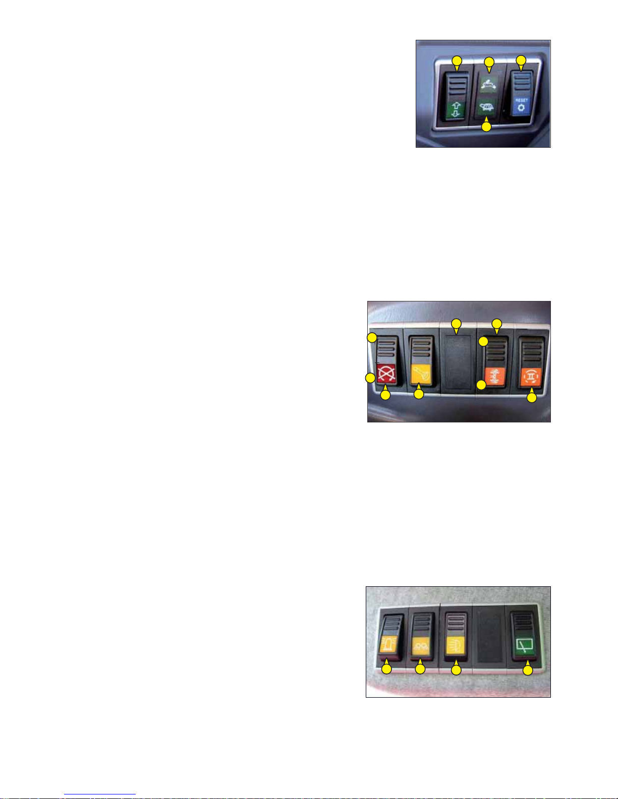
2-32
E - RUNNING SELECTOR (SLOW-FAST) .
The machine has two speeds :
- Slow (work site speed)
- Fast (for road travel)
To change the speed follow the instructions given below:
- stop vehicle movement completely
- keep the I.C. engine running at minimum speed
- set the reverse gear in idle (see point)
- push the brake pedal down all the way and press the fast-slow E button till the
respective light E1 or E2 switches on.
If the forward or reverse speed is not engaged, follow the instructions given below :
- set the reversal lever in the required position (Forwards - Backwards)
- discharge pressure from the brake pedal
- press the “RESET TRANSMISSION” button D to engage in the required direction.
- If the vehicle does not move, accelerate the I.C. engine slowly and gradually till
the truck starts moving.
These instructions must be followed for proper working of the transmission.
F - RESET TRANSMISION.
In normal operating conditions, the button is illuminated.
For more detailed information on use, see point “E”.
O - OPTIONAL DISCONNECT SWITCH (accessories hydraulic block)
The two-position switch is used for activating or deactivating the optional.
With the switch pressed in pos. “O1” (red indicator light On) the Optional/
accessories hydraulic block function is activated.
With the switch pressed in pos. “O2” (red indicator light Off) the Optional/
accessories hydraulic block function is deactivated.
P - STOPPING HYDRAULIC MOVEMENTS
While travelling on roads, it is advisable (compulsory in Italy and Germany) to stop
all hydraulic movements.
The indicator lights up when the movements are being used.
Q - LEVELLING CONTROL PUSHBUTTON
The pushbutton has two positions; it controls the truck level correction movements
to the right and left.
- pressing the button in position “Q1” will level the truck on the left
- pressing the button in position “Q2” will level the truck on the right
Verify the correct levelling using the sprit level placed in the cab .
N. B.: The levelling operation is not possible when the telescopic boom is inclined
beyond approx. 30° from the ground.
R - 2°/3° HYDRAULIC EXIT SWITCH (OPTIONAL)
The switch has two or three positions depending on the machine setup.
It is used for switching the hydraulic control for making two or three hydraulic
movements using the accessory.
S - ROTARY BEACON SWITCH
Two-position switch for turning the rotary beacon light on/off.
T - FRONT AND REAR WORK LIGHTS SWITCH (OPTIONAL)
Three-position switch for turning the work lights On/off.
U - SWITCH FOR WORK LIGHT AT THE TOP OF THE BOOM (OPTIONAL)
Z - SWITCH FOR ROOFTOP WINDOW WIPER (OPTIONAL)
T
Z
S
U
P
R
01
Q
02
O
X
Q1
Q2
E
E1
F
E2
Page 65

2-33
8 - LIGHT SWITCH, HORN AND INDICATOR SWITCH
The switch controls the visual and sound alarms.
A - All lights are off, the direction indicators do not flash.
B - The right hand direction indicators flash.
C - The left hand direction indicators flash.
D - The sidelights and the rear lights are on.
E - The dipped headlights and the rear lights are on.
F - The main beam headlights and the rear lights are on.
G - Headlight signal.
Pressing the switch sounds the horn.
NOTE: The positions D - E - F - G can be carried out without the ignition being on.
9 - FRONT AND REAR WINDSCREEN WIPER SWITCH
FRONT WINDSCREEN WIPER
A - Front windscreen wiper off.
B - Front windscreen wiper low speed setting.
C - Front windscreen wiper high speed setting.
D - Front windscreen wiper intermittent setting.
REAR WINDSCREEN WIPER
E - Rear windscreen wiper off.
F - Rear windscreen wiper on.
NOTE: These functions will only work when the ignition is switched on.
10 - IGNITION SWITCH
The key switch has four positions:
O - Ignition switched off and I.C. engine stopped.
I - Ignition and pre-heating.
II - Not used.
III - The I.C. engine starts, return to position I as soon as the key is released.
F E G
G
GA
D
B
C
A
B
A
C
D
D
D
A
B
C
E
F
I
II
0
III
Page 66
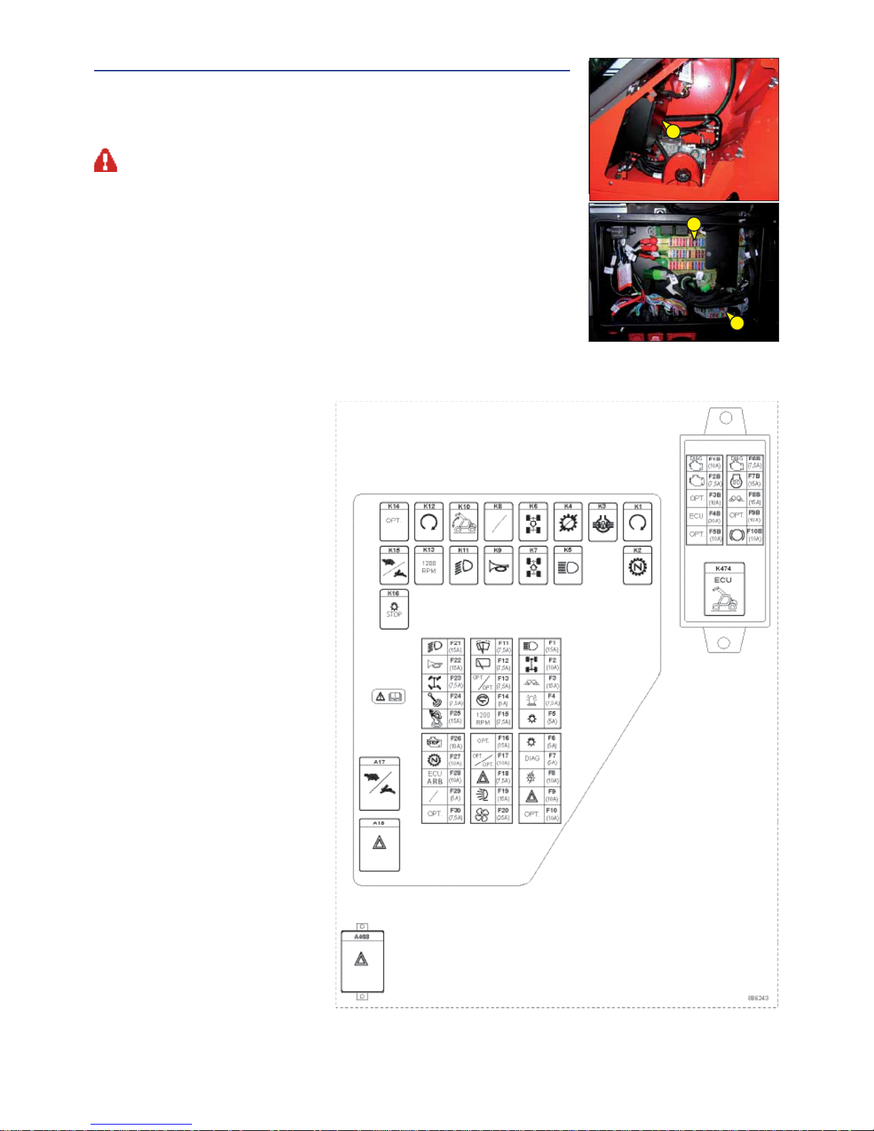
2-34
11 - FUSES AND RELAYS IN THE CAB
Remove the door that provides access to the fuses and relays 1
NOTE: A sticker on the inside of the access panel gives a clear display of the use of the
components described below.
Always replace a faulty fuse with another of equivalent rating. Never use a fuse that has been repaired.
A17 – Slow-fast relay
A18 - Warning relay.
A468 - Relay services
F1 - Headlights (15A).
F2 -
Axles alignment power supply(10A)
F3 - Rear
work lights (15A)
F4 - Rotating lamp (7,5A).
F5 -
Position lights (5A)
F6 -
Position lights (5A)
F7 - +15 /
diagnostics power supply (5A).
F8 -
Light switch/rear fog lights power supply (10A).
F9 - +30 / warning (10A).
F10 - +30 / Radio/ antitheft (10A).
F11 -
anterior windshield wiper switch (7,5A).
F12 -
rear windshield wiper power supply (7,5A).
F13 - pneumatic seat / radio (7,5A).
F14 - Siège micro /
indicator lights and
instruments (5A).
F15 - Valve 1200 RPM (7,5A).
F16 - +15 OPTIONAL (15A)
F17 - OPTION 2°/3° predispositions
Hydraulic (10A).
F18 - +15 warning (7,5A)
F19 -
boom work lights (15A)
F20 - ventilation /
heating (55A)
F21 - Low beams (15A).
F22 -
Horn (15A).
F23 - Steering sector (7,5A).
F24 - Boom
hydraulic movements (7,5A).
F25 - Joystick (J.S.M.) (15A).
F26 -
mushroom-shaped emergency
pushbutton (10A).
F27 - Neutral gear (10A).
F28 - Longitudinal stability limiter and warning
device (10A)
F29 - +15 antitheft (5A).
F30 - + 15 / predisposition (7,5A)
K1 - Consensus start relay
K2 - Neutral gear relay
K3 - Central differential block relay
K4 -
Transmission cut off relay
K5 - Headlights relay
K6 -
Reverse movement relay
K7 - Forwards movement relay
K8 - Option
K9 - Horn relay
K10 - Boom
hydraulic movements relay
K11 - Low beams relay
K12 - Engine consensus
K13 - Valve 1200 RPM relay
K14 - Option
K15 - Change gear relay
K16 -
Brake light relay
F1B - +30 engine electronic
F2B - +30 Engine diagnostic
F3B - +30 Radio
F4B - +15
Lift-truck electronic system
F5B - +30 Basket OPTION
F6B - +15 Engine diagnostic
F7B - +15 Fuel filter pre-heating
F8B - +15 Front work lights
F9B - +15 Basket
F10B - +15 Emergency Brake (OPTION)
K474 - “VP” Lift-truck electronic system
11
Page 67
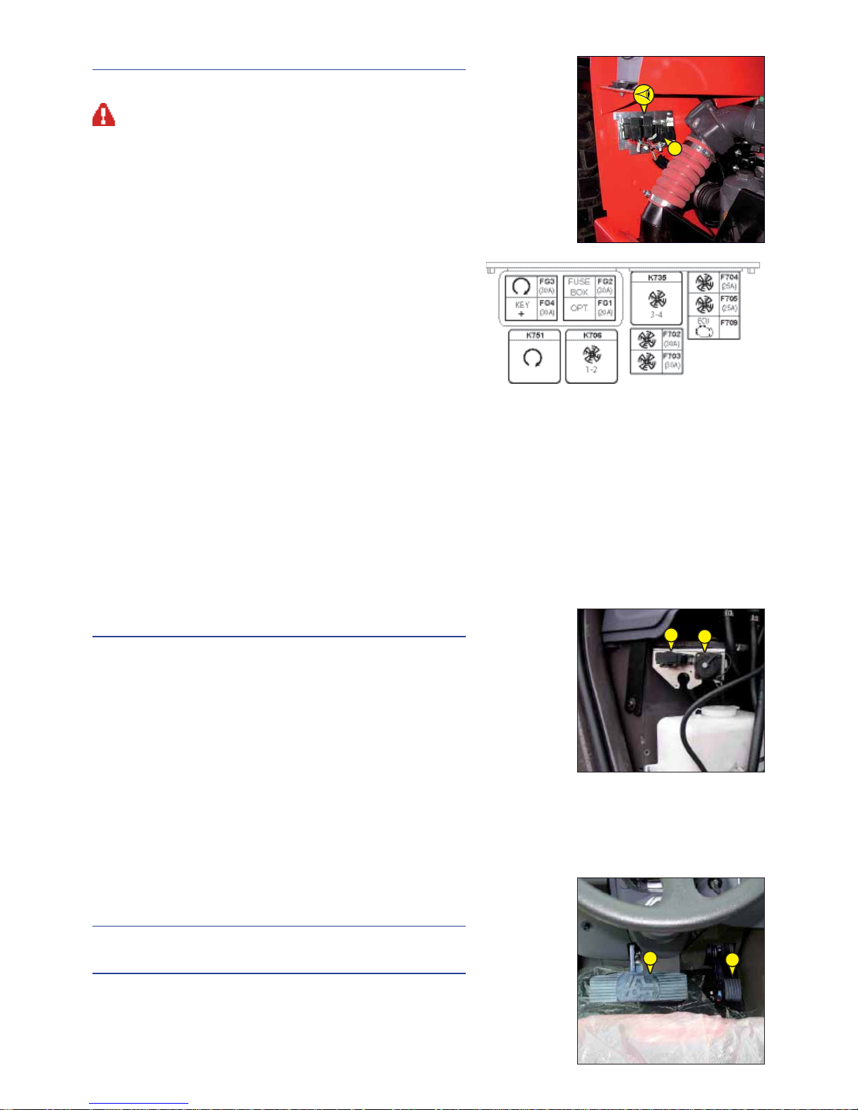
2-35
12 - FUSES AND RELAYS UNDER THE ENGINE HOOD
Remove casing 1 and cover 2 for access to fuses and relays.
Always replace a faulty fuse with another of equivalent rating. Never use a fuse that
has been repaired.
FG1 - OPTIONAL 30 (20A).
FG2 - Fuse and relay unit (30A)
FG3 - Start engine relay (30A).
FG4 - +30 key (30A)
F702 - Electric fan 1 (25A)
F703 - Electric Fan 2 (25A)
F704 - Electric Fan 3 (25A)
F705 - Electric Fan 4 (25A)
F709 - 30 Mercedes Unit
K706 - Electric Fan 1 and 2 Relays
K735 - Electric fans 3 and 4 Relays
K751 - Start engine Relay
13 - DIAGNOSTIC CONNECTOR
Remove the door that provides access to the diagnostic connector A.
A - Lift-truck electronic system
B - Mercedes electronic system
14 - ACCELERATOR PEDAL
15 - SERVICE BRAKE PEDAL AND TRANSMISSION CUT-OFF
The pedal applies on the front and rear wheels by an hydraulic brake system,
and allows the lift truck to be slowed down and stopped. Depending on the
position of the transmission cut-off switch, it enables the free travel to cut
off transmission (see: 2 - DESCRIPTION: 5 - SWITCHES).
12
14
15
B
A
Page 68

2-36
16 - FORWARD/NEUTRAL/REVERSE GEAR SELECTION
FORWARD: Push the knob forward (position A).
REVERSE: Pull the knob backwards (position B).
NEUTRAL: The knob must be in the intermediate position to start the lift truck (position C).
When operating this control, the lift truck should be travelling at slow speed and not accelerating.
NOTE: The reverse lights indicate that the lift truck is running in reverse motion. An OPTIONAL
audible reversing alarm can also be fitted.
SAFETY FOR MOVING THE LIFT TRUCK
Authorisation to move the lift truck is controlled by an electronic unit. The operator must
observe the following sequence to move the truck forwards or backwards:
1 - sit down correctly in the driver’s seat,
2 - release the parking brake,
3 - engage forward or reverse movement.
To stop the lift truck, he must observe the following sequence:
1 - Set the forward/reverse selector to neutral,
2 - engage the parking brake,
3 - get out of the lift truck.
NOTE: If the operator leaves the driving cab with forward or reverse engaged, a continuous alarm will sound. While this alarm sounds,
the operator can simply sit back in the seat and continue advancing or reversing.
If the alarm becomes discontinuous, the operator must sit back in the seat, put the forward/reverse selector back in neutral and
select forward or reverse if he wishes to continue moving.
A
C
B
Page 69
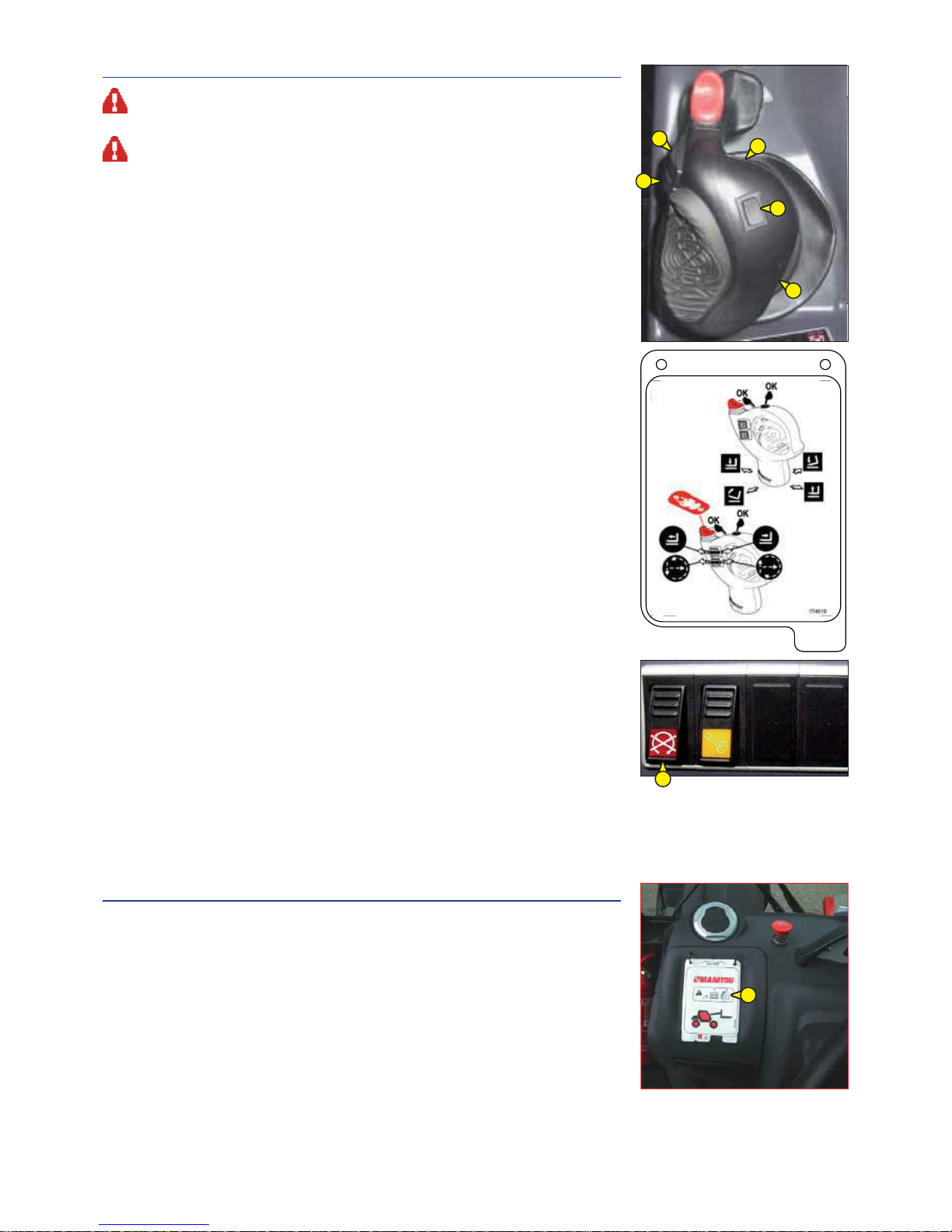
2-37
17 - HYDRAULIC CONTROLS AND TRANSMISSION CUT-OFF
Do not attempt to alter the hydraulic system pressure by interfering with the pressure regulating valve. In
the event of suspected malfunction, contact your dealer. ANY ALTERATION MAY RENDER THE WARRANTY
NULL AND VOID.
Use the hydraulic controls carefully without jerking, to avoid accidents caused by shaking the lift truck.
NOTE: When driving on the road, it is highly recommended (mandatory in Germany) that you
cut-off all the hydraulic movements (see: 2 - DESCRIPTION 7 - SWITCHES).
NOTE: If necessary use the steering to reset the hydraulic control steering accumulator.
A - Lifting and tilting control lever.
B - Telescoping control button.
C - Attachment control button.
LIFTING THE LOAD
- The lever A backwards when lifting.
- The lever A forwards when lowering.
TILT OF CARRIAGE
- The lever A to the left for reverse tilt.
- The lever A to the right for forward tilt.
TELESCOPING
- Button B forwards for extending.
- Button B backwards for retracting.
ATTACHMENT
- The button C forwards or backwards.
DECOMPRESSION OF OPTIONAL CIRCUIT
This operation must be carried out each time a lift truck supplementary accessory is to be
connected or disconnected.
1) Switch the combustion engine off and turn ignition key to position “I”.
2) Rotate roller “C” forwards and backwards, turn the roller for 3 seconds for each position
(pushbutton D pressed and red indicator light On).
When the operation is complete, the optional is depressurized; it will therefore be easier to
connect/disconnect the quick-release couplings on the top of the boom.
N. B. The operations must be carried out immediately after the combustion engine is switched
off, and not for more than 3 seconds for each command.
18 - FUNCTION TAB
These tab contain the description of the hydraulic controls and the load charts for the
attachments used on the lift truck.
A
B
C
211744
ok
ok
D
19
Page 70

2-38
19 - LEVEL INDICATOR
Enables the operator to check that the lift truck is in the horizontal position.
20 - HEATER CONTROL
A - HEATING FAN CONTROL
This 3-speed control regulates warm or cold air through the heating ventilators.
B - HEATING TEMPERATURE CONTROL
Allows the temperature inside the cab to be adjusted.
B1 - With the valve closed, the fan delivers fresh air.
B2 - With the valve opened completely, the fan delivers warm air.
The intermediate positions allow the temperature to be adjusted.
B1
B2
B
A
Page 71
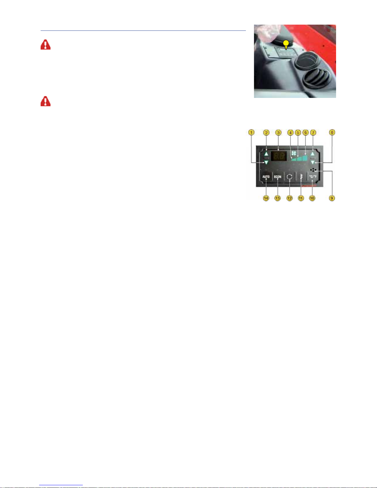
2-39
20 - AIR CONDITIONING CONTROLS (OPTION AIR CONDITIONING)
The air conditioning only comes on when the forklift truck has been started up. When using your air
conditioning, you must work with the doors and windows closed.
In winter: So as to ensure correct operation and complete efficiency of the air conditioning unit, start
up the compressor once a week, if only for a short spell, so as to lubricate the internal seals.
In cold weather: Warm the I.C. engine before switching on the compressor, so as to allow the coolant
that has collected in the liquid state at the lowest point of the compressor circuit to turn into gas under
the effect of the heat given off by the I.C. engine, as the compressor is liable to be damaged by coolant in
the liquid state.
If your air conditioning does not seem to be working properly, have it examined by your dealer (see: 3 -
MAINTENANCE: F - EVERY 2000 HOURS OF SERVICE). Never try to repair any possible problems by yourself.
21
LEGEND OF FUNCTIONS
1 – Internal temperature reduction 8 – Fan speed reduction command
2 – Internal temperature increase 9 – Internal air temperature sensor
3 – Preset temperature indicator 10 - °C / °F conversion and vice versa
4 – Fan 1st speed indicator 11 – External temperature reading command
5 – Fan 2nd speed indicator 12 – Recirculation command
6 – Fan 3rd speed indicator 13 - Compressor exclusion
7 – Fan speed increase command 14 – Restore automatic function
ERROR CODES
In case of a fault that affects the automatic regulation, the control unit displays an error code consisting of the letter E
followed by a number which identifies the type of fault according to the following Table:
E 1 external air temperature sensor (E.T.) interrupted.
E 2 external air temperature sensor (E.T.) short circuit.
E 3 cab air temperature sensor (I.T.) interrupted.
E 4 cab air temperature sensor (I.T.) short circuit.
E 5 mixed air temperature sensor (M.T.) interrupted.
E 6 mixed air temperature sensor (M.T.) short circuit.
Since automatic regulation is not possible, the keys for increasing and decreasing the internal temperature are used to
change the position of the mixer, while the fan speed is fixed at the 2nd speed.
When the error is solved, the control unit resumes normal operation only after resetting the + key.
Page 72
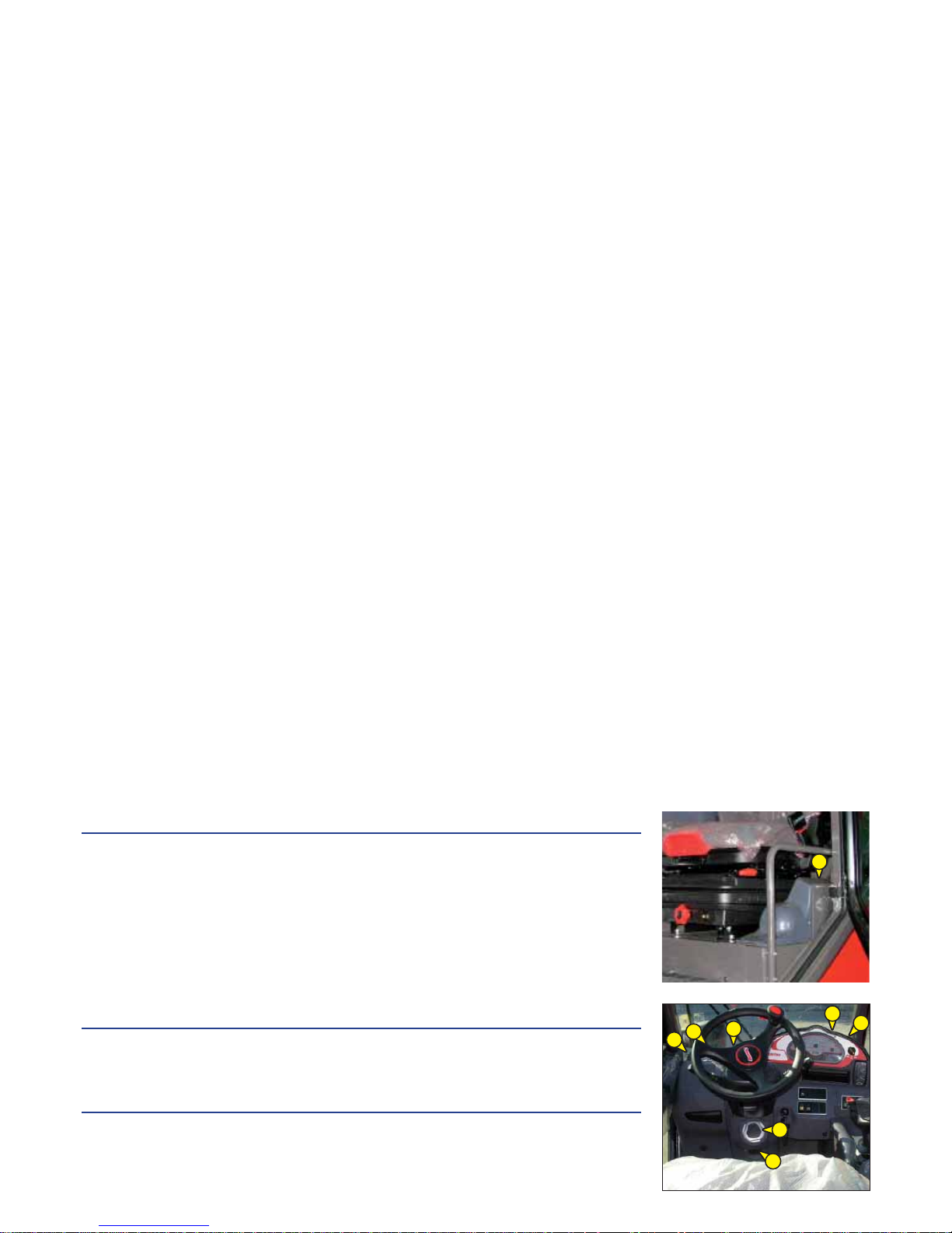
AIRCONDITIONING PLANT – CHECKING THE WORKING
Electronic control of the temperature (E.AC.C.)
To check to ensure the correct working of the heating and cooling system, make sure the engine is
started up with the hoods closed, at ambient temperature between +15°C and 30°C and the engine
cooling fluid sufficiently hot. If the ambient temperature is higher or lower than these values, the
system automatically adjusts itself in the maximum cooling or maximum heating conditions.
1 – Checking the water regulator valve
Press the cab internal temperature increase/decrease button, the water regulator valve shifts to the
maximum heating HI or maximum cooling LO condition. Make sure the mixed air temperature changes
accordingly.
2 – Checking the mixed air temperature sensor
If the sensor is defective, the following error codes appear on the display: E5 = Mixed air temperature
sensor (MT) open. E 6 = Mixed air temperature sensor (MT) short circuit.
3 – Checking the cab internal air temperature sensor
If the sensor is defective, the following error codes appear on the display: E5 = Internal air temperature
sensor (IT) open. E 6 = Internal air temperature sensor (IT) short circuit.
4 - Compressor activation
On pressing the ECON button, the relative LED lights up and switches off alternately and the compressor
is activated and deactivated, respectively, by means of the electromagnetic clutch.
5 – External air inlet and recirculation command
On pressing the Recirculation button, the relative LED lights up indicating the condition of ventilation
with recirculating air. On pressing the recirculation button again, the LED switches off indicating the
condition of ventilation with external air inlet.
6 – Fan speed command
The cab ventilation can be adjusted at three fan speeds: minimum, medium and maximum.
7 - °C and °F selection
When the relative LED is Off, the temperature is indicated in °C, when the LED is On the temperature
is read in °F (Fahrenheit).
The maximum cab temperature value setting is 37°C or 99°F.
8 – Checking the external temperature sensor
On pressing the external temperature button , the external temperature value appears on the display.
If the sensor is defective, the following error codes appear on the display:
E5 = External air temperature sensor (ET) open.
E6 = External air temperature sensor (ET) short circuit.
21 - CAB FILTER VENTILATORS
See: 3 - MAINTENANCE: D - EVERY 500 HOURS SERVICE.
22 - WINDSCREEN DEMISTER VENTS
For optimum effectiveness, close the heating ventilators.
23 - HEATING VENTS
These heating vents enable the air to be directed to the interior of the cabin and onto the side windows.
23
23
22
23
23
22
22
22
Page 73
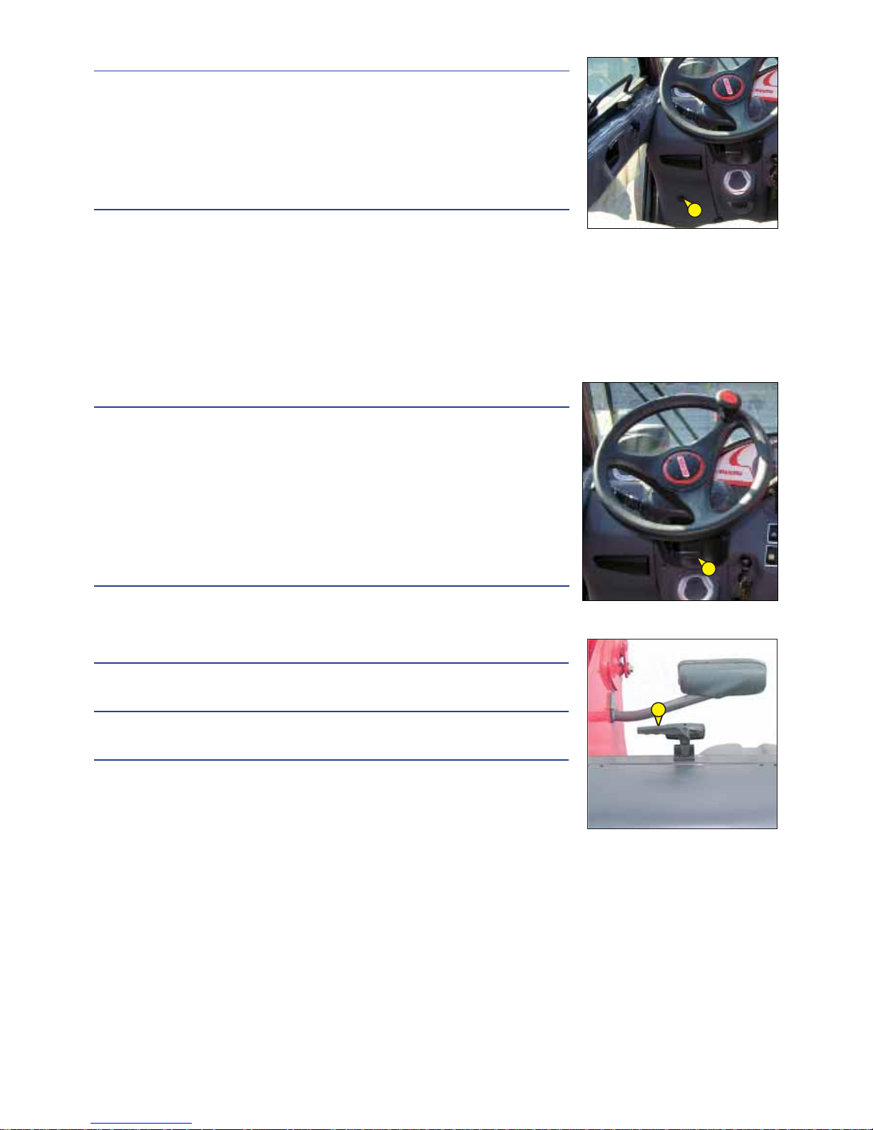
2-41
24 - BRAKING OIL AND WINDSCREEN WASHER TANK ACCESS PANEL
MHT 7140-E3
MHT 10160 LT-E3
- Loosen screw 1 and lift up the braking oil and windscreen washer tank access panel
(see: 3 - MAINTENANCE: B - EVERY 50 HOURS OF SERVICE).
24 - WINDSCREEN WASHER TANK ACCESS PANEL
MHT 10210 LT-E3
- Loosen screw 1 and lift up the braking oil and windscreen washer tank access panel
(see: 3 - MAINTENANCE: B - EVERY 50 HOURS OF SERVICE).
25 - STEERING WHEEL REGULATING HANDLE
This handle enables the angle and height of the steering wheel to be adjusted.
- Pull handle 1 to adjust the steering wheel.
- Push in handle 1 to lock the steering wheel in the desired position.
26 - DOOR LOCK
Two keys are provided with the lift truck to enable the cabin to be locked.
27 - LOCKING HANDLE FOR UPPER HALF-DOOR
28 - UNLOCKING BUTTON FOR UPPER HALF DOOR
29 - HANDLE FOR REAR WINDOW OPENING
EMERGENCY EXIT
Use the rear window as an emergency exit, in the event that it is impossible to leave the cab by
the door or by opening the windscreen.
NOTE: There is an OPTIONAL rear window stay.
1
1
Page 74

2-42
30 - DOCUMENT HOLDER
Ensure that the operator’s manual is in its place in the document holder.
31 - SUN VISOR
32 - OVERHEAD LIGHT
33 - HOOK
34 - CIGAR LIGHTER
For 12 V appliance and max. amperage 10A.
33
32
34
Page 75

2-43
35 - ARMREST AND STORAGE
- Lift the armrest 1 to access the storage.
36 - CAR RADIO (OPTION)
37 - INSIDE REAR-VIEW MIRROR (OPTION)
38 - NUMBER PLATE
39 - NUMBER PLATE LIGHTING
40 - REAR REFLECTORS
40
40
1
39
38
Page 76

2-44
41 - FRONT HEADLIGHTS
A - Left front indicator.
B - Left front dipped headlight.
C - Left front main beam.
D - Left front sidelight.
E - Right front indicator.
F - Right front dipped headlight.
G - Right front main beam.
H - Right front sidelight.
42 - REAR LIGHTS
A - Left rear indicator.
B - Left rear stoplight.
C - Left tail light.
D - Left rear reverse light.
E - Left rear fog light.
F - Right rear fog light.
G - Right rear reverse light.
H - Right tail light.
I - Right rear stoplight.
J - Right rear indicator.
43 - REVOLVING LIGHT
STANDARD
The revolving light pivots for space-saving on the lift truck and can be detached
to prevent theft.
- Loosen nut 1 and remove the revolving light.
- Protect mounting 2 with cap 3.
OPTIONAL AIR CONDITIONING
The magnetic revolving light must be clearly visible on the roof of the cab and plugged-in to
socket 1.
F G H I HA B C D E
F
H
G
E
B
A
C
D
1
3
1
2
Page 77

2-45
TOWING PIN AND HOOK
Located at the rear of the lift truck, this device is used to attach a trailer. Its capacity is limited for each lift truck by the Authorized Gross
Vehicle Weight, tractive force and maximum vertical force on the coupling point.
- To use a trailer, see current regulations in your country (maximum running speed, braking, maximum weight of trailer, etc.).
- Verify the trailer’s condition before using it (tyre condition and pressures, electrical connection, hydraulic hose, brake system…).
Do not tow a trailer or attachment which is not in perfect working order. Using a trailer in poor condition may affect the lift truck’s steering and braking, and
hence safety.
If a third party helps in coupling or uncoupling the trailer, this person must be permanently visible to the driver and wait until the lift truck has stopped, the
handbrake is on and the I.C. engine is switched off before performing the operation.
NOTE: A rear-view mirror allows the lift truck to approach more closely to the trailer ring.
A - COUPLING FITTING
COUPLING AND UNCOUPLING THE TRAILER
- To couple the trailer, position the lift truck as close as possible to the trailer ring.
- Put the handbrake on and switch off the I.C. engine.
- Remove the clip 1, lift the trailer pin 2 and place or remove the trailer ring.
Be careful not to get your fingers caught or crushed during this operation.
Do not forget to put clip 1 back in place.
When uncoupling, make sure that the trailer is supported independently.
1
2
1
2
1
2
Page 78

2-46
DESCRIPTION AND USE OF THE OPTIONS
1 - JIB SUSPENSION
2 - ATTACHMENT EASY HYDRAULIC CONNECTION
Page 79

2-47
1 - BOOM SUSPENSION
The boom is suspended to reduce shaking of the lift truck on rough ground (e.g. moving straw
in a field).
OPERATION
- Set the forks or attachment on the ground and relieve the front wheels a few centimetres only.
- Press switch 1 set to position A, the visual indicator comes on indicating that boom suspension
is activated.
- Press switch 1 set to position B, the visual indicator goes out indicating that boom suspension
is deactivated.
Boom suspension is active to a lifting height of 3m00 from the axis of ar ticulation of the carriage with
respect to the ground with the boom retracted. When you move beyond this height or make another hydraulic
movement (tilting, telescoping, attachment), boom suspension is momentarily deactivated and the visual
indicator of switch 1 goes out.
- When the I.C. engine is off, boom suspension is automatically deactivated.
2 - ATTACHMENT EASY HYDRAULIC CONNECTION
For easily connecting and disconnecting the attachment.
OPERATION
- Press for two seconds on push-button 1 to release the attachment circuit hydraulic pressure.
- Connect or disconnect the rapid connectors of the hydraulic attachment (see: 4 - OPTIONAL
ATTACHMENTS FOR USE WITH THE RANGE: PICKING UP THE ATTACHMENTS).
A
B
1
1
Page 80

Page 81

3-1
3 - MAINTENANCE
Page 82

3-2
Page 83

3-3
TABLE OF CONTENTS
MANITOU ORIGINAL SPARE PARTS AND EQUIPMENT
3-4
START-UP CHECKLIST
3-5
FILTERS CARTRIDGES AND BELTS
3-6
LUBRICANTS AND FUEL
3-7
SERVICING SCHEDULE
3-9
A - DAILY OR EVERY 10 HOURS SERVICE
3-11
B - EVERY 50 HOURS SERVICE
3-17
C - EVERY 250 HOURS SERVICE
3-23
D - EVERY 500 HOURS SERVICE
3-26
E - EVERY 1000 HOURS SERVICE
3-32
F - EVERY 2000 HOURS OF SERVICE
3-35
G - OCCASIONAL MAINTENANCE
3-37
Page 84

3-4
MANITOU ORIGINAL SPARE PARTS AND EQUIPMENT
OUR LIFT TRUCKS MUST BE SERVICED USING ORIGINAL MANITOU PARTS.
IF YOU USE PARTS WHICH ARE NOT ORIGINAL MANITOU PARTS,
YOU RISK
- Legally - to be held responsible in the event of an accident.
- Technically - to generate operating failure or shorten the life of the lift truck.
THE USE OF COUNTERFEIT PARTS OR COMPONENTS NOT APPROVED BY THE MANUFACTURER,
MEANS YOU LOSE THE BENEFIT OF THE CONTRACTUAL GUARANTEE.
BY USING ORIGINAL MANITOU PARTS FOR MAINTENANCE OPERATIONS,
YOU BENEFIT
Through its network, MANITOU provides the user with
EXPERTISE
- Know-how and competence.
- The guarantee of high-quality work.
- Original replacement components.
- Help with preventive maintenance.
- Efficient help with diagnosis.
- Improvements due to experience feedback.
- Operator training.
- Only the MANITOU network has detailed knowledge of the design of the lift truck and therefore the best
technical ability to provide maintenance.
ORIGINAL REPLACEMENT PARTS ARE DISTRIBUTED EXCLUSIVELY BY MANITOU AND ITS DEALER NETWORK.
the dealer network list is available on manitou web site www.manitou.com
Page 85

3-5
START-UP CHECKLIST
0 = OK 1 = Missing 2 = Incorrect
100 ENGINE
01 Air filter
02 Fuel tank
03 Fuel lines - Filter
04 Injection or carburetion system
05 Radiator and cooling system
06 Belts
07 Hoses
101 TRANSMISSION
01 Direction reversal system
02 Gear shift
03 Cut-off pedal
04 Clutch
102 AXLES/TRANSFER GEAR BOX
01 operation and seal
02 Stop settings
103 HYDRAULIC/HYDROSTATIC CIRCUIT
01 Tank
02 Pumps and couplings
03 Tightening of connections
04 Lift cylinder(s)
05 Tilt cylinder(s)
06 Attachment cylinder(s)
07 Telescope cylinder(s)
08 Compensation cylinder(s)
09 Steering cylinder(s)
10 Control Valve
11 Balancing valve
104 BRAKE SYSTEM
01 Service brake and parking brake operation
02 Brake fluid level
105 LUBRICATION AND GREASING
106 JIB/MANISCOPIC/MANIACCESS ASSEMBLY
01 Beam and telescope(s)
02 Skid
03 Hinges
04 Carriage
05 Forks
107 MAST ASSEMBLY
01 Fixed and mobile uprights
02 Carriage
03 Chains
04 Rollers
05 Forks
108 ATTACHMENTS
01 Fitting on machine
02 Hydraulic couplings
109 CABIN/PROTECTOR/ELECTRIC CIRCUIT
01 Seat
02 Dashboard and radio
03 Sound and visual alarm/safety system
04 Heating/Air conditioning
05 Windscreen wiper/windscreen washer
06 Road horn
07 Reversing horn
08 Road lights
09 Additional lights
10 Rotating beacon light
11 Battery
110 WHEEL
01 Rims
02 Tyre/Pressure
111 SCREWS
112 FRAME AND BODYWORK
113 PAINTING
114 GENERAL OPERATION
115 OPERATOR’S MANUAL
116 CUSTOMER INSTRUCTIONS
Page 86
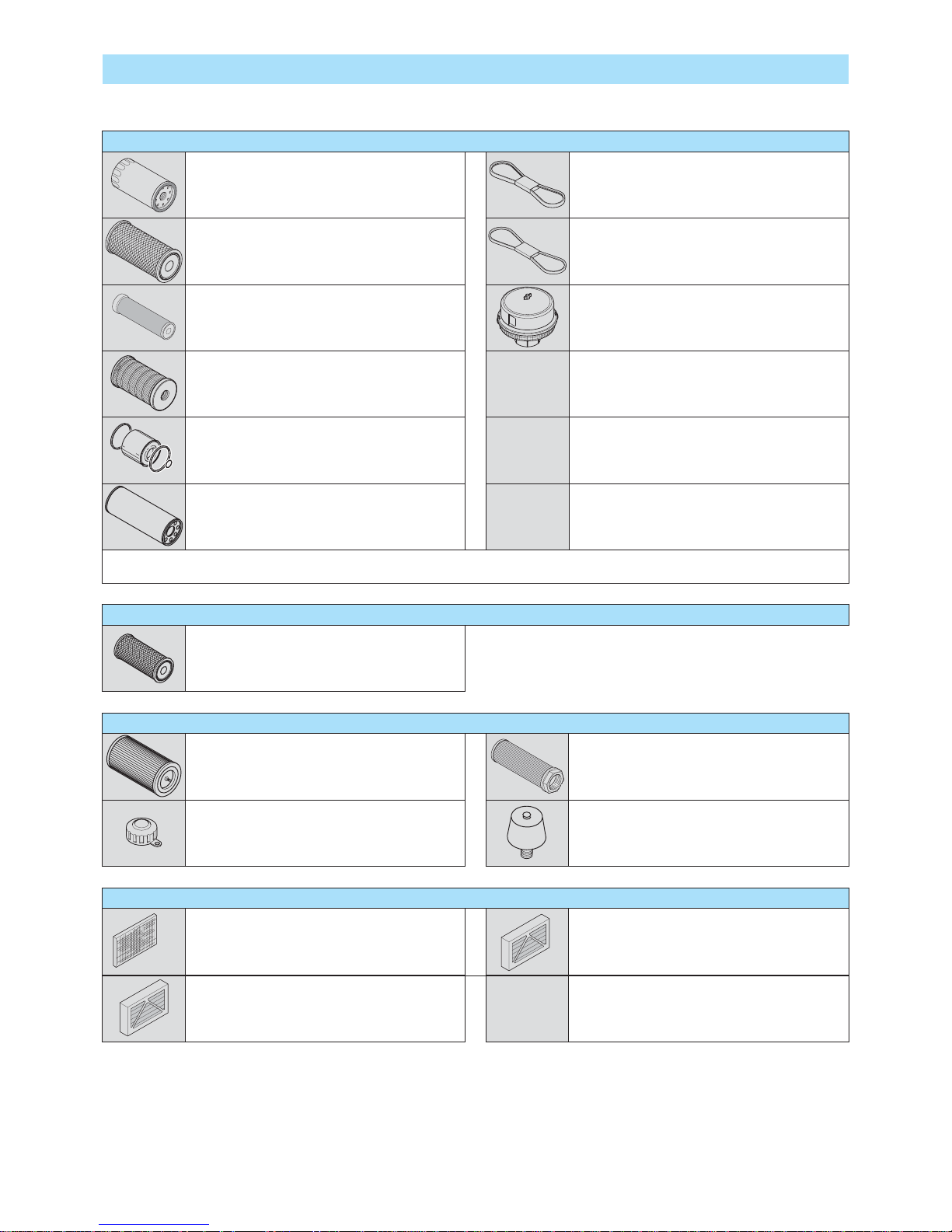
3-6
FILTERS CARTRIDGES AND BELTS
TRANSMISSION
GEAR BOX OIL FILTER
Part number: 485695
Change: 500 H
HYDRAULIC
HYDRAULIC RETURN OIL FILTER CARTRIDGE
Part number: 724670
Change: 500 H
SUCTION STRAINER FOR HYDRAULIC OIL TANK
Part number: 513752
Clean: 1000 H
FILTER CAP FOR HYDRAULIC OIL TANK
Part number: 586106
Change: 1000 H
SUCTION STRAINER FOR HYDRAULIC OIL TANK
Part number: 448269
Clean: 1000 H
CAB
FILTRE AIR EXTERNE CABINE
Part number: 882133
Clean: 500 H
CAB VENTILATION FILTER (WITH AIR CONDITIONING)
Part number: 780978
Clean: 50 H
Change: 250 H
I.C. ENGINE
I.C. ENGINE OIL FILTER
Part number: 709666
Change: 500 H
ALTERNATOR BELT
Part number: 739731
DRY AIR FILTER CARTRIDGE
Part number: 723755
Clean: 50 H*
Change: 500 H*
COMPRESSOR BELT
(OPTION AIR CONDITIONING)
Part number: 732364
SAFETY DRY AIR FILTER CARTRIDGE
Part number: 723754
Change: 1000 H*
AUTOMATIC VACUUM-CLEANING PRE-FILTER
(OPTION)
Part number: 688091
FUEL FILTER CARTRIDGE
Part number: 709664
Change: 500 H
FUEL PRE-FILTER
Part number: 709667
Change: 500 H
SAFETY CARTRIDGE FUEL PRE-FILTER
Part number: 709663
Change: 500 H
*:
This periodicity is given for information only (see: 3 - MAINTENANCE: SERVICING SCHEDULE) for cleaning and changing.
CAB VENTILATION FILTER (WITHOUT AIR CONDITIONING)
Référence: 22552
Nettoyer: 500 H
Page 87

Page 88

3-8
I.C. ENGINE
ORGANS TO BE LUBRICATED CAPACITY RECOMMENDATION PACKAGING PART NUMBER
I.C. ENGINE
15 + 0,8
Litres
MANITOU Oil
API CH4
5 l
20 l
55 l
209 l
1000 l
661706
582357
582358
582359
490205
COOLING CIRCUIT 16 Litres
Cooling liquid
(protection - 25°)
2 l
5 l
20 l
210 l
788245
788246
788247
788248
Cooling liquid
(protection - 35°)
20 l
210 l
1000 l
788249
788250
788251
FUEL TANK 200 Litres Diesel fuel (*)
LUBRICANTS AND FUEL
USE THE RECOMMENDED LUBRICANTS AND FUEL:
- For topping up, oils may not be miscible.
- For oil changes, MANITOU oils are perfectly appropriate.
DIAGNOSTIC ANALYSIS OF OILS
If a service or maintenance contract has been organized with the dealer, a diagnostic analysis of engine, gear box and axle oils may be
requested depending on the rate of use.
(*) RECOMMENDED FUEL SPECIFICATION
Use a high-quality fuel to obtain optimal performance of the I.C. engine.
• N590 diesel fuel type - Auto/C0/C1/C2/C3/C4
• BS2869 Class A2
• ASTM D975-91 Class 2-2DA, US DF1, US DF2, US DFA
• JIS K2204 (1992) Grades 1, 2, 3 and Special Grade 3.
TRANSMISSION
ORGANS TO BE LUBRICATED CAPACITY RECOMMENDATION PACKAGING PART NUMBER
GEAR BOX 4,4 Litres
MANITOU Oil
Automatic transmission
1 l
20 l
55 l
209 l
1000 l
62148
546332
546217
546195
720148
TRANSMISSION UNIVERSAL JOINT
MANITOU Grease
BLUE multi-purpose
400 g
1 kg
5 kg
20 kg
50 kg
161589
720683
554974
499233
489670
BOOM
ORGANS TO BE LUBRICATED RECOMMENDATION PACKAGING PART NUMBER
BOOM PADS
MANITOU Grease
BLACK multi-purpose
400 g
1 kg
5 kg
545996
161590
499235
GREASING OF THE BOOM
MANITOU Grease
BLUE multi-purpose
400 g
1 kg
5 kg
20 kg
50 kg
161589
720683
554974
499233
489670
Page 89

3-9
FRONT AXLE
ORGANS TO BE LUBRICATED CAPACITY RECOMMENDATION PACKAGING PART NUMBER
FRONT AXLE DIFFERENTIAL 35 Litres
MANITOU Oil
Special immersed brakes
5 l
20 l
209 l
1000 l
545976
582391
546222
720149
FRONT WHEELS REDUCERS 6 Litre
MANITOU Oil
SAE80W90
Mechanical transmission
2 l
5 l
20 l
55 l
209 l
499237
720184
546330
546221
546220
FRONT WHEELS REDUCERS PIVOTS
FRONT AXLE OSCILLATION
MANITOU Grease
BLACK multi-purpose
400 g
1 kg
5 kg
545996
161590
499235
REAR AXLE
ORGANS TO BE LUBRICATED CAPACITY RECOMMENDATION PACKAGING PART NUMBER
REAR AXLE DIFFERENTIAL 35 Litres
MANITOU Oil
Special immersed brakes
5 l
20 l
209 l
1000 l
545976
582391
546222
720149
REAR WHEELS REDUCERS 6 Litre
MANITOU Oil
SAE80W90
Mechanical transmission
2 l
5 l
20 l
55 l
209 l
499237
720184
546330
546221
546220
REAR WHEELS REDUCERS PIVOTS
REAR AXLE OSCILLATION
MANITOU Grease
BLACK multi-purpose
400 g
1 kg
5 kg
545996
161590
499235
CHASSIS
ORGANS TO BE LUBRICATED RECOMMENDATION PACKAGING PART NUMBER
TILTING CORRECTOR
MANITOU Grease
BLUE multi-purpose
400 g
1 kg
5 kg
20 kg
50 kg
161589
720683
554974
499233
489670
HYDRAULIC
ORGANS TO BE LUBRICATED CAPACITY RECOMMENDATION PACKAGING PART NUMBER
HYDRAULIC OIL TANK 200 Litres
MANITOU Oil
Hydraulic ISO VG 46
5 l
20 l
55 l
209 l
545500
582297
546108
546109
BRAKE
ORGANS TO BE LUBRICATED RECOMMENDATION PACKAGING PART NUMBER
BRAKE CIRCUIT
MANITOU Oil
Mineral brake fluid
1 l 490408
CAB
ORGANS TO BE LUBRICATED RECOMMENDATION PACKAGING PART NUMBER
CAB DOOR
MANITOU Grease
BLUE multi-purpose
400 g
1 kg
5 kg
20 kg
50 kg
161589
720683
554974
499233
489670
WINDSCREEN WASHER TANK Windscreen washer fluid
1 l
5 l
490402
486424
Page 90

3-10
SERVICING SCHEDULE
(1): MANDATORY 500 HOUR OR 6 MONTH SERVICE
This service must be carried out after approximately the first 500 hours of operation or within the 6 months following the start-up of the machine (whichever
occurs first).
A = ADJUST, C = CHECK, G = GREASE, N = CLEAN,
P = BLEED, R = REPLACE, V = DRAIN
PAGE
(1)
DAILY OR EVERY 10
HOURS SERVICE
EVERY 50 HOURS
SERVICE
EVERY 250 HOURS
SERVICE
EVERY 500 HOURS
SERVICE OR 6
MONTHS
EVERY 1000 HOURS
SERVICE OR 1 YEAR
EVERY 2000 HOURS
SERVICE OR 2 YEARS
EVERY 4000 HOURS
SERVICE
OCCASIONALLY
I.C. ENGINE
I.C. engine oil level
3-12 C C <<< <<< <<< <<< <<< <<<
Cooling liquid level
3-12 C C <<< <<< <<< <<< <<< <<<
Fuel level
3-13 C C <<< <<< <<< <<< <<< <<<
Fuel pre-filter
3-13 C C <<< <<< <<< <<< <<< <<<
Dry air filter cartridge
3-18/29 R C/N <<< R <<< <<< <<<
Radiator cores
3-18 N N <<< <<< <<< <<< <<<
Condenser core (OPTION Air conditioning)
3-24 C/N C/N <<< <<< <<< <<< <<<
Alternator/crankshaft belt tension
3-26 C/A C/A <<< <<< <<< <<<
I.C. engine oil
3-26 V V <<< <<< <<<
I.C. engine oil filter
3-29 R R <<< <<< <<<
Fuel pre-filter
3-29 R R <<< <<< <<<
Fuel filter
3-33 R R <<< <<< <<<
Fuel tank
3-33 N <<< <<<
Safety dry air filter cartridge
R <<< <<<
I.C. engine silent blocks
C** <<< <<<
I.C. engine rates
3-28 C** <<< <<<
Valves clearances
3-36 C** C** <<< <<<
Cooling liquid
3-36 V <<<
Radiator
C** <<<
Water pump and the thermostat
C** <<<
Alternator and the starter motor
C** <<<
Turbocompressor
C** <<<
Fuel system
P
TRANSMISSION
Gear box oil level
3-25 C C <<< <<< <<< <<< <<< <<<
Oil filter transmission
3-19 R R <<< <<< <<<
Gear box oil
3-31 V V <<< <<<
Silentblocks in the gear box
3-34 C** <<< <<<
TYRES
Tyres pressure
3-14 C C <<< <<< <<< <<< <<< <<<
Wheel nuts torque
3-14 C C <<< <<< <<< <<< <<< <<<
Condition of wheels and tyres
C** <<< <<<
Wheel
3-38 R
BOOM
Boom pads
3-14 G* <<< <<< <<< <<< <<< <<<
Boom
3-20 G G <<< <<< <<< <<< <<<
Boom pads wear
C** <<< <<<
Condition of boom unit
C** <<<
Bearings and articulation rings
C** <<<
HYDRAULIC
Hydraulic oil level
3-21 C C <<< <<< <<< <<< <<<
Hydraulic return oil filter cartridge
3-31 R R <<< <<< <<<
Hydraulic oil
3-34 V <<< <<<
Suction strainer for hydraulic oil tank
3-34 N <<< <<<
Filter cap for hydraulic oil tank
3-34 R <<< <<<
Speeds of hydraulic movements
C** <<< <<<
Condition of hoses and flexible pipes
C** <<< <<<
Condition of cylinders (leakage, shafts)
C** <<< <<<
Hydraulic circuit pressures
C** <<<
Hydraulic circuit outputs
C** <<<
Hydraulic oil tank
N** <<<
Page 91
3-11
A = ADJUST, C = CHECK, G = GREASE, N = CLEAN,
P = BLEED, R = REPLACE, V = DRAIN
PAGE
(1)
DAILY OR EVERY 10
HOURS SERVICE
EVERY 50 HOURS
SERVICE
EVERY 250 HOURS
SERVICE
EVERY 500 HOURS
SERVICE OR 6
MONTHS
EVERY 1000 HOURS
SERVICE OR 1 YEAR
EVERY 2000 HOURS
SERVICE OR 2 YEARS
EVERY 4000 HOURS
SERVICE
OCCASIONALLY
BRAKE
Brake oil level
3-21 C C <<< <<< <<< <<< <<<
Brake oil
V** <<< <<<
Brake system
P** <<< <<<
Brake system pressure
C** <<< <<<
Brake
A** <<< <<<
STEERING
Steering
C** <<<
Steering swivel joints
C**
CAB
Windscreen washer liquid level
3-22 C C <<< <<< <<< <<< <<<
Cab door
3-22 G G <<< <<< <<< <<< <<<
Cab ventilation filter (OPTION Air conditioning)
3-22/26 R N R <<< <<< <<< <<<
Cab ventilation filters
3-34 N N <<< <<< <<<
Seat belt
C <<< <<<
Condition of the rear view mirrors
C** <<< <<<
Structure
C** <<< <<<
ELECTRICITY
Longitudinal stability limiter and warning device
3-15/41 C C <<< <<< <<< <<< <<< <<< XXX
Condition of wiring harness and cables
C** <<< <<<
Lights and signals
C** <<< <<<
Warning indicators
C** <<< <<<
Front headlights
3-39 A
FRONT AXLE
Front wheels reducers pivots
3-25 G G <<< <<< <<< <<< G/C**
Front axle oscillation
3-25 G G <<< <<< <<< G/C** <<<
Tilting corrector
3-26 G G <<< <<< <<< G/C** <<<
Front axle differential oil level
3-25 C C <<< <<< <<< <<<
Front wheels reducers oil level
3-25 C C <<< <<< <<< <<<
Front axle differential oil
3-36 V V <<< <<< <<<
Front wheels reducers oil
3-36 V V <<< <<<
Wear of front axle brake discs
C**
Front wheels reducers universal joint
C**
Front wheels reducers clearance
C**
REAR AXLE
Rear wheels reducers pivots
3-25 G G <<< <<< <<< <<< G/C**
Rear axle oscillation
3-25 G G <<< <<< <<< G/C** <<<
Rear axle differential oil level
3-26 C C <<< <<< <<< <<<
Rear wheels reducers oil level
3-26 C C <<< <<< <<< <<<
Rear axle differential oil
3-36 V V <<< <<< <<<
Rear wheels reducers oil
3-40 V V <<< <<<
Wearing of rear axle brake discs
C**
Rear wheels reducers universal joint
C**
Rear wheels reducers clearance
C**
CHASSIS
Structure
C** <<< <<<
Bearings and articulation rings
C** <<<
ATTACHMENTS
Forks wear
C** C** <<< <<< <<<
Attachment carriage
C** <<< <<<
Condition of attachments
C** <<< <<<
LIFT TRUCK
Tow the lift truck
3-45 XXX
Sling the lift truck
3-47 XXX
Transport the lift truck on a platform
3-48 XXX
(*): Every 10 hours during the first 50 hours, then once at 250 hours.
(**): Consult your dealer.
Page 92

3-12
A - DAILY OR EVERY 10 HOURS SERVICE
A1 - I.C. ENGINE OIL LEVEL
CHECK
Place the lift truck on level ground with the I.C. engine stopped, and let the oil drain into the
sump.
- Open the I.C. engine bonnet.
- Remove the dipstick 1 (fig. A1-A1/1).
- Clean the dipstick and check the correct level between the two notches.
- If necessary, add oil (see: 3 - MAINTENANCE: LUBRICANTS AND FUEL) by the filler port
2 (fig. A1-A1/2).
- Check visually that there is no leakage or seepage of oil in the I.C. engine.
A2 - COOLING LIQUID LEVEL
CHECK
Place the lift truck on level ground with the I.C. engine stopped, and allow the I.C. engine to
cool.
- Open the I.C. engine bonnet.
- Check the correct level in the middle of gauge 1 (fig. A2).
- If necessary, add cooling liquid (see: 3 - MAINTENANCE: LUBRICANTS AND FUEL).
- Slowly turn the cap of the radiator 2 (fig. A2) up to the safety stop.
- Allow the pressure and the steam to escape.
- Press down and turn the cap so as to release it.
- Add cooling liquid via filler port 3 (fig. A2) up to the middle of gauge 1 (fig. A2).
- Lubricate slightly the filler neck in order to facilitate the setting and the removal of the radiator
cap.
- Check visually that there is no leakage in the radiator and pipes.
To avoid any risk of spraying or burning, wait until the I.C. engine has cooled down before removing the
cooling circuit filler plug. If the cooling liquid is very hot, add only hot cooling liquid (80°C). In an emergency,
you can use water as a cooling liquid, then change the cooling circuit liquid as soon as possible (see: 3 MAINTENANCE: F1 - COOLING LIQUID).
A1/2
2
A1
1
2
A1/1
1
A2
1
2
3
Page 93

3-13
A3 - FUEL LEVEL
CHECK
Keep the fuel tank full, to reduce as much as possible any condensation due to the atmospheric
conditions.
- Remove cap 1 (fig. A3).
- Fill the fuel tank with clean fuel (see: 3 - MAINTENANCE: LUBRICANTS AND FUEL), filtered
through a strainer or a clean, lint free cloth, through filler port 2 (fig. A3).
- Put the cap back 1 (fig. A3).
- Check visually that there is no leakage in the tank and pipes.
Never smoke or approach with a flame during filling operations or when the tank is open. Never refill while
I.C. engine is running.
The fuel tank is degassed via the filler plug. When changing it, always use an original part, with degassing
hole.
NOTE: A locking tank cap is available as an OPTION.
A4 - FUEL PRE-FILTER
CHECK
- Open the I.C. engine bonnet.
- Check for the presence of water in the pre-filter bowl 1 (fig. A4/2) and empty it out if necessary.
- Place a receptacle under the drain plug 2 (fig. A4/2) and loosen it in two to three thread turns.
- Allow the diesel fuel to flow out until it is free from impurities and water.
- Tighten the drain plug.
- Pressurise the circuit with the hand pump 3 (fig. A4/2).
A3
2
A4
1
2
1
3
Page 94

3-14
A5 - TYRES PRESSURE AND WHEEL NUTS TORQUE
CHECK
- Check the condition of the tyres, to detect cuts, protuberances, wear, etc.
- Check the torque load of the wheel nuts. Non compliance with this instruction can cause damage and rupture to the wheel bolts and
distortion to the wheels.
Wheel nuts tightening torque
• Front tyres: 630 N.m ± 15%
• Rear tyres: 630 N.m ± 15%
- Check and adjust the tyre pressures if necessary (see: 2 - DESCRIPTION: FRONT AND REAR TYRES).
Check that the air hose is correctly connected to the tyre valve before inflating and keep all persons at a distance during inflation. Respect the recommended
tyre pressures given.
NOTE: There is an OPTIONAL wheel toolkit and anti-puncture kit.
A6 - BOOM PADS
CLEAN - GREASE
To be carried out every 10 hours during the first 50 hours service, then once at 250 hours.
- Extend the boom completely.
- With a brush, apply a coat of grease (see: 3 - MAINTENANCE: LUBRICANTS AND FUEL) on the 4 sides of the telescope(s) (fig. A6).
- Telescope the boom several times in order to spread the coat of grease evenly.
- Remove the surplus of grease.
If the lift truck is used in an abrasive environment (dust, sand, coal…) Use lubricating varnish (MANITOU reference: 483536). In this respect, consult your
dealer.
A6
Page 95

3-15
A7 - LONGITUDINAL STABILITY LIMITER AND WARNING DEVICE
CHECK
On this system, the presence of an alarm is indicated by the word flashing on the load display.
The code must be read as follows: the light flashes rapidly three times to indicate the beginning and end of the error code. After flashing
rapidly thrice, it flashes slowly twice, the first corresponds to tenths while the second corresponds to units.
For example, the sequence: three rapid flashes – three slow flashes – three slow flashes – three rapid flashes corresponds to alarm
33
Alarm code Description
11 Error in CRC control of calibration data
12 Error in CRC control of calibration data
13 Error in CRC control of calibration data
14 Error in CRC control of calibration data
15 Error in CRC control of calibration data
16 Error in CRC control of calibration data
21 Boom closed consistency error
22 Difference in reading between two angles excessively high
23 Angle B reading error
24 Angle A reading error
25 Error on ROLLER 1 joystick
26 Error on ROLLER 2 joystick
27 Continuous optional potentiometer error
31 Reading error on cell 1
32 Reading error on cell 2
33 Difference between reading of two cells excessively high
34 Cell 1 error
35 Cell 2 error
36 Cell error
37 Control panel error
41 Extension solenoid valve error
42 Retraction solenoid valve error
43 Optional 1 solenoid valve error
44 Optional 2 solenoid valve error
45 Lift solenoid valve error
46 Descent solenoid valve error
47 Forks solenoid valve error
48 Forks solenoid valve error
51 Parking brake error
52 Movements stop main solenoid valve error
53 Forwards OUT error
54 Reverse OUT error
55 Slewing stop solenoid valve error
56 RH levelling solenoid valve error
57 LH levelling solenoid valve error
58 Transfer movement enable output reading error
59 Deflection in neutral output error
80 Control unit error
81 Control unit error
82 Control unit error
83 Cell 1 error
84 Cell 2 error
85 Angle 1 sensor error
86 Angle 2 sensor error
87 Basket PB panel movements selector error
88 Basket PB panel error
89 Tout_Radio error
Page 96
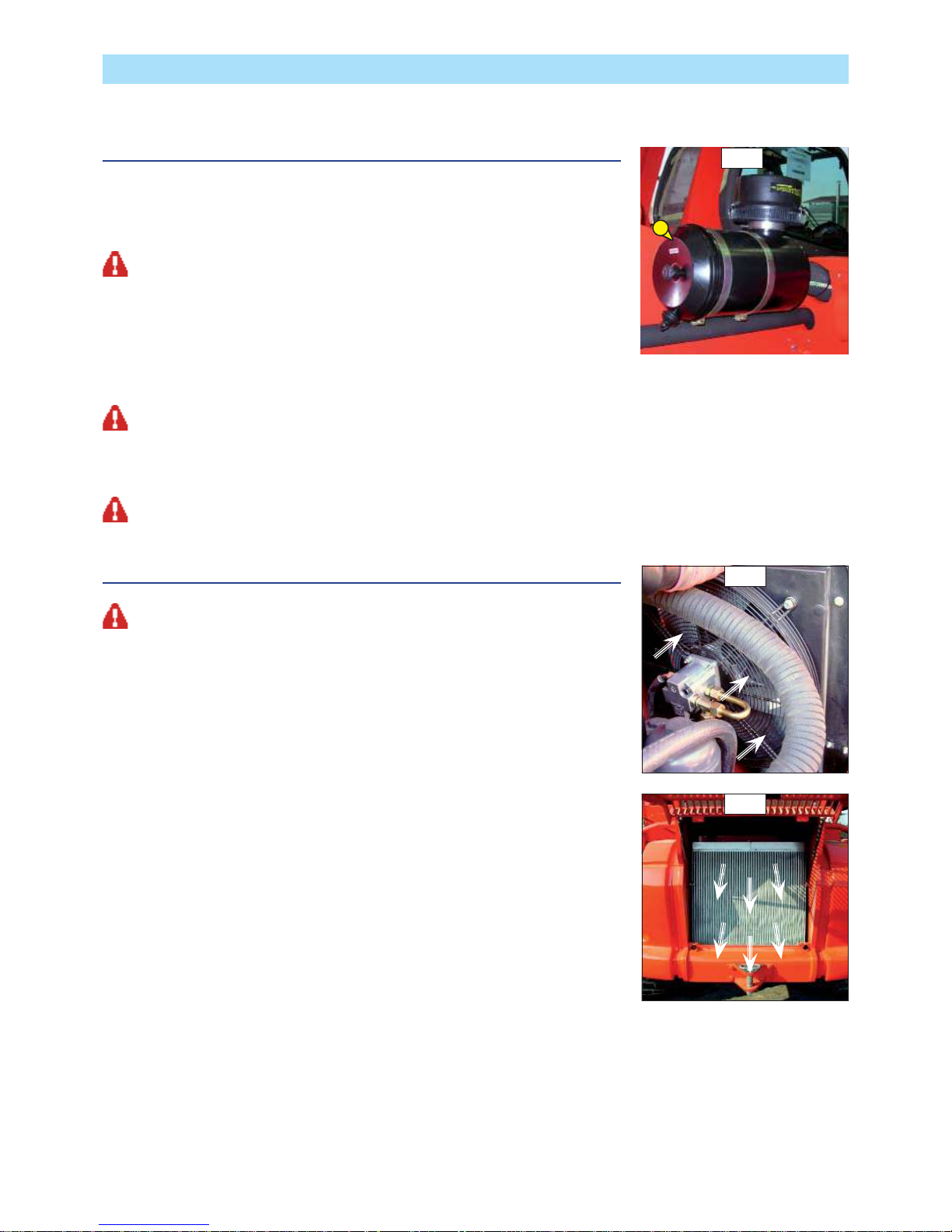
3-16
B - EVERY 50 HOURS SERVICE
Carry out the operations described previously as well as the following operations.
B1 - DRY AIR FILTER CARTRIDGE
CHECK - CLEAN
In case of use in a heavily dust laden atmosphere, there are pre-filtration cartridges (see: 3 MAINTENANCE: FILTERS CARTRIDGES AND BELTS). Also, the checking and cleaning periodicity
of the cartridge must be reduced.
If the clogging indicator light comes on, this operation must be carried out as quickly as possible (1 hour
maximum). The cartridge must not be cleaned more than seven times, after which the cartridge must be
changed. Never use the lift truck without an air filter or with a damaged air filter.
- For the disassembly and reassembly of the cartridge, see: 3 - MAINTENANCE: D3 - DRY AIR
FILTER CARTRIDGE.
- Clean the filter cartridge using a compressed air jet (max. pressure 3 bar) directed from the
top to the bottom and from the inside towards the outside at a minimum distance of 30 mm
from the cartridge wall.
- Cleaning is completed when there is no more dust on the cartridge.
Respect the safety distance of 30 mm between the air jet and the cartridge to avoid tearing or making a hole in the cartridge. The cartridge must not be blown
anywhere near the air filter box. Never clean the cartridge by tapping it against a hard surface. Your eyes must be protected during this intervention
.
- Clean the cartridge seal surfaces with a damp, clean lint-free cloth and grease with a silicone lubricant (MANITOU
reference: 479292).
- Check visually the outer condition of the air filter and its mounts. Verify the condition of the hoses and their mounts also.
Never clean the dry air filter cartridge by washing it in liquid. Do not clean by any means the safety cartridge located inside the filter cartridge, change it for
a new one if it is clogged or damaged.
B2 - RADIATOR CORES
CLEAN
The compressed air can cause accidents. While using compressed air, wear a protective device for the face
and protective clothing. The maximum pressure of the compressed air at the nozzle outlet must be 2 bar (30 PSI).
Check the radiator (water Fig. B2/1; oil Fig. B2/2)
for: damaged fins, corrosion, dirt, grease, insects, leaves, oil or other debris.
Direct the compressed air jets in the direction of the arrows.
Keep the air nozzle at a distance of about 6mm from the radiator fins.
Also use pressurized water to soften mud or solid debris.
The maximum water pressure must be less than 2.7 bar (40 PSI).
To remove oil and grease, use a degreaser and steam. Clean both sides of the radiator mass.
Wash the radiant mass with detergent and boiling water. Rinse the radiant mass thoroughly
with clean water.
After cleaning the radiator/s, start the I.C. engine, keeping it running at minimum for about
five minutes.
Bring the I.C. engine to maximum operating speed without load (this operation helps to remove
debris and to dry the radiant mass). Gradually reduce the I.C. engine speed to the minimum
and stop it.
Use a light to check behind the radiant mass to see if it is clean.
If necessary, clean again.
Check to see if fins are damaged. Bent fins can be straightened using a “comb”.
Check to make sure the following elements are in good condition. welded parts, mounting
brackets, piping, connections, clamps and gaskets.
Carry out repairs, if necessary.
B2/1
B2/2
B1
Page 97
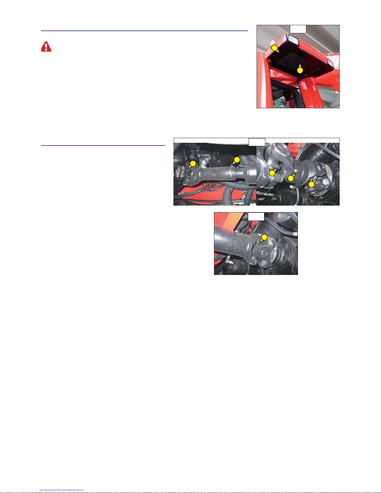
3-17
B3 - CONDENSER CORE (OPTION AIR CONDITIONING)
CHECK - CLEAN
In a polluting atmosphere, clean the radiator core every day. Do not use a water jet or high-pressure steam
as this could damage the condenser fins.
- Remove the protective grid 1 (fig. B3) and clean it if necessary.
- Visually check whether the condenser 2 (fig. B3) is clean and clean it if necessary.
- Clean the condenser using a compressed air jet aimed in the same direction as the air flow
(fig. B3).
NOTE: So as to enhance the cleaning, carry out this operation with the fans running.
B4 - TRANSMISSION UNIVERSAL JOINT
GREASE
- Clean and lubricate the following points with grease
(see: 3 - MAINTENANCE: LUBRICANTS AND FUEL) and
remove the surplus of grease.
1 - Lubricators of the universal joint Transmission/
Front axle (3 lubricators) (fig. B4/1).
2 - Lubricators of the universal joint Transmission/
Rear axle (3 lubricators) (fig. B4/2).
B3
2
1
B4/1
B4/2
1
1
2
1
1
1
Page 98
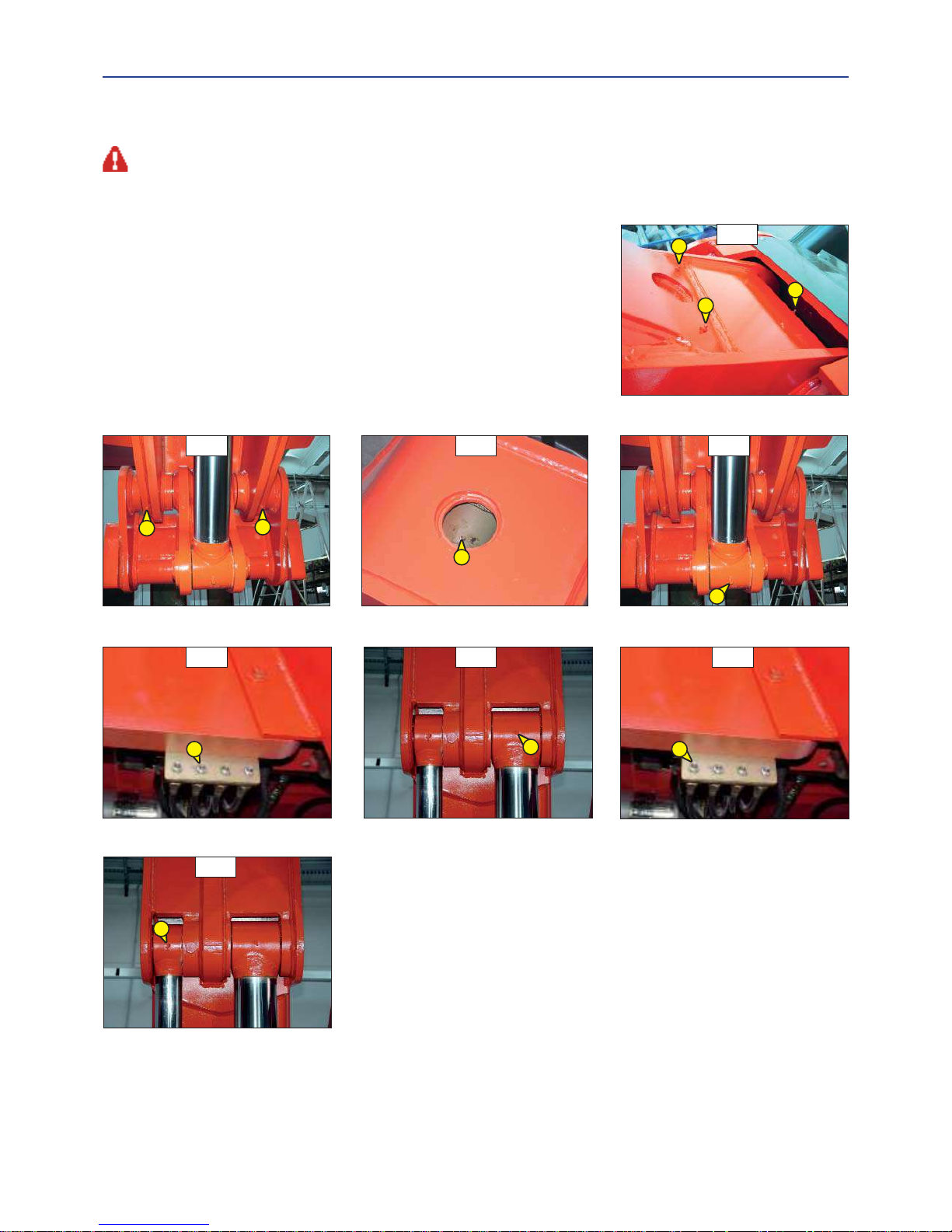
3-18
B5 - BOOM
GREASE
MHT 7140 T-E3
To be carried out weekly, if the lift truck has been operated for less than 50 hours during the week.
In the event of prolonged use in an extremely dusty or oxidising atmosphere, reduce this interval to 10 working hours or every day.
- Clean and lubricate the following points with grease (see: 3 - MAINTENANCE: LUBRICANTS AND FUEL) and remove the surplus of grease.
1 - Lubricators of the boom axle (2 lubricators) (fig. B5/1).
2 - Lubricators of the carriage axle (2 lubricators) (fig. B5/2).
3 - Lubricator of the tilt cylinder foot axle (1 lubricator) (fig. B5/3).
4 - Lubricator of the tilt cylinder head axle (1 lubricator) (fig. B5/4).
5 - Lubricator of the lifting cylinder foot axle (1 lubricator) (fig. B5/5).
6 - Lubricator of the lifting cylinder head axle (1 lubricator) (fig. B5/6).
7 - Lubricator of the compensation cylinder foot axle (1 lubricator) (fig. B5/67).
8 - Lubricator of the compensation cylinder head axle (1 lubricator) (fig. B5/8).
B5/1
1
B5/2
2
B5/4
4
B5/6
6
B5/7
7
B5/3
B5/5
5
B5/8
3
2
8
1
1
Page 99

3-19
B5 - BOOM
GREASE
MHT 10180 LT-E3
To be carried out weekly, if the lift truck has been operated for less than 50 hours during the week.
In the event of prolonged use in an extremely dusty or oxidising atmosphere, reduce this interval to 10 working hours or every day.
- Clean and lubricate the following points with grease (see: 3 - MAINTENANCE: LUBRICANTS AND FUEL) and remove the surplus of grease.
1 - Lubricators of the boom axle (2 lubricators) (fig. B5/1).
2 - Lubricators of the carriage axle (2 lubricators) (fig. B5/2).
3 - Lubricator of the tilt cylinder foot axle (1 lubricator) (fig. B5/3).
4 - Lubricator of the tilt cylinder head axle (1 lubricator) (fig. B5/4).
5 - Lubricator of the lifting cylinder foot axle (1 lubricator) (fig. B5/5).
6 - Lubricator of the lifting cylinder head axle (1 lubricator) (fig. B5/6).
7 - Lubricator of the compensation cylinder foot axle (1 lubricator) (fig. B5/67).
8 - Lubricator of the compensation cylinder head axle (1 lubricator) (fig. B5/8).
B5/4
4
B5/3
3
2
2
B5/2
B5/1
1
1
1
B5/6
B5/7
B5/5
B5/8
6
7
5
8
Page 100
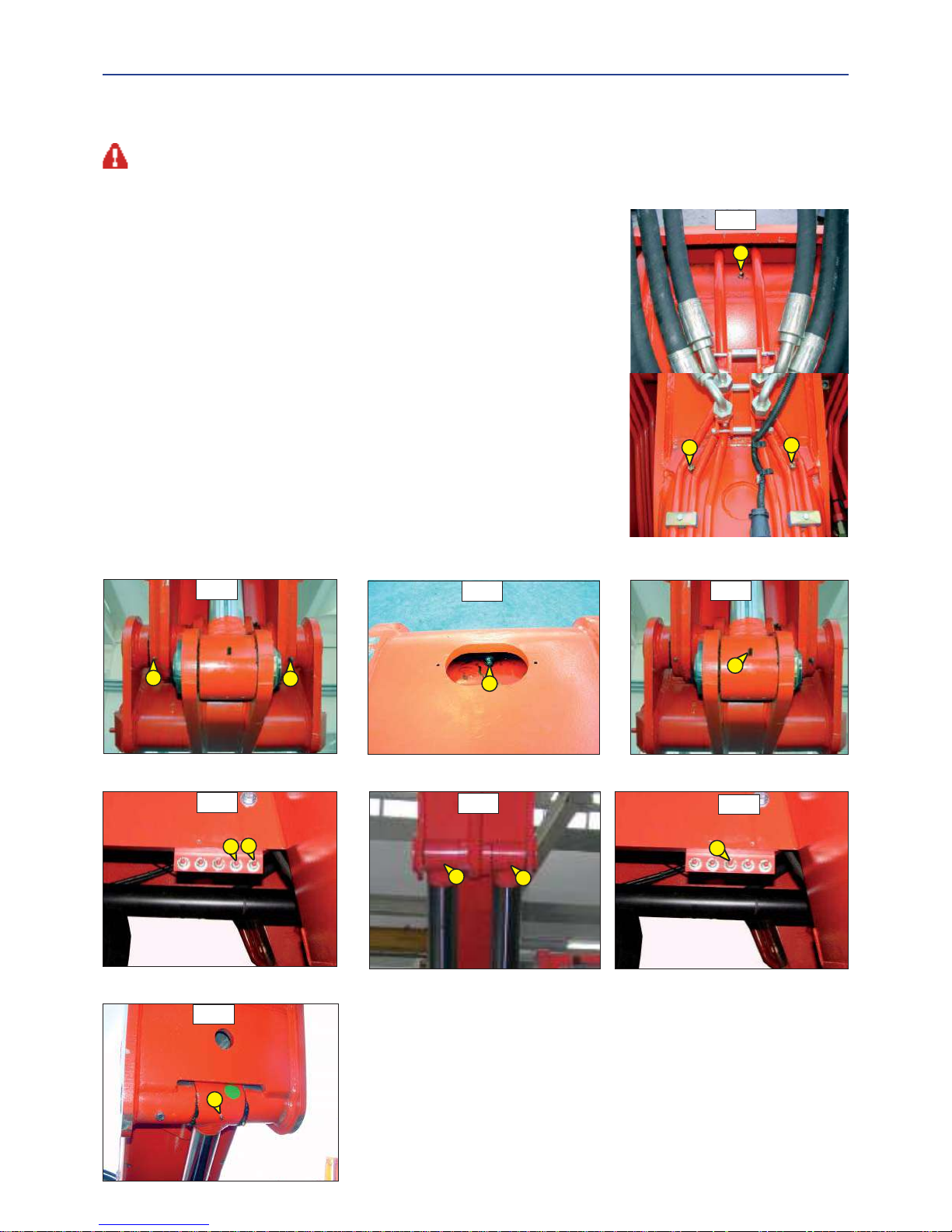
3-20
B5 - BOOM
GREASE
MHT 10225 LT-E3
To be carried out weekly, if the lift truck has been operated for less than 50 hours during the week.
In the event of prolonged use in an extremely dusty or oxidising atmosphere, reduce this interval to 10 working hours or every day.
- Clean and lubricate the following points with grease (see: 3 - MAINTENANCE: LUBRICANTS AND FUEL) and remove the surplus of grease.
1 - Lubricators of the boom axle (2 lubricators) (fig. B5/1).
2 - Lubricators of the carriage axle (2 lubricators) (fig. B5/2).
3 - Lubricator of the tilt cylinder foot axle (1 lubricator) (fig. B5/3).
4 - Lubricator of the tilt cylinder head axle (1 lubricator) (fig. B5/4).
5 - Lubricator of the lifting cylinder foot axle (1 lubricator) (fig. B5/5).
6 - Lubricator of the lifting cylinder head axle (1 lubricator) (fig. B5/6).
7 - Lubricator of the compensation cylinder foot axle (1 lubricator) (fig. B5/67).
8 - Lubricator of the compensation cylinder head axle (1 lubricator) (fig. B5/8).
B5/4
4
B5/3
3
2
2
B5/2
B5/1
1
1
1
B5/6
B5/7
B5/5
B5/8
6
7
5
8
5
6
 Loading...