

Manitou MHT 10225 Repair Manual
MANITOU BF
Head o ce: 430, Rue de l’Aubinière
44150 Ancenis - FRANCE
Share capital: 39,548,949 euros
857 802 508 RCS Nantes
Tel: +33 (0)2 40 09 10 11
www.manitou.com
REPAIR MANUAL
MANUEL DE RÉPARATION
REPARATURANLEITUNG
MANUAL DE REPARACIÓN
MANUALE RIPARAZIONE
This document has been printed from
e doc
my

La présente brochure n’est fournie qu’à titre consultatif, toute reproduction, copie, représentation, captation, cession, distribution, ou
autre, partiellement ou en totalité, sous quelque format que ce soit est interdite. Les schémas, les dessins, les vues, les commentaires
les indications, l’organisation même du document qui sont rapportés dans la présente documentation, sont la propriété intellectuelle
de MANITOU BF. Toute infraction à ce qui précède est susceptible d’entraîner des condamnations civiles et pénales. Les logos ainsi que
l’identité visuelle de l’entreprise sont la propriété de MANITOU BF et ne peuvent être utilisés sans autorisation exprès et formelle. Tous
droits réservés.
This manual is for information purposes only. Any reproduction, copy, representation, recording, transfer, distribution, or other, in part
or in whole, in any format is prohibited. The plans, designs, views, commentaries and instructions, even the document organization
that are found in this document, are the intellectual property of MANITOU BF. Anyviolation of the aforementioned may lead to civil
and criminal prosecution. The logos as well as the visual identity of the company are the property of MANITOU BF and may not be used
without express and formal authorization. All rights are reserved.
Die vorliegende Broschüre dient allein zur Beratung. Nachdruck, Fotokopieren, Vervielfältigung, Darstellung, Erfassung,
Überlassung, Verbreitung oder Sonstiges (ganz oder teilweise) in jeglicher Form sind verboten. Die Entwürfe, Zeichnungen,
Bilder, Darstellungen, Ansichten, Kommentare, Hinweise und der Aufbau der Druckschrift selbst, die in der vorliegenden
Dokumentation enthalten sind, sind geistiges Eigentum von MANITOU BF. Alle Verstöße gegen das Vorstehende können zu strafoder zivilrechtlicher Verfolgung führen. Die Logos und Markenzeichen sowie Unternehmens- und Produktbezeichnungen sind
Eigentum von MANITOU BF und dürfen ohne ausdrückliche Genehmigung nicht verwendet werden. Alle Rechte vorbehalten.
Este folleto se ofrece a título meramente informativo y queda prohibida su reproducción, copia, representación, captación, cesión,
distribución y demás, parcial o total, en el formato que sea. Los esquemas, dibujos, vistas, comentarios, indicaciones, la organización
misma del documento aportado en esta documentación son propiedad intelectual de MANITOU BF. Cualquier infracción a lo
antedicho puede acarrear condenas civiles y penales. Los logotipos y la identidad visual de la empresa son propiedad de MANITOU
BF y no pueden utilizarse sin su autorización expresa y formaL. Reservados todos los derechos.
Il presente manuale è fornito esclusivamente a titolo di consultazione; è vietata qualsiasi riproduzione, copia, rappresentazione,
acquisizione, cessione, distribuzione o altro, parziale o totale, e in qualsivoglia formato. Gli schemi, i disegni, le viste, i commenti,
le indicazioni e l’organizzazione stessa del documento, riportati nella presente documentazione, sono proprietà intellettuale
di MANITOU BF. Qualsiasi violazione a quanto riportato sopra è passibile di condanna civile e penale. I loghi e l’identità visiva
dell’azienda sono di proprietà di MANITOU BF e non possono essere utilizzati senza previa autorizzazione espressa e formale. Tutti i
diritti sono riservati.

GENERAL INSTRUCTIONS AND SAFETY NOTICE
Group 00 (General characteristics and safety) 1-1
ENGINE
Groupe 10 (Engine) 2-1
OPTIONS - ACCESSORIES
Groupe 110 (Options - Attachments) 3-1
TRANSMISSION
Groupe 20 (Transmission) 4-1
BRAKE
Groupe 40 (Brake) 5-1
TELESCOPIC BOOM
Groupe 50 (Boom) 6-1
HYDRAULIC
Groupe 70 (Hydraulic) 7-1
ELECTRICITY
Groupe 80 (Electricity) 8-1
DRIVER CAB
Groupe 85 (Driver s cab) 9-1

- GENERAL INSTRUCTIONS AND SAFETY
NOTICE
- GENERAL CONTROL AND ADJUSTMENT
GENERAL
00

00-00-M184EN
GENERAL INSTRUCTIONS AND SAFETY NOTICE
pages
PREAMBLE . . . . . . . . . . . . . . . . . . . . . . . . . . . . . . . . . . . . . . . . . . . . . . . . . . . . . . . . . . . . . . . . . . . . . . . .2
MAINTENANCE POSITION . . . . . . . . . . . . . . . . . . . . . . . . . . . . . . . . . . . . . . . . . . . . . . . . . . . . . . . . .3
RULES FOR MAINTENANCE . . . . . . . . . . . . . . . . . . . . . . . . . . . . . . . . . . . . . . . . . . . . . . . . . . . . . . . .4
(05/06/2012)
00
00-00-M184EN
GENERAL INSTRUCTIONS AND SAFETY NOTICE
This chapter deals with the general instructions and safety notice during inspection and maintenance
work.
Other instructions and warnings are indicated in each chapter concerned.
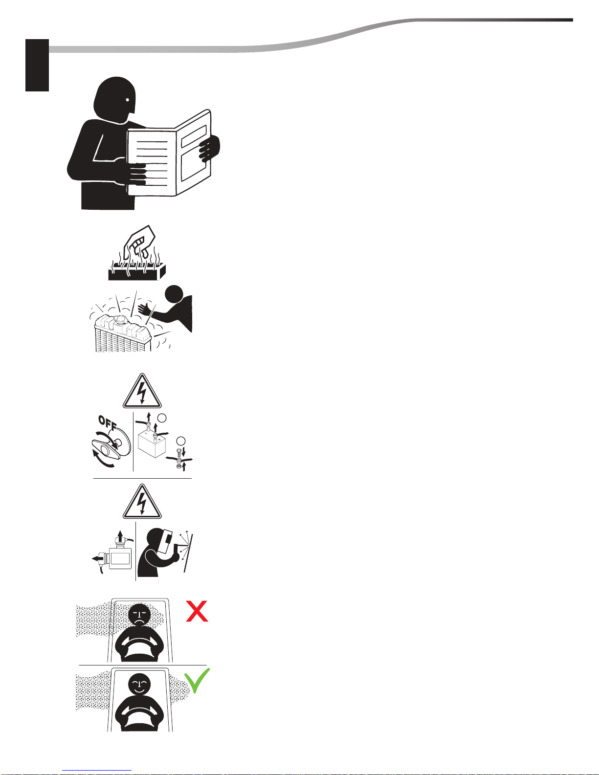
In order to reduce accident risks, make sure to:
– Follow the instructions in the truck operating and maintenance manual.
This manual should be found in all trucks.
– Please follow all safety instructions.
– Use the appropriate tools for any work to be performed.
– Use original Manitou spare parts.
Any non-compliance increases the risk of accidents occurring which may lead to causing grievous bodily
harm and even death.
An e cient, dependable and pro table combination will be formed if the operator follows the safety
manual correctly and the machine is serviced properly.
When you see this symbol:
It means: Warning! Be careful! Your safety, somebody else’s or the safety of the lift truck itself
is at risk.
The manufacturer cannot predict all possible risky situations. Consequently, the safety instructions
given in the safety manual are not exhaustive.
At any time, as an operator, you must envisage, within reason, the possible risk to yourself, to others or
to the lift truck itself when you repair, service or drive it.
Manitou cannot be held responsible for the use of any lifting devices, tools or operating methods other
than those speci ed.
PREAMBLE
(05/06/2012)
00
2
00
00-00-M184EN
GENERAL INSTRUCTIONS AND SAFETY NOTICE
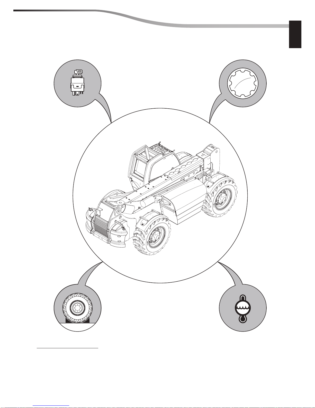
Before any intervention:
1 - Place the machine on a at surface and chock the wheels.
2 - Turn o the engine and remove the ignition key.
3 - Let the machine cool down.
4 - Take all the pressure out of the circuits concerned.
MAINTENANCE POSITION
(05/06/2012)
00
3
00
1
3
4
2
00-00-M184EN
GENERAL INSTRUCTIONS AND SAFETY NOTICE
RULES FOR MAINTENANCE
Do not carry out any work on the machine unless you have followed
a suitable training course and have the knowledge required for it.
Make sure you have taken into consideration all the indicator plates
on the machine and in the instruction manual.
Be careful not to burn yourself when touching hot liquids or parts
when operations have to be done before the machine has had
time to cool down.
Before carrying out any operation on an electrically powered
component, activate the battery cut-o .
If the telehandler does not have a battery isolating switch, disconnect
the battery terminals then gather them.
b
Before carrying out any welding operations, think of
disconnecting computers.
A machine operating in a contaminated environment should be
specifically equipped. Moreover, local safety notices deal with
maintenance and repair work on such machines.
(05/06/2012)
00
4
00
ECU
2
1
00-00-M184EN
GENERAL INSTRUCTIONS AND SAFETY NOTICE
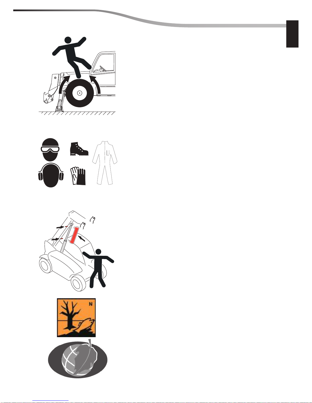
Never step on a part of the machine that has not been designed for it.
Never wear clothes, jewelry or objects that could get caught during
work and cause accidents.
Always wear protection glasses, gloves, safety shoes as well as any
other protection required for the work to be carried out.
When carrying out maintenance operations near a mobile object,
make sure it is securitized.
When changing, or draining oils or fuel, or any other operation with
liquids, solids, gases that are harmful to the environment, make
sure the necessary precautions are taken to avoid contaminating
the environment.
(05/06/2012)
00
5
00
00-00-M184EN
GENERAL INSTRUCTIONS AND SAFETY NOTICE
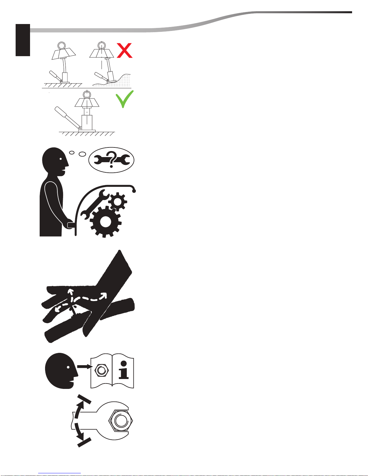
When lifting or shoring a component of the machine, make sure
the equipment used is suitable for at least the load for which it
is subjected by the component and that it meets the national
standards for lifting devices.
When using a jack, make sure it is used on a at, uniform surface, is
sturdy enough to support the load, that its lifting capacity is su cient
and that it is correctly placed and positioned under the machine.
Make sure no object or tool which could cause an accident is left
in the machine.
Never control any leaks using a hand.
Never adjust a component to over the maximum capacity indicated
by the manufacturer.
(05/06/2012)
00
6
00
max.
min.
MIN
MAX

00-04-M184EN
GENERAL CONTROL AND ADJUSTMENT
pages
STANDARD TIGHTENING TORQUES . . . . . . . . . . . . . . . . . . . . . . . . . . . . . . . . . . . . . . . . . . . . . . . .2
(05/06/2012)
00
00-04-M184EN
GENERAL CONTROL AND ADJUSTMENT
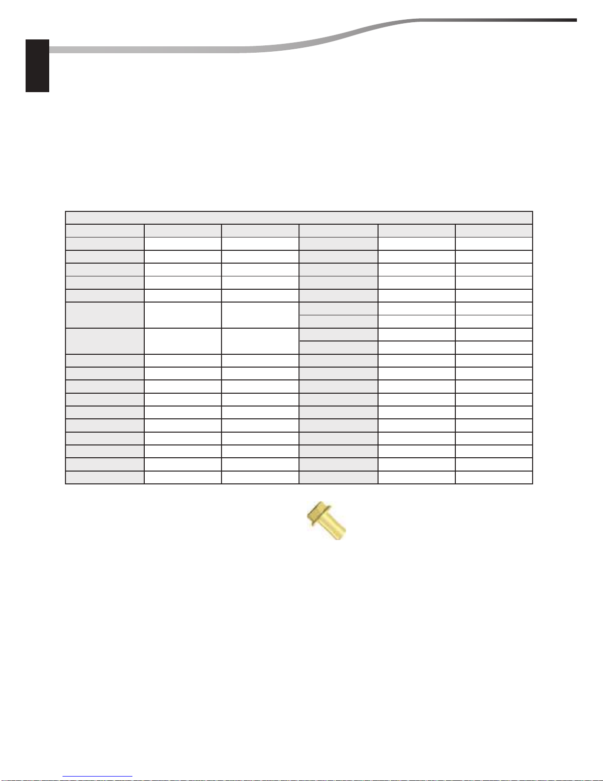
STANDARD TIGHTENING TORQUES
Standard tightening torque to be used when not otherwise indicated in the removal and re tting
operations:
- The following tightening torques are given for hexagon head screws without flanges and
cylinder head hexagon socket screws.
- The torques are given for a friction coe cient μ = 0,20 corresponding to dry- tted zinc-plated
fasteners and for torque tools having a ± 20 % class C tightening torque accuracy (equivalent
to pneumatic screwdrivers).
NF E 25-030-1 Screw / Nut connection :
Tightening torque in N•m (±20%)
Ø x “coarse” pitch Grade 8.8 Grade 10.9 Ø x “ ne” pitch Grade 8.8 Grade 10.9
M3 x 0,5 1 1,5 - - -
M4 x 0,7 2,4 3,5 - - -
M5 x 0,8 4,8 7,1 - - -
M6 x 1 8,2 12,1 - - -
M8 x 1,25 20 30 M8 x 1 22 32
M10 x 1,5 40 59
M10 x 1,25 43 63
M10 x 1 46 68
M12 x 1,75 69 102
M12 x 1,5 74 108
M12 x 1,25 78 115
M14 x 2 111 163 M14 x 1,5 123 181
M16 x 2 175 256 M16 x 1,5 190 279
M18 x 2,5 240 352 M18 x 1,5 279 410
M20 x 2,5 341 501 M20 x 1,5 391 574
M22 x 2,5 470 691 M22 x 1,5 531 780
M24 x 3 588 864 M24 x 2 659 967
M27 x 3 874 1284 M27 x 2 965 1418
M30 x 3,5 1181 1735 M30 x 2 1351 1984
M33 x 3,5 1614 2371 M33 x 2 1821 2674
M36 x 4 2068 3037 - - -
b
For hexagon screws with anges:
Apply an increased torque of +10%.
(Standard NF E 25-030-1)
bWhere washers are used, the following coe cient is to be applied (FD E 25-502) :
- Smooth tapered washer (CL): +5%
- Spring (or Grower) washer without jaws (W) : +10%
- Conical, internal teeth (CDJ-JZC) : +15%
(05/06/2012)
00
2
00
ENGINE
- ENGINE COMPONENTS LOCATION
- ENGINE CONTROL AND ADJUSTMENT
- ENGINE REMOVAL
- ENGINE REFIT
- ENGINE CHARACTERISTICS AND
SPECIFICATIONS
- ENGINE CONTROL AND ADJUSTMENT
10
647370EN
(ENGINE OM 904 LA
120-150-175-CV EURO 3 )
M
R

(05/06/2012) 10-03-M184EN
10
ENGINE COMPONENTS LOCATION
page
MERCEDES ENGINE. . . . . . . . . . . . . . . . . . . . . . . . . . . . . . . . . . . . . . . . . . . . . . . . . . . . . . . . . .2
(05/06/2012)10-03-M184EN
10
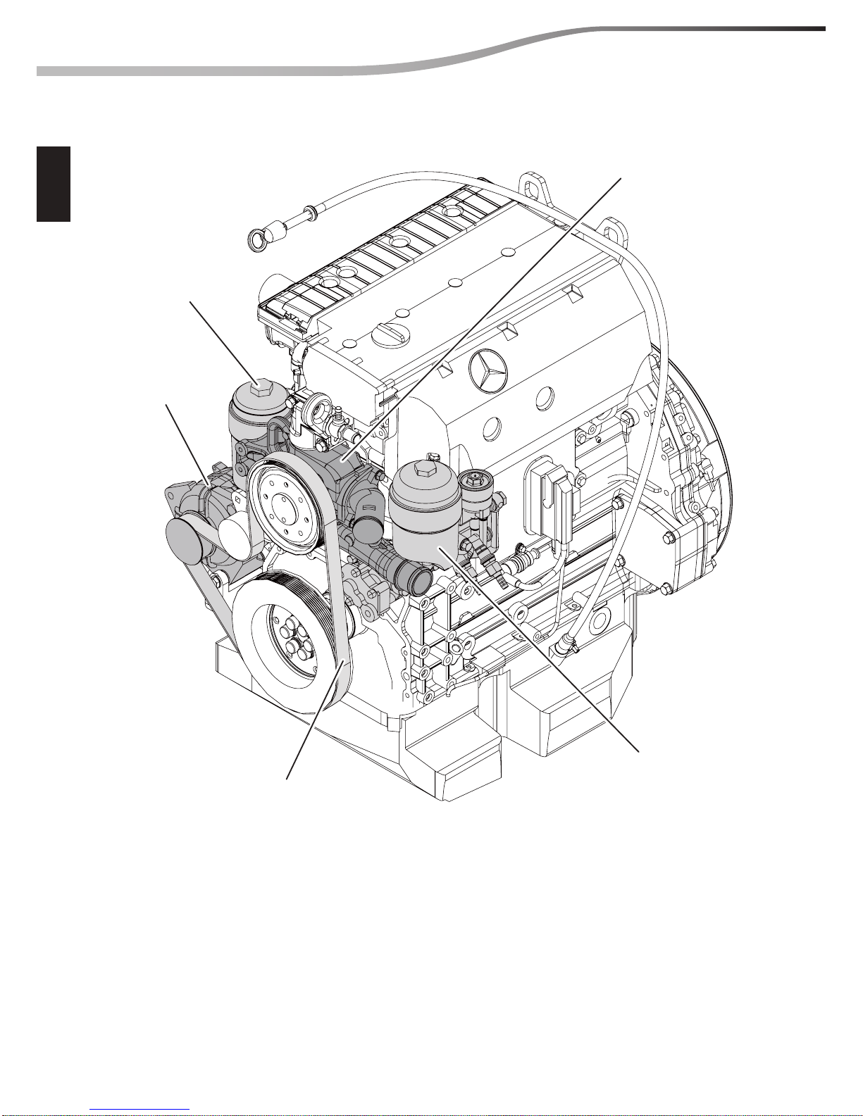
2 ENGINE COMPONENTS LOCATION
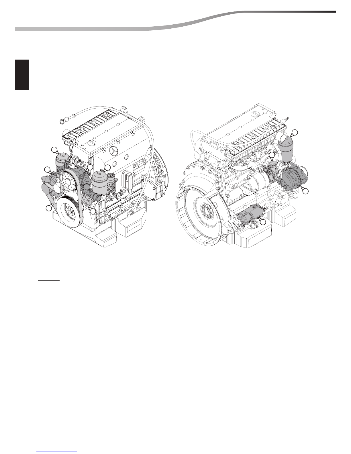
MERCEDES ENGINE
Oil lter
Alternator
Belt
Fuel pump
and lter
Engine cooling
water pump
(05/06/2012) 10-03-M184EN
10
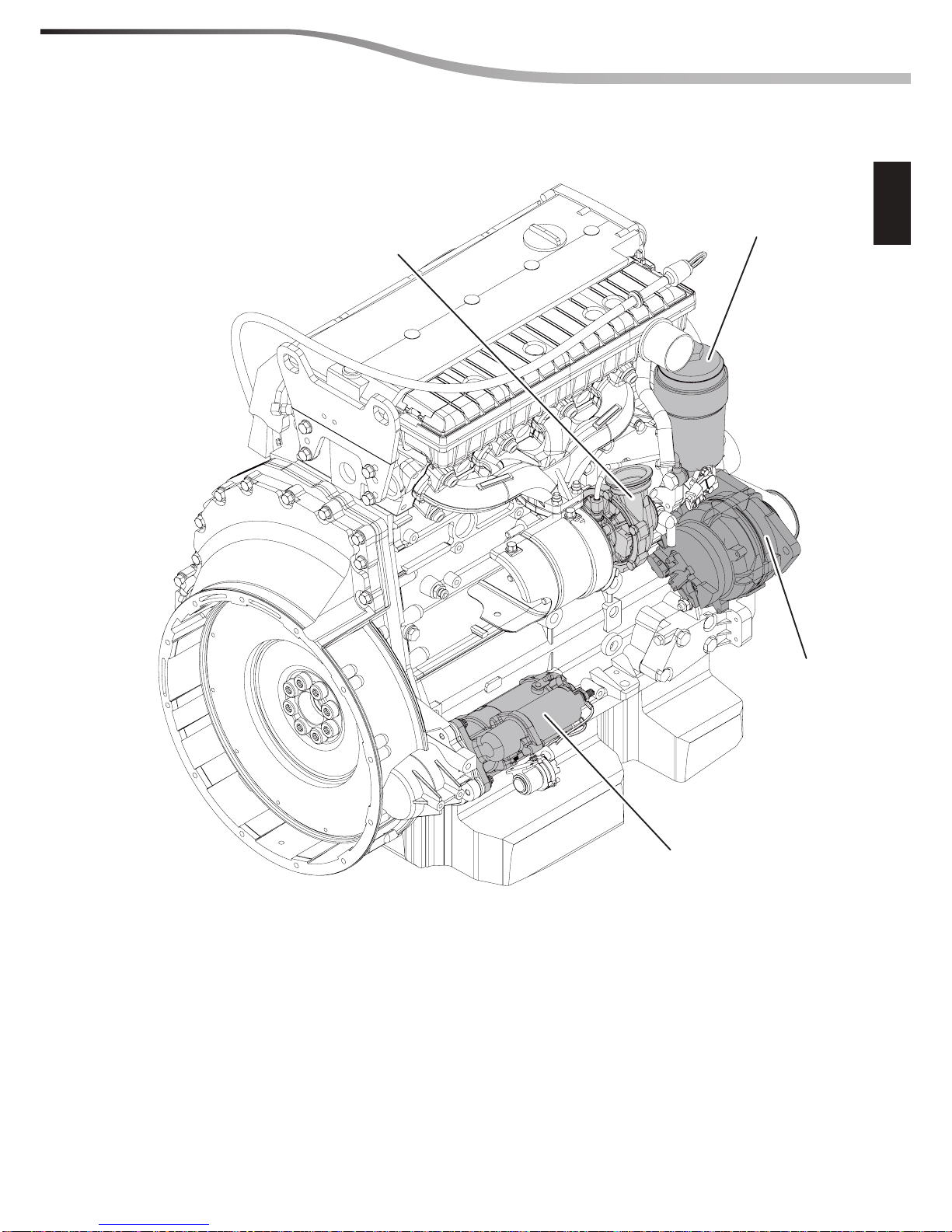
3ENGINE COMPONENTS LOCATION
Turbocompressor
Oil lter
Alternator
Starter
motor

(05/06/2012)10-03-M184EN
10
4 ENGINE COMPONENTS LOCATION

(02/08/2012) 10-04-M184EN
10
ENGINE CONTROL AND ADJUSTMENT
page
ENGINE TIGHTENING TORQUE . . . . . . . . . . . . . . . . . . . . . . . . . . . . . . . . . . . . . . . . . . . . . . . . . . . . .2
– ASSEMBLING THE ENGINE . . . . . . . . . . . . . . . . . . . . . . . . . . . . . . . . . . . . . . . . . . . . . . . . . . . . . . . 2
– FUEL CIRCUIT. . . . . . . . . . . . . . . . . . . . . . . . . . . . . . . . . . . . . . . . . . . . . . . . . . . . . . . . . . . . . . . . . . . . 2
(02/08/2012)10-04-M184EN
10
2 ENGINE CONTROL AND ADJUSTMENT
ENGINE TIGHTENING TORQUE
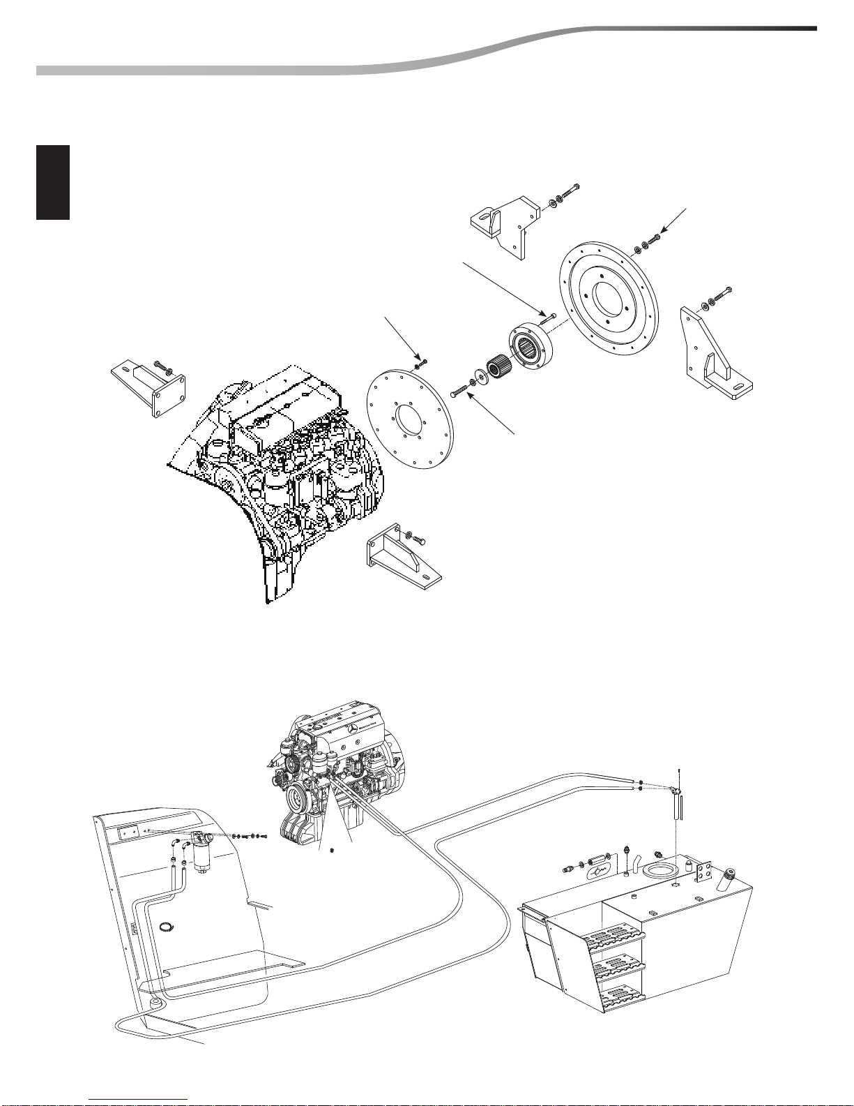
ASSEMBLING THE ENGINE
FUEL CIRCUIT
25 Nm
+ apply “Loctite 243”
45 Nm
+ apply “Loctite 243”
45 Nm
+ apply “Loctite 243”
210 Nm
+ apply “Loctite 243”
(05/06/2012) 10-06-M184EN
10
ENGINE REMOVAL
page
REMOVING THE ENGINE COMPONENTS . . . . . . . . . . . . . . . . . . . . . . . . . . . . . . . . . . . . . .2
PREPARATION AND SAFETY INSTRUCTIONS. . . . . . . . . . . . . . . . . . . . . . . . . . . . . . . . . .2
A REMOVING THE ALTERNATOR BELT. . . . . . . . . . . . . . . . . . . . . . . . . . . . . . . . . . . . . . . . . . . 3
B REMOVING THE ALTERNATOR . . . . . . . . . . . . . . . . . . . . . . . . . . . . . . . . . . . . . . . . . . . . . . . . 4
C REMOVING THE STARTER MOTOR. . . . . . . . . . . . . . . . . . . . . . . . . . . . . . . . . . . . . . . . . . . . . 6
D REMOVING THE OIL FILTER . . . . . . . . . . . . . . . . . . . . . . . . . . . . . . . . . . . . . . . . . . . . . . . . . . . 7
E REMOVING THE FUEL OIL FILTER AND PUMP. . . . . . . . . . . . . . . . . . . . . . . . . . . . . . . . . . 8
F REMOVING THE ENGINE COOLING WATER PUMP . . . . . . . . . . . . . . . . . . . . . . . . . . . . . 9
G REMOVING THE TURBOCOMPRESSOR . . . . . . . . . . . . . . . . . . . . . . . . . . . . . . . . . . . . . . . . 12
REMOVING THE ENGINE . . . . . . . . . . . . . . . . . . . . . . . . . . . . . . . . . . . . . . . . . . . . . . . . . . . . .16
DISASSEMBLY ORDER. . . . . . . . . . . . . . . . . . . . . . . . . . . . . . . . . . . . . . . . . . . . . . . . . . . . . . . . . . . . 16
REMOVING THE RADIATOR MOTOR . . . . . . . . . . . . . . . . . . . . . . . . . . . . . . . . . . . . . . . . . . . . . . 17
REMOVING THE RADIATOR . . . . . . . . . . . . . . . . . . . . . . . . . . . . . . . . . . . . . . . . . . . . . . . . . . . . . . 19
REMOVING THE ENGINE . . . . . . . . . . . . . . . . . . . . . . . . . . . . . . . . . . . . . . . . . . . . . . . . . . . . . . . . . 21
(05/06/2012)10-06-M184EN
10
2 ENGINE REMOVAL
1
5
6
3
4
7
5
1
8
2
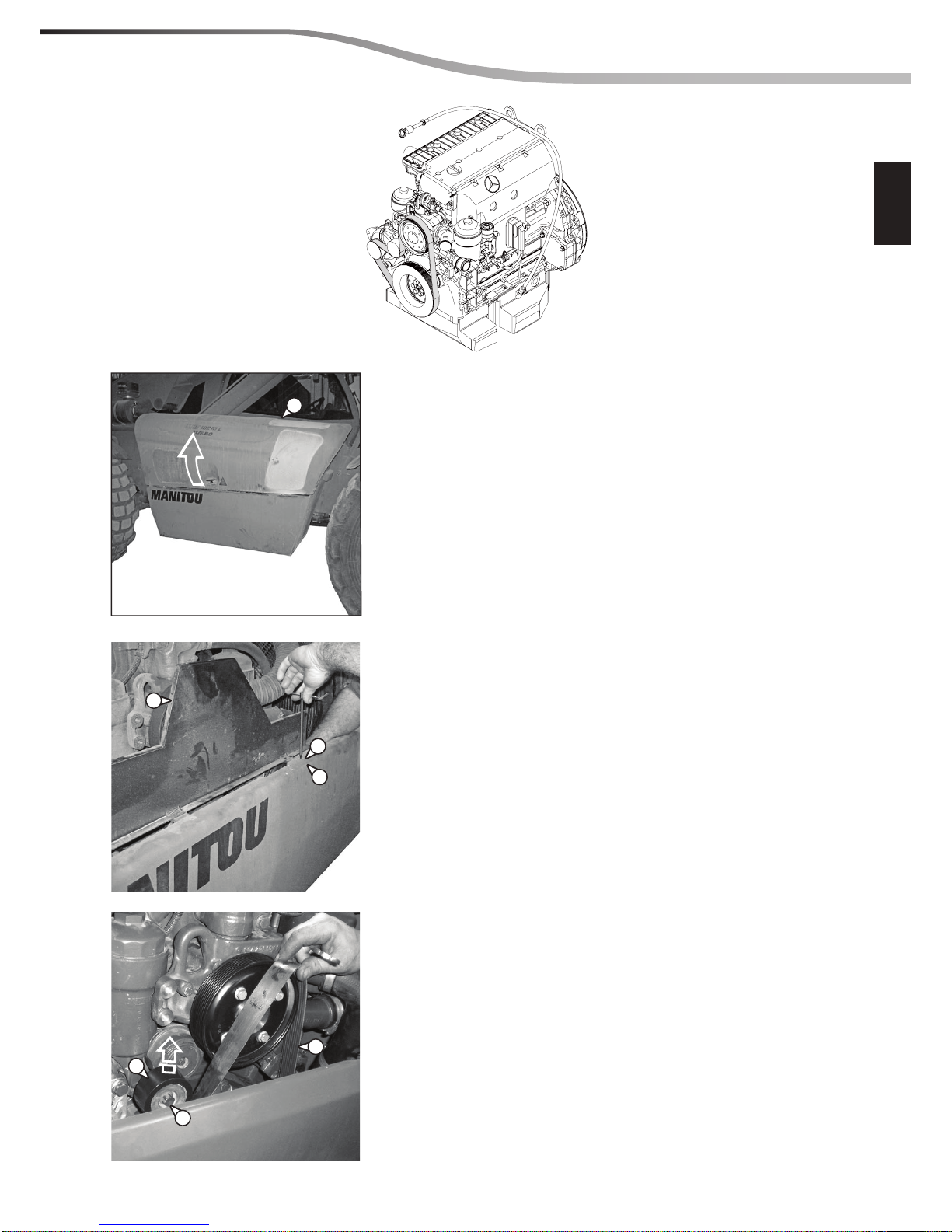
REMOVING THE ENGINE COMPONENTS
Legend:
1 - Alternator
2 - Starter motor
3 - Alternator belt
4 - Fuel lter
5 - Oil lter
6 - Engine cooling water pump
7 - Fuel pump
8 - Turbocompressor
PREPARATION AND SAFETY INSTRUCTIONS
Deactivate the ignition key and disconnect the negative pole from the battery.
(05/06/2012) 10-06-M184EN
10
3ENGINE REMOVAL
A - REMOVING THE ALTERNATOR BELT
Open the hood (Ref. 1) of the engine compartment.
Remove the guard (Ref. 2) after unscrewing the screws (Ref. 3)
and the nuts (Ref. 4).
Insert an unlocking lever on the screw (Ref. 5), tilt the belt
tensioner roller upwards (Ref. 6) and remove the belt (Ref. 7).
1
3
5
7
6
2
4
(05/06/2012)10-06-M184EN
10
4 ENGINE REMOVAL
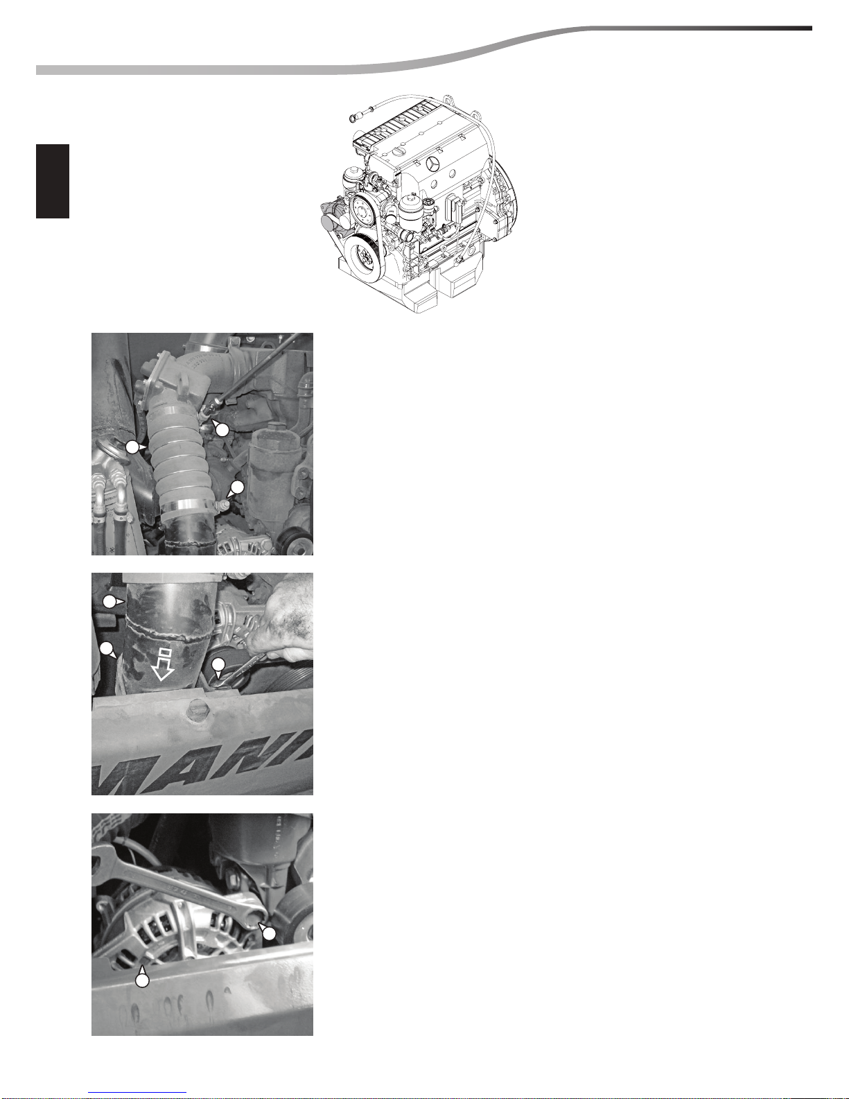
B - REMOVING THE ALTERNATOR
Carry out operation A.
Slacken the clamps (Ref. 1) and remove the hose (Ref. 2) positioned
on the air cooling radiator tube.
Slacken the screws (Ref. 3) and remove the bracket (Ref. 4) which
supports the air cooling radiator tube (Ref. 5), move the tube
downwards to make it easier to access the alternator.
Slacken the screws (Ref. 6) which secure the alternator (Ref. 7)
to the engine.
6
3
5
4
2
1
1
7
(05/06/2012) 10-06-M184EN
10
5ENGINE REMOVAL
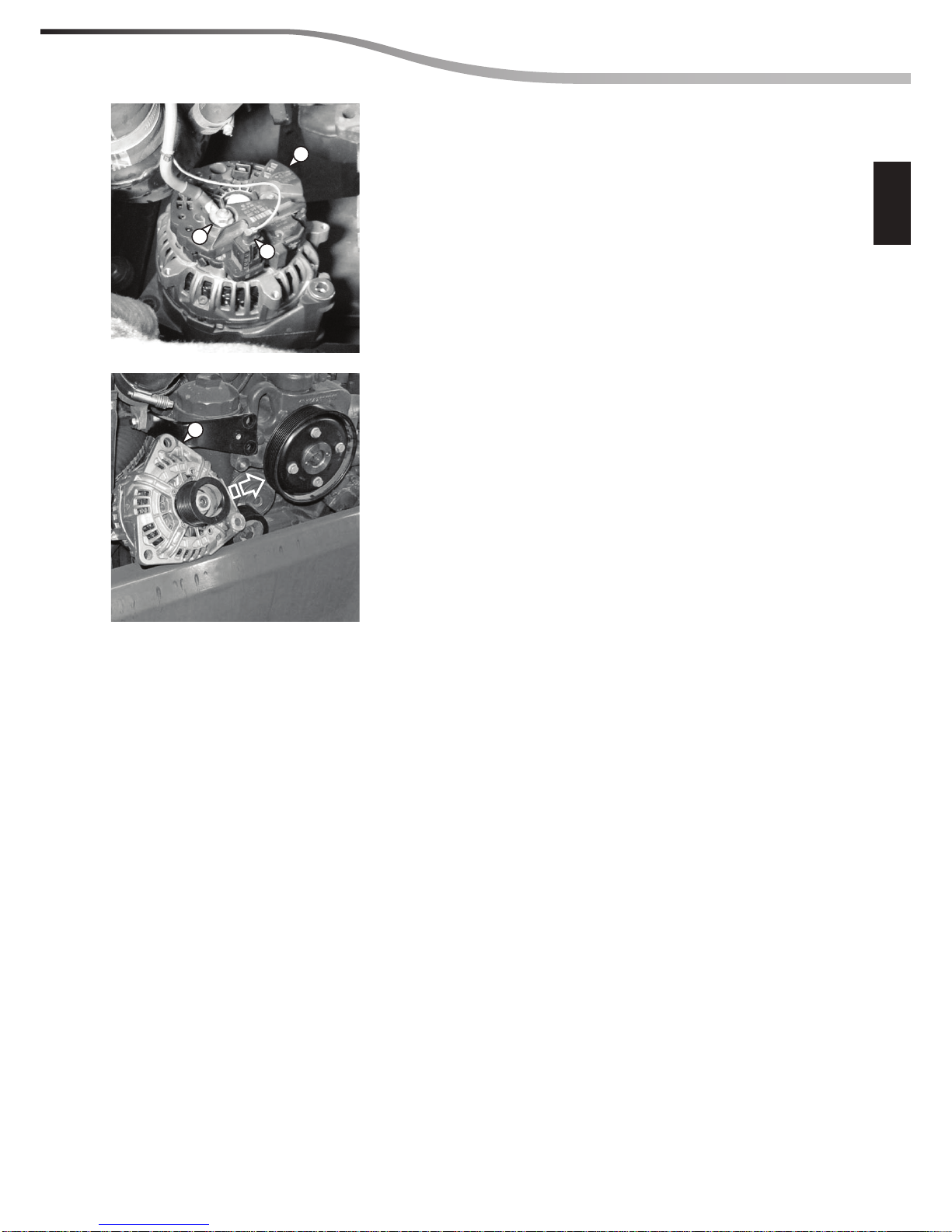
Disconnect the electric wires (Ref. 8 and 9) for connection to
the alternator (Ref. 7).
The alternator can now be removed (Ref. 7) from the engine.
8
9
7
7
(05/06/2012)10-06-M184EN
10
6 ENGINE REMOVAL
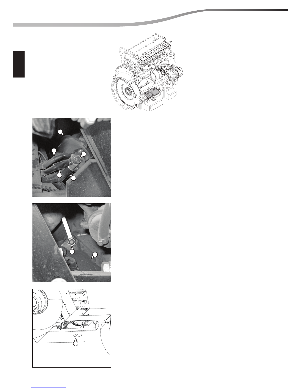
C - REMOVING THE STARTER MOTOR
Slacken the nut (Ref. 1) and remove the electric wires (Ref. 2-3-4)
for the starter motor connection (Ref. 5)
Slacken the screws (Ref. 6) and remove the starter motor
(Ref. 5) from the engine base.
Remove the starter motor (Ref. 5) from the slot (Ref.f) under the
engine compartment.
5
5
4
1
2
3
6
7
(05/06/2012) 10-06-M184EN
10
7ENGINE REMOVAL
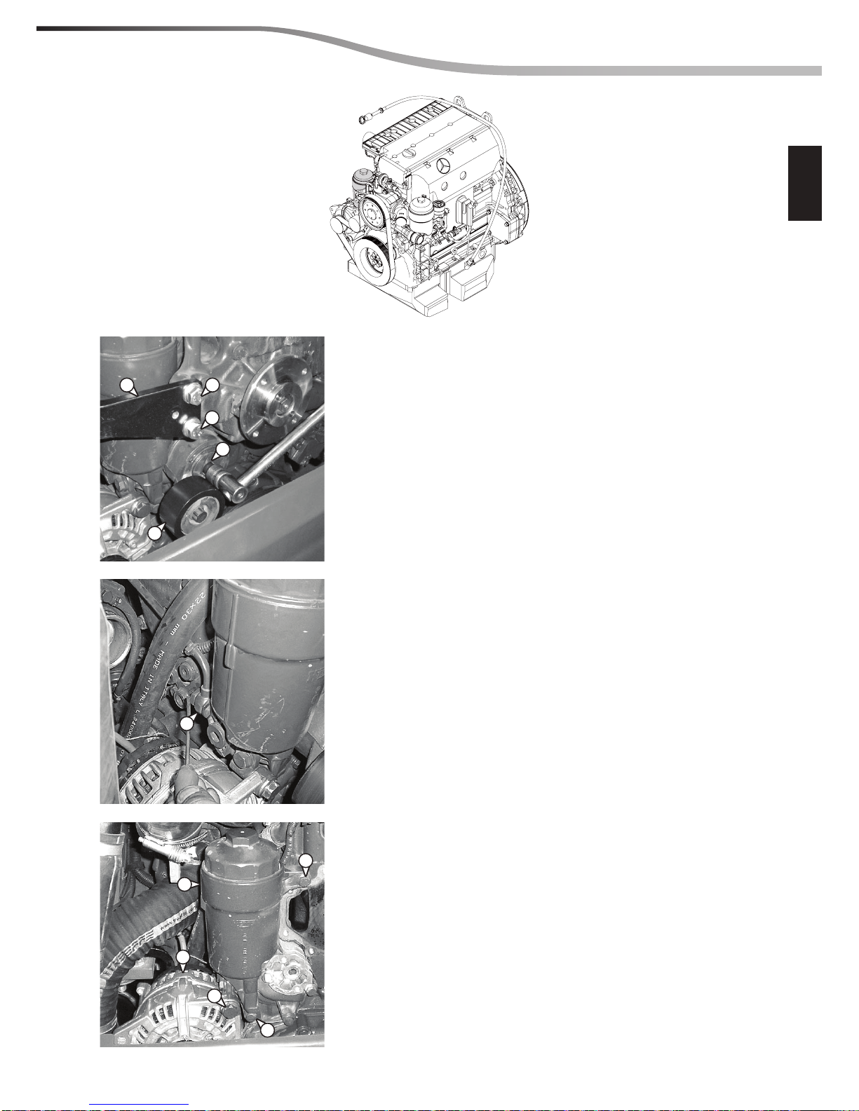
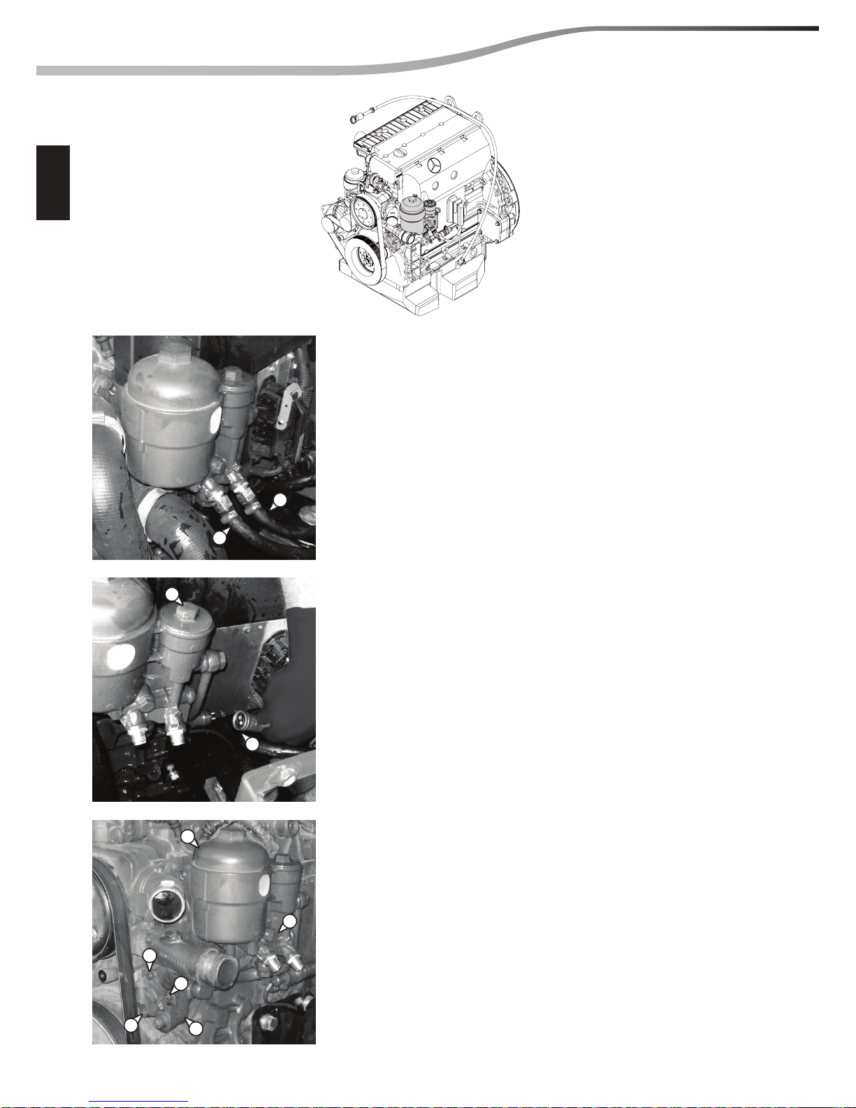
D - REMOVING THE OIL FILTER
Carry out operation B.
Slacken the screw (Ref. 1) and remove the belt tensioner (Ref. 2).
Slacken the screws (Ref. 3) and remove the bracket (Ref. 4).
Disconnect the oil inlet pipe (Ref. 5) .
Fix the pipe using a clamp so that it does not slip in the bottom
part of the engine housing and oil does not leak out.
Slacken the screw (Ref. 6) to free the alternator (Ref. 7) and rotate
it downwards.
Slacken the screws (Ref. 8) which block the oil lter (Ref. 9) on
the engine supports and remove the lter from the engine.
2
1
5
8
8
6
7
9
34
3
(05/06/2012)10-06-M184EN
10
8 ENGINE REMOVAL
E - REMOVING THE FUEL OIL FILTER AND PUMP
Carry out operation A.
Disconnect the fuel incoming and outgoing tubes (Ref. 1) from
the lter, taking care to keep these facing upwards to avoid
draining the tank.
Disconnect the connector (Ref. 2) from the fuel lter (Ref. 3).
Slacken the screws (REf. 4) and remove the fuel lter (Ref. 3)
from the engine.
Slacken the screws (Ref. 5) and remove the fuel pump
(Ref. 6) from the engine.
1
1
3
2
4
3
6
5
5
5
(05/06/2012) 10-06-M184EN
10
9ENGINE REMOVAL
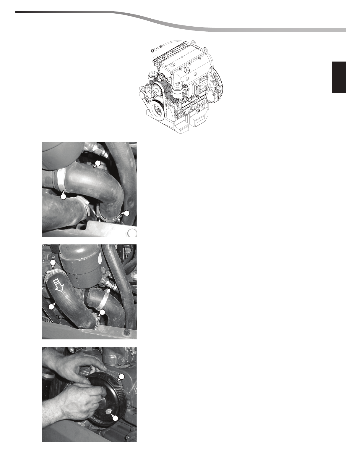
F - REMOVING THE ENGINE COOLING WATER PUMP
Carry out operation A.
b
Carry out the operations on the cooling system only if
the coolant temperature is below 30.
Slacken the 2 clamps (Ref. 1) on the lower hose (Ref. 2).
Place suitable sized containers to hold the quantity of liquid to
be collected under the engine compartment.
Disconnect the lower hose (Ref. 2) from the pump, slowly
discharge overpressure from the system, let the liquid drain out
of the cooling system, and empty it completely.
Slacken the 2 clamps (Ref. 3) on the upper hose (Ref. 4) and
disconnect it from the pump.
Slacken the 4 screws (Ref. 5) and remove the pulley (Ref. 6).
6
2
1
1
3
4
3
5
 Loading...