

Page 1

EN-USM1 A052020647837
MC 18-2 D K ST5 S1
MC 18-4 D K ST5 S1
OPERATOR'S MANUAL
(ORIGINAL INSTRUCTIONS)
Page 2

IMPORTANT
Carefully read and understand this instruction manual before using the lift truck.
It contains all information relating to operation, handling and lift truck equipment,
as well as important recommendations to be followed.
This document also contains precautions for use, as well as information on the servicing and routine maintenance required
to ensure the lift truck's continued safety of use and reliability.
WHENEVER YOU SEE THIS SYMBOL IT MEANS:
IMPORTANT
WARNING ! BE CAREFUL ! YOUR SAFETY OR THE SAFETY OF THE LIFT TRUCK IS AT RISK.
- This manual has been produced on the basis of the equipment list and the technical characteristics
given at the time of its design.
- The level of equipment of the lift truck depends on the options chosen and the country of sale.
- According to the lift truck options and the date of sale, certain items of equipment/functions described
herein may not be available.
- Descriptions and figures are non binding.
- MANITOU reserves the right to change its models and their equipment without being required to
update this manual.
- The MANITOU network, consisting exclusively of qualified professionals, is at your disposal to answer
all your questions.
- This manual is an integral part of the lift truck.
- It is to be kept in its storage space at all times for ease of reference.
- Hand this manual to the new owner if the lift truck is resold.
647837 M1 (A052020)
MC 18-2/18-4 D K ST5 S1
Page 3

1st ISSUE
UPDATED
A052020
Manitou BF S.A Limited liability company with a Board of Directors.
Head office: 430, Rue de l’Aubinière - 44150 Ancenis - FRANCE
Share capital: 39,548,949 euros
857 802 508 RCS Nantes.
Tel: +33 (0)2 40 09 10 11
www.manitou.com
This manual is for information purposes only. Any reproduction, copy, representation, recording, transfer, distribution, or other, in part
or in whole, in any format is prohibited. The plans, designs, views, commentaries and instructions, even the document organization
that are found in this document, are the intellectual property of MANITOU BF. Any violation of the aforementioned may lead to civil
and criminal prosecution. The logos as well as the visual identity of the company are the property of MANITOU BF and may not be
used without express and formal authorization. All rights are reserved.
647837 M1 (A052020)
MC 18-2/18-4 D K ST5 S1
Page 4
1 - OPERATING AND SAFETY INSTRUCTIONS
2 - DESCRIPTION
3 - MAINTENANCE
4 - OPTIONAL ATTACHMENTS FOR USE WITH THE RANGE
647837 M1 (A052020)
MC 18-2/18-4 D K ST5 S1
Page 5

1 - OPERATING AND SAFETY
INSTRUCTIONS
1 - 1
647837 M1 (A052020)
MC 18-2/18-4 D K ST5 S1
Page 6

1 - 2
647837 M1 (A052020)
MC 18-2/18-4 D K ST5 S1
Page 7

1 - 3
647837 M1 (A052020)
MC 18-2/18-4 D K ST5 S1
Page 8

1 - OPERATING AND SAFETY INSTRUCTIONS
INSTRUCTIONS TO THE COMPANY MANAGER 1-6
THE SITE
THE OPERATOR
THE LIFT TRUCK
INSTRUCTIONS
MAINTENANCE
1-6
1-6
1-6
A - THE TRUCK'S SUITABILITY FOR THE JOB . . . . . . . . . . . . . . . . . . . . . . . . . . . . . . . . . . . . . . . . . . . . . . . . . . . . . . . . . 1-6
B - ADAPTATION OF THE LIFT TRUCK TO STANDARD ENVIRONMENTAL CONDITIONS . . . . . . . . . . . . . . . . . . . . . . . . . . . . . . 1-6
C - MODIFICATION OF THE LIFT TRUCK. . . . . . . . . . . . . . . . . . . . . . . . . . . . . . . . . . . . . . . . . . . . . . . . . . . . . . . . . . . . 1-7
D - FRENCH ROAD TRAFFIC RULES . . . . . . . . . . . . . . . . . . . . . . . . . . . . . . . . . . . . . . . . . . . . . . . . . . . . . . . . . . . . . . 1-7
1-7
1-7
INSTRUCTIONS TO THE OPERATOR 1-8
FOREWORD
GENERAL INSTRUCTIONS
OPERATING INSTRUCTIONS UNLADEN AND LADEN
1-8
1-8
A - OPERATOR'S MANUAL. . . . . . . . . . . . . . . . . . . . . . . . . . . . . . . . . . . . . . . . . . . . . . . . . . . . . . . . . . . . . . . . . . . . 1-8
B - AUTHORISATION FOR USE IN FRANCE . . . . . . . . . . . . . . . . . . . . . . . . . . . . . . . . . . . . . . . . . . . . . . . . . . . . . . . . . . 1-8
C - MAINTENANCE . . . . . . . . . . . . . . . . . . . . . . . . . . . . . . . . . . . . . . . . . . . . . . . . . . . . . . . . . . . . . . . . . . . . . . . . 1-8
D - MODIFICATION OF THE LIFT TRUCK . . . . . . . . . . . . . . . . . . . . . . . . . . . . . . . . . . . . . . . . . . . . . . . . . . . . . . . . . . . 1-8
E - LIFTING PEOPLE . . . . . . . . . . . . . . . . . . . . . . . . . . . . . . . . . . . . . . . . . . . . . . . . . . . . . . . . . . . . . . . . . . . . . . . . 1-8
1-9
A - BEFORE STARTING THE LIFT TRUCK. . . . . . . . . . . . . . . . . . . . . . . . . . . . . . . . . . . . . . . . . . . . . . . . . . . . . . . . . . . . 1-9
B - DRIVER'S OPERATING INSTRUCTIONS . . . . . . . . . . . . . . . . . . . . . . . . . . . . . . . . . . . . . . . . . . . . . . . . . . . . . . . . . . 1-9
C - ENVIRONMENT . . . . . . . . . . . . . . . . . . . . . . . . . . . . . . . . . . . . . . . . . . . . . . . . . . . . . . . . . . . . . . . . . . . . . . . . 1-9
D - VISIBILITY . . . . . . . . . . . . . . . . . . . . . . . . . . . . . . . . . . . . . . . . . . . . . . . . . . . . . . . . . . . . . . . . . . . . . . . . . . . 1-10
E - STARTING THE LIFT TRUCK . . . . . . . . . . . . . . . . . . . . . . . . . . . . . . . . . . . . . . . . . . . . . . . . . . . . . . . . . . . . . . . . 1-10
F - DRIVING THE LIFT TRUCK . . . . . . . . . . . . . . . . . . . . . . . . . . . . . . . . . . . . . . . . . . . . . . . . . . . . . . . . . . . . . . . . . 1-11
G - STOPPING THE LIFT TRUCK . . . . . . . . . . . . . . . . . . . . . . . . . . . . . . . . . . . . . . . . . . . . . . . . . . . . . . . . . . . . . . . . 1-12
H - DRIVING THE LIFT TRUCK ON THE PUBLIC HIGHWAY . . . . . . . . . . . . . . . . . . . . . . . . . . . . . . . . . . . . . . . . . . . . . . . . 1-12
INSTRUCTIONS FOR HANDLING A LOAD
A - CHOICE OF ATTACHMENTS. . . . . . . . . . . . . . . . . . . . . . . . . . . . . . . . . . . . . . . . . . . . . . . . . . . . . . . . . . . . . . . . 1-13
B - WEIGHT OF LOAD AND CENTRE OF GRAVITY. . . . . . . . . . . . . . . . . . . . . . . . . . . . . . . . . . . . . . . . . . . . . . . . . . . . . 1-13
C - TRANSVERSE ATTITUDE OF THE LIFT TRUCK . . . . . . . . . . . . . . . . . . . . . . . . . . . . . . . . . . . . . . . . . . . . . . . . . . . . . 1-13
D - PICKING UP A LOAD ON THE GROUND . . . . . . . . . . . . . . . . . . . . . . . . . . . . . . . . . . . . . . . . . . . . . . . . . . . . . . . . 1-14
PICKING UP AND LAYING DOWN A HIGH LOAD ON TIRES . . . . . . . . . . . . . . . . . . . . . . . . . . . . . . . . . . . . . . . . . . . . . . . 1-14
1-13
LIFT TRUCK MAINTENANCE INSTRUCTIONS 1-16
GENERAL INSTRUCTIONS
MAINTENANCE
LUBRICANT AND FUEL LEVELS
HYDRAULICS
ELECTRICITY
WELDING
WASHING THE LIFT TRUCK
TRANSPORTING THE LIFT TRUCK
1-16
1-16
1-16
1-17
1-16
1-16
1-17
1-17
1 - 4
647837 M1 (A052020)
MC 18-2/18-4 D K ST5 S1
Page 9

IF THE LIFT TRUCK IS NOT TO BE USED FOR A LONG TIME 1-18
INTRODUCTION
PREPARING THE LIFT TRUCK
DEF (Diesel Exhaust Fluid) TANK
PROTECTING THE ENGINE
PROTECTING THE LIFT TRUCK
BRINGING THE LIFT TRUCK BACK INTO SERVICE
1-18
1-18
1-18
1-18
1-18
1-19
LIFT TRUCK DISPOSAL 1-20
RECYCLING OF MATERIALS
METALS . . . . . . . . . . . . . . . . . . . . . . . . . . . . . . . . . . . . . . . . . . . . . . . . . . . . . . . . . . . . . . . . . . . . . . . . . . . . . . 1-20
PLASTICS . . . . . . . . . . . . . . . . . . . . . . . . . . . . . . . . . . . . . . . . . . . . . . . . . . . . . . . . . . . . . . . . . . . . . . . . . . . . . 1-20
RUBBER . . . . . . . . . . . . . . . . . . . . . . . . . . . . . . . . . . . . . . . . . . . . . . . . . . . . . . . . . . . . . . . . . . . . . . . . . . . . . . 1-20
GLASS . . . . . . . . . . . . . . . . . . . . . . . . . . . . . . . . . . . . . . . . . . . . . . . . . . . . . . . . . . . . . . . . . . . . . . . . . . . . . . . 1-20
ENVIRONMENTAL PROTECTION
WORN OR DAMAGED PARTS . . . . . . . . . . . . . . . . . . . . . . . . . . . . . . . . . . . . . . . . . . . . . . . . . . . . . . . . . . . . . . . . . 1-20
USED OIL . . . . . . . . . . . . . . . . . . . . . . . . . . . . . . . . . . . . . . . . . . . . . . . . . . . . . . . . . . . . . . . . . . . . . . . . . . . . . 1-20
USED BATTERIES. . . . . . . . . . . . . . . . . . . . . . . . . . . . . . . . . . . . . . . . . . . . . . . . . . . . . . . . . . . . . . . . . . . . . . . . . 1-20
1-20
1-20
1 - 5
647837 M1 (A052020)
MC 18-2/18-4 D K ST5 S1
Page 10

INSTRUCTIONS TO THE COMPANY MANAGER
THE SITE
- Proper management of the lift truck's area of travel will reduce the risk of accidents:
• Ground not unnecessarily uneven or obstructed,
• No excessive slopes,
• Pedestrian traffic controlled, etc.
THE OPERATOR
- Only qualified, authorised personnel can use the lift truck. This authorisation is given in writing by the appropriate person
in the establishment with respect to the use of lift trucks and must be carried permanently by the operator.
IMPORTANT
Experience has shown that there are a number of inappropriate ways in which the lift truck might be used. Such foreseeable misuse, of which the main examples are listed
below, are strictly forbidden.
- The foreseeable abnormal behaviour resulting from ordinary negligence, but which does not result from any wish to put the machinery to any improper use.
- The reflex reactions of a person in the event of a malfunction, incident, fault, etc. during operation of the lift truck.
- Behaviour resulting from application of the "principle of least effort" when performing a task.
- For certain machines, the foreseeable behaviour of such persons as: apprentices, teenagers, handicapped persons, trainees tempted to drive a lift truck, operators
tempted to operate a truck for the purposes of a bet, a competition or for their own personal experience.
The person in charge of the equipment must take these criteria into account when assessing the suitability of a person to drive.
THE LIFT TRUCK
A - THE TRUCK'S SUITABILITY FOR THE JOB
- MANITOU has ensured that this lift truck is suitable for use under the standard operating conditions defined in this
operator's manual, with a STATIC TEST COEFFICIENT OF 1.33 and a DYNAMIC TEST COEFFICIENT OF 1, as specified in
harmonised standard ISO 3691-1 for mast trucks.
- Before commissioning, the company manager must make sure that the lift truck is appropriate for the work to be done,
and perform certain tests (in accordance with current legislation).
B - ADAPTATION OF THE LIFT TRUCK TO STANDARD ENVIRONMENTAL CONDITIONS
- In addition to series equipment mounted on your lift truck, many options are available, such as: road lighting, stop lights,
revolving light, reverse lights, reverse buzzer alarm, front light, rear light, etc.
- The operator must take into account the operating conditions to specify the lift truck's signalling and lighting equipment.
Contact your dealer.
- Take the climatic and atmospheric conditions of the site of use into account.
• Protection against frost (
• Adaptation of lubricants (ask your dealer for information).
• Engine filtration (
For operation under average climatic conditions, i.e.: between -15 °C and +35 °C, correct levels of lubricants in all the circuits are checked in production.
For operation under more severe climatic conditions, before starting up, it is necessary to drain all the circuits, then ensure correct levels of lubricants using lubricants
- Preventing fire risks associated with use in dusty and flammable conditions (e.g. straw, flour, sawdust, organic waste, etc.).
- A lift truck operating in an area without fire extinguishing equipment must be equipped with an individual extinguisher.
There are solutions, consult your dealer.
Your lift truck is designed for outdoor use under normal atmospheric conditions and indoor use in suitably aerated and ventilated premises.
It is prohibited to use the lift truck in areas where there is a risk of fire or which are potentially explosive (e.g. Refineries, fuel or gas depots, stores of flammable products,
3-MAINTENANCE).
3-MAINTENANCE).
IMPORTANT
properly suited to the relevant ambient temperatures.
The same applies to the cooling liquid.
IMPORTANT
etc.).
For use in these areas, specific equipment is available (ask your dealer for information).
1 - 6
647837 M1 (A052020)
MC 18-2/18-4 D K ST5 S1
Page 11

- Our lift trucks comply with Directive 2004/108/EC concerning electromagnetic compatibility (EMC), and with the
corresponding harmonised standard EN 12895. Their correct operation is no longer guaranteed if they are used within
areas in which the electromagnetic fields exceed the limit specified by this standard (10 V/m).
- Directive 2002/44/EC requires company managers to not expose their employees to excessive vibration doses. There is
no recognised code of measurement for comparing the machines of different manufacturers. The actual doses received
cannot therefore be measured under actual operating conditions at the user's premises.
- The following are some tips for minimising these vibration doses:
• Select the most suitable lift truck and attachment for the intended use.
• Adapt the seat adjustment to the operator's weight
as the cab suspensions. Inflate the tyres in accordance with recommendations.
• Ensure that the operators adapt their operating speed to suit the conditions on site.
• As far as possible, arrange the site in such a way as to provide a flat running surface and remove obstacles and harmful
potholes.
C - MODIFICATION OF THE LIFT TRUCK
- For your own safety and that of others, you must not change the structure and settings of the various components used
in your lift truck by yourself (hydraulic pressure, limiter calibration, engine speed, addition of extra equipment, addition
of counterweights, unapproved attachments, alarm systems, etc.). In this event, the manufacturer cannot be held liable.
D - FRENCH ROAD TRAFFIC RULES
- Only one certificate of conformity is issued. It must be kept in a safe place.
- The driving of non-approved lift trucks on the public highway is subject to the provisions of the highway code relating to
special machines, defined in article R311-1 of the highway code, in category B of the Equipment Order of 20 November
1969 that determines the procedures applicable to special machines. The lift truck must be fitted with a license plate.
(according to lift truck model)
and maintain it in good condition, as well
INSTRUCTIONS
- The operator's manual must always be in good condition and kept in the place provided on the lift truck and in the
language used by the operator.
- Operator's manuals and any plates or stickers which are no longer legible or are damaged, must be replaced.
MAINTENANCE
- Maintenance or repairs other than those detailed in part: 3-MAINTENANCE must be carried out by qualified personnel
(consult your dealer) and under the necessary safety conditions to maintain the health of the operator and any third party.
IMPORTANT
Your lift truck must be inspected periodically to ensure that it remains in compliance.
The frequency of this inspection is defined by current legislation in the country in which the lift truck is used.
- Example for France: “The manager in charge of the establishment using a lift truck must open and maintain a maintenance
log for each machine (Order of 2 March 2004) and undergo a general periodic inspection every 6 months (Order of 1
March 2004)”.
1 - 7
647837 M1 (A052020)
MC 18-2/18-4 D K ST5 S1
Page 12

INSTRUCTIONS TO THE OPERATOR
FOREWORD
IMPORTANT
The risk of accident while using, servicing or repairing your lift truck can be restricted if you follow the safety instructions and safety measures detailed in these
instructions.
Failure to respect the safety and operating instructions, or instructions for repairing or servicing your lift truck, may lead to serious, even fatal accident.
In order to reduce or avoid any danger with a MANITOU-approved attachment, follow the instructions of paragraph:4-ADAPTABLE ATTACHMENTS AVAILABLE ON THE
RANGE: INTRODUCTION.
- Only the operations and manoeuvres described in this operator's manual must be performed. The manufacturer cannot
predict all possible risky situations. Consequently, the safety instructions given in the operator's manual and on the lift
truck itself are not exhaustive.
- As operator, you must anticipate at all times the potential risks for yourself, for others and for the lift truck.
GENERAL INSTRUCTIONS
A - OPERATOR'S MANUAL
- Read the operator's manual carefully.
- The operator's manual must always be in good condition and in the place provided for it on the lift truck.
- You must report any plates and stickers which are no longer legible or which are damaged.
B - AUTHORISATION FOR USE IN FRANCE
(or see current legislation in other countries)
- Only qualified, authorised personnel can use the lift truck. This authorisation is given in writing by the appropriate person
in the establishment with respect to the use of lift trucks and must be carried permanently by the operator.
- The operator is not competent to authorise the driving of the lift truck by another person.
C - MAINTENANCE
- The operator must immediately advise his superior if his lift truck is not in good working order or does not comply with
the safety notice.
- The operator is prohibited from carrying out any repairs or adjustments himself, unless he has been trained for this
purpose. He must keep the lift truck properly cleaned if this is among his responsibilities.
- The operator must carry out daily and weekly maintenance (3-MAINTENANCE).
- For the safety of the operator, maintenance must be carried out with the engine off and the ignition key removed.
- The operator must ensure tyres are appropriate for the type of ground (2-DESCRIPTION). There are optional solutions,
consult your dealer.
• SAND tyres.
• FARM tyres.
• Snow chains.
IMPORTANT
Do not use the lift truck if the tyres are incorrectly inflated, damaged or excessively worn, because this could put your own safety or that of others at risk, or cause damage
to the lift truck itself.
The fitting of foam inflated tyres is prohibited and is not guaranteed by the manufacturer, excepting prior authorisation.
- The operator is responsible for deciding and adjusting the frequency of cleaning needed to prevent the risk of fire ensuing
from the build-up of flammable material(s).
- The operator should pay special attention to all the areas of the lift truck where these risk materials are likely to accumulate.
D - MODIFICATION OF THE LIFT TRUCK
- For your own safety and that of others, you must not change the structure and settings of the various components used
in your lift truck by yourself (hydraulic pressure, limiter calibration, engine speed, addition of extra equipment, addition
of counterweights, unapproved attachments, alarm systems, etc.). In this event, the manufacturer cannot be held liable.
E - LIFTING PEOPLE
- It is forbidden to lift or carry people.
1 - 8
647837 M1 (A052020)
MC 18-2/18-4 D K ST5 S1
Page 13

OPERATING INSTRUCTIONS UNLADEN AND LADEN
A - BEFORE STARTING THE LIFT TRUCK
- Perform the daily maintenance operations (3-MAINTENANCE).
- Make sure that the driver's cab is clean, particularly the floor and floor mat. Check that no movable objects can hinder
operation of the lift truck.
- Make sure the lights, indicators and windscreen wipers are working properly.
- Make sure the rear view mirrors are in good condition, clean and properly adjusted.
- Make sure the horn works.
B - DRIVER'S OPERATING INSTRUCTIONS
IMPORTANT
Under no circumstances must the seat be adjusted while the lift truck is moving.
- Whatever his experience, the operator is advised to familiarise himself with the position and operation of all the controls
and instruments before operating the lift truck.
- Wear clothes suited for driving the lift truck, avoid loose clothes.
- Make sure you have the appropriate protective equipment for the task to be performed.
- Prolonged exposure to high noise levels may cause hearing problems. It is recommended to wear ear muffs to protect
against excessive noise.
- Always face the lift truck when getting into and out of the driver's cab.
• Use the handle(s) provided for this purpose.
• Use the step(s).
• Do not jump out of the lift truck.
- Always pay attention when using the lift truck. Do not listen to the radio or music using headphones or earphones.
- Never operate the lift truck when hands or feet are wet or soiled with greasy substances.
- For increased comfort, adjust the seat to your requirements and adopt the correct position in the driver’s cab.
- The operator must always be in his normal position in the driver’s cab. It is prohibited to have arms or legs, or generally
any part of the body, protruding from the driver’s cab of the lift truck.
- The safety belt must be worn and adjusted to the operator's size.
- The control units must never in any event be used for any other than their intended purposes (e.g. climbing onto or down
from the lift truck, portmanteau, etc.).
- If the control components are fitted with a forced operation (lever lock) device, it is forbidden to leave the cab without
first putting these controls in neutral.
- It is prohibited to carry passengers either on the lift truck or in the cab.
C - ENVIRONMENT
- Comply with site safety regulations.
- If you have to use the lift truck in a dark area or at night, make sure it is equipped with working lights.
- During handling operations, make sure that no one is in the way of the lift truck and its load.
- Do not allow anybody to come near the working area of the lift truck or pass beneath an elevated load.
- When using the lift truck on a transverse slope, before lifting the mast, follow the instructions given in the paragraph:
INSTRUCTIONS FOR HANDLING A LOAD.
- Travelling on a longitudinal slope:
• Drive and brake gently.
• Moving without load: Forks or attachment facing downhill.
• Moving with load: Forks or attachment facing uphill.
- Take into account the lift truck’s dimensions and its load before trying to negotiate a narrow or low passageway.
- Never move onto a loading platform without having first checked:
• That it is suitably positioned and made fast.
• That the unit to which it is connected (wagon, lorry, etc.) will not shift.
• That this platform is prescribed for the total weight of the lift truck to be loaded.
• That this platform is prescribed for the size of the lift truck.
- Never move onto a foot bridge, floor or freight lift, without being certain that they are prescribed for the weight and size
of the lift truck to be loaded and without having checked that they are in sound working order.
- Be careful in the area of loading bays, trenches, scaffolding, soft ground and manholes.
- Make sure the ground is stable and firm under the wheels before lifting the load.
- Make sure that the scaffolding, loading platform, pilings or ground is capable of bearing the load.
1 - 9
647837 M1 (A052020)
MC 18-2/18-4 D K ST5 S1
Page 14

- Never stack loads on uneven ground, they may tip over.
- The load or the attachment must not be left just above a structure for long periods at a time because of the descending
mast. In such a case, a constant watch must be kept and the height of the forks or the attachment readjusted if necessary.
- When working near aerial lines, ensure that the safety distance is sufficient between the working area of the lift truck
and the aerial line.
IMPORTANT
You must consult your local electrical agency.
You could be electrocuted or seriously injured if you operate or park the lift truck too close to power cables.
In the event of high winds, do not carry out handling work that jeopardises the stability of the lift truck and its load, particularly if the load catches the wind badly.
- Prevent fire risks associated with use in dusty and flammable conditions (e.g. straw, flour, sawdust, organic waste, etc.).
D - VISIBILITY
- The safety of people within the lift truck's working area, as well as that of the lift truck itself and the operator are depend
on good operator visibility of the lift truck's immediate vicinity in all situations and at all times.
- This lift truck has been designed to allow good operator visibility (direct or indirect by means of rear-view mirrors) of the
immediate vicinity of the lift truck while travelling with no load and with the mast in the transport position.
- Special precautions must be taken if the size of the load restricts visibility towards the front:
• Moving in reverse,
• Site layout,
• assisted by a person directing the manoeuvre (while standing outside the truck's area of travel), making sure to keep
this person clearly in view at all times,
• In any event, avoid reversing over long distances.
- If visibility of your road is inadequate, ask someone to assist by directing the manoeuvre (while standing outside the
truck's area of travel), making sure to keep this person clearly in view at all times.
- Keep all components affecting visibility in a clean, properly adjusted state and in good working order (e.g. windscreens,
windows, windscreen wipers, windscreen washers, driving and work lights, rear-view mirrors).
E - STARTING THE LIFT TRUCK
SAFETY INSTRUCTIONS
IMPORTANT
The lift truck must only be started up or manoeuvred when the operator is sitting in the driver’s cab, with his seat belt adjusted and fastened.
- Never try to start the lift truck by pushing or hauling it. Such an operation may cause severe damage to the transmission.
If necessary, towing requires the transmission to be put in neutral ( 3 - MAINTENANCE).
- If using an emergency battery for start-up, use a battery with the same characteristics and respect battery polarity when
connecting it. Connect at first the positive terminals before the negative terminals.
IMPORTANT
Failure to respect polarity between batteries can cause serious damage to the electrical circuit.
The electrolyte in the battery may produce an explosive gas. Avoid flames and generation of sparks close to the batteries.
Never disconnect a battery while it is charging.
INSTRUCTIONS
- Check the closing and locking of the hood(s).
- For lift trucks operating on gas carburisation, open the gas bottle.
- Ensure that the forward/reverse selector is set to neutral.
- Turn the ignition key to the position I to activate the electrical and preheat system.
- Check the fuel level on the indicator.
- Turn the ignition key fully, the engine should then start. Release the ignition key and let the engine run at idle.
- Do not engage the starter motor for more than 15 seconds and carry out the preheating between unsuccessful attempts.
- Make sure all the signal lights on the control instrument panel are off.
- Check all control instruments when the engine is warm and at regular intervals during use, so as to quickly detect any
faults and to be able to correct them without any delay.
- If an instrument does not show the correct display, stop the engine and immediately carry out the necessary operations.
1 - 10
647837 M1 (A052020)
MC 18-2/18-4 D K ST5 S1
Page 15

F - DRIVING THE LIFT TRUCK
SAFETY INSTRUCTIONS
IMPORTANT
The operators' attention is drawn to the risks involved in using the lift truck, in particular:
- Risk of losing control.
- Risk of losing lateral and frontal stability of the lift truck.
The operator must remain in control of the lift truck.
In the event of the lift truck overturning, do not try to leave the cabin during the incident.
YOUR BEST PROTECTION IS TO STAY FASTENED IN THE CABIN.
- Observe the company’s traffic regulations or, by default, the public highway code.
- Do not carry out operations which exceed the capacities of your lift truck or attachments.
- Always drive the lift truck with the forks or attachment to the transport position, i.e. at 300 mm from the ground and the
carriage sloping backwards.
- Only carry loads which are balanced and properly anchored to avoid any risk of a load falling off.
- Ensure that pallets, cases, etc. are in good order and suitable for the load to be lifted.
- Familiarise yourself with the lift truck on the terrain where it will be used.
- Ensure that the service brakes are working properly.
- The loaded lift truck must not travel at speeds in excess of 12 km/h.
- Drive smoothly at an appropriate speed for the operating conditions (land configuration, load on the lift truck).
- Do not use the hydraulic mast controls when the lift truck is moving.
- Do not manoeuvre the lift truck with the mast in the raised position unless under exceptional circumstances and then
with extreme caution, at very low speed and using gentle braking. Ensure that visibility is adequate.
- Take bends slowly.
- In all circumstances make sure you are in control of your speed.
- On damp, slippery or uneven terrain, drive slowly.
- Brake gently, never abruptly.
- Only use the lift truck’s forward/reverse selector from a stationary position and never do so abruptly.
- Do not drive with your foot on the brake pedal.
- Always remember that hydrostatic type steering is extremely sensitive to movement of the steering wheel, so turn it
gently and not jerkily.
- Never leave the engine running when the lift truck is unattended.
- Do not leave the cab when the lift truck has a raised load.
- Look where you are going and always make sure you have good visibility along the route.
- Use the rear-view mirrors frequently.
- Drive round obstacles.
- Never drive on the edge of a ditch or steep slope.
- It is dangerous to use two lift trucks simultaneously to handle heavy or voluminous loads, since this operation requires
particular precautions to be taken. It must only be used exceptionally and after risk analysis.
- The ignition switch has an emergency stop mechanism in case of an operating anomaly occurring in the case of lift trucks
not fitted with a punch-operated cut-out.
INSTRUCTIONS
- Always drive the lift truck with the forks or attachment to the transport position, i.e. at 300 mm from the ground and the
carriage sloping backwards.
- For lift trucks with gearboxes, use the selected gear (
- Release the hand brake.
- Shift the forward/reverse selector to the selected direction of travel and accelerate gradually until the lift truck moves off.
2-DESCRIPTION).
1 - 11
647837 M1 (A052020)
MC 18-2/18-4 D K ST5 S1
Page 16

G - STOPPING THE LIFT TRUCK
SAFETY INSTRUCTIONS
- Never leave the ignition key in the lift truck during the operator's absence.
- When the lift truck is stationary, or if the operator has to leave his cab (even for a moment), place the forks or attachment
on the ground, apply the parking brake and place the forward/reverse selector in neutral.
- Make sure that the lift truck is not stopped in any position that will interfere with the traffic flow and at less than one
metre from the track of a railway.
- In the event of prolonged parking on a site, protect the lift truck from bad weather, particularly from frost (check the
level of antifreeze), close and lock all the lift truck accesses (doors, windows, cowls, etc.).
INSTRUCTIONS
- Park the lift truck on flat ground or on an incline lower than 15%.
- Set the forward/reverse selector to neutral.
- Apply the parking brake.
- For lift trucks with gearboxes, place the gear lever in neutral.
- Lower the forks or attachment to rest on the ground.
- When using an attachment with a grab or jaws, or a bucket with hydraulic opening, close the attachment fully.
- Before stopping the lift truck after a long working period, leave the engine idling for a few moments, to allow the coolant
liquid and oil to lower the temperature of the engine and transmission. Do not forget this precaution, in the event of
frequent stops or warm stalling of the engine, or else the temperature of certain parts will rise significantly due to the
stopping of the cooling system, with the risk of badly damaging such parts.
- Stop the engine with the ignition switch.
- Remove the ignition key.
- Lock all the accesses to the lift truck (doors, windows, cowls…).
- For lift trucks operating on gas carburisation, shut the LPG bottle. For a long lasting stop, let the engine stop naturally by
shutting the LPG bottle before switching off the ignition, so as to eliminate all the fuel in the feed tube.
H - DRIVING THE LIFT TRUCK ON THE PUBLIC HIGHWAY
FRENCH ROAD TRAFFIC RULES
- The driving of non-approved lift trucks on the public highway is subject to the provisions of the highway code relating to
special machines, defined in article R311-1 of the highway code, in category B of the Equipment Order of 20 November
1969 that determines the procedures applicable to special machines. The lift truck must be fitted with a license plate.
SAFETY INSTRUCTIONS
- Operators driving on the public highway must comply with current highway code legislation.
- The lift truck must comply with current road legislation. If necessary, there are optional solutions. Contact your dealer.
INSTRUCTIONS
- Make sure the revolving light is in place, switch it on and verify its operation.
- Make sure the lights, indicators and windscreen wipers are working properly.
- Switch off the working headlights if the lift truck is fitted with them.
- Place the attachment 300 mm from the ground.
IMPORTANT
Never coast in neutral (forward/reverse selector or gear lever in neutral or transmission cut-off button pressed) to preserve the lift truck engine brake.
Failure to observe this instruction on a slope will lead to excessive speed which may make the lift truck uncontrollable (steering, brakes) and cause serious mechanical
damage.
DRIVING THE LIFT TRUCK WITH A FRONT-MOUNTED ATTACHMENT
- You must comply with current regulations in your country, covering the possibility of driving on the public highway with
a front-mounted attachment on your lift truck.
- If road legislation in your country authorises circulation with a front-mounted attachment, you must at least:
• Protect and report any sharp and/or dangerous edges on the attachment (
ON THE RANGE).
• The attachment must not be loaded.
• Make sure that the attachment does not mask the lighting range of the forward lights.
• Make sure that current legislation in your country does not require other obligations.
4-ADAPTABLE ATTACHMENTS AVAILABLE
1 - 12
647837 M1 (A052020)
MC 18-2/18-4 D K ST5 S1
Page 17
For lift trucks equipped with a towing system
OPERATING THE LIFT TRUCK WITH A TRAILER
- For using a trailer, observe the regulations in force in your country (maximum travel speed, braking, maximum weight
of trailer, etc.).
- Do not forget to connect the trailer’s electrical equipment to that of the lift truck.
- The trailer's braking system must comply with current legislation.
- If pulling a trailer with assisted braking, the tractor lift truck must be equipped with a trailer braking mechanism. In this
case, do not forget to connect the trailer braking equipment to the lift truck.
- The vertical force on the towing hook must not exceed the maximum authorised by the manufacturer (consult the
manufacturer’s plate on your lift truck).
- The authorised gross vehicle weight must not exceed the maximum weight authorised by the manufacturer (consult
the manufacturer’s plate on your lift truck).
IF NECESSARY, CONSULT YOUR DEALER.
INSTRUCTIONS FOR HANDLING A LOAD
A - CHOICE OF ATTACHMENTS
- Only attachments approved by MANITOU can be used on its lift trucks.
- Make sure the attachment is appropriate for the work to be done (4-ADAPTABLE ATTACHMENTS AVAILABLE ON THE
RANGE).
- Make sure the attachment is correctly installed and locked onto the lift truck carriage.
- Make sure that your lift truck attachments work properly.
- Comply with the load chart limits for the lift truck for the attachment used.
- Do not exceed the rated capacity of the attachment.
- Never lift a load in a sling without the attachment provided for the purpose. There are optional solutions; contact your
dealer.
B - WEIGHT OF LOAD AND CENTRE OF GRAVITY
- Before picking up a load, you must know its weight and its centre of gravity.
- The load chart for your lift truck is valid for a load in which the longitudinal position
of the centre of gravity is 500mm or 600 mm from the base of the forks
on the model of lift truck)
- For irregular loads, determine the transverse centre of gravity before any movement
(fig. B2) and set it in the longitudinal axis of the lift truck.
It is forbidden to move a load heavier than the effective capacity defined on the lift truck load chart.
For loads with a moving centre of gravity (e.g. liquids), take account of the variations in the centre of gravity in order
to determine the load to be handled and be extra vigilant and careful to limit these variations as far as possible.
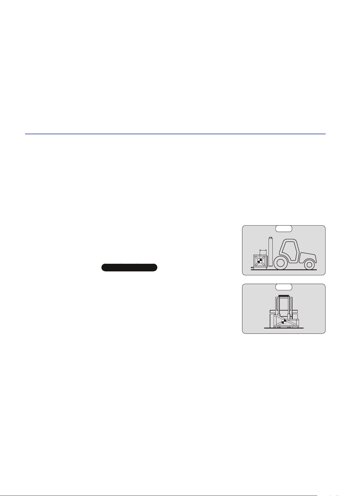
C - TRANSVERSE ATTITUDE OF THE LIFT TRUCK
- The transverse attitude is the lateral tilt of the frame in relation to the floor.
- Raising the mast reduces the lift truck's lateral stability.
- The transverse attitude must be horizontal with the mast in the down position:
Depending on the model of lift truck
• Position the lift truck so that the bubble in the spirit level is between the two lines (2-DESCRIPTION).
(Fig. B1). For a higher centre of gravity, contact your dealer.
IMPORTANT
(depending
500 mm
B1
B2
1 - 13
647837 M1 (A052020)
MC 18-2/18-4 D K ST5 S1
Page 18
D - PICKING UP A LOAD ON THE GROUND
- Approach the lift truck perpendicular to the load, with the forks in a horizontal
position (fig. D1).
- Adjust the fork spread and centring in connection with the load (fig. D2) (optional
solutions exist, consult your dealer).
- Never lift a load with a single fork.
IMPORTANT
Beware of the risks of trapping or crushing limbs when manually adjusting the forks.
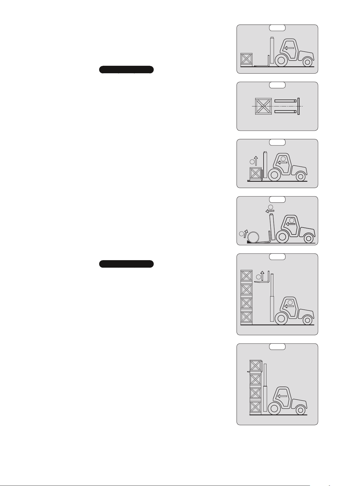
- Move the lift truck forward slowly (1) and bring the forks to stop in front of the load
(fig. D3), if necessary, slightly lift the mast (2) while taking up the load.
- Bring the load into the transport position.
- Tilt the load far enough backwards to ensure stability (loss of load on braking or
going downhill).
D1
D2
D3
FOR A NON-PALLETISED LOAD
- Tilt the carriage (1) forwards and move the lift truck slowly forwards (2), to insert
the fork under the load (fig. D4) (block the load if necessary).
- Continue to move the lift truck forwards (2) tilting the carriage (3) (fig. D4) backwards
to position the load on the forks and check the load's longitudinal and lateral stability.
PICKING UP AND LAYING DOWN A HIGH LOAD ON TIRES
IMPORTANT
You must not raise the mast if you have not checked the transverse attitude of the lift truck (INSTRUCTIONS FOR
HANDLING A LOAD).
REMINDER: Make sure that the following operations can be performed with good
visibility ( OPERATION INSTRUCTIONS UNLADEN AND LADEN).
PICKING UP A HIGH LOAD ON TIRES
- Ensure that the forks will easily pass under the load.
- Keeping the mast vertical (1), advance the lift truck and raise the forks to level with
the load (2) (fig. E1).
- Manoeuvre carefully and gently to bring the forks to the stop in front of the load
(fig. E2). Set the handbrake and place the forward/reverse selector to neutral.
2
1
D4
1
2
3
E1
2
1
E2
1 - 14
647837 M1 (A052020)
MC 18-2/18-4 D K ST5 S1
Page 19
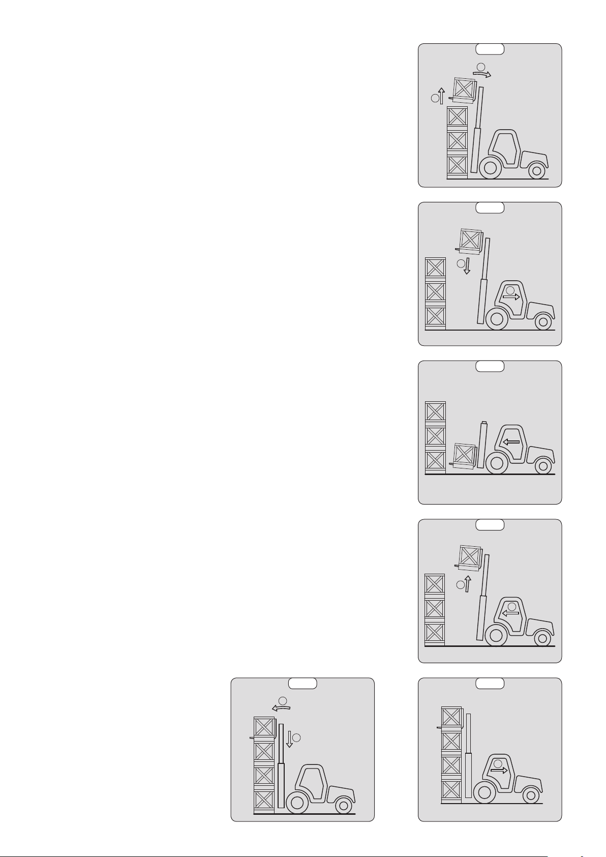
- Slightly raise the load (1) and tilt the carriage (2) backwards to stabilise the load
(fig. F3).
- Tilt the load sufficiently backwards to ensure its stability.
- Reverse the lift truck (1) very carefully and gently to free the load. Lower the mast
(2) to bring the load into transport position (fig. E4).
E3
2
1
E4
2
1
LAYING A HIGH LOAD ON TYRES
- Approach the load in the transport position in front of the pile (fig. E5).
- Raise the mast (1) until the load is higher than the pile and move the lift truck
forward (2) (fig. E6) very carefully and gently, until the load is over the pile. Put the
handbrake on and set the forward/reverse selector to neutral.
- Place the load in a horizontal position by tilting the mast forwards (1) and lay it
down on the pile (2) while checking the correct positioning of the load (fig. E7).
- Reverse the lift truck (1) very slowly and carefully to release the forks (fig. E8). Then
set them into transport position.
E5
E6
1
2
1
E7
2
1 - 15
E8
1
647837 M1 (A052020)
MC 18-2/18-4 D K ST5 S1
Page 20

LIFT TRUCK MAINTENANCE INSTRUCTIONS
GENERAL INSTRUCTIONS
- Ensure the area is sufficiently ventilated before starting the lift truck.
- Wear clothes suitable for the maintenance of the lift truck, avoid wearing jewellery and loose clothes. Tie back and protect
your hair, if necessary.
- Before carrying out any work on the lift truck:
• Switch off the engine
• Apply the parking brake.
• Remove the ignition key.
- Read the operator's manual carefully.
- Carry out all repairs immediately, even if the repairs concerned are minor.
- Repair all leaks immediately, even if the leak concerned is minor.
- Ensure that process materials and of spare parts are disposed in all safely and in an ecological manner.
- Be careful of the risk of burning and splashing (exhaust, radiator, engine, etc.).
MAINTENANCE
- Perform the periodic service (3-MAINTENANCE) to keep your lift truck in good working condition. Failure to perform
the periodic service may invalidate the contractual warranty.
MAINTENANCE LOGBOOK
- The maintenance operations carried out in accordance with the recommendations given in Part: 3 - MAINTENANCE and
the other inspection, servicing or repair operations or modifications performed on the lift truck or its attachments are
recorded in a maintenance logbook. The entry for each operation should include the date of the work, the names of
the individuals or companies having performed them, the type of operation and its frequency, if applicable. The part
numbers of any lift truck components that are replaced are indicated.
LUBRICANT AND FUEL LEVELS
- Use the recommended lubricants (never use contaminated lubricants).
- Do not fill the fuel tank when the engine is running.
- Only fill up the fuel tank in areas specified for this purpose.
- Do not fill the fuel tank to the maximum level.
- Do not smoke or approach the lift truck with a flame, when the fuel tank is open or is being filled.
HYDRAULICS
- Any work on the load handling hydraulic circuit is forbidden except for the operations described in Part: 3 - MAINTENANCE.
- Do not attempt to loosen connections, hoses or a hydraulic component with the circuit under pressure.
IMPORTANT
It is dangerous to change the setting and remove the BALANCING VALVES or SAFETY VALVES which may be fitted to your lift truck cylinders.
The HYDRAULIC ACCUMULATORS that may be fitted on your lift truck are pressurised units.
Removing these accumulators and their pipework is dangerous.
Such operations must only be performed by approved personnel (consult your dealer).
ELECTRICITY
- Do not short-circuit the starter relay to start the engine. If the forward/reverse selector is not in neutral and the parking
brake is not applied, the lift truck may suddenly start to move.
- Do not place metal items on the battery.
- Disconnect the battery before working on the electrical circuit.
1 - 16
647837 M1 (A052020)
MC 18-2/18-4 D K ST5 S1
Page 21

WELDING
- Disconnect the battery before any welding operations on the lift truck.
- When carrying out electric welding work on the lift truck, connect the negative cable from the equipment directly to the
part being welded, so as to avoid high tension current passing through the alternator.
- Never carry out welding or work which gives off heat on an assembled tire. The heat would increase the pressure which
could cause the tire to explode.
- If the lift truck is equipped with an electronic control unit, disconnect this before starting to weld, to avoid the risk of
causing irreparable damage to electronic components.
WASHING THE LIFT TRUCK
- Clean the lift truck or at least the area concerned before any intervention.
- Remember to close and lock all accesses to the lift truck (doors, windows, cowls…).
- During washing, avoid the articulations and electrical components and connections.
- If necessary, protect against penetration of water, steam or cleaning agents, components susceptible of being damaged,
particularly electrical components and connections and the injection pump.
- Clean the lift truck of any fuel, oil or grease trace.
TRANSPORTING THE LIFT TRUCK
IMPORTANT
Transporting the lift truck involves real risks for the operator and others involved.
- Towing, slinging or transporting the lift truck (3-MAINTENANCE).
1 - 17
647837 M1 (A052020)
MC 18-2/18-4 D K ST5 S1
Page 22

IF THE LIFT TRUCK IS NOT TO BE USED FOR A LONG TIME
INTRODUCTION
The following recommendations are intended to prevent the lift truck from being damaged when it is withdrawn from service
for an extended period.
IMPORTANT
Procedures to follow if the lift truck is not to be used for a long time and for starting it up again afterwards must be performed by your dealership.
This period of long-term stoppage must not exceed 12 months.
PREPARING THE LIFT TRUCK
- Clean the lift truck thoroughly.
- Check and repair any leakage of fuel, oil, water or air.
- Replace or repair any worn or damaged parts.
- Wash the painted surfaces of the lift truck in clear and cold water and wipe them.
- Touch up the paintwork if necessary.
- Shut down the lift truck ( OPERATING INSTRUCTIONS UNLADEN AND LADEN).
- Make sure the mast cylinder rods are all in retracted position.
- Release the pressure in the hydraulic circuits.
DEF (Diesel Exhaust Fluid) TANK
Depending on the model of lift truck
- Empty and rinse the "DEF" tank.
- Replace the "DEF" (Diesel Exhaust Fluid) feed pump filter (
- Fill up with new "DEF" (Diesel Exhaust Fluid) (2-DESCRIPTION).
- Start up the lift truck to pressurise the circuit and bring it up to working temperature.
- Switch off the engine.
- Check the "DEF" level and top up if required.
3-MAINTENANCE).
PROTECTING THE ENGINE
- Contact your dealer to obtain the procedure for protecting the inside of the engine (use of protection product).
- Fill the tank with fuel ( 3 - MAINTENANCE).
- Replace the coolant (3-MAINTENANCE).
- Leave the engine running at idling speed for a few minutes, then switch off.
- Replace the engine oil and oil filter (3-MAINTENANCE).
- Run the engine for a short time so that the oil and coolant circulate inside.
- Disconnect the battery and store it in a safe place away from the cold, after charging it to a maximum.
- Block the outlet with waterproof adhesive tape.
- Remove the drive belts and store them in a safe place.
- Disconnect the engine cut-off solenoid on the injection pump and carefully insulate the connection.
PROTECTING THE LIFT TRUCK
- Set the lift truck on axle stands so that the tyres are not in contact with the ground and release the parking brake.
- Protect cylinder rods which will not be retracted, from corrosion.
- Wrap the tyres.
NOTE: If the lift truck is to be stored outdoors, cover it with a waterproof tarpaulin.
1 - 18
647837 M1 (A052020)
MC 18-2/18-4 D K ST5 S1
Page 23

BRINGING THE LIFT TRUCK BACK INTO SERVICE
- Remove the waterproof adhesive tape from all the holes.
- Refit and reconnect the battery.
- Remove the protection from the cylinder rods.
- Perform the daily maintenance operations (
- Put the handbrake on and remove the axle stands.
- Drain and clean the fuel tank (3-MAINTENANCE).
- Fill the fuel tank with clean diesel filtered through the filler port.
- Replace the fuel filter ( 3 - MAINTENANCE).
- Replace the fuel pre-filter (3-MAINTENANCE)
- Drain and rinse the DEF tank
- Top up, slowly fill the tank with new "DEF" (Diesel Exhaust Fluid) up to the bottom of the filler neck
of lift truck)
- Refit the drive belts and adjust the tension ( 3 - MAINTENANCE).
- Turn the engine over with the starter, to allow the oil pressure to rise.
- Reconnect the engine cut-off solenoid.
- Lubricate the lift truck completely ( 3 - MAINTENANCE).
- Start up the lift truck, following the safety instructions and regulations ( OPERATING INSTRUCTIONS UNLADEN AND
LADEN).
- Run all the jib's hydraulic movements, concentrating on the ends of travel for each cylinder.
(depending on the model of lift truck)
Ensure the area is sufficiently ventilated before starting the lift truck.
3 - MAINTENANCE).
(depending on the model of lift truck)
IMPORTANT
(depending on the model
1 - 19
647837 M1 (A052020)
MC 18-2/18-4 D K ST5 S1
Page 24

LIFT TRUCK DISPOSAL
IMPORTANT
Please consult your dealer before disposing of your lift truck.
RECYCLING OF MATERIALS
METALS
• Metals are 100% recoverable and recyclable.
PLASTICS
• Plastic parts are identified with a marking in accordance with current regulations.
• A limited range of materials is used to simplify the recycling process.
• The majority of the plastic components are made of "thermoplastic" plastics, which are easily recycled by melting,
granulating or grinding.
RUBBER
• Tyres and seals can be ground for use in cement manufacture or to obtain reusable granules.
GLASS
• Glass items can be removed and collected for processing by glaziers.
ENVIRONMENTAL PROTECTION
By entrusting the maintenance of your lift truck to the MANITOU network, the risk of pollution is limited and the contribution
to environmental protection contribution is made.
WORN OR DAMAGED PARTS
• Do not dump them in the countryside.
• MANITOU and its network have signed-up to a scheme of environmental protection through recycling.
USED OIL
• The MANITOU network organises the collection and processing of used oil.
• By handing over your waste oil to MANITOU, the risk of pollution is limited.
USED BATTERIES
• Do not throw away batteries, as they contain metals that are harmful for the environment.
• Return them to the MANITOU network or any other approved collection point.
NOTE: MANITOU aims to manufacture lift trucks that provide the best performance and limit polluting emissions.
1 - 20
647837 M1 (A052020)
MC 18-2/18-4 D K ST5 S1
Page 25

2 - DESCRIPTION
2-1
647837 M1 (A052020)
MC 18-2/18-4 D K ST5 S1
Page 26

2-2
647837 M1 (A052020)
MC 18-2/18-4 D K ST5 S1
Page 27

2 - DESCRIPTION
DECLARATION CE OF CONFORMITY
SAFETY PLATES AND STICKERS
IDENTIFICATION OF THE LIFT TRUCK
SPECIFICATIONS
SPECIFICATIONS
MC 18-2...
MC 18-4...
MAST CHARACTERISTICS AND LOAD CHARTS
TYRES
INSTRUMENTS AND CONTROLS
SLINGING AND SECURING PIN
4
6
8
10
12
14
16
18
48
2-3
647837 M1 (A052020)
MC 18-2/18-4 D K ST5 S1
Page 28

DECLARATION CE OF CONFORMITY
gnat
:
:
tion
:
Date,
Date
exe
d’atte
Notified bod
and their trans
8-4 D K ST5 S1
Declares th
ns into n
1) DÉCLARATION «CE» DE CONFORMITÉ (originale)
«EC» DECLARATION OF CONFORMITY (original)
2) La société, The company : MANITOU BF
3) Adresse, Address : 430, rue de l’Aubinière - BP 10249 - 44158 - ANCENIS CEDEX - FRANCE
Dossier technique, Technical file : MANITOU BF - 430, rue de l’Aubinière
4)
BP 10249 - 44158 - ANCENIS CEDEX - FRANCE
Constructeur de la machine décrite ci-après, Manufacturer of the machine described below :
5)
MC 18-2 D K ST5 S1
MC 18-4 D K ST5 S1
Déclare que cette machine, Declares that this machine :
6)
17) Fait à, Done at : 18) Date, Date :
7) Est conforme aux directives suivantes et à leurs transpositions en droit national,
Complies with the following directives and their transpositions into national law :
8) Pour les machines annexe IV, For annex IV machines :
9) Numéro d’attestation, Certificate number :
10) Organisme notifié, Notified body :
15) Normes harmonisées utilisées, Harmonised standards used :
16) Normes ou dispositions techniques utilisées,
2006/42/CE
Standards or technical provisions used
:
19) Nom du signataire, Name of signatory :
20) Fonction, Function :
21) Signature, Signature :
2-4
647837 M1 (A052020)
MC 18-2/18-4 D K ST5 S1
Page 29

bg : 1) удостоверение за « СЕ » съответствие (oригинална), 2) Фирмата, 3) Адрес, 4) Техническо досие, 5) Фабрикант на описаната по-долу машина, 6) Обявява, че тази машина, 7)
, 2) N
harmonizované normy, 16) použité iné t
a)
, 2) Dr
, 2)
zharmonizowanych, 16) in
conformidade CE (origina
rmas harmonizada
, 2) Soc
inali)
, 2, segwent
, 2) H
is met de volgende richtl
erde geharmoniseer
tie, 21) Handteke
s, 4) do
zzo, 4) fa
esas, 4) T
kumā, 9) Apliecības numurs, 10) Reģistrētā
akstītāja vārds, 20) Amats, 21) Paraksts.
nija, 3) Indirizz, 4) fajl tekni
ti, 8) Fyrir tækin í
dirritaðs, 20) Staða, 2
ro d
kasutatakse, 17) V
Allekirjoittajan nimi, 20) T
uisín
ez, 9) Bizonylati szám, 1
, 19) Aláíró neve,
Staðfesting
) Κατασ
ύνται, 16) Πρότυπα ή τε
ctor de la máquina descrita a continuación, 6) Dec
tootja, 6) Kinnitab, et see to
koht, 18) Väljaa
IV, 9) Číslo certifi
5) harmoniserede s
r die Maschinen l
und Spezifikatio
εξής περιγραφό
α μηχανήματα
Отговаря на следните директиви и на тяхното съответствие национално право, 8) За машините към допълнение IV, 9)Номер на удостоверението, 10) Наименувана фирма, 15)
хармонизирани стандарти използвани, 16) стандарти или технически правила, използвани, 17) Изработено в, 18) Дата, 19) Име на разписалия се, 20) Функция, 21) Функция.
ES prohlášení o shodě (původní), 2) Název společnosti, 3) Adresa, 4) Technická dokumentace, 5) Výrobce níže uvedeného stroje, 6) Prohlašuje, že tento stroj,
cs : 1)
7) Je v souladu s následujícími směrnicemi a směrnicemi transponovanými do vnitrostátního práva, 8) Pro stroje v příloze IV, 9) Číslo certifikátu, 10) Notifikační orgán,
15) harmonizované normy použity, 16) Norem a technických pravidel používaných, 17) Místo vydání, 18) Datum vydání, 19) Jméno podepsaného, 20) Funkce, 21) Podpis.
EF Overensstemmelseserklæring (original), 2) Firmaet, 3) Adresse, 4) tekniske dossier, 5) Konstruktør af nedenfor beskrevne maskine, 6) Erklærer, at denne maskine,
da : 1)
7) Overholder nedennævnte direktiver og disses gennemførelse til national ret, 8) For maskiner under bilag IV, 9) Certifikat nummer, 10) Bemyndigede organ, 15) harmoniserede standarder,
der anvendes, 16) standarder eller tekniske regler, 17) Udfærdiget i, 18) Dato, 19) Underskrivers navn, 20) Funktion, 21) Underskrift.
de : 1)
EG-Konformitätserklärung (original), 2) Die Firma, 3) Adresse, 4) Technischen Unterlagen, 5) Hersteller der nachfolgend beschriebenen Maschine, 6) Erklärt, dass
diese Maschine, 7) den folgenden Richtlinien und deren Umsetzung in die nationale Gesetzgebung entspricht, 8) Für die Maschinen laut Anhang IV, 9) Bescheinigungsnummer,
10) Benannte Stelle, 15) angewandten harmonisierten Normen, 16) angewandten sonstigen technischen Normen und Spezifikationen, 17) Ausgestellt in, 18) Datum,
19) Name des Unterzeichners, 20) Funktion, 21) Unterschrift.
Δήλωση συμμόρφωσης CE (πρωτότυπο), 2) Η εταιρεία, 3) Διεύθυνση, 4) τεχνικό φάκελο, 5) Κατασκευάστρια του εξής περιγραφόμενου μηχανήματος,
el : 1)
6) Δηλώνει ότι αυτό το μηχάνημα, 7) Είναι σύμφωνο με τις εξής οδηγίες και τις προσαρμογές τους στο εθνικό δίκαιο, 8) Για τα μηχανήματα παραρτήματος IV,
9) Αριθμός δήλωσης, 10) Κοινοποιημένος φορέας, 15) εναρμονισμένα πρότυπα που χρησιμοποιούνται, 16) Πρότυπα ή τεχνικούς κανόνες που χρησιμοποιούνται,
16) Είναι σύμφωνο με τα εξής πρότυπα και τεχνικές διατάξεις, 17) Εν, 18) Ημερομηνία, 19) Όνομα του υπογράφοντος, 20) Θέση, 21) Υπογραφή.
es : 1)Declaración DE de conformidad (original), 2) La sociedad, 3) Dirección, 4) expediente técnico, 5) Constructor de la máquina descrita a continuación, 6) Declara que esta máquina, 7) Está
conforme a las siguientes directivas y a sus transposiciones en derecho nacional, 8) Para las máquinas anexo IV, 9) Número de certificación, 10) Organismo notificado, 15) normas armonizadas
utilizadas, 16) Otras normas o especificaciones técnicas utilizadas, 17) Hecho en, 18) Fecha, 19) Nombre del signatario, 20) Función, 21) Firma.
et : 1) EÜ vastavusdeklaratsioon (algupärane), 2) Äriühing, 3) Aadress, 4) Tehniline dokumentatsioon, 5) Seadme tootja, 6) Kinnitab, et see toode, 7) On vastavuses järgmiste
direktiivide ja nende riigisisesesse õigusesse ülevõtmiseks vastuvõetud õigusaktidega, 8) IV lisas loetletud seadmete puhul, 9) Tunnistuse number, 10) Sertifitseerimisasutus,
15) kasutatud ühtlustatud standarditele, 16) Muud standardites või spetsifikatsioonides kasutatakse, 17) Väljaandmise koht, 18) Väljaandmise aeg, 19) Allkirjastaja nimi,
20) Amet, 21) Allkiri.
EY-vaatimustenmukaisuusvakuutus (alkuperäiset), 2) Yritys, 3) Osoite, 4) teknisen eritelmän, 5) Jäljessä kuvatun koneen valmistaja, 6) Vakuuttaa, että tämä kone,
fi : 1)
7) Täyttää seuraavien direktiivien sekä niitä vastaavien kansallisten säännösten vaatimukset, 8) Liitteen IV koneiden osalta, 9) Todistuksen numero, 10) Ilmoitettu laitos,
15) yhdenmukaistettuja standardeja käytetään, 16) muita standardeja tai eritelmät, 17) Paikka, 18) Aika, 19) Allekirjoittajan nimi, 20) Toimi, 21) Allekirjoitus.
ga : 1) « EC »dearbhú comhréireachta (bunaidh), 2) An comhlacht, 3) Seoladh, 4) comhad teicniúil, 5) Déantóir an innill a thuairiscítear thíos, 6) Dearbhaíonn sé go bhfuil an t-inneall,
7) Go gcloíonn sé le na treoracha seo a leanas agus a trasuímh isteach i ndlí náisiúnta, 8) Le haghaidh innill an aguisín IV, 9) Uimhir teastais, 10) Comhlacht a chuireadh i bhfios,
15) caighdeáin comhchuibhithe a úsáidtear, 16) caighdeáin eile nó sonraíochtaí teicniúla a úsáidtear, 17) Déanta ag, 18) Dáta, 19) Ainm an tsínitheora, 20) Feidhm, 21) Síniú.
hu : 1) CE megfelelőségi nyilatkozat (eredeti), 2) A vállalat, 3) Cím, 4) műszaki dokumentáció, 5) Az alábbi gép gyártója, 6) Kijelenti, hogy a gép, 7) Megfelel az alábbi
irányelveknek valamint azok honosított előírásainak, 8) A IV. melléklet gépeihez, 9) Bizonylati szám, 10) Értesített szervezet, 15) felhasznált harmonizált szabványok,
16) egyéb felhasznált műszaki szabványok és előírások hivatkozásai, 17) Kelt (hely), 18) Dátum, 19) Aláíró neve, 20) Funkció, 21) Aláírás.
(Samræmisvottorð ESB (upprunalega), 2) Fyrirtækið, 3) Aðsetur, 4) Tæknilegar skrá, 5) Smiður tækisins sem lýst er hér á eftir, 6) Staðfestir að tækið, 7) Samræmist
is : 1)
eftirfarandi stöðlum og staðfærslu þeirra með hliðsjón af þjóðarrétti, 8) Fyrir tækin í aukakafla IV, 9) Staðfestingarnúmer, 10) Tilkynnt til, 15) samhæfða staðla sem notaðir,
16) önnur staðlar eða forskriftir notað, 17) Staður, 18) Dagsetning, 19) Nafn undirritaðs, 20) Staða, 21) Undirskrift.
it : 1)
Dichiarazione CE di conformità (originale), 2) La società, 3) Indirizzo, 4) fascicolo tecnico, 5) Costruttore della macchina descritta di seguito, 6) Dichiara che questa macchina, 7) È conforme
alle direttive seguenti e alle relative trasposizioni nel diritto nazionale, 8) Per le macchine Allegato IV, 9) Numero di Attestazione, 10) Organismo notificato, 15) norme armonizzate applicate,
16) altre norme e specifiche tecniche applicate, 17) Stabilita a, 18) Data, 19) Nome del firmatario, 20) Funzione, 21) Firma.
CE atitikties deklaracija (originalas), 2) Bendrovė, 3) Adresas, 4) Techninė byla, 5) Žemiau nurodytas įrenginio gamintojas, 6) Pareiškia, kad šis įrenginys, 7) Atitinka toliau nurodytas
lt : 1)
direktyvas ir į nacionalinius teisės aktus perkeltas jų nuostatas, 8) IV priedas dėl mašinų, 9) Sertifikato Nr, 10) Paskelbtoji įstaiga, 15) suderintus standartus naudojamus, 16) Kiti standartai ir
technines specifikacijas, 17) Pasirašyta, 18) Data, 19) Pasirašiusio asmens vardas ir pavardė, 20) Pareigos, 21) Parašas.
EK atbilstības deklarācija (oriģināls), 2) Uzņēmums, 3) Adrese, 4) tehniskās lietas, 5) Tālāk aprakstītās iekārtas ražotājs, 6) Apliecina, ka šī iekārta, 7) Ir atbilstoša tālāk norādītajām direktīvām
lv : 1)
un to transpozīcijai nacionālajā likumdošanā, 8) Iekārtām IV pielikumā, 9) Apliecības numurs, 10) Reģistrētā organizācija, 15) lietotajiem saskaņotajiem standartiem, 16) lietotajiem tehniskajiem
standartiem un specifikācijām, 17) Sastādīts, 18) Datums, 19) Parakstītāja vārds, 20) Amats, 21) Paraksts.
mt : 1)
Dikjarazzjoni ta’ Konformità KE (oriġinali), 2) Il-kumpanija, 3) Indirizz, 4) fajl tekniku, 5) Manifattriċi tal-magna deskritta hawn isfel, 6) Tiddikjara li din il-magna,
7) Hija konformi hija konformi mad-Direttivi segwenti u l-liġijiet li jimplimentawhom fil-liġi nazzjonali, 8) Għall-magni fl-Anness IV, 9) Numru taċ-ċertifikat, 10) Entità nnotifikata,
15) l-istandards armonizzati użati, 16) standards tekniċi u speċifikazzjonijiet oħra użati, 17) Magħmul f’, 18) Data, 19) Isem il-firmatarju, 20) Kariga, 21) Firma.
EG-verklaring van overeenstemming (oorspronkelijke), 2) Het bedrijf, 3) Adres, 4) technisch dossier, 5) Constructeur van de hierna genoemde machine, 6) Verklaart dat
nl : 1)
deze machine, 7) In overeenstemming is met de volgende richtlijnen en hun omzettingen in het nationale recht, 8) Voor machines van bijlage IV, 9) Goedkeuringsnummer,
10) Aangezegde instelling, 15) gehanteerde geharmoniseerde normen, 16) andere gehanteerde technische normen en specificaties, 17) Opgemaakt te, 18) Datum,
19) Naam van ondergetekende, 20) Functie, 21) Handtekening.
CE-samsvarserklæring (original), 2) Selskapet, 3) Adresse, 4) tekniske arkiv, 5) Fabrikant av følgende maskin, 6) Erklærer at denne maskinen, 7) Oppfyller kravene i følgende direktiver, med
no : 1)
nasjonale gjennomføringsbestemmelser, 8) For maskinene i tillegg IV, 9) Attestnummer, 10) Notifisert organ, 15) harmoniserte standarder som brukes, 16) Andre standarder og spesifikasjoner
brukt, 17) Utstedt i, 18) Dato, 19) Underskriverens navn, 20) Stilling, 21) Underskrift.
pl : 1)
Deklaracja zgodności CE (oryginalne), 2) Spółka, 3) Adres, 4) dokumentacji technicznej, 5) Wykonawca maszyny opisanej poniżej, 6) Oświadcza, że ta maszyna,
7) Jest zgodna z następującymi dyrektywami i odpowiadającymi przepisami prawa krajowego, 8) Dla maszyn załącznik IV, 9) Numer certyfikatu, 10) Jednostka certyfikująca, 15)
zastosowanych norm zharmonizowanych, 16) innych zastosowanych norm technicznych i specyfikacji, 17) Sporządzono w, 18) Data, 19) Nazwisko podpisującego,
20) Stanowisko, 21) Podpis.
Declaração de conformidade CE (original), 2) A empresa, 3) Morada, 4) processo técnico, 5) Fabricante da máquina descrita abaixo, 6) Declara que esta máquina,
pt : 1)
7) Está em conformidade às directivas seguintes e às suas transposições para o direito nacional, 8) Para as máquinas no anexo IV, 9) Número de certificado,
10) Entidade notificada, 15) normas harmonizadas utilizadas, 16) outras normas e especificações técnicas utilizadas, 17) Elaborado em, 18) Data, 19) Nome do signatário,
20) Cargo, 21) Assinatura.
Declaraţie de conformitate CE (originală), 2) Societatea, 3) Adresa, 4) cărtii tehnice, 5) Constructor al maşinii descrise mai jos, 6) Declară că prezenta maşină,
ro : 1)
7) Este conformă cu directivele următoare şi cu transpunerea lor în dreptul naţional, 8) Pentru maşinile din anexa IV, 9) Număr de atestare, 10) Organism notificat, 15) standardele armonizate
utilizate, 16) alte standarde si specificatii tehnice utilizate, 17) Întocmit la, 18) Data, 19) Numele persoanei care semnează, 20) Funcţia, 21) Semnătura.
ES vyhlásenie o zhode (pôvodný), 2) Názov spoločnosti, 3) Adresa, 4) technickej dokumentácie, 5) Výrobca nižšie opísaného stroja, 6) Vyhlasuje, že tento stroj,
sk : 1)
7) Je v súlade s nasledujúcimi smernicami a smernicami transponovanými do vnútroštátneho práva, 8) Pre stroje v prílohe IV, 9) Číslo certifikátu, 10) Notifikačný orgán,
15) použité harmonizované normy, 16) použité iné technické normy a predpisy, 17) Miesto vydania, 18) Dátum vydania, 19) Meno podpisujúceho, 20) Funkcia, 21) Podpis.
ES Izjava o ustreznosti (izvirna), 2) Družba. 3) Naslov. 4) tehnične dokumentacije, 5) Proizvajalac tukaj opisanega stroja, 6) Izjavlja, da je ta stroj, 7) Ustreza
sl : 1)
naslednjim direktivam in njihovi transpoziciji v državno pravo, 8) Za stroje priloga IV, 9) Številka potrdila, 10) Obvestilo organu, 15) uporabljene harmonizirane standarde,
16) druge uporabljene tehnične standarde in zahteve, 17) V, 18) Datum, 19) Ime podpisnika, 20) Funkcija, 21) Podpis.
sv : 1)
CE-försäkran om överensstämmelse (original), 2) Företaget, 3) Adress, 4) tekniska dokumentationen, 5) Konstruktör av nedan beskrivna maskin, 6) Försäkrar att denna maskin, 7)
Överensstämmer med nedanstående direktiv och införlivandet av dem i nationell rätt, 8) För maskinerna i bilaga IV, 9) Nummer för godkännande, 10) Organism som underrättats, 15) Harmoniserade
standarder som använts, 16) andra tekniska standarder och specifikationer som använts, 17) Upprättat i, 18) Datum, 19) Namn på den som undertecknat, 20) Befattning, 21) Namntecknin.
2-5
647837 M1 (A052020)
MC 18-2/18-4 D K ST5 S1
Page 30

SAFETY PLATES AND STICKERS
IMPORTANT
Clean all stickers and safety plates so that they are legible.
Any safety plates and stickers which are illegible or damaged must be replaced.
Check that stickers and safety plates are present after replacing any spare parts.
EXTERNAL PLATES AND STICKERS
REF. PART NO. DESCRIPTION
1 24653
2 234802 - Diesel
3 52563320
4 52502757 - Overall height (Option)
STICKERS AND PLATES UNDER THE ENGINE HOOD
REF. PART NO. DESCRIPTION
5 52515083 - Antifreeze and level
6 234798
7 52664861 - Safety dry air filter cartridge
8 233088
STICKERS AND PLATES IN THE CAB
REF. PART NO. DESCRIPTION
10 Consult your dealer - Load charts (according to model)
11 239594 - Sound power 104dB
12 Consult your dealer - Manufacturer's plate
13 300681
14 52549319 - DPF safety instruction
15 52681322
16 52531617
17 172385
18 253267 - Joystick function
19 52691105
20 52690933
21 52691107
22 52691109 - Lever 4
23 52690934
24 288174
- Slinging point
- Tie-down point
- Hydraulic oil
- Engine block heater (Option)
- Safety instruction
- DPF instruction
- Turnover instructions
- Towing forbidden
rd
hydraulic line (Option)
- Lever 3
- Lever 3rd-4th hydraulic lines (Option)
- Lever 4th-5th hydraulic lines (Option)
th
line - hydraulic locking (Option)
- JSM function (Option)
- Load suspension (Option)
*
* The load chart referred to in the notice is a standard or blank chart. Each lift truck which can be used with an attachment
has a specific chart. To obtain this, consult your dealer.
2-6
647837 M1 (A052020)
MC 18-2/18-4 D K ST5 S1
Page 31

N°253267
24
13
N°300681
14
15
MINI
RPM
2‘’
WAIT
≈ 30’
N° 52681322
18
N° 24653
1
16
23 22 21 20 19
REMORQUAGE INTERDIT EN CAS DE
PANNE, DANGER DE DETERIORATION
DE LA TRANSMISSION HYDRAULIQUE
CAUTION DO NOT MOVE THIS TRUCK
BY PUSHING OR TOWING, EXTENSIVE
TRANSMISSION DAMAGE WILL RESULT
ABSCHLEPPEN VERBOTEN IM FALL
EINER PANNE BESTEHT GEFAHR, DAS
HYDRAULIK-GETRIEBE ZU ZERSTOREN
REMOLQUE PROHIBIDO EN CASO DE
AVERIA PELIGRO DE DETERIORACION
DE LA TRANSMISION HIDRAULICA
TRAINO INTERDETTO IN CASO DI
GUASTO, PERICOLO DI DETERIORARE
LA TRASMISSIONE IDRAULICA
HINAUS KIELLETTY KONEVIAN
SATTUESSA HYDRAULISEN
VOIMANSIIRRON VAURIOITUMISVAARA
BOGSERING FÖRBJUDEN VID MOTORSTOPP
RISK FÖR SKADOR PÅ DET HYDRAULISKA
TRANSMISSIONSSYSTEMET
IN GEVAL VAN PANNE IS SLEPEN
VERBODEN GEVAAR VOOR BESCHADIGING
VAN DE HYDRAULISCHE TRANMISSIE
N°172385
17
220-240V ; 4.5 A ; 50-60Hz
N°233088
8
4
CAPACITE NOMINALE
RATED CAPACITY
NENNKAPAZITÄT
CAPACIDAD NOMINAL
CAPACITÀ NOMINALE
CAPACITES EFFECTIVES
ACTUAL CAPACITIES
EFFEKTIVE KAPAZITÄT
CAPACIDAD EFECTIVA
CAPACITÀ EFFETTIVA
1 - Jusqu'à hauteur de levée
Up to height of
Bis zur hubhöhe
Hasta altura de elevación
Sino ad altezza di sollevamento
2 - Pour hauteur maximale de
For maximum height of
Für maximale Höhe
Para altura máxima de
Per altezza massima di
MAT VERTICAL
VERTICAL MAST
VERTIKALER MAST
MASTIL VERTICAL
RAMPA VERTICALE
D
EQUIPEMENT
ATTACHME NT
ZUBEHÖR
EQUIPO
ATTREZZATURA
CAPACITES EFFECTIVES
ACTUAL CAPACITIES
EFFEKTIVE KAPAZITÄT
CAPACIDAD EFECTIVA
CAPACITÀ EFFETTIVA
n$:
N° 24653
CAPACITE NOMINALE
RATED CAPACITY
NENNKAPAZITÄT
CAPACIDAD NOMINAL
kg
CAPACITÀ NOMINALE
CAPACITES EFFECTIVES
ACTUAL CAPACITIES
EFFEKTIVE KAPAZITÄT
CAPACIDAD EFECTIVA
CAPACITÀ EFFETTIVA
1 - Jusqu'à hauteur de levée
Up to height of
Bis zur hubhöhe
mm
Hasta altura de elevación
Sino ad altezza di sollevamento
2 - Pour hauteur maximale de
For maximum height of
Für maximale Höhe
mm
Para altura máxima de
Per altezza massima di
MAT VERTICAL
1
Q : kg
2
D : mm
-
1
2
VERTICAL MAST
VERTIKALER MAST
MASTIL VERTICAL
RAMPA VERTICALE
Q : kg
D
EQUIPEMENT
ATTACHME NT
ZUBEHÖR
EQUIPO
ATTREZZATURA
CAPACITES EFFECTIVES
ACTUAL CAPACITIES
-
-
EFFEKTIVE KAPAZITÄT
CAPACIDAD EFECTIVA
CAPACITÀ EFFETTIVA
n$:
kg
10
mm
mm
1
2
D : mm
-
-
1
-
2
3
2
N°234802
N° 52563320
239594
11
12
MANITOU BF 44158 ANCENIS CEDEX FRANCE
MODELE
MODELLO
Anno di fabbricazione
Año de fabricación
N° di serie
N° de serie
Massa a vuoto
Masa en vacio
Sforzo di trazione
Esfuerzo de tracción
Arrière
Rear
SERIE
MODELO
SERIES
Année modèle
Model year
Puissance ISO/TR14396
Power ISO/TR14396
Potenza ISO/TR14396
Potencia ISO/TR14396
Capacité nominale
kg
Rated capacity
Capacità nominale
P.T.C . A.
Capacidad nominal
P.T.R . A.
daN
Effort vertical maxi. (sur crochet de remorquage)
Maximum vertical force (on trailer hook)
Sforzo verticale massimo (sul gancia di traino)
Esfuerzo vertical máximo (sobre gancho de remolque)
daN
N° d'homologation
Homologation Nr
Posteriore
N° di omologazione
Trasero
N° de homologación
MODEL
Année de fabrication
Year of manufacture
N° de série
Serial Nr
Masse à vide
Unladen mass
P.T.R . A.
Authorized gross vehicle weight
Effort de traction
Drag strain
Pression des pneumatiques (Bar)
Tyres pressure (Bar)
Pressione dei pneumatici (Bar)
Presión de los neumáticos (Bar)
Avant
Anteriore
Front
Adelante
Anno modello
Año modelo
567
N° 234798
SERIE
SERIE
kW
kg
daN
N°52515083
1
3
N° 52563320
N°295449
2-7
647837 M1 (A052020)
MC 18-2/18-4 D K ST5 S1
Page 32

IDENTIFICATION OF THE LIFT TRUCK
As our policy is to promote a constant improvement in our products, our range of lift trucks may undergo certain modifications,
without any obligation for us to advise our customers.
When you order parts, or when you require any technical information, always specify the following information.
NOTE: For the owner's convenience, it is recommended that a note of these numbers is made in the spaces provided, at
the time of the delivery of the lift truck.
All further technical information regarding your lift truck is listed in the chapter: CHARACTERISTICS.
LIFT TRUCK MANUFACTURER’S PLATE
"Designation" Designation
"Series" Series
"Year of manufacture" Year of manufacture
"Model year" Model year
"Serial Number / Product Identification Number" Serial number/Product
identification number
"Unladen mass" Unladen weight
"Power" Power
"Authorized gross vehicle weight" Authorised gross vehicle weight
"Rated capacity" Rated capacity
"Max vertical force (on trailer hook)" Maximum vertical force (on trailer hook)
"Drag strain" Pulling force
ATTACHMENT MANUFACTURER’S PLATE
"MODELE" Model
"N° série" Serial number
"Année Fabrication" Year of manufacture
"Masse à vide" Unladen weight
"Centre de gravité" Centre of gravity
"Capacité Nominale" Rated capacity
"Pression service" Working pressure
ENGINE
"Modèle" Model
"N° de série" Serial number
"N° de moteur thermique" Engine number
MANITOU BF
44158 ANCENIS CEDEX
FRANCE
MODELE
N$ dans la série
Année fabrication
Masse à vide
C d G / Tablier
A vide / En charge : mm
Cap. Nominale
Pression de service
AVERTISSEMENT : RESPECTEZ
LA CAPACITE DE L'ENSEMBLE
"CHARIOT ET EQUIPEMENT"
kg
N$241415
HYDROSTATIC PUMP
"Référence" MANITOU Part no.
"Type de codification" Type of codification
"N° série" Serial number
"N° de fabrication" Manufacturing number
"Année de fabrication" Year of manufacture
2-8
647837 M1 (A052020)
MC 18-2/18-4 D K ST5 S1
Page 33

FRONT WHEEL ELECTRIC MOTORS
"Type de codification" Type of codification
"N° de moteur" Engine number
"N° de fabrication" Manufacturing number
"Année de fabrication" Year of manufacture
REAR WHEEL HYDROSTATIC MOTORS
Only for MC . . -4 D
"Type de codification" Type of codification
"N° de moteur" Engine number
"N° de fabrication" Manufacturing number
"Année de fabrication" Year of manufacture
OVERHEAD GUARD / CAB
"Constructeur" Manufacturer
"Type Cabine" Cabin type
"Numéro de série" Serial number
MASTS WITH ROLLERS
Part No. MANITOU
FRAME
Serial number/Product identification number
2-9
647837 M1 (A052020)
MC 18-2/18-4 D K ST5 S1
Page 34

SPECIFICATIONS
MC 18-2...
NOTE: The specifications given are not binding on the manufacturer and can be modified without prior notification.
1.1
Manufacturer
Model type / Serial no.
1.2
1.3
Propulsion: battery, diesel, petrol, LPG, mains
Type of operation: manual, pedestrian, standing, seated
1.4
Rated capacity/load on forks
1.5
1.6
DESIGNATION
WEIGHT
RUNNING CARRIAGE
DIMENSIONS
Centre of gravity of load
Distance from the load bearing surface to the centre of the
1.8
front axle
Wheelbase
1.9
2.1
Weight of truck in working order
Front axle load laden
2.2
Rear axle load laden
2.2.1
2.3
Front axle load unladen
Rear axle load unladen
2.3.1
Tyre equipment
3.1
bandage (V), super-elastic (SE), pneumatic (L)
Size of front wheels
3.2
3.3
Size of rear wheels
Number of front wheels
3.5
Number of rear wheels
3.5.1
3.6
Front track
Rear track
3.7
4.1
Tilt of mast forward
Tilt of mast backward
4.1.1
4.2
Height of mast lowered
Normal free lift
4.3
Lift height
4.4
4.5
Height of extended mast
Standard height of the overhead guard, cab
4.7
conditioning
Lowered height of the overhead guard, cab
4.7
conditioning
Height of seat
4.8
4.12
Height of towing coupling
Total length
4.19
Length of forks at heel
4.20
4.21
Overall width
Section of fork arms
4.22
Width of fork arms
4.22.1
4.22.2
Length of fork arms
Fork carriage
4.23
Width of fork carriage
4.24
Ground clearance of mast unladen
4.31
4.32
Ground clearance at centre of wheel-base unladen
Aisle width for 1000x1200 pallet widthways
4.33
Turning radius
4.34
(basic capacity) Q (t) 1.8
c (mm) 500
x (mm) 616
y (mm) 1900
kg 3477
kg 4465
kg 810
kg 1608
kg 1869
“ or mm 12,5/80-18/12 SL R4
“ or mm 7.00-12/12 ED PLUS
(x = drive wheel) 2x
(x = drive wheel) 2
(middle of wheels) b10(mm) 1159
(middle of wheels) b11(mm) 1112
α(°) 12
β(°) 10
h1(mm) 2348
h2(mm) 85
h3(mm) 3300
h4(mm) 4018
or cab with air
or cab with air
h6(mm) 2155
h6*(mm)
h7(mm) 1034
h10(mm) -
l1(mm) 4100
l2(mm) 2950
b1(mm) 1450
s(mm) 35
e(mm) 100
l(mm) 1150
(in accordance with standard DIN 15173 A/B) FEM 2A
(with load backrest) b3(mm) 1260
m1(mm) 300
m2(mm) 320
Ast(mm) 4551
Wa(mm) 2585
MANITOU
MC 18-2 D K ST5 S1
Diesel
Seated
L
1990
2-10
647837 M1 (A052020)
MC 18-2/18-4 D K ST5 S1
Page 35

5.1
Speed of travel laden
Speed of travel unladen
5.1.1
Speed of rise laden
5.2
Speed of rise unladen
5.2.1
Speed of lowering laden
5.3
5.3.1
Speed of lowering unladen
5.5
Nominal towing power laden
Nominal towing power unladen
5.5.1
PERFORMANCES
Slope laden
5.7
5.7.1
Slope unladen
Acceleration time unladen
5.8
Service brake
5.9
7.1
Engine manufacturer/Type
Engine power
7.2
Rated speed
7.3
ENGINE
MISCELLANEOUS
Number of pistons/Capacity
7.4
SPECIFICATION
7.5
Fuel consumption
8.1
Speed control
Working hydraulic pressure for attachments
8.2
Pump outlet oil flow rate ℓ
8.3
Oil flow rate for attachments ℓ
8.3
Sound level in the driver's ear
8.4
(according to DIN 12053) (guard/cab)
Guaranteed sound power level to the environment LWA
8.5
(according to Directive 2000/14/EC modified by Directive 2005/88/EC)
Average weighted acceleration on driver's body
8.6
(according to standard NF EN 13059)
km/h 12
(2RM / 4RM) km/h 23.5 / -
m/s 0.44
m/s 0.44
m/s 0.4
m/s 0.4
daN 1020
daN
% 20
%
(2RM / 4RM) s 7.5 / -
Low pressure hydraulic
KUBOTA / D1803 CR E5B
(in accordance with ISO 1585) kW 27
rpm 2700
cm³ 3 / 1826
(according to VDIcycle)
ℓ
/h
Electronic
Bars 160
/min 31
/min 29
db (A) 75
db (A) 104
m/s
2-11
647837 M1 (A052020)
MC 18-2/18-4 D K ST5 S1
Page 36

SPECIFICATIONS
MC 18-4...
NOTE: The specifications given are not binding on the manufacturer and can be modified without prior notification.
1.1
Manufacturer
Model type / Serial no.
1.2
1.3
Propulsion: battery, diesel, petrol, LPG, mains
Type of operation: manual, pedestrian, standing, seated
1.4
Rated capacity/load on forks
1.5
1.6
DESIGNATION
WEIGHT
RUNNING CARRIAGE
DIMENSIONS
Centre of gravity of load
Distance from the load bearing surface to the centre of the
1.8
front axle
Wheelbase
1.9
2.1
Weight of truck in working order
Front axle load laden
2.2
Rear axle load laden
2.2.1
2.3
Front axle load unladen
Rear axle load unladen
2.3.1
Tyre equipment
3.1
bandage (V), super-elastic (SE), pneumatic (L)
Size of front wheels
3.2
3.3
Size of rear wheels
Number of front wheels
3.5
Number of rear wheels
3.5.1
3.6
Front track
Rear track
3.7
4.1
Tilt of mast forward
Tilt of mast backward
4.1.1
4.2
Height of mast lowered
Normal free lift
4.3
Lift height
4.4
4.5
Height of extended mast
Standard height of the overhead guard/cab
4.7
conditioning
Lowered height of the overhead guard, cab
4.7
conditioning
Height of seat
4.8
4.12
Height of towing coupling
Total length
4.19
Length of forks at heel
4.20
4.21
Overall width
Section of fork arms
4.22
Width of fork arms
4.22.1
4.22.2
Length of fork arms
Fork carriage
4.23
Width of fork carriage
4.24
Ground clearance of mast unladen
4.31
4.32
Ground clearance at centre of wheel-base unladen
Aisle width for 1000x1200 pallet widthways
4.33
Turning radius
4.34
(basic capacity) Q (t) 1.8
c (mm) 500
x (mm) 616
y (mm) 1900
kg 3547
kg 4500
kg 840
kg 1647
kg 1900
“ or mm 12,5/80-18/12 SL R4
“ or mm 27x10-12 SKS
(x = drive wheel) 2x
(x = drive wheel) 2x
(middle of wheels) b10(mm) 1159
(middle of wheels) b11(mm) 1176
α(°) 12
β(°) 10
h1(mm) 2348
h2(mm) 85
h3(mm) 3300
h4(mm) 4018
/ cab with air
or cab with air
h6(mm) 2155
h6*(mm)
h7(mm) 1094
h10(mm) -
l1(mm) 4100
l2(mm) 2950
b1(mm) 1450
s(mm) 35
e(mm) 100
l(mm) 1150
(in accordance with standard DIN 15173 A/B) FEM 2A
(with load backrest) b3(mm) 1260
m1(mm) 300
m2(mm) 310
Ast(mm) 5336
Wa(mm) 3370
MANITOU
MC 18-4 D K ST5 S1
Diesel
Seated
L
1990
2-12
647837 M1 (A052020)
MC 18-2/18-4 D K ST5 S1
Page 37

5.1
Speed of travel laden
Speed of travel unladen
5.1.1
Speed of rise laden
5.2
Speed of rise unladen
5.2.1
Speed of lowering laden
5.3
Speed of lowering unladen
5.3.1
Nominal towing power laden
5.5
Nominal towing power unladen
5.5.1
43PERFORMANCES
5.7
Slope laden
Slope unladen
5.7.1
Acceleration time unladen
5.8
5.9
Service brake
7.1
Engine manufacturer/Type
Engine power
7.2
7.3
ENGINE
MISCELLANEOUS
Rated speed
Number of pistons/Capacity
7.4
SPECIFICATION
Fuel consumption
7.5
8.1
Speed control
Working hydraulic pressure for attachments
8.2
Pump outlet oil flow rate ℓ
8.3
Oil flow rate for attachments ℓ
8.3
Sound level in the driver's ear
8.4
(according to DIN 12053) (guard/cab)
Guaranteed sound power level to the environment LWA
8.5
(according to Directive 2000/14/EC modified by Directive 2005/88/EC)
Average weighted acceleration on driver's body
8.6
(according to standard NF EN 13059)
km/h 12
(2RM / 4RM) km/h 23.5 / 13
m/s 0.44
m/s 0.44
m/s 0.4
m/s 0.4
daN 1860
daN
% 37
%
(2RM / 4RM) s 7.5 /3.6
Low pressure hydraulic
KUBOTA / D1803 CR E5B
(in accordance with ISO 1585) kW 27
rpm 2700
cm³ 3 / 1826
(according to VDIcycle)
ℓ
/h
Electronic
Bars 160
/min 31
/min 29
db (A) 74
db (A) 104
m/s
2-13
647837 M1 (A052020)
MC 18-2/18-4 D K ST5 S1
Page 38

MAST CHARACTERISTICS AND LOAD CHARTS
MC 18-2 D K ST5 S1
MC 18-4 D K ST5 S1
DUPLEX TOTAL VISIBILITY
TRIPLEX WITHOUT FREE LIFT 3300 135 1888 4048 10 12
TRIPLEX FREE LIFT
LIFTING MAST FREE LIFT HEIGHT OF MAST TILTING
h3 (mm) h2 (mm)
3300 85 2348 4018 10 12
3700 85 2608 4428 10 12
4000 85 2798 4768 10 12
4500 85 3048 5268 10 12
3700 1305 1998 4453 10 12
4300 1505 2198 5053 10 12
4700 1655 2348 5453 10 12
5500 1915 2608 6253 6 6
h1 (mm)
lowered
h4 (mm)
extended
FRONT
α (°)
MISCELLANEOUS
β (°)
h4
h3
h1
α~
β
~
h2
2-14
647837 M1 (A052020)
MC 18-2/18-4 D K ST5 S1
Page 39

VALUES ON FORKS VALUES WITH INTEGRATED SIDESHIFT ATTACHMENT
Height at max. capacity
(mm)
Capacity at max. height
CoG at 500 mm (kg)
Height at max. capacity
(mm)
3300 1800 3300 1800
3300 1800 3300 1800
1800 3300 1800 3300
3400 1600 3300 1550
Capacity at max. height
CoG at 500 mm (kg)
RATED CAPACITY Î
ACTUAL CAPACITIES (according to standard ISO 3691-1) Î
1 - Up to lift height Î
2-For maximum height of Î
VERTICAL MAST Î
EQUIPMENT Î
ACTUAL CAPACITIES Î
CAPACITE NOMINALE
RATED CAPACITY
NENNKAPAZITÄT
CAPACIDAD NOMINAL
CAPACITÀ NOMINALE
CAPACITES EFFECTIVES
ACTUAL CAPACITIES
EFFEKTIVE KAPAZITÄT
CAPACIDAD EFECTIVA
CAPACITÀ EFFETTIVA
1 - Jusqu'à hauteur de levée
Up to height of
Bis zur hubhöhe
Hasta altura de elevación
Sino ad altezza di sollevamento
2 - Pour hauteur maximale de
For maximum height of
Für maximale Höhe
Para altura máxima de
Per altezza massima di
MAT VERTICAL
VERTICAL MAST
VERTIKALER MAST
MASTIL VERTICAL
RAMPA VERTICALE
EQUIPEMENT
ATTA CHM ENT
ZUBEHÖR
EQUIPO
ATTREZZATURA
CAPACITES EFFECTIVES
ACTUAL CAPACITIES
EFFEKTIVE KAPAZITÄT
CAPACIDAD EFECTIVA
CAPACITÀ EFFETTIVA
Q : kg
D
kg
mm
mm
1
2
D : mm
-
1
2
-
-
n$:
-The "offroad" load chart (according to standard ISO 22915-13) for use on natural, undeveloped, non-level ground or on construction sites.
-The "industrial floor" load chart (according to standard ISO 22915-2) for use on hard, smooth, flat and prepared surfaces.
2-15
647837 M1 (A052020)
MC 18-2/18-4 D K ST5 S1
Page 40

TYRES
FRONT
PRESSURE
(bar)
MC 18-2 D MC 18-4 D
LOAD PER TYRE
(kg)
REAR
SOLIDEAL/
CAMSO
CONTINENTAL 275/80R20 14PR
ALIANCE 300/75 R18 A580
DUNLOP
BKT 12.5/80-18 TL12
12,5/80-18/12 SL R4
15.5/55 R18
MPT SPPG7 14PR
PRESSURE 3,7 3,7
Front unladen
Front laden
PRESSURE 4,4 4,4
Front unladen
Front laden
PRESSURE 4,1 4,1
Front unladen
Front laden
PRESSURE 4 4
Front unladen
Front laden
PRESSURE 3,7
Front unladen
Front laden
800 800
2250 2250
800 800
2250 2250
800 800
2250 2250
800 800
2250 2250
800
2250
7.00-12/12 ED PLUS
SOLIDEAL/
CAMSO
27x10-12 14PR SKS
27-10-12 14PR IC12
CONTINENTAL
27-10-12 14PR IC30
BKT 227-10/80-12 TL10
PRESSURE
(bar)
LOAD PER TYRE
(kg)
PRESSURE 8,5
Rear unladen
Rear laden
PRESSURE 7
Rear unladen
Rear laden
PRESSURE 4,5
Rear unladen
Rear laden
PRESSURE 7
Rear unladen
Rear laden
PRESSURE 3,9
Front unladen
Front laden
MC 18-2 D MC 18-4 D
950
400
950
400
950
400
950
400
950
400
2-16
647837 M1 (A052020)
MC 18-2/18-4 D K ST5 S1
Page 41

PRESSURE
(bar)
LOAD
(kg)
GROUND CONTACT PRESSURE
(kg/cm2)
GROUND CONTACT AREA
(cm2)
HARD GROUND SOFT GROUND HARD GROUND SOFT GROUND
12,5/80-18/12 SL R4 3,7
SOLIDEAL/CAMSO
7.00-12/12 ED PLUS 8,5
27x10-12 14PR SKS 7
ALIANCE 300/75 R18 A580 4,1
DUNLOP
15.5/55 R18
MPT SPPG7 14PR
12.5/80-18 TL12 3,7
BKT
227-10/80-12 TL10 3,9
275/80R20 14PR 4,4
CONTINENTAL
27-10-12 14PR IC12 4,5
27-10-12 14PR IC30 7
800
2250
950
400
950
400
800
2250
4
800
2250
800
2250
950
400
800
2250
950
400
950
400
2-17
647837 M1 (A052020)
MC 18-2/18-4 D K ST5 S1
Page 42

INSTRUMENTS AND CONTROLS
NOTE: All the terms such as: RIGHT, LEFT, FRONT, REAR are as seen by an observer occupying the driver's seat and looking
straight ahead.
DESCRIPTION (standard)
1 - DRIVER'S CAB ACCESS.......................................................................... 2-20
2 - DRIVER'S SEAT................................................................................. 2-20
3 - SEAT BELT ..................................................................................... 2-20
4 - STEERING WHEEL ADJUSTMENT LEVER.......................................................... 2-21
5 - DASHBOARD HANDSET ........................................................................ 2-21
6 - SWITCHES..................................................................................... 2-25
7 - HORN ......................................................................................... 2-26
8 - IGNITION KEY.................................................................................. 2-26
9 - EMERGENCY STOP ............................................................................. 2-27
10 - ACCELERATOR PEDAL . . . . . . . . . . . . . . . . . . . . . . . . . . . . . . . . . . . . . . . . . . . . . . . . . . . . . . . . . . . . . . . . . . . . . . . . . 2-27
11 - BRAKE AND "INCHING" TRANSMISSION CUT-OFF PEDAL......................................... 2-27
12 - HYDRAULIC CONTROLS ....................................................................... 2-27
13 - FORWARD/NEUTRAL/REVERSE GEAR SELECTION ............................................... 2-28
14 - LOAD CHARTS................................................................................ 2-28
15 - LEVEL INDICATORS ........................................................................... 2-28
16 - INTERNAL REAR-VIEW MIRROR ................................................................ 2-28
17 - BATTERY CUT-OFF ............................................................................ 2-29
18 - 12V SOCKET.................................................................................. 2-29
19 - DOCUMENT CLIP ............................................................................. 2-29
20 - DOCUMENT STORAGE NET .................................................................... 2-29
21 - MOTOR COVER PANEL......................................................................... 2-29
22 - BATTERY COVER.............................................................................. 2-29
23 - FUSES AND RELAYS ........................................................................... 2-30
DESCRIPTION (option)
24 - DRIVER'S SEAT................................................................................ 2-32
25 - HYDRAULIC CONTROLS FOR ADDITIONAL ATTACHMENTS ....................................... 2-37
26 - HYDRAULIC CONTROL JOYSTICK............................................................... 2-38
27 - LOAD SUSPENSION ........................................................................... 2-41
28 - DECOMPRESSION OF THE HYDRAULIC ATTACHMENT CIRCUIT (CS) ............................... 2-41
29 - WINDSCREEN WIPER CONTROL ................................................................ 2-41
30 - LIGHTING, HORN AND INDICATOR LIGHT CONTROL ............................................. 2-42
31 - ROAD LIGHTS ................................................................................ 2-42
32 - FRONT WORKLIGHTS ......................................................................... 2-43
33 - REAR WORKLIGHTS ........................................................................... 2-43
34 - REVERSING LIGHT ............................................................................ 2-43
35 - ROTATING BEACON LIGHT OR LED FLASHING LIGHT............................................. 2-43
36 - WING MIRRORS............................................................................... 2-43
37 - CAB OPTION ................................................................................. 2-44
38 - HEATING VENTS .............................................................................. 2-45
39 - HEATER CONTROL ............................................................................ 2-45
40 - CAR RADIO................................................................................... 2-45
41 - ENGINE IMMOBILISER SYSTEM ................................................................ 2-45
42 - WATERPROOF DOCUMENT HOLDER............................................................ 2-45
43 - REVERSING BUZZER ALARM ................................................................... 2-46
44 - ROOF SUNSHADE............................................................................. 2-46
45 - LOCKABLE CAP ............................................................................... 2-46
46 - ENGINE BLOCK HEATER ....................................................................... 2-46
2-18
647837 M1 (A052020)
MC 18-2/18-4 D K ST5 S1
Page 43

1
1
12
36
38
30
38
29
5
36
19
7
9
18
4
8
38
11
10
17
12
6
39
2
14
13
3
25
3
20
3
13
24
2
38
32
32
1
36 36
3
21
22
33
31
35
31
15
33
15
16
31
31
2-19
647837 M1 (A052020)
MC 18-2/18-4 D K ST5 S1
Page 44

DESCRIPTION (standard)
1 - DRIVER'S CAB ACCESS
- Getting into and out of the driver's cab.
- Use the three support points provided.
1 - Left handle.
2 - Steering wheel.
3 - Driver's cab floor.
2 - DRIVER'S SEAT
1
2
3
ADJUSTING WEIGHT (FIG. A)
- Lower the lever (1) to the desired position.
ADJUSTING DEPTH (FIG. B)
- Pull lever 2, then move the seat forward or backward into the desired position.
- Release the lever to lock it.
ADJUSTING ANGLE OF BACKREST (FIG. C)
- Pull the lever (3), then tilt the backrest to the desired position.
- Release the lever to lock it.
A
1
B
2
C
MAINTENANCE
- Keep your seat clean to ensure it operates efficiently
- Clean the cushions using a suitable product.
- Apply to a small hidden area first, to check the colour-fastness of covering.
- Avoid wetting the cushions.
3 - SEAT BELT
- Sit correctly on the seat.
- Check the condition of the seat belt.
- Place the seat belt at hip level, without twisting it.
- Lock the seat belt.
2-20
3
647837 M1 (A052020)
MC 18-2/18-4 D K ST5 S1
Page 45

°C
000
000
000
90
70
50
aza
v
000
000
000
2
0
9
0
7
0
5
0
4 - STEERING WHEEL ADJUSTMENT LEVER
- Pull the handle (1) to adjust the steering wheel.
- Push in the handle (1) to lock the steering wheel in the desired position.
5 - DASHBOARD HANDSET
SIGNAL LIGHTS
IMPORTANT
With the engine running, a permanently lit or flashing warning lamp is the sign of an operating fault.
If any of the warning lamps comes on while the lift truck is in motion, stop the lift truck under the safest possible conditions.
The lighting of some lamps may be accompanied by an audible signal. Do not ignore this warning, consult your dealer without delay.
BATTERY CHARGE INDICATOR LAMP
If the indicator lamp comes on, switch off the engine and check the
electrical circuit and the alternator belt.
1
PARKING BRAKE INDICATOR LAMP
This indicator lamp comes on when the parking brake is applied.
ENGINE FAULT INDICATOR LAMP
If the indicator lamp comes on, switch off the engine and look for the
cause (possible leak, request for regeneration of the particle filter, etc.).
NOTE: This lamp comes on the moment the ignition key is in position
I and remains lit until the engine starts.
SEAT BELT INDICATOR LAMP
Depending on legislation in force in the country
The light accompanied by a buzzer indicates that the operator has not
fastened the seat belt.
ENGINE SHUT DOWN INDICATOR LAMP
If the indicator lamp comes on, switch off the engine immediately and look for the cause (possible leak, request for regeneration
of the particle filter, etc.).
2-21
647837 M1 (A052020)
MC 18-2/18-4 D K ST5 S1
Page 46

HYDRAULIC RETURN OIL FILTER CLOGGING LAMP
°C
000
000
000
90
70
50
aza
v
000
000
000
2
0
9
0
7
0
5
0
If the indicator lamp comes on, switch off the engine and replace the filter
cartridge (
3-MAINTENANCE).
NOTE: This lamp may come on when starting the forklift truck, and
it should go off when the hydraulic oil reaches its operating
temperature.
AIR FILTER CLOGGING INDICATOR LAMP
If the indicator lamp comes on, switch off the engine and replace the filter
cartridge (3-MAINTENANCE).
NOT USED
NOT USED
ENGINE OIL PRESSURE INDICATOR LAMP
If the indicator lamp comes on, stop the engine immediately and look for the cause (oil level, engine leak, etc.).
NOTE: After starting the engine, the indicator lamp remains lit for a few seconds then goes out when the correct engine
oil pressure is reached. The full engine power is then available.
WATER IN FUEL PRE-FILTER WARNING INDICATOR LAMP
If the indicator lamp comes on, switch off the engine immediately and carry out the necessary repairs (
3-MAINTENANCE).
PARTICLE FILTER MAINTENANCE INDICATOR LAMP
If the indicator lamp comes on, maintenance is required (3-MAINTENANCE).
PARTICLE FILTER FAULT INDICATOR LAMP
If the indicator lamp comes on, switch off the engine and check the condition of the filter (3-MAINTENANCE).
PARTICLE FILTER ACTIVATED LAMP
If the light comes on and stays on, automatic regeneration of the particle filter is in progress.
If the light flashes slowly, regeneration of the lift truck’s particle filter is required (
3-MAINTENANCE).
If the light flashes rapidly, a dealer service is essential.
HIGH GAS TEMPERATURE INDICATOR LAMP
If the light comes on, regeneration of the particle filter is in progress.
EXHAUST PARTICLE FILTER DEACTIVATED LAMP
2-22
647837 M1 (A052020)
MC 18-2/18-4 D K ST5 S1
Page 47

MULTIFUNCTION SCREEN
FORWARD/NEUTRAL/REVERSE INDICATOR
FORWARD/NEUTRAL/REVERSE GEAR SELECTION
INDICATOR LIGHTS AND WARNING INDICATORS
C
A
LIGHTING, INDICATOR AND HORN SWITCH
SWITCHES
MAIN BEAM INDICATOR
SWITCHES
B
RazNav
D
GENERAL FAULT INDICATOR
The indicator lamp is accompanied by an error code on the display.
Contact your dealer.
500H MAINTENANCE INDICATOR
The indicator lamp is accompanied by the time remaining or the time elapsed on the display. (3-MAINTENANCE).
NOTE: The maintenance key appears 50 hours before the deadline and generates an audible signal when the lift truck is
started.
To display this time again, use the validation button
.
ENGINE PREHEAT INDICATOR
When the ignition is on, this indicator lamp comes on and indicates that engine preheating is in progress.
When the lamp goes out, the engine can be started.
TRANSMISSION OIL TEMPERATURE FAULT INDICATOR
If the indicator lamp comes on, stop the engine immediately and look for the cause (leak, etc.).
TRANSMISSION OIL PRESSURE FAULT INDICATOR
If the indicator lamp comes on, stop the engine immediately and look for the cause (leak, etc.).
A - ENGINE COOLANT TEMPERATURE LEVEL
10-level LED display from 0 to 120° and indicator
)
(
st
*
1
LEDs +
1st to 3th LEDs
1st to 8th LEDs
1st to 9th LEDs +
(
)
(
*
to 10
th
)
(
th
*
1st to 9th + 10
st
1
)
*
LEDs +
LEDs +
... -> 0° Not used
0° -> 55° Moderate use Wait till the temperature rises for optimum use
55° - 105° Normal use
(*)
+
(*)
+
(*)
+
105° -> 110° Usage stopped Monitor the temperature
110° -> 120° Stop the engine immediately Find the cause of the overheating
120° -> ... Stop the engine immediately Consult your dealer
Wait for the temperature to increase before
using
(*) flashing
B - FUEL LEVEL
LED display with 10 fuel tank levels
)
(
st
*
1
LED + +
(*)
+
)
*
to 10
)
(
th
*
(
st
1
(*) flashing
LEDs +
Limited usage time (Reserve) Fill the fuel tank
Usage time finished Fill the fuel tank quickly
(*)
Fault Consult your dealer
2-23
647837 M1 (A052020)
MC 18-2/18-4 D K ST5 S1
Page 48

C - REV COUNTER
10-level LED display from 0 to 3,500rpm
IMPORTANT
The red zone from 3,000 to 3,500rpm must be avoided at the risk of damaging the engine.
D - MULTIFUNCTION SCREEN NAVIGATION
MENU SCROLL BUTTON
NOTE: By default, when the lift truck is started, the screen displays the last selection made by the operator.
• 1 - Hour meter (h)
• 2 - Rev counter (rpm)
• 3 - Current fuel consumption (l/h)
• 4 - Forward/reverse -> Rev counter (rpm)
- Neutral -> Hour meter (h)
1 2 3 4
VALIDATION, MAINTENANCE, ERROR CODES AND RESET BUTTON
• 1 - Menu selected by the operator displayed
NO ERROR CODE
• 2 a - Time to 500H maintenance (h)
- To reset this maintenance, carry out the 500-hour maintenance (3-MAINTENANCE).
• 3 a - Time to stationary regeneration of the particle filter (h)
- To reset this regeneration, carry out the occasional maintenance (3-MAINTENANCE).
• 4 a - No error
WITH ERROR CODE(S)
• 2 b - Error (scroll through error codes in a loop or press
)
- Before contacting your dealer, check the fuses.
IMPORTANT
In order to resolve the problems with the lift truck, communicate the error code(s) to your dealer.
• 3 b - Time to 500H maintenance (h)
- To reset this maintenance, carry out the 500-hour maintenance (3-MAINTENANCE).
• 4 b - Time to stationary regeneration of the particle filter (h)
- To reset this regeneration, carry out the occasional maintenance (3-MAINTENANCE).
NOTE: the countdown from 700 hours to 301 hours is displayed as "dpf - - -", and from 300 hours to 0 hours the actual time
is displayed.
2 a
3 ‘’ 3 ‘’
1
3 ‘’
2 b
3 ‘’ 3 ‘’
3 a
3 b
4 a
4 b
3 ‘’
3 ‘’
2-24
647837 M1 (A052020)
MC 18-2/18-4 D K ST5 S1
Page 49

6 - SWITCHES
NOTE: The location of the switches may vary depending on the options.
A - PARKING BRAKE
The parking brake has 3 functions (brake on/automatic/released):
AGFBHCIDJE
- Press the top of the switch to apply the brake
the top of the switch will come on together with the dashboard indicator
lamp.
- Press the bottom of the switch to put the brake in automatic . The green
indicator lamp on the bottom of the switch will come on.
- Press the bottom of the switch for 2 seconds to release the parking brake. The green indicator lamp on the bottom of
the switch will go out.
NOTE: - By default, when the lift truck is started, the brake is in automatic mode.
- If there is a fault with the braking circuit, the brake indicator lamp flashes red.
B - PARTICLE FILTER REGENERATION
NOTE: By default, particle filter regeneration is inactive and the switch indicator lamps are off.
- Press the top of the switch to activate “lift truck stationary” regeneration (3-MAINTENANCE). The orange
indicator lamp on the top of the switch will come on.
If you are performing regeneration during the 500-hour routine servicing, replace the engine oil after regeneration.
- Press the bottom of the switch to deactivate automatic regeneration . The orange indicator lamp on the bottom
of the switch will come on together with the dashboard
Disabling the automatic exhaust regeneration remains a function that is only to be used in case of necessity (confined or unventilated space, etc.).
MANAGEMENT OF PARTICLE FILTER REGENERATION
SIGNALS ACTIONS
Normal soot level
+2 short beeps
Moderate soot level
* + 2 short beeps
High soot level
+ 1 long beep then
*+ 2 short beeps
Very high soot level
+ 2 short beeps then
**+ 5 short beeps
Particulate filter clogged
+
+ 2 short beeps then
** + 5 short beeps
. The red indicator lamp on
IMPORTANT
IMPORTANT
• Idling speed increases, indicating that automatic regeneration is in progress.
• the indicator lamp
NOTE: Preferably wait until automatic regeneration is completed before switching off the ignition.
• Perform "lift truck stationary" regeneration (3-MAINTENANCE).
• the indicator lamp may come on accompanied by a long beep.
• Lift truck efficiency is reduced.
• Perform "lift truck stationary" regeneration (
• the indicator lamp
• Lift truck efficiency is reduced.
• The particle filter must be replaced.
indicator lamp.
may come on accompanied by a long beep.
3-MAINTENANCE).
may come on accompanied by a long beep.
IMPORTANT
Stop the lift truck and contact your dealer.
IMPORTANT
Stop the lift truck and contact your dealer.
2‘’
MINI
RPM
N° 52681322
WAIT
≈ 30’
(*) slow flashing
(**) rapid flashing
C - HYDRAULIC MOVEMENT NEUTRALISATION OPTION
ADDITIONAL ATTACHMENT OPTION
- Press the top of the switch to activate hydraulic movement cut-off . The red indicator lamp on the top of the switch
will come on.
- Hold the button to use an additional attachment or hydraulic attachment locking (INSTRUMENTS AND CONTROLS).
2-25
647837 M1 (A052020)
MC 18-2/18-4 D K ST5 S1
Page 50

D - SWITCHING BETWEEN 4WD (low speed) <-> 2WD (high speed)
Only for MC . . -4 D
AGFBHCIDJE
When starting the lift truck, low speed (14km/h - 4RM) is automatically selected.
- Press the top of the switch for 2 seconds to activate fast speed (24km/h - 2RM)
. The green indicator lamp on the top of the switch will come on.
- Press the bottom of the switch for 2 seconds to activate slow speed (14km/h - 4RM)
. The green indicator lamp on the bottom of the switch will come on.
CONDITIONS OF USE
FORWARD/REVERSE SELECTOR
Forward gear Neutral Reverse gear
(14km/h) 4RM --> 2RM (24km/h)
(24km/h) 2RM
--> 4RM (14km/h)
Permitted (*) Permitted (*) Impossible
Permitted (**) Permitted (**) Permitted (**)
(*) After minimum 2 seconds.
(**) With the lift truck stopped, press the service brake pedal down for 2 seconds before performing the manoeuvre.
E - DIFFERENTIAL LOCK
Only for MC . . -4 D
If skidding occurs, the differential lock improves traction, whatever the ground conditions (slippery or soft surface, etc.).
- Keep the top of the switch pressed down to enable the 4 drive wheels to rotate at the same speed
indicator lamp will come on.
F - HAZARD WARNING LIGHTS OPTION
- Press the top of the switch to turn on the hazard warning lights . The top red indicator lamp will come on.
G - FRONT WORKING HEADLIGHTS OPTION
- Press the top of the switch to turn on the headlights . The top red indicator lamp will come on.
H - ROTATING BEACON LIGHT OPTION
- Press the top of the switch to turn on the rotating beacon light . The top red indicator lamp will come on.
I - REAR WORKLIGHTS OPTION
- Press the top of the switch to turn on the headlights . The top red indicator lamp will come on.
J - REAR DEFROST OPTION
- Press the top of the switch to demist the rear window . The top red indicator lamp will come on.
7 - HORN
8 - IGNITION KEY
This switch has 4 positions:
• P - Ignition off, parking position.
• O - Ignition cut-off and engine stop.
• I - Ignition and preheat.
• II - Start-up and return to position I as soon as the key is released.
. The top red
2-26
647837 M1 (A052020)
MC 18-2/18-4 D K ST5 S1
Page 51

9 - EMERGENCY STOP
- Press the button (1) to stop the lift truck.
- Turn the button to unlock the emergency stop.
10 - ACCELERATOR PEDAL
11 - BRAKE AND "INCHING" TRANSMISSION CUT-OFF PEDAL
This pedal operates in two steps:
• 1 - Gradually press on the cut-off pedal, which cuts off the hydrostatic transmission
so as to carry out a slow approach with all the engine output.
• 2 - Continue to press the pedal gradually to stop the lift truck.
1
12 - HYDRAULIC CONTROLS
IMPORTANT
In the event of a malfunction, consult your dealer.
For your own safety, do not attempt to alter the hydraulic pressure in the system.
ANY MODIFICATION WILL INVALIDATE THE WARRANTY.
The hydraulic controls must be used carefully without jerking, to avoid accidents caused
by shaking the lift truck.
Using the hydraulic controls is only possible if the driver is present and seated correctly
in the seat.
If the operator is not present in the seat, the hydraulic controls are frozen.
A1-LIFTING
NOTE: Optionally, the engine speed is automatically increased.
A2-LOWERING
B1-CROWD
B2-DUMP
A2
B2
A1B1
2-27
647837 M1 (A052020)
MC 18-2/18-4 D K ST5 S1
Page 52

13 - FORWARD/NEUTRAL/REVERSE GEAR SELECTION
When changing the direction of travel, the lift truck should be travelling at slow speed
and not accelerating.
To start the lift truck, the switch must be in neutral.
A - FORWARD GEAR
- Press the front of the switch.
A
C
B
B - REVERSE GEAR
- Press the back of the switch.
NOTE: A reversing alarm and a reversing light are available as an option.
C - NEUTRAL
- Lightly press the front or back of the switch.
SAFETY FOR MOVING THE LIFT TRUCK
Movement of the lift truck is only authorised if the operator is present.
To move the lift truck, the following sequence must be observed:
• 1 - Sit down correctly in the driver’s seat,
• 2 - Fasten the seat belt,
• 3 - Release the hand brake,
• 4 - Engage forward or reverse gear.
To stop the lift truck, the following sequence must be observed:
• 1 - Put the gear selector in neutral,
• 2 - Apply the parking brake,
• 3 - Remove the seat belt,
• 4 - Get out of the lift truck.
If the operator leaves the driver's cab with forward or reverse gear in operation:
- The alarm sounds continuously, the operator may sit back in the seat and continue moving.
- If the alarm sounds discontinuously, the operator must sit back in the seat and reset the forward/reverse selector to
neutral before continuing to move.
NOTE: As an option, a safety device on the seat belt fastener prevents movement. A beep signals it is in operation.
14 - LOAD CHARTS
For your safety, and before handling any load, consult the load charts provided in the driver's cab.
15 - LEVEL INDICATORS
For your safety, and before handling any load, ensure that the lift truck is level.
16 - INTERNAL REAR-VIEW MIRROR
15
15
16
2-28
647837 M1 (A052020)
MC 18-2/18-4 D K ST5 S1
Page 53

17 - BATTERY CUT-OFF
Enables the battery to be rapidly cut off from the electric circuit in the event of a short
circuit or a fire.
18 - 12V SOCKET
NOTE: As an option there is a reading light for a 12 V socket.
19 - DOCUMENT CLIP
20 - DOCUMENT STORAGE NET
Make sure that the operator’s manual is in the right place, i.e. in the document holder net.
NOTE: As an option there is a waterproof document holder.
21 - MOTOR COVER PANEL
NOTE: Cab option, open the side doors before opening the engine cover.
To open the engine cover:
- Fold the seat backrest onto the seat.
- Move the seat forward as far as possible.
- Press the button (1) and lift the cover using the handle (2).
- Gain access to the engine compartment to service the lift truck, as well as to the
fuses and relays.
22 - BATTERY COVER
- Turn the thumb wheel (1).
- Remove the battery cover (2).
1
2
1
2
2-29
647837 M1 (A052020)
MC 18-2/18-4 D K ST5 S1
Page 54

23 - FUSES AND RELAYS
OPT.1
EGR
OPT
air
ECU
ECU
SPU
SPU
ECU
Diag
Diag
+ APC
OPT.2
+ APC
OPT.2
+ BAT
+BAT
STOP
P
Pn
- Open the engine cover (INSTRUMENTS AND CONTROLS).
- Remove the air filter cover (1) and the cartridge.
- Loosen the screws and remove the cover (2) from the fuse and relay box.
Fuses
IMPORTANT
F1 2A
F2 5A
F3 15A
F4 7,5A
F5 10A
F6 10A
F7 7,5A
F8 5A
F9 3A
F10 3A
F11 5A
F12 15A
F13 15A
F14 5A
F15 15A
F16 5A
F17 F18 15A
F19 F20 F21 5A
F22 F23 F24 5A
F25 F26 F27 F28 F29 7,5A
F30 15A
F31 10A
F32 3A
F33 10A
F34 10A
F35 3A
F36 5A
F37 5A
F38 3A
Replace the faulty fuse with a new fuse with the same rating.
Diagnostic plug (with ignition on)
Dashboard handset
Forward/neutral/reverse gear selection
Emergency stop button
Battery charge indicator lamp
Differential lock control
4th element electric control (option)
Parking brake
Forward/reverse gear
Inching transmission cut-off "inching"
Switches
Stop lights
Differential lock solenoid valve
Solenoid valve 4RM -> 2RM
Solenoid valve 3rd element (option)
Raise solenoid valve
Lower solenoid valve
Crowd solenoid valve
Dump solenoid valve
Solenoid valves 3rd, 4th and 5th elements (option)
Car radio (option)
Indicator lights (option)
Rotating beacon light (option)
12V with ignition on (option 1)
Rear working lights (option)
Front working lights (option)
12V with ignition on (option 2)
Front/rear windscreen wiper + washer (option)
Pneumatic seat (option)
Horn
Rear windscreen defrost (option)
12V socket (with ignition on)
Free
Ventilation/heating (option)
Free
Free
Engine ECU power supply
Free
Free
Engine ECU (starter)
Free
Free
Free
Free
Hazard warning lights (option)
Lighting control (option)
Car radio (option)
Left hand sidelights (option)
Sidelights indicator lamp (option)
Main beam headlights (option)
Main beam headlights indicator lamp (option)
Dipped beam headlights (option)
Right hand sidelight (option)
Antipollution valve EGR
Water in fuel filter sensor
Diagnostics plug
General ECU
Driver presence sensor
Anti-theft.
(Only for MC . . -4 D)
(Only for MC . . -4 D)
(Only for MC . . -4 D)
1
2
2-30
647837 M1 (A052020)
MC 18-2/18-4 D K ST5 S1
Page 55

F39 20A
F40 10A
F50 50A
F51 F52 50A
F53 -
Relay
K1
K2
K5
K7
K13
K14
Engine ECU (power)
Air flow meter sensor
Fuel pump.
12V permanent (option 2)
Engine preheat
Free
12V permanent
Free
Starter
Flashing unit (option)
Engine preheat
General power supply
Intermittent windscreen wiper (option)
Engine ECU
Air intake management
Fuel pump
Diag
SPU
P
STOP
+ APC
OPT.1
ECU
+ APC
OPT.2
Pn
EGR
SPU
Diag
OPT
ECU
+ BAT
OPT.2
ECU
+BAT
air
2-31
647837 M1 (A052020)
MC 18-2/18-4 D K ST5 S1
Page 56

DESCRIPTION (option)
24 - DRIVER'S SEAT
DRIVER'S SEAT "CLASSIC“
DESIGNED FOR MAXIMUM COMFORT, THIS SEAT CAN BE ADJUSTED AS FOLLOWS.
WEIGHT ADJUSTMENT (FIG. A)
It is advised that the weight be adjusted when the driver is not sitting in the cab.
- Refer to the graduation (1) of the seat.
- Turn the handle (2) according to the driver's weight.
NOTE: To avoid any health problems, it is recommended that the weight adjustment
is checked and adjusted before starting the lift truck.
SEAT HEIGHT ADJUSTMENT (FIG. B)
Raise the seat to the desired position, until you hear the ratchet click. If you raise the
seat above the last notch (stop), the seat returns to the lowest position.
A
2
1
B
SEAT BACKREST ANGLE ADJUSTMENT (FIG. C)
The backrest angle of the seat may be adjusted to suit the individual.
- Press the left-hand button while pushing on the seat or relaxing pressure on the
seat to find a comfortable position.
SEAT DEPTH ADJUSTMENT (FIG. D)
The depth of the seat may be adjusted to suit the individual.
- Press the right-hand button while raising or lowering the seat to find the desired
position.
C
D
2-32
647837 M1 (A052020)
MC 18-2/18-4 D K ST5 S1
Page 57

EXTENDING THE HEAD-REST (FIG. E)
- The height of the head-rest can be adjusted by pulling it upwards (the notches
will click) up to the stop.
- The head-rest can be removed by applying sufficient pressure to pull it off the stop.
E
LUMBAR ADJUSTMENT (FIG. F)
This increases the comfort of the seat and the driver’s freedom of movement.
- Turn the handle either left or right to adjust the height or depth of the lumbar
support.
ADJUSTMENT OF THE ANGLE OF THE BACKREST (FIG. G)
- Support the backrest, pull the lever and position the backrest to find the desired
position.
IMPORTANT
If you do not support the backrest when making adjustments, it swings completely forwards.
F
G
LONGITUDINAL ADJUSTMENT (FIG. H)
- Adjust the locking lever until you reach the position required. This then locks and
the seat will not shift into another position.
MAINTENANCE (FIG. I)
- Keep your seat clean to ensure it operates efficiently
- Clean the cushions using a suitable product.
- Apply to a small hidden area first, to check the colour-fastness of covering.
- Avoid wetting the cushions.
- To facilitate cleaning remove the cushions from the seat frame.
H
I
2-33
647837 M1 (A052020)
MC 18-2/18-4 D K ST5 S1
Page 58

“PREMIUM” DRIVER'S PNEUMATIC SEAT
DESIGNED FOR MAXIMUM COMFORT, THIS SEAT CAN BE ADJUSTED AS FOLLOWS.
WEIGHT ADJUSTMENT (FIG. A)
Adjust the weight when the driver is sitting on the seat.
- Pull the weight adjustment lever (1) fully out.
- Move the weight adjustment lever (1) upwards to increase the weight or downwards
to reduce it.
- The driver's weight is correctly adjusted when the arrow is in the centre of the
indicator (2).
- After completing the weight adjustment, fully lower the lever (1).
NOTE: To avoid any health problems, it is recommended that the weight adjustment
is checked and adjusted before starting the lift truck.
LONGITUDINAL ADJUSTMENT (FIG. B)
IMPORTANT
Only operate the lever by its recessed section and do not grasp from below, at the risk of crushing the hand.
- Adjust the locking lever until you reach the position required. This then locks and
the seat will not shift into another position.
A
B
LUMBAR ADJUSTMENT (FIG. C)
This increases the comfort of the seat and the driver’s freedom of movement.
- Turn the handle (1) to adjust the height and depth of the lumbar support of the
upper part of the back-rest.
- Turn the handle (2) to adjust the height and depth of the lumbar support of the
lower part of the back-rest.
ANGLE ADJUSTMENT OF THE BACKREST (FIG. D)
IMPORTANT
If you do not support the backrest when making adjustments, it will tilt forwards.
- Support the backrest, pull the lever and position the backrest to find the desired
position.
MAINTENANCE
- Keep your seat clean to ensure it operates efficiently
- Clean the cushions using a suitable product.
- Apply to a small hidden area first, to check the colour-fastness of covering.
- Avoid wetting the cushions.
C
D
2-34
647837 M1 (A052020)
MC 18-2/18-4 D K ST5 S1
Page 59

“ÉLITE” DRIVER'S PNEUMATIC SEAT
NOTE: Do not operate the pneumatic compressor for more than 1 minute.
WEIGHT ADJUSTMENT (FIG. A)
- Sit on the seat.
- Switch on lift truck ignition.
- Pull or push the thumb wheel (1) until the green area appears in the indicator lamp (2).
SEAT HEIGHT ADJUSTMENT (FIG. B)
- Keep the ignition on in the lift truck.
- Pull or push the thumb wheel (1) to adjust the height of the seat while monitoring
the green area of the indicator lamp (2).
SEAT BACKREST ANGLE ADJUSTMENT (FIG. C)
- Press the left-hand button, then push or release pressure on the seat to find the
desired position.
A
B
C
SEAT DEPTH ADJUSTMENT (FIG. D)
- Press the right-hand button, then move the seat backwards or forwards to find
the desired position.
HEAD-REST HEIGHT ADJUSTMENT (FIG. E)
- Pull or push the head-rest to the desired position.
The head-rest can be removed by applying sufficient pressure to pull it off the stop.
D
E
2-35
647837 M1 (A052020)
MC 18-2/18-4 D K ST5 S1
Page 60

LUMBAR ADJUSTMENT (FIG. F)
- Turn the handle either left or right to adjust the height and depth to the desired
position.
F
ADJUSTMENT OF THE ANGLE OF THE BACKREST (FIG. G)
- Support the backrest, pull the lever and tilt the backrest to find the desired position.
HORIZONTAL SHOCK ABSORBER (FIG. H)
In certain conditions (e.g. rough terrain, etc.) the driver's seat can absorb shocks.
- Turn the button to position (1) to activate the shock absorber.
- Turn the button to position (2) to deactivate the shock absorber.
LONGITUDINAL ADJUSTMENT (FIG. I)
- Pull the lever, then move the seat forwards or backwards into the desired position.
- Release the lever to lock it.
G
H
I
SERVICING (FIG. J)
- Keep your seat clean to ensure it operates efficiently
- Clean the cushions using a suitable product.
- Apply to a small hidden area first, to check the colour-fastness of covering.
- Avoid wetting the cushions.
- To facilitate cleaning remove the cushions from the seat frame.
2-36
J
647837 M1 (A052020)
MC 18-2/18-4 D K ST5 S1
Page 61

25 - HYDRAULIC CONTROLS FOR ADDITIONAL ATTACHMENTS
IMPORTANT
In the event of a malfunction, consult your dealer.
For your own safety, do not attempt to alter the hydraulic pressure in the system.
ANY MODIFICATION WILL INVALIDATE THE WARRANTY.
The hydraulic controls must be used carefully without jerking, to avoid accidents caused
by shaking the lift truck.
Using the hydraulic controls is only possible if the driver is present and seated correctly
in the seat.
If the operator is not present in the seat, the hydraulic controls are frozen.
NOTE: For lever A (
INSTRUMENTS AND CONTROLS).
- Pull or push lever B to use the additional attachment(s).
- Press button C to select an attachment
(depending on options)
.
WITH A SINGLE HYDRAULIC ATTACHMENT
B1-OPTIONAL 3RD HYDRAULIC LINE
B2-OPTIONAL 3RD HYDRAULIC LINE
WITH MORE THAN ONE HYDRAULIC ATTACHMENT
- Press button C on lever B to select the attachment AUX.1 or AUX.2:
• The blue indicator lamp C1 coming on indicates activation of the attachment (below).
B1-OPTIONAL 3RD HYDRAULIC LINE (AUX.1)
B2-OPTIONAL 3RD HYDRAULIC LINE (AUX.1)
• The blue indicator lamp C1 going out indicates activation of the attachment (below).
B1-OPTIONAL 4TH HYDRAULIC LINE (AUX.2)
B2-OPTIONAL 4TH HYDRAULIC LINE (AUX.2)
B1
A
C
B
B2
C1
C
C1
B
TILTABLE CARRIAGE option
WITHOUT ADDITIONAL HYDRAULIC ATTACHMENT
B1-OPTIONAL 3RD HYDRAULIC LINE (TILTABLE CARRIAGE)
B2-OPTIONAL 3RD HYDRAULIC LINE (TILTABLE CARRIAGE)
WITH MORE THAN ONE HYDRAULIC ATTACHMENT
- Press button C on lever B to select the attachment AUX.1 or AUX.2:
• The blue indicator lamp C1 going out indicates activation of the attachment (below).
B1-OPTIONAL 3RD HYDRAULIC LINE (AUX.1 - TILTABLE CARRIAGE)
B2-OPTIONAL 3RD HYDRAULIC LINE (AUX.1 - TILTABLE CARRIAGE)
• The blue indicator lamp C1 coming on indicates activation of the attachment (below).
B1-OPTIONAL 4TH HYDRAULIC LINE (AUX.2)
B2-OPTIONAL 4TH HYDRAULIC LINE (AUX.2)
D + B1-OPTIONAL 5TH HYDRAULIC LINE (AUX.3)
D + B2-OPTIONAL 5TH HYDRAULIC LINE (AUX.3)
C
C1
B
D
2-37
647837 M1 (A052020)
MC 18-2/18-4 D K ST5 S1
Page 62

TILTABLE CARRIAGE AND HYDRAULIC ATTACHMENT LOCKING option
IMPORTANT
If the attachment's hydraulic locking equipment is used, make sure that the attachment is properly locked onto the tiltable carriage before use.
WITHOUT ADDITIONAL HYDRAULIC ATTACHMENT
B1-OPTIONAL 3RD HYDRAULIC LINE (TILTABLE CARRIAGE)
B2-OPTIONAL 3RD HYDRAULIC LINE (TILTABLE CARRIAGE)
WITH MORE THAN ONE HYDRAULIC ATTACHMENT
- Press button C on lever B to select the attachment AUX.1 or AUX.2:
• The blue indicator lamp C1 going out indicates activation of the attachment (below).
B1-OPTIONAL 3RD HYDRAULIC LINE (AUX.1 - TILTABLE CARRIAGE)
B2-OPTIONAL 3RD HYDRAULIC LINE (AUX.1 - TILTABLE CARRIAGE)
C
• The blue indicator lamp C1 coming on indicates activation of the attachment (below).
B1-OPTIONAL 4TH HYDRAULIC LINE (AUX.2)
B2-OPTIONAL 4TH HYDRAULIC LINE (AUX.2)
D + B1-OPTIONAL 5TH HYDRAULIC LINE (HYDRAULIC ATTACHMENT LOCKING)
D + B2-OPTIONAL 5TH HYDRAULIC LINE (HYDRAULIC ATTACHMENT LOCKING)
26 - HYDRAULIC CONTROL JOYSTICK
NOTE: Depending on the model, some functions described on the joystick sticker are not relevant.
HYDRAULIC CONTROLS
IMPORTANT
In the event of a malfunction, consult your dealer.
For your own safety, do not attempt to alter the hydraulic pressure in the system.
ANY MODIFICATION WILL INVALIDATE THE WARRANTY.
The hydraulic controls must be used carefully without jerking, to avoid accidents caused by shaking the lift truck.
Using the hydraulic controls is only possible if the driver is present and seated correctly in the seat.
C1
B
D
A1-LIFTING
NOTE: Engine speed automatically increases.
A2-LOWERING
B1-CROWD
B2-DUMP
(Standard for MSI / Option for MC
2-38
A2
)
B1
B2
A1
647837 M1 (A052020)
MC 18-2/18-4 D K ST5 S1
Page 63

HYDRAULIC CONTROLS WITH MORE THAN ONE HYDRAULIC ATTACHMENT
C1-OPTIONAL 3RD HYDRAULIC LINE (AUX.1)
C2-OPTIONAL 3RD HYDRAULIC LINE (AUX.1)
D1-OPTIONAL 4TH HYDRAULIC LINE (AUX.2)
D2-OPTIONAL 4TH HYDRAULIC LINE (AUX.2)
D1
C1
D2
C2
TILTABLE CARRIAGE option
C1-OPTIONAL 3RD HYDRAULIC LINE (AUX.1 - TILTABLE CARRIAGE)
C2-OPTIONAL 3RD HYDRAULIC LINE (AUX.1 - TILTABLE CARRIAGE)
D1-OPTIONAL 4TH HYDRAULIC LINE (AUX.2)
D2-OPTIONAL 4TH HYDRAULIC LINE (AUX.2)
E+ D1- OPTIONAL 5TH HYDRAULIC LINE (AUX.3 or HYDRAULIC
ATTACHMENT LOCKING)
E+ D2- OPTIONAL 5TH HYDRAULIC LINE (AUX.3 or HYDRAULIC
ATTACHMENT LOCKING)
IMPORTANT
If the attachment's hydraulic locking equipment is used, make sure that the attachment is properly
locked onto the tiltable carriage before use.
D1
E
C1
D2
C2
2-39
647837 M1 (A052020)
MC 18-2/18-4 D K ST5 S1
Page 64

FORWARD/NEUTRAL/REVERSE GEAR SELECTION
When changing the direction of travel, the lift truck should be travelling
at slow speed and not accelerating.
To start the lift truck, the switch must be in neutral.
A - FORWARD
- Push the switch forwards.
B - REVERSE
- Pull the switch backwards.
NOTE: A reversing alarm and a reversing light are available as an option.
C - NEUTRAL
- Lightly press the front or back of the switch.
SAFETY FOR MOVING THE LIFT TRUCK
C
A
FORWARD/NEUTRAL/REVERSE GEAR SELECTOR (Standard)
DIFFERENTIAL LOCK
Only for MC . . -4 D
IMPORTANT
When it is being used, always drive in a straight line and slowly.
If skidding occurs, the differential lock improves traction, whatever the ground
conditions (slippery or soft surface, etc.).
- Hold the switch F down to enable the 4 drive wheels to rotate at the same speed.
B
SWITCHING BETWEEN 4WD (low speed) <-> 2WD (high speed)
Only for MC . . -4 D
When starting the lift truck, low speed is automatically selected.
HIGH SPEED 24km/h (2RM)
- Press the “+” switch on the joystick or the top of switch 2. The indicator lamp
2a will come on.
SLOW SPEED14km/h (4RM)
- Press the “-” switch on the joystick or the bottom of switch 2. The indicator lamp
2b will come on.
CONDITIONS OF USE
FORWARD/REVERSE SELECTOR
Forward gear Neutral Reverse gear
4RM
-->2RM
(14km/h) --> (24km/h)
-->4RM
2RM
(24km/h) --> (14km/h)
(*) After minimum 2 seconds.
(**) With the lift truck stopped, press the service brake pedal down for 2 seconds before performing the manoeuvre.
Permitted (*) Permitted (*) Impossible
Permitted (**) Permitted (**) Permitted (**)
2
2a
2b
2-40
647837 M1 (A052020)
MC 18-2/18-4 D K ST5 S1
Page 65

27 - LOAD SUSPENSION
The purpose of this option is to damp lifting and lowering of the load.
28 - DECOMPRESSION OF THE HYDRAULIC ATTACHMENT CIRCUIT (CS)
The purpose of this option is to easily connect a hydraulic attachment:
1 - Sit in the seat.
2 - Switch off the engine.
3 - Turn the ignition back on.
4 - Use knobs C and D to decompress the hydraulic attachment circuit.
5 - Connect or disconnect the hydraulic attachment.
29 - WINDSCREEN WIPER CONTROL
FRONT WINDSCREEN WIPER
• A - Off.
• B - On.
• C - Intermittent.
• D - Windscreen washer (push).
A
D
REAR WINDSCREEN WIPER
• E - Off.
• F - On.
ROOF WINDSCREEN WIPER
• G - Roof windscreen wiper and windscreen washer (push).
B
D
D
C
F
E
G
2-41
647837 M1 (A052020)
MC 18-2/18-4 D K ST5 S1
Page 66

30 - LIGHTING, HORN AND INDICATOR LIGHT CONTROL
ROAD LIGHTS
The road lights can be used without the ignition key.
• A - Off.
• B - Front and rear side lights.
• C - Dipped beam headlights.
• D - Main beam headlights.
• E - Headlight flasher (push).
D C
E
B
E
INDICATOR LIGHTS AND SOUND ALARM
• F - Off.
• G - Right indicator lights.
• H - Left indicator lights.
• I - Horn (push).
31 - ROAD LIGHTS
FRONT HEADLIGHTS
• A - Indicator lights.
• B - Dipped beam headlights.
• C - Main beam headlights.
• D - Sidelights.
NOTE: As an option there is a guard for the main beam headlights.
A
G
I
F
H
B
A
D
C
E
B
D
A
C
REAR LIGHTS
• A - Indicator lights.
• B - Brake lights.
• C - Sidelights.
NOTE: As an option there is a guard for the main beam headlights.
2-42
A
C
B
A
C
B
647837 M1 (A052020)
MC 18-2/18-4 D K ST5 S1
Page 67

32 - FRONT WORKLIGHTS
NOTE: As an option there is a guard for the front worklights.
33 - REAR WORKLIGHTS
NOTE: As an option there is a guard for the rear worklights.
34 - REVERSING LIGHT
35 - ROTATING BEACON LIGHT OR LED FLASHING LIGHT
The magnetic rotating beacon light can be fitted by disconnecting plug A.
A
36 - WING MIRRORS
2-43
647837 M1 (A052020)
MC 18-2/18-4 D K ST5 S1
Page 68

37 - CAB OPTION
DOOR OPENING HANDLES
- Insert the ignition key into lock A to lock or unlock
the cab.
- Pull on the handle B or C to open the door.
NOTE: The door must be:
• Either closed.
• Either completely open and locked on the
door arrester system.
DOOR RELEASE HANDLES
- Pull on the handle A to release and close the door.
C
A
B
A
SLIDING WINDOWS ON LEFT-HAND DOOR
- Press the latches A and slide the windows.
HALF-DOOR ON RIGHT-HAND DOOR
- Lower the latch A to open the half-door.
NOTE: The half-door must be:
• Either closed.
• Either completely open and locked on the door arrester system.
A
A
A
2-44
647837 M1 (A052020)
MC 18-2/18-4 D K ST5 S1
Page 69

38 - HEATING VENTS
39 - HEATER CONTROL
• A - Temperature adjustment.
• B - Ventilation speed adjustment.
1
40 - CAR RADIO
41 - ENGINE IMMOBILISER SYSTEM
B
A
42 - WATERPROOF DOCUMENT HOLDER
2-45
647837 M1 (A052020)
MC 18-2/18-4 D K ST5 S1
Page 70

43 - REVERSING BUZZER ALARM
44 - ROOF SUNSHADE
45 - LOCKABLE CAP
46 - ENGINE BLOCK HEATER
Enables the engine block to be kept warm during prolonged periods of stoppage and
thus improves engine starting.
SUPPLY CHARACTERISTICS OF PREHEATING SYSTEM:
• Rated power supply voltage range:220-240 V;50-60 Hz.
• Current consumed:4.5 A.
• Class1 equipment.
• Equipment can only be connected to TT or TN supply diagrams.
• Installation category2.
ENVIRONMENTAL CONDITIONS FOR USE:
• Maximum ambient temperature for using preheat: +25°C.
• Pollution level2.
CONDITIONS FOR CONNECTION AND USE OF PREHEATING:
- The preheat system should not be used for an external ambient temperature higher than +25°C.
- It is essential that the power supply to the preheating system:
• Is effected with a cable that conforms to the installation standards in force and contains a protective earth conductor.
• Contains an appropriate sectioning system.
• Incorporates an appropriate safety system against short circuits (fuses or circuit breaker) and a differential circuit
breaker with30 mA sensitivity.
- Only connect to and disconnect from the power supply while the unit is switched off and the engine is stopped.
2-46
647837 M1 (A052020)
MC 18-2/18-4 D K ST5 S1
Page 71

2-47
647837 M1 (A052020)
MC 18-2/18-4 D K ST5 S1
Page 72

SLINGING AND SECURING PIN
IMPORTANT
This lift truck is not intended for use with a trailer.
This device is used only for slinging and lashing the lift truck (3-MAINTENANCE OCCASIONAL OPERATION).
IF NECESSARY, CONSULT YOUR DEALER.
2-48
647837 M1 (A052020)
MC 18-2/18-4 D K ST5 S1
Page 73

3-MAINTENANCE
3 - 1
647837 M1 (A052020)
MC 18-2/18-4 D K ST5 S1
Page 74

3-MAINTENANCE
ORIGINAL MANITOU SPARE PARTS AND EQUIPMENT 3-3
FORKLIFT TRUCK MAINTENANCE 3-4
DAILY AND WEEKLY MAINTENANCE 3-4
MANDATORY FIRST 500 HOURS OR 6 MONTHS SERVICE 3-5
PERIODIC SERVICE 3-6
OCCASIONAL MAINTENANCE AND OPERATION 3-8
FILTER CARTRIDGES AND BELTS 3-9
LUBRICANTS AND FUEL 3-10
10H-DAILY SERVICE OR EVERY10 HOURS OF SERVICE 3-12
Â
50H- WEEKLY SERVICE OR EVERY50 HOURS OF SERVICE 3-14
Â
500H-PERIODIC SERVICE-EVERY 500 HOURS OF SERVICE OR1 YEAR 3-20
Ân
1000H-PERIODIC SERVICE-EVERY 1,000 HOURS OF SERVICE OR 2 YEARS 3-26
Âo
2000H-PERIODIC SERVICE-EVERY 2,000 HOURS OF SERVICE OR 4 YEARS 3-30
Âp
3000H-PERIODIC SERVICE-EVERY3,000 HOURS OF SERVICE OR6 YEARS 3-32
Âq
OCCASIONAL MAINTENANCE 3-34
Â
OCCASIONAL OPERATION 3-38
Â
3 - 2
647837 M1 (A052020)
MC 18-2/18-4 D K ST5 S1
Page 75

ORIGINAL MANITOU SPARE PARTS AND EQUIPMENT
OUR LIFT TRUCKS MUST BE SERVICED USING ORIGINAL MANITOU PARTS.
BY ALLOWING THE USE OF NON ORIGINAL MANITOU PARTS, YOU RISK:
IMPORTANT
THE USE OF COUNTERFEIT PARTS OR COMPONENTS NOT APPROVED BY THE MANUFACTURER, MEANS YOU LOSE THE BENEFIT OF THE CONTRACTUAL GUARANTEE.
• Legally-to be held responsible in the event of an accident.
• Technically-to cause operating malfunctions or shorten the life of the lift truck.
BY USING ORIGINAL MANITOU PARTS FOR MAINTENANCE OPERATIONS, YOU BENEFIT FROM OUR KNOW-HOW
Through its network, MANITOU provides the user with,
• Know-how and competence.
• The guarantee of high-quality work.
• Original replacement parts.
• Help with preventive maintenance.
• Efficient help with diagnosis.
• Improvements due to experience feedback.
• Operator training.
• Only the MANITOU network has detailed knowledge of the design of the lift truck and therefore the best technical
ability to provide maintenance.
IMPORTANT
ORIGINAL REPLACEMENT PARTS ARE DISTRIBUTED EXCLUSIVELY BY MANITOU AND ITS DEALER NETWORK.
The dealer network list is available on the MANITOU web site: www.manitou.com
3 - 3
647837 M1 (A052020)
MC 18-2/18-4 D K ST5 S1
Page 76

FORKLIFT TRUCK MAINTENANCE
DAILY AND WEEKLY MAINTENANCE
IMPORTANT
THE OPERATOR IS AUTHORISED TO CARRY OUT THIS MAINTENANCE.
These maintenance operations enable the operator to maintain the lift truck in a clean and safe condition.
MANDATORY FIRST 500 HOURS OR 6 MONTHS SERVICE
IMPORTANT
THIS SERVICE MUST BE CARRIED OUT AFTER THE FIRST500 HOURS OF SERVICE OR WITHIN THE6 MONTHS FOLLOWING PUTTING THE MACHINE INTO SERVICE (WHICHEVER
OCCURS FIRST).
PERIODIC SERVICE
IMPORTANT
THE PERIODIC MAINTENANCE MUST BE CARRIED OUT BY A PROFESSIONAL APPROVED BY THE MANITOU NETWORK
MAINTENANCE SCHEDULE
This schedule enables the operator to keep up with the periodic service of the lift truck by notifying the total number of hours
of operation and the date of the service performed by the professional approved by the MANITOU network.
OCCASIONAL MAINTENANCE AND OPERATION
These maintenance tasks and operations are to be performed as required for the safety and upkeep of the lift truck.
DAILY AND WEEKLY MAINTENANCE
10H-DAILY SERVICE OR EVERY10 HOURS OF SERVICE
Â
- CHECK Lift truck environment .............................................................................. 3-12
- CHECK Engine oil level...................................................................................... 3-12
- CHECK Coolant level........................................................................................ 3-13
- CLEAN Cyclonic pre-filter (OPTION) ......................................................................... 3-13
50H- WEEKLY SERVICE OR EVERY50 HOURS OF SERVICE
Â
- CHECK Alternator belt tension .............................................................................. 3-14
- CHECK Tyre pressures ...................................................................................... 3-14
- CHECK Wheel nut tightening ............................................................................... 3-14
- CHECK Tension and alignment of mast lifting chains......................................................... 3-15
- CHECK Hydraulic oil level ................................................................................... 3-15
- CHECK Windscreen washer liquid level (OPTION) ............................................................ 3-15
- CLEAN Dry air filter cartridge ............................................................................... 3-16
- CLEAN Radiator harness .................................................................................... 3-16
- LUBRICATE General lubrication ................................................................................. 3-17
- REPLACE Engine oil ** ........................................................................................ 3-18
- REPLACE Engine oil filter ** ................................................................................... 3-18
** Only for the first 50 hours of service, and then every 500 hours of service or1 year.
3 - 4
647837 M1 (A052020)
MC 18-2/18-4 D K ST5 S1
Page 77

MANDATORY FIRST 500 HOURS OR 6 MONTHS SERVICE
FIRST 500 HOURS BEFORE THE FIRST 6 MONTHS
- If the lift truck has reached the first 500 hours of service before the first 6 months have expired, perform both the mandatory
service and routine 500 H service
FIRST6 MONTHS BEFORE THE FIRST500 HOURS
- If the lift truck has not completed 500 hours of service in the first 6 months, just carry out the mandatory service.
MANDATORY SERVICE
Â
- CHECK Alternator belt tension .............................................................................. 3-14
- CHECK Tyre pressures ...................................................................................... 3-14
- CHECK Wheel nut tightening ............................................................................... 3-14
- CHECK Tension and alignment of mast lifting chains......................................................... 3-15
- CHECK Hydraulic oil level ................................................................................... 3-15
- CHECK Windscreen washer liquid level (OPTION) ............................................................ 3-15
- CLEAN Dry air filter cartridge ............................................................................... 3-16
- CLEAN Radiator harness .................................................................................... 3-16
- LUBRICATE General lubrication ................................................................................. 3-17
- CHECK Hydraulic oil ........................................................................................ 3-20
- GREASE Mast lifting chains .................................................................................. 3-20
- LUBRICATE Cab door locks (OPTION) ............................................................................ 3-20
- CHECK Hoses and differential pressure hoses for the exhaust particle filter "DPF" **........................... 3-24
- CHECK Exhaust gas recirculation piping "EGR" ** ............................................................ 3-24
- CHECK Intake hose **....................................................................................... 3-24
- CHECK Exhaust manifold **................................................................................. 3-24
- CHECK Fork wear * ......................................................................................... 3-24
- CHECK Seat belt............................................................................................ 3-26
- CHECK Silentblocks ** ...................................................................................... 3-29
- CHECK Valve lash ** ........................................................................................ 3-29
- CHECK Injectors ** ......................................................................................... 3-29
- CHECK Exhaust gas recirculation cooler "EGR" **............................................................. 3-29
- CHECK Condition of wiring harnesses and cables * .......................................................... 3-29
- CHECK Lights and signals * ................................................................................. 3-29
- CHECK Warning indicators * ................................................................................ 3-29
- CHECK Condition of the rear-view mirrors * ................................................................. 3-29
- CHECK Structure of the overhead guard or the cab *......................................................... 3-29
- CHECK Frame structure * ................................................................................... 3-29
- CHECK Attachment mounting system * ..................................................................... 3-29
- CHECK Condition of attachments *.......................................................................... 3-29
500H-PERIODIC SERVICE - EVERY 500 HOURS OF SERVICE OR 1 YEAR).
Ân
** Engine service, consult your dealer.
* Consult your dealer.
3 - 5
647837 M1 (A052020)
MC 18-2/18-4 D K ST5 S1
Page 78

PERIODIC SERVICE
MAINTENANCE SCHEDULE
WHEN DUEÂFIRST 6 MONTHS FIRST 500 HOURS
PERIODIC SERVICE
Â
ÄORÄ
MANDATORY SERVICE
MANDATORY SERVICE
+
n
500 H
or1 YEAR
nn
1000 H
or 2 YEARS
+
onn
1500 H
or 3 YEARS
2000 H
or 4 YEARS
+o+
p
MACHINE COUNTER
DATE OF SERVICING
WHEN DUE
PERIODIC SERVICE
MACHINE COUNTER
DATE OF SERVICING
WHEN DUE
PERIODIC SERVICE
MACHINE COUNTER
DATE OF SERVICING
Â
Â
Â
Â
Â
Â
Â
Â
Â
Â
2500 H
or 5 YEARS
nn
6000 H
or 12 YEARS
n+o+p+q
3000 H
or 6 YEARS
+o+
6500 H
or 13 YEARS
nn
3500 H
or 7 YEARS
qnn+o+pn n+on
7000 H
or 14 YEARS
+
4000 H
or 8 YEARS
7500 H
or 15 YEARS
onn
4500 H
or 9 YEARS
8000 H
or16YEARS
+o+
pnn+o+q
5000 H
or10YEARS
8500 H
or17YEARS
5500 H
or11YEARS
9000 H
or 18 YEARS
500H-PERIODIC SERVICE-EVERY 500 HOURS OF SERVICE OR1 YEAR
Ân
- CHECK Hydraulic oil ........................................................................................ 3-20
- GREASE Mast lifting chains .................................................................................. 3-20
- LUBRICATE Cab door locks (OPTION) ............................................................................ 3-20
- REPLACE Engine oil........................................................................................... 3-21
- REPLACE Engine oil filter...................................................................................... 3-21
- REPLACE Fuel pre-filter ....................................................................................... 3-22
- REPLACE Fuel filter ........................................................................................... 3-22
- REPLACE Alternator belt ...................................................................................... 3-23
- REPLACE Hydraulic return oil filter cartridge................................................................... 3-23
- REPLACE Cab fan filters (OPTION) ............................................................................. 3-24
- CHECK Hoses and differential pressure hoses for the exhaust particle filter "DPF" **........................... 3-24
- CHECK Exhaust gas recirculation piping "EGR" ** ............................................................ 3-24
- CHECK Intake hose **....................................................................................... 3-24
- CHECK Exhaust manifold **................................................................................. 3-24
- CHECK Fork wear * ......................................................................................... 3-24
** Engine service, consult your dealer.
* Consult your dealer.
3 - 6
647837 M1 (A052020)
MC 18-2/18-4 D K ST5 S1
Page 79

1000H-PERIODIC SERVICE-EVERY 1,000 HOURS OF SERVICE OR 2 YEARS
Âo
ALSO CARRY OUT THE PERIODIC MAINTENANCE FOR 500 HOURS OF SERVICE.
- CHECK Seat belt............................................................................................ 3-26
- CLEAN Fuel tank ........................................................................................... 3-26
- REPLACE Engine crankcase ventilation filter ................................................................... 3-27
- REPLACE Dry air filter cartridge ............................................................................... 3-27
- REPLACE Coolant............................................................................................. 3-28
- CHECK Silentblocks ** ...................................................................................... 3-29
- CHECK Valve lash ** ........................................................................................ 3-29
- CHECK Injectors ** ......................................................................................... 3-29
- CHECK Exhaust gas recirculation cooler "EGR" **............................................................. 3-29
- CHECK Condition of wiring harnesses and cables * .......................................................... 3-29
- CHECK Lights and signals * ................................................................................. 3-29
- CHECK Warning indicators * ................................................................................ 3-29
- CHECK Condition of the rear-view mirrors * ................................................................. 3-29
- CHECK Structure of the overhead guard or the cab *......................................................... 3-29
- CHECK Frame structure * ................................................................................... 3-29
- CHECK Attachment mounting system * ..................................................................... 3-29
- CHECK Condition of attachments *.......................................................................... 3-29
** Engine service, consult your dealer.
* Consult your dealer.
2000H-PERIODIC SERVICE-EVERY 2,000 HOURS OF SERVICE OR 4 YEARS
Âp
ALSO PERFORM THE 500 HOUR AND 1000 HOUR PERIODIC MAINTENANCE OPERATIONS.
- CHECK Wheel nut tightening torque ........................................................................ 3-30
- REPLACE Dry air filter safety cartridge ......................................................................... 3-30
- REPLACE Hydraulic oil ........................................................................................ 3-30
- CLEAN Hydraulic oil tank suction strainer *.................................................................. 3-30
- REPLACE Hydraulic oil tank filter cap .......................................................................... 3-30
- CHECK Radiator *........................................................................................... 3-31
- CHECK Transmission pressures * ............................................................................ 3-31
- CHECK Steering *........................................................................................... 3-31
- CHECK Steering swivel joints * . . . . . . . . . . . . . . . . . . . . . . . . . . . . . . . . . . . . . . . . . . . . . . . . . . . . . . . . . . . . . . . . . . . . . . . . . . . . . . 3-31
- CHECK Rear axle * .......................................................................................... 3-31
- CHECK Condition of mast assembly * ....................................................................... 3-31
- CHECK Mast lifting chains * ................................................................................. 3-31
- CHECK Mast rollers *........................................................................................ 3-31
- CHECK Condition of hoses and flexible pipes * .............................................................. 3-31
- CHECK Condition of cylinders (leakage, rods) * .............................................................. 3-31
- CHECK Hydraulic circuit pressures * . . . . . . . . . . . . . . . . . . . . . . . . . . . . . . . . . . . . . . . . . . . . . . . . . . . . . . . . . . . . . . . . . . . . . . . . . 3-31
- CHECK Bearings and bushings * ............................................................................ 3-31
* Consult your dealer.
3000H-PERIODIC SERVICE-EVERY3,000 HOURS OF SERVICE OR6 YEARS
Âq
ALSO PERFORM THE 500 HOUR AND 1,000 HOUR PERIODIC MAINTENANCE OPERATIONS.
- CHECK Exhaust gas recirculation system "EGR" **............................................................ 3-32
- CLEAN Exhaust particle filter "DPF" ** ....................................................................... 3-32
** Engine service, consult your dealer.
3 - 7
647837 M1 (A052020)
MC 18-2/18-4 D K ST5 S1
Page 80

OCCASIONAL MAINTENANCE AND OPERATION
OCCASIONAL MAINTENANCE
Â
- CLEAN "Stationary lift truck" particle filter (Regeneration).................................................... 3-34
- CLEAN Driver's cab . . . . . . . . . . . . . . . . . . . . . . . . . . . . . . . . . . . . . . . . . . . . . . . . . . . . . . . . . . . . . . . . . . . . . . . . . . . . . . . . . . . . . . . . . 3-35
- CLEAN Engine compartment ............................................................................... 3-35
- CLEAN Inside of the frame .................................................................................. 3-35
- REPLACE Wheels ............................................................................................. 3-36
- REPLACE Battery ............................................................................................. 3-37
- ADJUST Front headlights .................................................................................... 3-37
OCCASIONAL OPERATION
Â
- TOW Lift truck............................................................................................ 3-38
- SLING Lift truck............................................................................................ 3-39
- TRANSPORT Lift truck............................................................................................ 3-39
3 - 8
647837 M1 (A052020)
MC 18-2/18-4 D K ST5 S1
Page 81

FILTER CARTRIDGES AND BELTS
500H-PERIODIC SERVICE-EVERY 500 HOURS OF SERVICE OR1 YEAR
Âo
ENGINE OIL FILTER
Part no.: 272192
FUEL FILTER CARTRIDGE
Part no.: 52561068
FUEL PRE-FILTER CARTRIDGE
Part no.: 52502539
ALTERNATOR BELT
Part no.: XXXXXX
1000H-PERIODIC SERVICE-EVERY 1,000 HOURS OF SERVICE OR 2 YEARS
Âp
ALSO ADD THE FILTER CARTRIDGES FROM THE PERIODIC MAINTENANCE FOR 500 HOURS OF SERVICE.
DRY AIR FILTER CARTRIDGE
Part no.:959342
HYDRAULIC RETURN OIL FILTER CARTRIDGE
Part no.:52555157
CAB INTERIOR VENTILATION FILTER (OPTION)
Part no.:52577675
CAB EXTERIOR VENTILATION FILTER (OPTION)
Part no.:52640879
ENGINE HOUSING VENTILATION FILTER
ENGINE
Part no.:940867
2000H-PERIODIC SERVICE-EVERY 2,000 HOURS OF SERVICE OR 4 YEARS
Âq
ALSO ADD FILTER ELEMENTS FOR PERIODIC MAINTENANCE AT 500 HOURS AND 1,000 HOURS OF SERVICE.
SAFETY DRY AIR FILTER CARTRIDGE
Part no.:959343
OCCASIONAL SERVICING
Â
CYCLONIC PRE-FILTER (OPTION)
Part no.:52519289
FILTER CAP FOR HYDRAULIC FLUID TANK
Part no.:62415
SUCTION STRAINER FOR HYDRAULIC OIL TANK
Part number: 52550828
SELF-CLEANING PRE-FILTER (OPTION)
Part no.:240334
3 - 9
647837 M1 (A052020)
MC 18-2/18-4 D K ST5 S1
Page 82

LUBRICANTS AND FUEL
IMPORTANT
USE THE RECOMMENDED LUBRICANTS AND FUEL:
- For topping up, oils may not be miscible.
- For oil changes, MANITOU oils are perfectly appropriate.
DIAGNOSTIC ANALYSIS OF OILS
If a service or maintenance contract has been set up with the dealer, a diagnostic analysis of engine, transmission and axle
oils may be requested depending on the rate of use.
(*) REQUIRED FUEL SPECIFICATION
Use a high-quality fuel to obtain optimal performance of the engine.
• EN590 Diesel fuel (sulphur content <10 ppm)
• ASTM D975 Diesel fuel (sulphur content <15 ppm)
RECOMMENDATION
ENGINE
DESCRIPTION CAPACITY RECOMMENDATION
-40 °C -30 -20 -10 0 +10 +20 +30 +40 +50 °C
ENGINE
7 L MANITOU EVOLOGY OIL10W40 API CJ4
0W30
0W40
5W30
5W40
10W30
15W40
20W50
COOLING CIRCUIT
FUEL TANK
MAST
DESCRIPTION RECOMMENDATION
MAST LIFTING CHAINS
GREASING OF THE MAST
HYDRAULICS
DESCRIPTION CAPACITY RECOMMENDATION
HYDRAULIC OIL TANK
-40 °C -30 -20 -10 0 +10 +20 +30 +40 +50 °C
XX L COOLANT -35 °C
-40 °C -30 -20 -10 0 +10 +20 +30 +40 +50 °C
71 L HP NON-ROAD DIESEL (GNR) *
-40 °C -30 -20 -10 0 +10 +20 +30 +40 +50 °C
MANITOU SPECIAL CHAINS LUBRICANT
-40 °C -30 -20 -10 0 +10 +20 +30 +40 +50 °C
MANITOU BLACK MULTI-PURPOSE LUBRICANT
-40 °C -30 -20 -10 0 +10 +20 +30 +40 +50 °C
ISO VG100
ISO VG68
66 L MANITOU ISO VG46 HYDRAULIC OIL
ISO VG37
ISO VG32
OVERHEAD GUARD
DESCRIPTION CAPACITY RECOMMENDATION
WINDSCREEN WASHER TANK
2 L WINDSCREEN WASHER LIQUID
3 - 10
647837 M1 (A052020)
MC 18-2/18-4 D K ST5 S1
Page 83

REAR AXLE
MC . .-2
DESCRIPTION RECOMMENDATION
-40 °C -30 -20 -10 0 +10 +20 +30 +40 +50 °C
SWIVEL PINS
REAR AXLE
MC . .-4
MANITOU BLUE MULTI-PURPOSE LUBRICANT
DESCRIPTION RECOMMENDATION
-40 °C -30 -20 -10 0 +10 +20 +30 +40 +50 °C
WHEEL REDUCTION GEAR PIVOTS
MANITOU BLUE MULTI-PURPOSE LUBRICANT
PACKAGING
OIL
PRODUCT
1 L 2 L 5 L 20 L 55 L 209 L
- MANITOU EVOLOGY OIL10W40 API CJ4 895837 895838 895839 895840
- MANITOU ISO VG46 HYDRAULIC OIL 545500 582297 546108 546109
GREASE
PRODUCT
400 mL 400 gr 1 kg 5 kg 20 kg 50 kg
- MANITOU BLACK MULTI-PURPOSE LUBRICANT 947766 161590 499235
- MANITOU BLUE MULTI-PURPOSE LUBRICANT 161589 720683 554974 499233 489670
- MANITOU SPECIAL CHAINS LUBRICANT 554271
LIQUID
PRODUCT
1 L 2 L 5 L 20 L 55 L 209 L
- COOLANT -35 °C 894967 894968 894969
- WINDSCREEN WASHER LIQUID 490402 486424
PACKAGING / PART NO.
PACKAGING / PART NO.
PACKAGING / PART NO.
3 - 11
647837 M1 (A052020)
MC 18-2/18-4 D K ST5 S1
Page 84

10H-DAILY SERVICE OR EVERY10 HOURS OF SERVICE
Â
CHECK Lift truck environment
IMPORTANT
Follow the operator instructions (1-OPERATING AND SAFETY INSTRUCTIONS: OPERATOR INSTRUCTIONS).
- Carry out a general inspection of the lift truck:
• Fluid leaks or stains on the ground.
• Additional object on the lift truck or in the overhead guard or the cab.
• Mounting and adjustment of lights and rear view mirrors.
• Mounting and locking of the attachment.
• Condition of the tyres, to detect cuts, blisters, wear, etc.
- According to the conditions of use and the environment, ensure that the lift truck is clean:
• Lights, rear view mirrors, windows, bodywork.
• Driver's cab (OCCASIONAL MAINTENANCE).
• Engine housing and inside the frame ( OCCASIONAL MAINTENANCE) to prevent leaks and build-up of materials
(e.g. straw, flour, sawdust, organic waste, etc.).
IMPORTANT
Particular attention should be paid to accumulations of flammable materials and fuel or lubricant leaks. These significantly increase the risk of fire outbreaks.
CHECK Engine oil level
Place the lift truck on level ground with the engine stopped, and let the oil settle in
the sump.
- Open the engine cover (2-DESCRIPTION-INSTRUMENTS AND CONTROLS).
- Pull out dipstick1.
- Clean the dipstick and check the correct level between the two notches.
- If necessary, add oil (LUBRICANTS AND FUEL).
- Remove the access panel 2.
- Add oil through filler port 3.
- Check for leaks.
1
2
3
3 - 12
647837 M1 (A052020)
MC 18-2/18-4 D K ST5 S1
Page 85

CHECK Coolant level
Place the lift truck on level ground with the engine stopped, and allow the engine to cool.
IMPORTANT
To avoid any risk of spraying or scalding, wait until the engine has cooled down before removing the cooling system
filler plug.
In the event of an emergency, it is possible to use water as the coolant, but then proceed to drain the coolant circuit as
quickly as possible.
- Open the engine cover (2-DESCRIPTION-INSTRUMENTS AND CONTROLS).
- The liquid must be at the MAX. level on the expansion tank1.
- If necessary, add coolant (LUBRICANTS AND FUEL) through the filler hole2.
- Check for leaks.
CLEAN Cyclonic pre-filter (OPTION)
The cleaning interval is given as a guide, however the pre-filter must be emptied and
cleaned as soon as impurities reach the MAX level on the tank.
IMPORTANT
When cleaning, take care not to let impurities into the dry air filter.
- Loosen nut1 remove cover2 and empty the tank.
- Clean the pre-filter unit with a clean dry cloth and reassemble the unit.
2
1
1
2
3 - 13
647837 M1 (A052020)
MC 18-2/18-4 D K ST5 S1
Page 86

50H- WEEKLY SERVICE OR EVERY50 HOURS OF SERVICE
Â
CHECK Alternator belt tension
IMPORTANT
If the compressor belt has to be changed, check the tension again after the first 20 hours of operation.
- Remove the access panel 1.
- Check the belt for signs of wear and cracks and change if necessary (FILTER
CARTRIDGES AND BELTS).
- Check the belt tension between the crankshaft and alternator pulleys.
- Under normal pressure applied by the thumb (98 N), belt movement A should be
between 10 and 12mm.
- Carry out adjustments if necessary.
- Loosen screws2 by two to three thread turns.
- Swivel the alternator assembly so as to obtain the required belt tension.
- Retighten the screws 2.
1
A
2
2
2
CHECK Tyre pressures
CHECK Wheel nut tightening
IMPORTANT
Check that the air hose is correctly connected to the tyre valve before inflating and keep all persons at a distance during inflation.
Inflate to the recommended tyre pressures.
- Check the wheel nut tightening. Non-compliance with this instruction can lead to deterioration and breakage of the
wheel bolts and distortion of the wheels.
- Check and restore tyre pressures if necessary (2-DESCRIPTION: TYRES).
NOTE: There is an OPTIONAL wheel toolkit.
3 - 14
647837 M1 (A052020)
MC 18-2/18-4 D K ST5 S1
Page 87

CHECK Tension and alignment of mast lifting chains
Place the lift truck on level ground with the mast in a vertical position and the forks
raised approximately 200mm.
IMPORTANT
These checks are important to ensure correct mast operation.
In case of technical faults, consult your dealer.
- Check the alignment of the mast lifting chains between the carriage chain fasteners
and the chain rollers.
- Manually inspect the chain tension and, if necessary, adjust as indicated below
while ensuring that the carriage is perpendicular to the mast.
- Loosen nut 1.
- Loosen the chain tensioner locknut 2.
- Adjust the tension by tightening or loosening the nut 3 while checking the alignment
of the lifting chains.
- Then tighten locknut 2 and nut 3.
- Retighten the nut 1.
CHECK Hydraulic oil level
Place the lift truck on level ground with the engine stopped, the mast tilted backwards
and lowered as far as possible.
IMPORTANT
Use a clean funnel and clean the underside of the oil drum before filling.
- Check dipstick1, the correct level must be at the level of the red dot.
- If necessary, add oil (LUBRICANTS AND FUEL).
- Open the engine cover (2-DESCRIPTION-INSTRUMENTS AND CONTROLS).
- Remove the cap2.
- Add oil through the filler port (2).
- Refit the cap.
- Check for leaks.
1
3
2
1
CHECK Windscreen washer liquid level (OPTION)
- Open the engine cover (2-DESCRIPTION-INSTRUMENTS AND CONTROLS).
- Visually check the level in the tank.
- If necessary, add windscreen washer liquid ( LUBRICANTS AND FUEL) through
the filling hole 1.
2
1
3 - 15
647837 M1 (A052020)
MC 18-2/18-4 D K ST5 S1
Page 88

CLEAN Dry air filter cartridge
Pre-filtration cartridges are available for use in very dusty atmospheres (FILTER CARTRIDGES AND BELTS). In this case, the
cartridge checking and cleaning interval must be reduced.
IMPORTANT
If the clogging indicator light comes on, this operation should be performed as soon as possible (maximum 1 hour).
Never operate the lift truck with the air filter removed or damaged.
Clean the cartridge in a clean place away from the air filter unit.
Protect your eyes during this operation.
Never clean the cartridge by tapping it on a hard surface.
Never wash the dry air filter cartridge.
Never clean the air filter safety cartridge. Replace it with a new one if it is clogged or damaged.
- For the dismantling and refitting of the cartridge (1000H: REPLACE Air filter cartridge).
- Leave the safety cartridge in place.
- Clean the filter cartridge from inside to outside using a compressed air jet (max. 2 bar), maintaining a safe distance (min.
30mm) to avoid damaging the cartridge.
- Use a damp, clean, lint-free cloth to clean the surface of the cartridge seal.
- Lubricate the surface of the seal with a silicone lubricant (Part No. MANITOU: 479292).
- Check visually the outer condition of the air filter and its attachments.
- Also check the condition and attachment of the hoses.
CLEAN Radiator harness
IMPORTANT
In a polluting atmosphere, clean the radiator core every day.
Do not use a water jet or high pressure steam as this could damage the fins.
Wear a mask and protective goggles for cleaning.
- Remove the access panel 1.
- Using a soft cloth, clean the core in order to remove as much dirt as possible.
- Clean the radiator using a compressed air jet aimed from the engine towards the
radiator, in the opposite direction to the cooling air flow.
- Refit access panel 1
1
3 - 16
647837 M1 (A052020)
MC 18-2/18-4 D K ST5 S1
Page 89

LUBRICATE General lubrication
To be carried out weekly, if the lift truck has been operated for less than50 hours during the week.
IMPORTANT
In the event of prolonged use in an extremely dusty or oxidising atmosphere, reduce this interval to every10 hours of service or every day.
- Clean, then lubricate the following points with grease (LUBRICANTS AND FUEL) and remove the surplus.
REAR AXLE
MC . . -2
1 - Lubricators for the swivel pins (2 lubricators).
2 - Lubricators for the tie-rods (4 lubricators).
3 - Rear axle oscillation lubricators
(2lubricators).
1
2
2
3
MC . . -4
4 - Wheel motor pivot lubricators (4 lubricators).
5 - Lubricators for the tie-rods (4 lubricators).
6 - Rear axle oscillation lubricators
(2lubricators).
MAST
7 - Mast foot hinge pins (2 lubricators).
8 - Tilt cylinder foot axles (2 lubricators).
9 - Tilt cylinder head axles (2 lubricators).
4
5
4
5
7
6
8
9
3 - 17
647837 M1 (A052020)
MC 18-2/18-4 D K ST5 S1
Page 90

REPLACE Engine oil **
REPLACE
NOTE: When the lift truck is first put into service, the maintenance key is lit up. The
Place the lift truck on level ground, let the engine run at idle for a few minutes, then
stop the engine.
- Open the engine cover (2-DESCRIPTION-INSTRUMENTS AND CONTROLS).
- Remove the access panel 1.
- Clean the areas around the plugs and oil filter.
DRAINING THE OIL
- Place a container under the drain port 2 and unscrew the plug.
- Remove the filler plug 3 to ensure that the oil is drained properly.
REPLACEMENT OF THE FILTER
- Clean the filter bracket with a clean, lint-free cloth.
- Unscrew and recycle the engine oil filter 4, together with its seal.
- Lightly grease the seal before refitting the new oil filter ( FILTER CARTRIDGES
AND BELTS) on its bracket.
- Tighten the oil filter by hand pressure only and lock the filter in place by a quarter
turn.
Engine oil filter **
** Only for the first 50 hours of service, and then every 500 hours of service or1 year.
oil and oil filter must be replaced after the first 50 hours of service to abide
by the guarantee.
IMPORTANT
Dispose of the drain oil in an ecological manner.
1
2
FILLING WITH OIL
- Refit and tighten the drain plug2 (tightening torque 32,4-37,2 N.m).
- Fill up with oil (LUBRICANTS AND FUEL) through filler hole3.
- Wait a few minutes to allow the oil to flow into the sump.
- Start the engine and let it run for a few minutes.
- Check for possible leaks from the drain plug and the oil filter.
- Stop the engine; wait a few minutes
- Check the correct level between the two notches on the dipstick 5.
- Top up if necessary.
- Refit the filler plug3.
- Refit access panel1.
3
5
4
3 - 18
647837 M1 (A052020)
MC 18-2/18-4 D K ST5 S1
Page 91

3 - 19
647837 M1 (A052020)
MC 18-2/18-4 D K ST5 S1
Page 92

500H-PERIODIC SERVICE-EVERY 500 HOURS OF SERVICE OR1 YEAR
Ân
CHECK Hydraulic oil
MANITOU offers a hydraulic oil analysis kit which makes it possible to extend the
recommended interval for routine servicing (2,000 hours).
In this case, we recommend an analysis of the hydraulic oil every 500 hours of service.
This analysis makes it possible to confirm the oil quality to reach the deadline of 2,000
hours.
NOTE: This kit is highly recommended for specific uses causing stresses on the
hydraulic circuit:
• Extreme environmental conditions,
• Use of attachments with a very high hydraulic flow rate (sweepers, mixers, etc.).
ANALYSIS PROCEDURE
- Order an oil analysis kit from your dealer (Part No. MANITOU 958162).
- On receipt of the kit, take a sample and follow the detailed instructions.
- According to the results, keep the analysis report or replace the hydraulic oil.
GREASE Mast lifting chains
- Wipe the mast lifting chains with a clean, lint-free cloth
- Vigorously brush the chains to get rid of any foreign matter, with a hard nylon
brush and clean diesel fuel.
- Rinse the chains by means of a paint brush impregnated with clean diesel fuel and
dry them with a compressed air jet.
- Carefully check each chain for any signs of wear.
IMPORTANT
In case of technical faults, consult your dealer.
- Grease the chains sparingly ( LUBRICANTS AND FUEL).
LUBRICATE Cab door locks (OPTION)
- Unscrew the tip 1 of the opening control for the right-hand half-door.
- Remove the tip of the lever 2 on each lock.
- Remove the protective casings 3 from each lock.
LUBRICATION OF THE LOCKS
- Clean and check the operation.
- Lubricate the mechanism 4.
- Refit the casings and the tips.
2
1
3
4
3 - 20
647837 M1 (A052020)
MC 18-2/18-4 D K ST5 S1
Page 93

REPLACE Engine oil
REPLACE Engine oil filter
Place the lift truck on level ground, let the engine run at idle for a few minutes, then
stop the engine.
IMPORTANT
Dispose of the drain oil in an ecological manner.
- Open the engine cover (2-DESCRIPTION-INSTRUMENTS AND CONTROLS).
- Remove the access panel 1.
- Clean the areas around the plugs and oil filter.
DRAINING THE OIL
- Place a container under the drain port 2 and unscrew the plug.
- Remove the filler plug 3 to ensure that the oil is drained properly.
REPLACEMENT OF THE FILTER
- Clean the filter bracket with a clean, lint-free cloth.
- Unscrew and recycle the engine oil filter 4, together with its seal.
- Lightly grease the seal before refitting the new oil filter ( FILTER CARTRIDGES
AND BELTS) on its bracket.
- Tighten the oil filter by hand pressure only and lock the filter in place by a quarter
turn.
FILLING WITH OIL
- Refit and tighten the drain plug2 (tightening torque 32,4-37,2 N.m).
- Fill up with oil (LUBRICANTS AND FUEL) through filler hole3.
- Wait a few minutes to allow the oil to flow into the sump.
- Start the engine and let it run for a few minutes.
- Check for possible leaks from the drain plug and the oil filter.
- Stop the engine; wait a few minutes
- Check the correct level between the two notches on the dipstick 5.
- Top up if necessary.
- Refit the filler plug3.
- Refit access panel1.
1
2
3
INITIALISATION OF 500-HOUR MAINTENANCE
- Consult your dealer.
5
4
3 - 21
647837 M1 (A052020)
MC 18-2/18-4 D K ST5 S1
Page 94

REPLACE Fuel pre-filter
- Switch off the lift truck's ignition.
- Open the engine cover (2-DESCRIPTION-INSTRUMENTS AND CONTROLS).
- Carefully clean the outside of the pre-filter and its holder, to prevent dust from
getting into the system.
- Disconnect the wiring harness1.
- Place a receptacle under the plug(2).
- Unscrew the plug 2 to drain the fuel.
- Unscrew and recycle the fuel pre-filter 3.
- Clean the inside of the pre-filter head and housing using a brush immersed in
clean diesel oil.
- Lightly grease the seal before fitting the new fuel pre-filter (
FILTER CARTRIDGES
AND BELTS).
- Tighten the filter by hand only and lock it by a quarter turn.
- Retighten the plug2.
- Reconnect the wiring harness1.
After replacing the fuel pre-filter, replace the fuel filter.
REPLACE Fuel filter
- Carefully clean the outside of the filter and its holder, to prevent dust from getting
into the system.
- Unscrew and recycle the fuel filter 1.
- Clean the inside of the filter head and housing using a brush immersed in clean
diesel oil.
- Lightly grease the seal before fitting the new fuel filter (
AND BELTS).
- Tighten the filter by hand only and lock it by a quarter turn.
- Unscrew the bleeder screw 2.
- Turn on the lift truck's ignition to bleed air from the circuit.
- Retighten the bleeder screw 2.
NOTE: If necessary, activate the pump by hand 3 to facilitate starting of the engine.
FILTER CARTRIDGES
3
2
1
23
1
3 - 22
647837 M1 (A052020)
MC 18-2/18-4 D K ST5 S1
Page 95
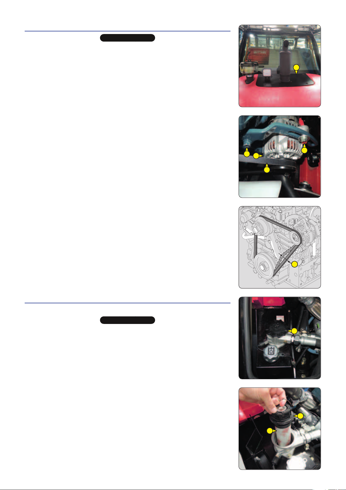
REPLACE Alternator belt
IMPORTANT
Check the belt tension again after the first 20 hours of operation.
- Remove the access panel 1.
- Loosen screws2 by two to three thread turns.
- Swivel the alternator assembly so as to free the belt 3.
NOTE: Take the opportunity provided by the removal of the belt to check that the
pulleys and bearings are working correctly (noise, friction, play, etc.).
- Remove the belt and replace with a new one (
- Ensure that it is properly seated in the grooves of each pulley.
- Adjust the belt tension between the crankshaft and alternator pulleys.
- Swivel the alternator assembly so as to obtain the required belt tension.
- Under normal pressure applied by the thumb (98 N), belt movement A should be
between 10 and 12mm.
- Retighten the screws 2.
FILTER CARTRIDGES AND BELTS).
1
REPLACE Hydraulic return oil filter cartridge
Place the lift truck on level ground with the engine stopped.
IMPORTANT
Do not operate the lift truck without the cartridge in place, as this would immediately damage the hydraulic
transmission system, the pump and the hydrostatic wheel motors.
- Release the pressure from the circuits by operating the hydraulic controls.
- Open the engine cover (2-DESCRIPTION-INSTRUMENTS AND CONTROLS).
- Carefully clean the outside of the filter and the area surrounding it
- Unscrew the plug 1 with a wrench.
- Remove the hydraulic oil filter cartridge 2 from the filter head 3 and replace it with
a new one (FILTER CARTRIDGES AND BELTS).
- Refit the unit.
2
2
3
2
A
1
3 - 23
3
2
647837 M1 (A052020)
MC 18-2/18-4 D K ST5 S1
Page 96

REPLACE Cab fan filters (OPTION)
INTERIOR CAB VENTILATION FILTER
- Remove the protective grid1.
- Remove the cab ventilation filter(2) and replace it with a new one ( FILTER
CARTRIDGES AND BELTS).
- Refit the protective grid.
EXTERIOR CAB VENTILATION FILTER
- Remove the floor mat.
- Remove the cab ventilation filter3 and replace it with a new one (
CARTRIDGES AND BELTS).
- Put back the floor mat.
FILTER
2
1
3
CHECK Hoses and differential pressure hoses for the exhaust particle filter "DPF" **
CHECK Exhaust gas recirculation piping "EGR" **
CHECK Intake hose **
CHECK
Exhaust manifold **
CHECK Fork wear *
** Engine service, consult your dealer.
* Consult your dealer.
3 - 24
647837 M1 (A052020)
MC 18-2/18-4 D K ST5 S1
Page 97

3 - 25
647837 M1 (A052020)
MC 18-2/18-4 D K ST5 S1
Page 98

1000H-PERIODIC SERVICE-EVERY 1,000 HOURS OF SERVICE OR 2 YEARS
Âo
ALSO CARRY OUT THE PERIODIC MAINTENANCE FOR 500 HOURS OF SERVICE.
CHECK Seat belt
IMPORTANT
It is forbidden to use the lift truck if the seat belt is defective (fixing, locking, cuts, tears, etc.).
Immediately repair or replace the seat belt.
SEAT BELT WITH TWO ANCHORING POINTS
- Check the following points:
• Fixing of the anchoring points on the seat.
• Cleanness of the strap and the locking mechanism.
• Triggering of the locking mechanism.
• Condition of the strap (cuts, curled edges).
REELED SEAT BELT WITH TWO ANCHORING POINTS
- Check the points listed above together with the following points:
• The correct winding of the belt.
• Condition of the reel guards.
• Roller locking mechanism when the strap is given a sharp tug.
NOTE: Following an accident, the seat belt must be replaced.
CLEAN Fuel tank
Place the lift truck on level ground with the engine stopped.
IMPORTANT
While carrying out these operations, do not smoke or work near a flame.
Never try to carry out a weld or any other operation by yourself, this could provoke an explosion or a fire.
- Inspect the parts of the fuel circuit and the tank liable to leak, both visually and
by touch.
- In the event of a leak, contact your dealer.
- Place a container under the drain plug 1 and unscrew it.
- Remove the filler plug2 to ensure correct drainage.
- Rinse with ten litres of clean diesel through the filler hole(3).
- Refit and tighten the drain plug1 (tightening torque 73-97 N.m).
- Fill the fuel tank with clean, filtered diesel.
- Turn on the lift truck's ignition to bleed air from the circuit.
NOTE: If necessary, activate the pump by hand 4 to facilitate starting of the engine.
1
3
2
4
3 - 26
647837 M1 (A052020)
MC 18-2/18-4 D K ST5 S1
Page 99

REPLACE Engine crankcase ventilation filter
- Open the engine cover (2-DESCRIPTION-INSTRUMENTS AND CONTROLS).
- Remove the air filter 1 and its holder.
- Carefully clean the outside of the filter 2 and its holder to prevent dust from getting
into the system.
- Disconnect the hose3 at the filter.
- Unscrew the cover4.
- Take out the filter 5 and discard it together with the seal of the cover 3.
- Check the condition of the recycling valve (cracks, breaks or abnormal deposits)
inside the head of the filter 6.
- Refit a new seal on the cover and insert a new filter (
BELTS).
- Tighten the cover 4 by hand only and lock in place by a quarter turn.
- Reconnect the hose 3.
- Refit the air filter.
FILTER CARTRIDGES AND
1
2
4
6
5
4
REPLACE Dry air filter cartridge
For very dusty atmospheres, there are pre-filtration elements ( FILTER CARTRIDGES
AND BELTS).
In very dusty atmospheres, with pre-filtration, the cartridge replacement interval must
be reduced to 250 hours.
IMPORTANT
Replace the cartridge in a clean location.
Never operate the lift truck with the air filter removed or damaged.
- Switch off the engine.
- Open the engine cover (2-DESCRIPTION-INSTRUMENTS AND CONTROLS).
- Loosen the locks and remove cover1.
- Gently remove the cartridge2 to reduce dust falling as far as possible.
- Leave the safety cartridge in place.
- Carefully clean the following parts with a damp, clean lint-free cloth.
• The inside of the filter and cover.
• The inside of the filter inlet hose.
• The gasket surfaces in the filter and in the cover.
- Check pipes and connections between the air filter and the engine.
- Check the connection and condition of the clogging indicator on the filter.
- Before fitting check the condition of the new cartridge (FILTER CARTRIDGES
AND BELTS).
- Introduce the cartridge into the filter axis, pressing on the edges and not the middle.
- Reassemble the cover, guiding the valve downwards.
3
1
2
3 - 27
647837 M1 (A052020)
MC 18-2/18-4 D K ST5 S1
Page 100

REPLACE Coolant
These operations are to be carried out as necessary or every two years at the beginning
of winter.
IMPORTANT
The engine does not contain any anti-corrosion element and must be filled with a mixture containing25% of ethylene
glycol-based antifreeze all year round.
- Place the lift truck on level ground with the engine stopped and cold.
- Open the engine cover (2-DESCRIPTION-INSTRUMENTS AND CONTROLS).
- Remove the access panel 1.
DRAINING THE LIQUID
- Place a container under the hose2 of the radiator and under the hose3 of the
exhaust gas recycling valve cooler.
- Undo the clamps 4 and remove the hose 2 and the hose 3.
- Remove the filler plug5 to ensure correct drainage.
- Let the cooling circuit drain entirely while ensuring that the ports do not get clogged.
- Check the condition of the hoses and their attachments, and change if necessary.
- Rinse the circuit with clean water, or use a cleaning agent if necessary.
FILLING WITH COOLANT
- Refit the hose 2 and the hose 3.
- Slowly fill the system with the coolant (
through the filler hole5.
- Refit the filler plug.
- Run the engine at idle for a few minutes.
- Visually check that there is no leakage in the radiator and pipes.
- Check the level and refill if necessary.
- The liquid must be at the MAXIMUM level on the expansion tank 6.
MAINTENANCE: LUBRICANTS AND FUEL)
1
5
6
2
4
3 4
3 - 28
647837 M1 (A052020)
MC 18-2/18-4 D K ST5 S1
 Loading...